

Lainox Naboo Compact CVEN061, Naboo Compact CVES061, Naboo Compact CBEN061, Naboo Compact CBES061, Naboo Compact COEN061 Owner's Manual
...Page 1

Compact by Naboo
Compact by Sapiens
Heart
Gas-Fired or Electric
Combi Oven/Steamer
OWNER'S
MANUAL
90028771rev00
Page 2

2
90028771rev00
Page 3
FOR YOUR SAFETY
Do not store or use
gasoline or other
flammable vapors or
liquids in the vicinity of
this or any other appliance.
FOR SAFE AND EFFICIENT OPERATION OF THIS EQUIPMENT, THIS MANUAL MUST BE
RETAINED BY THE OWNER/USER FOR FUTURE REFERENCE.
GAS LEAK INSTRUCTIONS
Post in a prominent
location, instructions to
be followed in the event of
user smelling gas.
This information shall be
obtained by consulting the
local gas supplier.
WARNING
Improper installation,
adjustment, alteration
service or maintenance
can cause property
damage, injury or death.
Read the installation,
operating and maintenance
instructions thoroughly
before installing or
servicing this equipment.
WARNINGS
WARNING
DEATH, INJURY, AND EQUlPMENT DAMAGE could result from improper installation
of the Oven/Steamer, or from installation of a unit damaged during shipment or
storage. Either of these conditions could also void the equipment warranty. DO
NOT INSTALL a Oven/Steamer suspected of damage.
Install the Oven/Steamer according to the policies and procedures outlined in this
manual.
WARNING
NEVER EXCEED 14”/355.6 mm WATER COLUMN (1/2 psi) GAS PRESSURE.
If the gas supply pressure exceeds 14”/355.6 mm water column, a pressure
regulating valve must be installed in the gas supply plumbing to reduce the gas
pressure to less than 14”/355.6 mm water column.
WARNING
Using water not within the limits specified in this manual could void or adversely
affect the warranty coverage of the Oven/Steamer.
WARNING
The flooring directly under this unit must be made of non-combustible material.
WARNING
CAUTION - To reduce the risk of the fire, the appliance is to be installed in non-
combustibile surroundings only, with no combustibile material within 18 inches of
the sides, front, or rear of the appliance or within 40 inches above the appliance.
The appliance is to be mounted on floors of noncombustibile construction with
noncombustibile flooring and surface finish and with no combustibile material
against the underside, or on no combustibile material against the undrside. Such
construction shall in all cases extend not less than 12 inches beyond the equipment
on all sides.
3
90028771rev00
Page 4
WARNINGS
WARNING
All clearance requirements above, below, and around the unit are the same
for combustible or non-combustible locations.
Maintain at least 20”/500 mm clearance on the right of the unit.
Maintain at least 10”/254 mm clearance at the rear of the unit.
Maintain at least 40”/1000 mm clearance above the unit.
WARNING
Malfunctions and equipment damage may result from improper mounting.
Malfunctions and/or damage resulting from improper mounting are not covered
by the equipment warranty. The Oven/Steamer MUST BE LEVEL BOTH FRONT TO
BACK AND SIDE TO SIDE in all mounting arrangements.
Equipment damage may result from shifting the Oven/Steamer more than 3° out of
level while power is turned on.
WARNING
INJURY AND EQUIPMENT DAMAGE could result from improper lifting. Refer to the
appropriate dimension and check the weight of the unit being installed.
Use enough workers with experience of lifting heavy equipment to place the
Oven/Steamer on the supporting surface.
WARNING
DEATH, INJURY, AND EQUIPMENT DAMAGE could result from improper installation
of the drain outlet lines.
Improper installation of these lines could void the Oven/Steamer warranty.
The following restrictions are critical to the safety of personnel and equipment, and
must not be violated under any circumstances.
Do not connect the drain line into PVC pipe, or any other drain material
that cannot sustain 180 °F/82 °C.
Do not connect drains from any other equipment to the Oven/Steamer drain line.
Do not connect the drain outlet extension line directly to a floor drain or sewer line.
Do not block drain vents at the top of the unit (
).
4
90028771rev00
Page 5
WARNINGS
WARNING
DO NOT TRY TO LIGHT THE BURNERS OR PILOT WITH A FLAME.
THERE IS NO PILOT TO LIGHT OR ADJUST.
Ovens/Steamers have electronic ignition systems which automatically light the
burners, sense the flame, and control gas flow. This provides both precise burner
control and safety ignition and shutdown features.
DEATH, INJURY OR EQUIPMENT DAMAGE may result from an improperly adjusted
gas control and ignition system. Do not alter any adjustments on this electronic
control or solenoid valve. If adjustment is required, contact an authorized service
center. The Manufacturer is in no way responsible for the operation or safety of this
equipment if the controller, valve, or igniter probe are adjusted by anyone other
than a authorized service representative.
WARNING
Equipment damage and faulty operation will result if the gas, water, or electrical
supplies fall below requirements. This may be caused by other equipment on the
same supply lines. During all tests, adjustments, and inspection of the Oven/
Steamer, turn on all equipment drawing on the same supply lines.
WARNING
DO NOT ATTEMPT TO START OR OPERATE a Oven/Steamer during
a power outage. Critical safety circuits are not energized, and serious injury to
personnel or damage to equipment may result.
DEATH, INJURY, AND EQUIPMENT DAMAGE could result from improper operation
of the Oven/Steamer.
Be sure oven/steamer has been installed correctly according to the installation
instructions in Chapter 2 before starting operation.
5
90028771rev00
Page 6
WARNINGS
WARNING
For these appliances, the state of the metal components in direct contact with the
source of heat must be checked. It is therefore advisable to make an annual visual
check on the combustion chamber.
This precaution is sufficient to prevent any irreparable damage to the appliance.
WARNING
Steam leaks around the door, cooking compartment flooding, reduced cooking
performance, and compartment implosion can be caused by a blocked drain or
drain screen. Inspect and clean the drain and drain screen before each use.
Never operate the steamer without the screen in place.
WARNING
Do not use flammable cleaning agents to clean the Oven/Steamer, or in the vicinity
of this appliance.
WARNING
Avoid any operation which leads to cooking salt being deposited on the steel
surfaces of the oven. Should this happen, clean thoroughly and immediately.
WARNING
Before using your new appliance clean out the oven carefully. Do not use acids
or corrosive cleaners, wire wool or brushes to clean either the oven cavity or the
appliance cabinet (use warm water with a suitable detergent).
WARNING
Inside of oven/steamer stays hot for a long time. Be careful when cleaning inside
oven/steamer compartment.
WARNING
Oven cleaners are caustic and if wrongly used can irritate the skin and eyes.
Always follow the Manufacturer’s instructions to the letter.
6
90028771rev00
Page 7
WARNINGS
WARNING
Let rinse water drain through compartment drain opening. If water does not drain
freely, drain lines must be cleaned before cooking again. Clogged or slow drains
are dangerous because hot water can collect in compartment and spill out when
opening compartment door.
WARNING
DEATH, INJURY, OR EQUIPMENT DAMAGE may result from improper service or
maintenance practices. Always turn the main power switch to OFF for any unit before
starting service, maintenance or repairs.
WARNING
Steam leaks around the door, cooking compartment flooding, reduce cooking
performance, and compartment implosion can be caused by a blocked compartment
vent, or a blocked drain or drain screen. Inspect and clean the compartment vent,
drain and drain screen before each use.
Never operate the oven/steamer without the screen in place.
WARNING
The liquid phosphoric acid in descaling can be harmful if not handled properly.
Follow these basic safety rules for handling and using acid.
Wear protective clothing when mixing or applying chemical cleaners. Wear rubber
gloves, mask and approved cup-type goggles.
Avoid breathing fumes. If liquid comes in contact with skin, flush immediately with
large quantities of cold water. Remove contaminated clothing.
If chemical contacts eyes, flush with cold water for a minimum of 15 minutes.
Get immediate medical attention.
If chemical is swallowed or ingested, follow instructions on the chemical container.
Get immediate medical attention.
WARNING
DEATH, INJURY, OR ELECTRIC SHOCK can occur by touching electrical
components and wires inside the access panel when the main power switch is in
the ON position. NEVER REMOVE THE SERVICE ACCESS PANEL.
Allow only Authorized Service Representatives to perform service, maintenance,
and repairs that require the removal of the service access panel(s).
7
90028771rev00
Page 8
WARNINGS
WARNING
DEATH, INJURY, OR ELECTRIC SHOCK can occur by touching electrical,
components and wires inside the access panel when the main power switch is in
the ON position. NEVER REMOVE THE SERVICE ACCESS PANEL.
Allow only Authorized Service Representatives to perform service, maintenance,
and repairs that require the removal of the service access.
WARNING
This appliance has more than one power supply connection point. Disconnect the
power supply before replacing fuses.
ONLY FOR DOUBLE STACK VERSION
WARNING
WHEN APPLIANCE IS PROVIDED WITH CASTERS
-RISK OF ELECTRIC SHOCK-
APPLIANCE MUST BE SECURED TO BUILDING STRUCTURE.
SEE INSTALLATION INSTRUCTION
NOTICE
When this appliance is installed with casters, it must be installed with the casters
supplied, a connector complying with either ansi z21.69-csa 6.16 and a quick-
disconnect device complying with ansi z21.41-csa 6.9.
it must also be installed with restraining means to guard against transmission of
strain to the connector, as specified in the appliance manufacturer’s instruction.
The casters with brake must be on the front of the appliance
8
90028771rev00
Page 9

PROTECTING WARRANTY COVERAGE
The warranty printed to the left specifies the owner/user’s responsibility for proper
installation, operation and maintenance of the Combi Unit.
If these responsibilities are not met, the Limited Warranty and/or Extended Limited
Warranty coverage may be adversely affected.
The following table is provided to assist the owner/user in meeting these responsibilities. In
addition, the warranty advantages of installing a Steamer Gard water treatment system are
explained after the table.
The Warranty Protection Table lists installation, operation, and maintenance factors that
have in the past adversely affected warranty coverage.
The owner/user of a Combi Unit should pay particular attention to these factors to protect
his warranty coverage.
This table is not a comprehensive list of the owner/user’s responsibilities.
The Steamer are intended for use only by professionally trained personnel.
To meet his responsibilities, the owner/user must supplement this guide with any additional
actions consistent with the operation of steam generating food preparation equipment by a
trained professional.
9
90028771rev00
Page 10
TABLE OF CONTENTS
Chapter Page
CHAPTER 1. PRODUCT IDENTIFICATION 12
MODEL NUMBER 12
PRODUCT TAGS 12
IDENTIFICATION PLATE 12
OVEN MODELS AND VERSION 13
TECHNICAL DATA 14
CHAPTER 2. INSTALLATION INSTRUCTIONS 15
INTRODUCTION 15
INSTALLATION POLICIES 15
INSTALLATION OVERVIEW 16
INSTALLATION DIAGRAM NOTES 19
INSTALLATION DIAGRAMS 20
PREPARATION FOR INSTALLATION 33
Unpacking and Inspection 33
Shipping Damage Instructions 33
Protecting The Oven / Steamer 33
Electric Power Requirements 34
Gas Supply Requirements 34
Water Quality Requirements 34
Softened, Treated, or Filtered Water 35
Water Supply System 36
Selecting The Operating Location 36
INSTALLATION INSTRUCTIONS 38
Position and Level the Oven/Steamer 38
Leg Mounting and Leveling 39
Assembly 39
Positioning and Leveling 40
Appliance equipped with casters 41
Install and Connect the Free Air Vented Drain Lines 42
Exhaust Port Ventilation 45
Install Electric Power Line 46
Connect Electrical Line 47
Install and Connect Water Supply Lines 48
Testing Water Supply Lines 50
Install and Connet Gas Supply Lines 50
Testing Gas Supply Lines and Burner Controls 51
Pressure Testing The Gas Supply Lines 51
Testing the Automatic Gas Valve and Burner Control System 52
Start-Up Check List 54
Initial Operation and Cleaning 56
Lighting Instructions 57
Shutdown Instructions 57
10
90028771rev00
Page 11
TABLE OF CONTENTS
CHAPTER 3. PREVENTIVE MAINTENANCE AND TROUBLESHOOTING 58
INTRODUCTION 58
MAINTENANCE RECORDS 58
DAILY MAINTENANCE 59
Blowdown Steam Generator 59
Cleaning 59
Inspect the Cooking Compartment Vent 59
WEEKLY MAINTENANCE 59
Clean Drain 59
Descale Steam Generator 60
Health Hazard Data, effects of Overexposure 60
Emergences and First aid Procedures 60
Troubleshooting notes 63
11
90028771rev00
Page 12
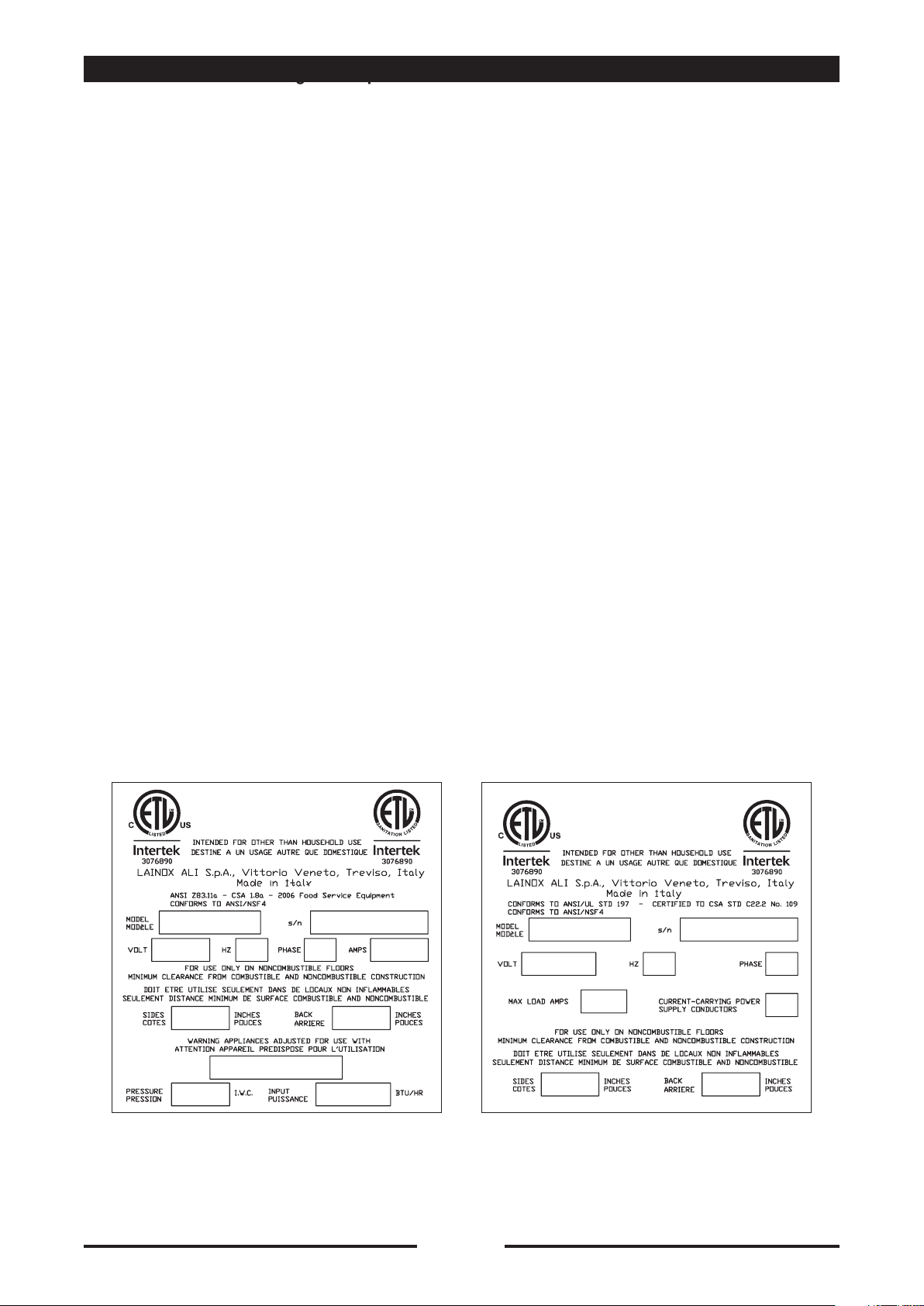
The Manufacturer assigns two product identification numbers to each Oven/Steamer:
a model number and a serial number. The model number identifies the product
characteristics. The serial number identifies the individual unit (Figure 1-1).
MODEL NUMBER
This manual covers all models (for capacit in units): each model electric or gas-fired with
or without steam generators.
Each character of a model number identifies a characteristic of the oven/steamer.
The model number begins with CBE.. (with steam generator, “E” means electric) or
CVG.. / CVE.. or COE.. (without steam generator, “E” or “G” means electric or gas-fired),
followed by a number for capacity in units. This manual covers all standard features and
options available on the Oven/Steamer models listed above.
Other than selection of options, there are presently no significant design, parts, or
operating differences among oven/steamers with the same model number.
Figures 1-2 illustrate the models and identify the major components.
CHAPTER 1. PRODUCT IDENTIFICATION
PRODUCT TAGS
Before shipping, each single unit is furnished with different tags which give you
information on appliance operation. These tags are located on the lower right side of the
unit close to the identification plate.
IDENTIFICATION PLATE
Figure 1-1 illustrates typical Identification Plates.
The plate is located on the right side of each unit as illustrated in Figures 2-1.
The Identification Plate lists the model number, gas supply requirement, power
requirements, and wiring requirements of each Oven/Steamer.
Figure 1-1. Identification Plate
12
90028771rev00
Page 13
OVEN MODELS AND VERSIONS
MODELS
CVGN 061
gas rating power BTU 29.000 (8,5 kW)
CVGS 061
MODELS
CVEN061 /CBEN061
CVEN061 /CBEN061
COEN026
COES026
COEN061
COES061
COEN101
COES101
rating power kW 8,25
rating power kW 5,25
rating power kW 7,75
rating power kW 15,5
COMPARTMENT CAPACITY
6 trays 12”x20”x21/2” max. recommended load 53 lbs. of food
COMPARTMENT CAPACITY
6 trays 12”x20”x21/2” max. recommended load 53 lbs. of food
6 trays 12”x14”x21/2” max. recommended load 36 lbs. of food
6 trays 12”x20”x21/2” max. recommended load 53 lbs. of food
10 trays 12”x20”x21/2” max. recommended load 88 lbs. of food
13
90028771rev00
Page 14
TECHNICAL DATA
Model
CVGN061 / CVGS061 BTU 29.000 - kW 8 4
Model
CVEN061 / CVES061
CBEN061 / CBES061
COEN026 / COES026 5,25
COEN061 / COES061 7,75
COEN101 / COES101 15,5
Nominal Rating
BTU/kW
Power Rating
kW
8,25
Consumption
Amps
Voltage
AC 208V
3 AC 208V
3 AC 480V
AC 208V
3 AC 208V
3 AC 480V
AC 208V
3 AC 208V
3 AC 480V
3 AC 208V
3 AC 480V
Water Pressure
kPa/Psi
200 500 kPa
35 60 Psi
Max load
V
Amps
40
30
13
25
16
7
37
23
10
46
20
Consumption
softened water
max. Liter/hr
8
Consumption
softened water
max. Liter/hr
8
8
8
8
8
8
8
8
8
8
8
Connecting wires type: use copper wires only.
*
14
14
90028771rev00
90028771rev00
Page 15
CHAPTER 2. INSTALLATION INSTRUCTIONS
This manual and several components are packaged inside the during shipment. To
access these packages, the shipping crate has been disassembled.
Discard the shipping crate and protect the from dirt and damage during storage, site
preparation, and installation as described in “Protecting The Oven/Steamer.
WARNING
DEATH, INJURY, AND EQUlPMENT DAMAGE could result from improper installation
of the Oven/Steamer, or from installation of a unit damaged during shipment or
storage. Either of these conditions could also void the equipment warranty.
DO NOT INSTALL a Oven/Steamer suspected of damage.
Install the Oven/Steamer according to the policies and procedures outlined in this
manual.
INTRODUCTION
This chapter is a guide for installation of the Oven/Steamer models identified in Chapter
1. This guide is for use by qualified professionals, and does not include all procedures
and precautions in the common domain of licensed plumbers, pipe fitters, and
electricians, or experienced food service equipment installers.
This guide must be used in conjunction with professional experience and a thorough
understanding of the local and national utility, construction and sanitation codes; the
most prominent of which are listed in the Installation Policies section below.
Before starting installation, the owner and the installer should read through this chapter
and thoroughly understand and agree upon:
• The installation policies of The Manufacturer as stated in Installation Policies.
• An installation plan based on the Installation Overview and Installation Check List.
• Responsibility for feed water quality and its testing as described in Preparation For
Installation, Water Quality Requirements.
INSTALLATlON POLICIES
• The Oven/Steamer must be installed by qualified plumbing and electrical personnel,
working to all applicable national and local codes. Equipment installation must comply
with the Basic Plumbing Code of the Building Officials and Code Administrators
International, Inc. (BOCA), the National Fuel Gas Code, ANSI Z223.1-(latest edition) or
the Natural Gas Installation Code CAN/CGA-B149.1 or the propane Installation Code
CAN/CGA-B149.2, the National Electric Code, ANSI/NFPA No. 70-(latest edition) or the
Canadian electrical code, CSA 22.1, and the Food Service Sanitation Manual of the Food
and Drug Administration (FDA).
15
90028771rev00
Page 16

CHAPTER 2. INSTALLATION INSTRUCTIONS
• All models of the Oven/steamers comply with the applicable standards for
manufacturers. Included among those certification agencies are: etl and NSF.
• The Oven/Steamers are certified for safe operation only when permanently installed in
accordance with local and/or national codes.
Many local codes exist, and it is the responsibility of the owner and installer to comply
with these codes.
• In no event shall the Manufacturer assume any liability for damage or injury
resulting from installations which are not in strict compliance with the Installation
Instructions and the codes cited above. Specifically, The Manufacturer will not
assume any liability for damage or injury resulting from improper installation of
equipment, including, but not limited to, temporary or mobile installations.
INSTALLATION OVERVIEW
Installation of the Oven/Steamer is presented in two parts: preparation and installation.
The Installation Check List, Table 2-1, lists the major tasks to be performed in a
recommended sequence. Each item references the instructions for starting the task.
Complete the preparation tasks in sequence, and then the installation tasks.
Installation requirements may vary from site to site; adapt the check list accordingly.
Schematic Installation Diagram, Figure 2.1, illustrates the utility lines and connections
required to install the Oven/Steamer.
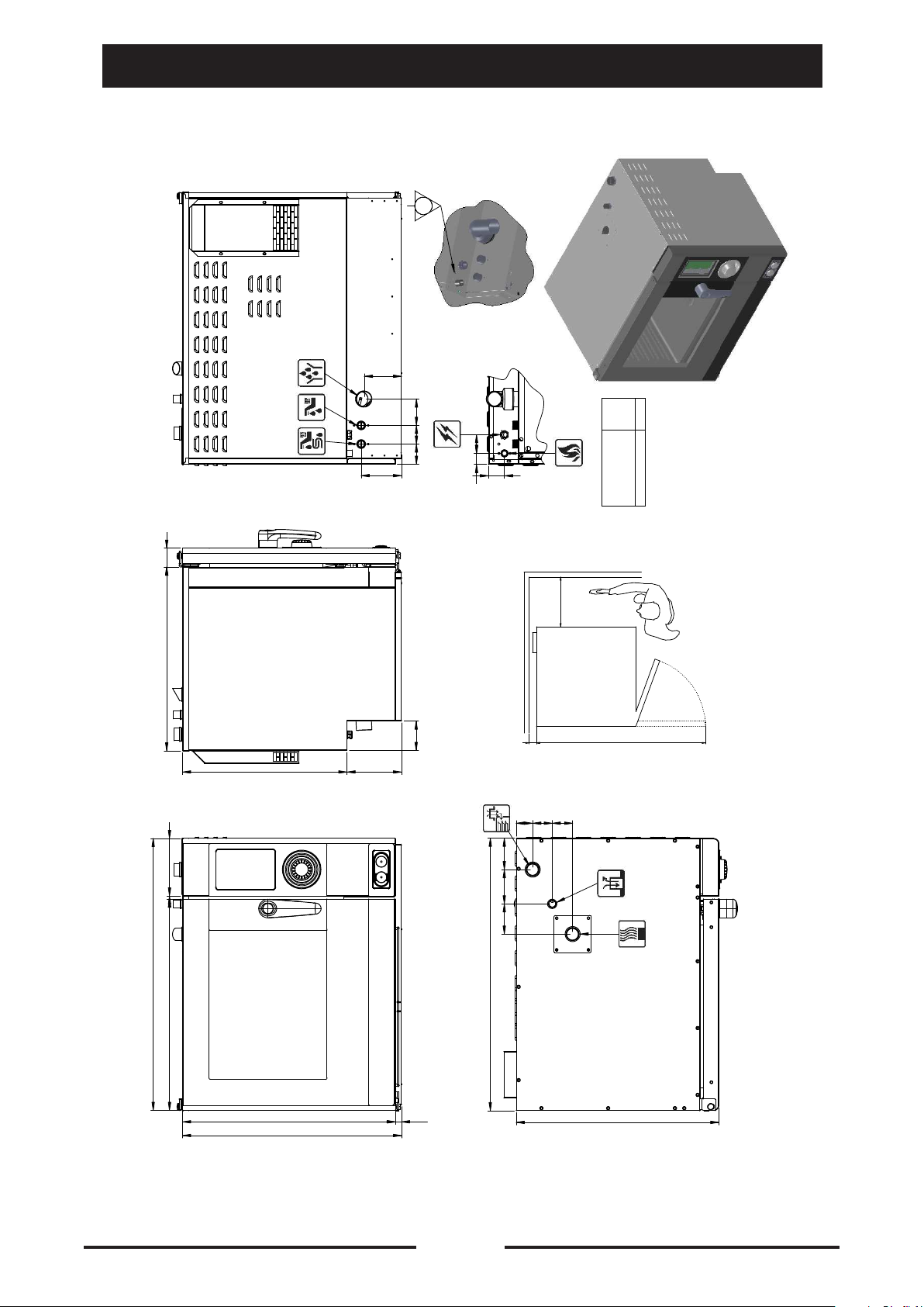
The Dimension Drawings, Fig. 2-2, show the required utility connection points,
dimensions, and clearances for each model.
16
90028771rev00
Page 17

TABLE 2-1. INSTALLATION CHECK LIST
TASK PAGE
REFERENCE
PREPARATION
Unpack, inspect, and protect the unit. 33
Check electric power requirements. 34
Check gas power requirements. 34
Test supply water quality. 34
Select water treatment system. 36
Select operating location. 36
INSTALLATION
Position and level steamer. 38
Assemble packaged components. 38
Install and connect drain line. 43
Connect exhaust flue diverter. 44
Install and connect electrical line. 47
Install and connect water supply lines. 49
Test water supply lines. 50
Install and connect gas supply lines 50
Test gas supply lines. 51
Perform start-up checks. 55
17
90028771rev00
Page 18
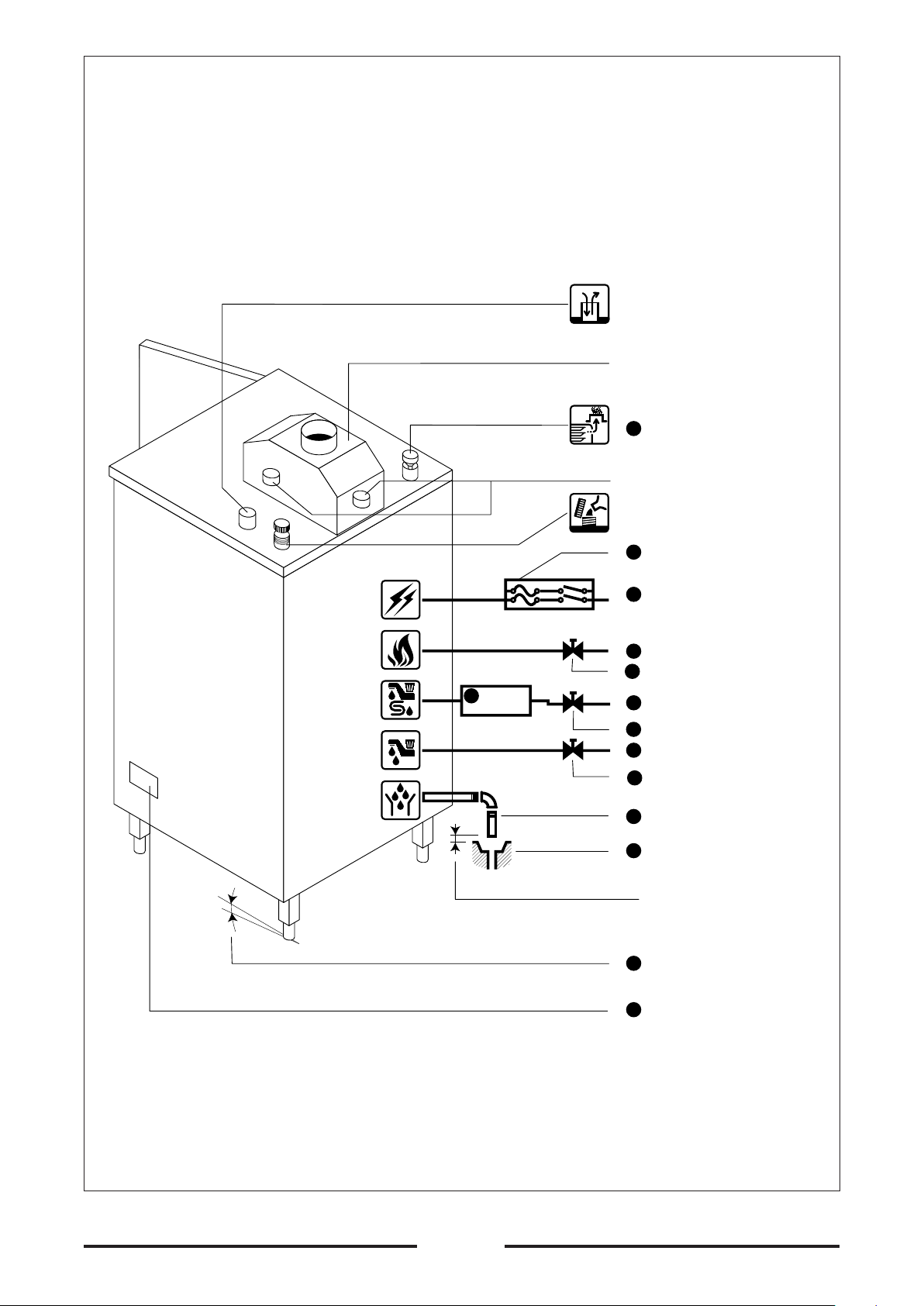
CONNECTION
ELECTRICAL
SUPPLY
SAFETY VENT HOLE
(DO NOT BLOCK)
FLUE DIVERTER
10
DRAIN EXHAUST VENT
(DO NOT BLOCK)
CONNECTIONS: EXHAUST FROM
OVEN AND STEAM GENERATOR
INLET FOR DESCALING SOLUTION
(OPEN FOR DESCALING ONLY)
MAIN POWER SWITCH AND
2
FUSE BOX
1
MAIN ELECTRIC POWER
SUPPLY
3∞
CONNECTION
GAS SUPPLY
CONNECTION
Steam Generator and
Humidifier Supply
CONNECTION
Steam Condenser and
Steam Generator rinsing
Supply
CONNECTION
Free Air Vented Drain
6
STEAMER
GUARD
11
MAIN GAS SUPPLY
12
MAIN MANUAL GAS SHUT-OFF
VALVE
4
HOT (MAX 122 ∞F/50 ∞C) COLD
SOFTENED WATER SUPPLY
7
WATER SUPPLY SHUT-OFF VALVE
UNTREATED NORMAL COLD
5
WATER SUPPLY
7
WATER SUPPLY SHUT-OFF VALVE
DRAIN LINE
8
9
FLOOR DRAIN
25 mm / 1 INCH
CLEARANCE MINIMUM
(only for version "D")
LEVELING
3
IDENTIFICATION PLATE
1
18
90028771rev00
Figure 2-1
Page 19
INSTALLATION DIAGRAM NOTES
1-
The Product Identification Plate located on the right side service panel specifies the
electric power requirements.
2-
For each unit, the installer must provide a ground connection and a separate fused
disconnect switch.
3-
Catastrophic damage will result from shifting the more than 3° out of level while power is
turned on at the unit’s main power switch.
4-
The unit must have an untreated cold water supply NOT HOT, and a HOT (max.
122 °F/50 °C) cold softened water supply.
5-
The softened water supply must meet the quality requirements of Table 2-2, and the
pressure requirements on installation diagrams (Fig. 2-2).
6-
A Steamer Gard system is recommended when water quality does not meet the Table 2-2
requirements.
7-
A manual water shut-off valve must be installed between the main softened water supply
and the steamer supply line. Refer to Figures 2-8 and 2-9 for recommended component
arrangements. A manual water shut-off valve must be installed between the main
untreated main water supply and the steam condenser supply line.
8-
The drain line: use a heat-resistant plastic pipe (not flexible), installed without loops
or kinks and no longer than 2 meters with a slope of no less than 4 degrees, or realize
a drain line with a gravity flow away from the Oven. Drain line must not be connected
to the drain lines of any other equipment. In compliance with current standards, the
drainage piping must not be connected in a straight line.
9-
It is advisable to interpose a funnel (see drawing) to facilitate flow. DO NOT REDUCE
THE DRAIN LINE DIAMETER. DO NOT INSTALL A TRAP ON THE DRAIN LINE.
10-10-
Never block the drain exhaust vent and at the top of the Oven.
WARNING
NEVER EXCEED 14”/355.6 mm WATER COLUMN (1/2 psi) GAS PRESSURE.
If the gas supply pressure exceeds 14”/355.6 mm water column, a pressure
regulating valve must be installed in the gas supply plumbing to reduce the gas
pressure to less than 14”/355.6 mm water column.
11-11-
A main manual gas shut-off valve must be installed between the main gas supply and the
Oven/Steamer gas supply line.
12-
Refer to figures 2-1 for the recommended component arrangements.
19
90028771rev00
Page 20

INSTALLATION
DIAGRAMS
20
90028771rev00
Page 21
Los datos tecnicos indicados en el presente catalogo no son vinculantes. La empr esa se reserva el derecho de efectuar modificationes sin previo aviso.
I dati riportati sul presente documento sono da ritenersi non vincolanti. L'azienda si riserv a di apportare modifiche tecniche in qualsiasi momento.
The specification shown in this document are to be considered non binding. The company res erves the right to make technical change at any moment.
Die auf dieser Unterlage angegebenen technishen Daten sind als unverbinlich anzusehen. Die Firma behält sich das Rec ht vor zu jeder zeit technische Änderungen vorzunehmen.
Les données techniques sur ce document ne doivent pas être cons idérées contraigrantes. La societé se réserve le droit d'apporter des modification techniques à tout moment.
CVGN/S061 (inch)
CVGN061 / CVGS061 / inch
2,36
23
ø2"ø3/4
ø3/4
5
AC 120V
2,56 2,36 3
5,12
4
1,42 2,36
2
0,3 51,2
ø1/2
19,7
7 21
2 2
ø1-1/2"
3
ISO 228.1
R 1/2"
EN10226
DK
EE-LV-LT-MT-SK-SI-HR
IT-LU-NO-NL-PT-GB-SE
DE-AT-BE-ES-FI-FR-GR-IE
CH-HU-CZ-BG-CY-PL-TR
34,45
7,28
26,77 0,39
26,97 0,79
27,76
ø1"
4 3,98 4
ø1,5"
34,45
26
21
90028771rev00
Page 22

Los datos tecnicos indicados en el presente catalogo no son vinculantes. La empr esa se reserva el derecho de efectuar modificationes sin previo aviso.
I dati riportati sul presente documento sono da ritenersi non vincolanti. L'azienda si riserv a di apportare modifiche tecniche in qualsiasi momento.
The specification shown in this document are to be considered non binding. The company res erves the right to make technical change at any moment.
Die auf dieser Unterlage angegebenen technishen Daten sind als unverbinlich anzusehen. Die Firma behält sich das Rec ht vor zu jeder zeit technische Änderungen vorzunehmen.
Les données techniques sur ce document ne doivent pas être cons idérées contraigrantes. La societé se réserve le droit d'apporter des modification techniques à tout moment.
CVGN/S061 (US)
CVGN061 / CVGS061 / mm
120
60
590
185 680
10
ø3/4 ø50
ø3/4
AC 120V
130
65 60 85
95
36 60
52
6,5 1300
ø1/2
500
175 530
ø40
65 63 53
ISO 228.1
R 1/2"
EN10226
DK
EE-LV-LT-MT-SK-SI-HR
IT-LU-NO-NL-PT-GB-SE
DE-AT-BE-ES-FI-FR-GR-IE
CH-HU-CZ-BG-CY-PL-TR
101 110 97
ø25
875
705
20 685
22
90028771rev00
ø40
875
650
Page 23

Los datos tecnicos indicados en el presente catalogo no son vinculantes. La empr esa se reserva el derecho de efectuar modificationes sin previo aviso.
I dati riportati sul presente documento sono da ritenersi non vincolanti. L'azienda si riserv a di apportare modifiche tecniche in qualsiasi momento.
The specification shown in this document are to be considered non binding. The company res erves the right to make technical change at any moment.
Die auf dieser Unterlage angegebenen technishen Daten sind als unverbinlich anzusehen. Die Firma behält sich das Rec ht vor zu jeder zeit technische Änderungen vorzunehmen.
Les données techniques sur ce document ne doivent pas être cons idérées contraigrantes. La societé se réserve le droit d'apporter des modification techniques à tout moment.
CVEN/S061 (inch)
CVEN061 / CVES061 / inch
23 2,36
ø2"ø3/4
ø3/4
21 7
5
AC 208V
3AC 208V
3
2,56 2,36
5,12
4
3AC 480V
1,42 2,36
ø1-1/2"
2,05
0,3 51,2
2 2
19,7
34,45
7,28
0,39 26,77
3,98
4
ø1"
34,45
26,97
27,76
0,79
26
23
90028771rev00
Page 24

ø3/4 ø50ø3/4
Los datos tecnicos indicados en el presente catalogo no son vinculantes. La empr esa se reserva el derecho de efectuar modificationes sin previo aviso.
I dati riportati sul presente documento sono da ritenersi non vincolanti. L'azienda si riserv a di apportare modifiche tecniche in qualsiasi momento.
The specification shown in this document are to be considered non binding. The company res erves the right to make technical change at any moment.
Die auf dieser Unterlage angegebenen technishen Daten sind als unverbinlich anzusehen. Die Firma behält sich das Rec ht vor zu jeder zeit technische Änderungen vorzunehmen.
Les données techniques sur ce document ne doivent pas être cons idérées contraigrantes. La societé se réserve le droit d'apporter des modification techniques à tout moment.
CVEN/S061 (US)
CVEN061 / CVES061 / mm
120
3AC 480V
AC 208V
3AC 208V
60
590
185 680
10
530
175
130
65 60 85
95
36 60
ø40
52
500
6,5 1300
53 63
101
110
ø25
875
705
20 685
24
90028771rev00
875
650
Page 25

Los datos tecnicos indicados en el presente catalogo no son vinculantes. La empr esa se reserva el derecho de efectuar modificationes sin previo aviso.
I dati riportati sul presente documento sono da ritenersi non vincolanti. L'azienda si riserv a di apportare modifiche tecniche in qualsiasi momento.
The specification shown in this document are to be considered non binding. The company res erves the right to make technical change at any moment.
Die auf dieser Unterlage angegebenen technishen Daten sind als unverbinlich anzusehen. Die Firma behält sich das Rec ht vor zu jeder zeit technische Änderungen vorzunehmen.
Les données techniques sur ce document ne doivent pas être cons idérées contraigrantes. La societé se réserve le droit d'apporter des modification techniques à tout moment.
CBEN/S061 (inch)
CBEN061 / CBES061 / inch
23 2,36
ø2"ø3/4
ø3/4
21 7
5
3AC 480V
AC 208V
3AC 208V
2,36
5,12
2,56 3
4
1,42 2,36
ø1-1/2"
2,04
0,3 51,2
2
2
19,7
34,45
7,28
0,39
26,77
3,98 4
ø1"
9,13
34,45
26,97
27,76
0,79
1,34
26
25
90028771rev00
Page 26

Los datos tecnicos indicados en el presente catalogo no son vinculantes. La empr esa se reserva el derecho de efectuar modificationes sin previo aviso.
I dati riportati sul presente documento sono da ritenersi non vincolanti. L'azienda si riserv a di apportare modifiche tecniche in qualsiasi momento.
The specification shown in this document are to be considered non binding. The company res erves the right to make technical change at any moment.
Die auf dieser Unterlage angegebenen technishen Daten sind als unverbinlich anzusehen. Die Firma behält sich das Rec ht vor zu jeder zeit technische Änderungen vorzunehmen.
Les données techniques sur ce document ne doivent pas être cons idérées contraigrantes. La societé se réserve le droit d'apporter des modification techniques à tout moment.
CBEN/S061 (US)
CBEN061 / CBES061 / mm
590 60
ø50ø3/4
ø3/4
530 175
120
130
85
65 60
95
AC 208V
3AC 208V
3AC 480V
36 60
ø40
51,75
500
6,5 1300
53 63
875
185 680
10
685
705
20
26
90028771rev00
875
101
110
ø25
232
34
650
Page 27

Los datos tecnicos indicados en el presente catalogo no son vinculantes. La empr esa se reserva el derecho de efectuar modificationes sin previo aviso.
I dati riportati sul presente documento sono da ritenersi non vincolanti. L'azienda si riserv a di apportare modifiche tecniche in qualsiasi momento.
The specification shown in this document are to be considered non binding. The company res erves the right to make technical change at any moment.
Die auf dieser Unterlage angegebenen technishen Daten sind als unverbinlich anzusehen. Die Firma behält sich das Rec ht vor zu jeder zeit technische Änderungen vorzunehmen.
Les données techniques sur ce document ne doivent pas être cons idérées contraigrantes. La societé se réserve le droit d'apporter des modification techniques à tout moment.
COEN/S026 (inch)
COEN026 / COES026 / inch
5
3 3,31 2,36
ø1-1/2"ø3/4 ø3/4
1,67
6
2,41
1,97 22,6
20,08
3AC 208V
3
28,54
6
2
20,08
1,6
1,2
2
ø1-1/2"ø1-1/4"
6,69
26,38
35
0,83 0,75
3,15
25
27
90028771rev00
Page 28

Los datos tecnicos indicados en el presente catalogo no son vinculantes. La empr esa se reserva el derecho de efectuar modificationes sin previo aviso.
I dati riportati sul presente documento sono da ritenersi non vincolanti. L'azienda si riserv a di apportare modifiche tecniche in qualsiasi momento.
The specification shown in this document are to be considered non binding. The company res erves the right to make technical change at any moment.
Die auf dieser Unterlage angegebenen technishen Daten sind als unverbinlich anzusehen. Die Firma behält sich das Rec ht vor zu jeder zeit technische Änderungen vorzunehmen.
Les données techniques sur ce document ne doivent pas être cons idérées contraigrantes. La societé se réserve le droit d'apporter des modification techniques à tout moment.
COEN/S026 (US)
COEN026 / COES026 / mm
121
50 575
ø3/4 ø3/4 ø40
155
725 155
60 80
84
84
42,5
61,3
3AC 208V
50
510
880
670
21 19 170
28
90028771rev00
510
40
30
50
80
ø30 ø40
625
Page 29

Los datos tecnicos indicados en el presente catalogo no son vinculantes. La empr esa se reserva el derecho de efectuar modificationes sin previo aviso.
I dati riportati sul presente documento sono da ritenersi non vincolanti. L'azienda si riserv a di apportare modifiche tecniche in qualsiasi momento.
The specification shown in this document are to be considered non binding. The company res erves the right to make technical change at any moment.
Die auf dieser Unterlage angegebenen technishen Daten sind als unverbinlich anzusehen. Die Firma behält sich das Rec ht vor zu jeder zeit technische Änderungen vorzunehmen.
Les données techniques sur ce document ne doivent pas être cons idérées contraigrantes. La societé se réserve le droit d'apporter des modification techniques à tout moment.
COEN/S061 (inch)
COEN061 / COES061 / inch
5
3
ø1-1/2"ø3/4ø3/4
1,97
29,53
3,31 2,36
6
1,67
2,41
3AC 208V
3
28,54
6
2
20,08
20,08
26,38 0,75 6,69
35
0,83
1,6
1,2
1,97
3,15
ø1-1/2"ø1-1/4"
31
29
90028771rev00
Page 30

Los datos tecnicos indicados en el presente catalogo no son vinculantes. La empr esa se reserva el derecho de efectuar modificationes sin previo aviso.
I dati riportati sul presente documento sono da ritenersi non vincolanti. L'azienda si riserv a di apportare modifiche tecniche in qualsiasi momento.
The specification shown in this document are to be considered non binding. The company res erves the right to make technical change at any moment.
Die auf dieser Unterlage angegebenen technishen Daten sind als unverbinlich anzusehen. Die Firma behält sich das Rec ht vor zu jeder zeit technische Änderungen vorzunehmen.
Les données techniques sur ce document ne doivent pas être cons idérées contraigrantes. La societé se réserve le droit d'apporter des modification techniques à tout moment.
COEN/S061 (US)
COEN061 / COES061 / mm
121
80
ø3/4 ø40ø3/4
50
750
725
155
155
84 60
84
42,5
61,3
3AC 208V
50
510
170
510
19
880
670
21
40
30
50
80
ø40ø30
800
30
90028771rev00
Page 31

Los datos tecnicos indicados en el presente catalogo no son vinculantes. La empr esa se reserva el derecho de efectuar modificationes sin previo aviso.
I dati riportati sul presente documento sono da ritenersi non vincolanti. L'azienda si riserv a di apportare modifiche tecniche in qualsiasi momento.
The specification shown in this document are to be considered non binding. The company res erves the right to make technical change at any moment.
Die auf dieser Unterlage angegebenen technishen Daten sind als unverbinlich anzusehen. Die Firma behält sich das Rec ht vor zu jeder zeit technische Änderungen vorzunehmen.
Les données techniques sur ce document ne doivent pas être cons idérées contraigrantes. La societé se réserve le droit d'apporter des modification techniques à tout moment.
COEN/S101 (inch)
COEN101 / COES101 / inch
5
3
ø3/4 ø1-1/2"ø3/4
2
29,53
3,31 2,36
6
1,67
2,41
3AC 208V
3
37,99
6
2
20,08
20,08
35,83
44
0,83 0,75 6,69
1,6
1,2
2
3,15
ø1-1/2"ø1-1/4"
31
31
90028771rev00
Page 32

Los datos tecnicos indicados en el presente catalogo no son vinculantes. La empr esa se reserva el derecho de efectuar modificationes sin previo aviso.
I dati riportati sul presente documento sono da ritenersi non vincolanti. L'azienda si riserv a di apportare modifiche tecniche in qualsiasi momento.
The specification shown in this document are to be considered non binding. The company res erves the right to make technical change at any moment.
Die auf dieser Unterlage angegebenen technishen Daten sind als unverbinlich anzusehen. Die Firma behält sich das Rec ht vor zu jeder zeit technische Änderungen vorzunehmen.
Les données techniques sur ce document ne doivent pas être cons idérées contraigrantes. La societé se réserve le droit d'apporter des modification techniques à tout moment.
COEN/S101 (US)
COEN101 / COES101 / mm
121
80
750 50
965
ø3/4 ø3/4 ø40
155
155
60
84
84
42,5
61,3
3AC 208V
50
510
1120
21 910 19 170
32
90028771rev00
510
40
30
50
80
ø30 ø40
800
Page 33

PREPARATION FOR INSTALLATION
Select and prepare the operating location before permanently positioning the unit. Protect
the unit and packaged components during site preparation. Do not select the operating
location or start installation before checking the electric power, gas, and water quality
requirements to assure proper drainage, ventilation, and safety.
UNPACKING AND INSPECTION
The is packed in a wooden shipping crate. The fat filter is packed in a separate box.
Additional components, not assembled at the factory are packaged inside the Oven/Steamer
cooking Compartment. These are:
Owner’s Manual Flue Diverter (optional)
Wire Shelves Legs (optional)
After disassembling the shipping crate, visually inspect the for damage.
Before unpacking the separate components, inspect their shipping cartons for damage.
If the cartons are not damaged, unpack them and inspect the components for damage or loss.
• If the and its separate components are delivered in good condition, close
and reseal all the component packages. Then proceed to Protecting The Oven/Steamer.
• If any shipping carton appears damaged, refer to the Shipping Damage Instructions below.
• If the or any of the components have suffered shipping damage or loss,
refer to the Shipping Damage Instructions below.
Shipping Damage Instructions
If shipping damage or loss is discovered or suspected, observe the following guidelines in
preparing a shipping damage claim.
• Write down a description of the damage or the reason for suspecting damage as soon as
it is discovered. This will help in filling out the claim forms later.
• As soon as damage is discovered or suspected, notify the carrier that delivered the
shipment.
• Arrange for a carrier representative to examine the damage.
• Fill out all appropriate claim forms and have the examining carrier sign and date each form.
PROTECTING THE OVEN / STEAMER
While running power and supply lines to the operating location, remove the and components
from the immediate work area. To maintain them in good, clean condition and prevent loss
or damage:
1-
Leave the packaged components inside the cooking compartment.
2-
Keep the fat filter and together to prevent loss.
Keep the clean by covering it with a plastic tarp or drop cloth.
3-
4-
Do not store other items on top of the machine.
33
90028771rev00
Page 34

PROTECTING THE OVEN / STEAMER
Electric Power Requirements
The characteristics of the electric power supply must match the power requirements
specified on the Oven/Steamer product identification plate.
The plate is secured to the outside of the right-side access panel as illustrated in Figure
2-2.Gas Supply Requirements
WARNING
NEVER EXCEED 14”/355.6 mm WATER COLUMN (1/2 psi) GAS PRESSURE.
If the gas supply pressure exceeds 14”/355.6 mm water column, a pressure
regulating valve must be installed in the gas supply plumbing to reduce the gas
pressure to less than 14”/355.6 mm water column.
• Natural gas pressure must be between 4.5”/101.6 mm -14”/355.6 mm water column.
• Propane gas supply pressure must be between 11”/304.8 mm - 14”/355.6 mm water column.
WATER QUALITY REQUIREMENTS
Cold or hot water (max. 122 °F/50 °C) for steam generator and humidifier.
WARNING
Using water not within the limits specified in this manual could void or adversely
affect the warranty coverage of the Oven/Steamer.
As with any steam generating equipment, poor water quality degrades Oven/Steamer
performance. If feed water is low in Total Dissolved Solids (TDS) and free of particulate
matter, the steam generator, heating element, and valves of the Oven/Steamer will give
years of trouble-free service with a minimum of maintenance.
In some areas, even potable tap water contains a variety of impurities that can cause
costly problems in steam generating equipment.
Of primary concern are mineral salts and other impurities which remain behind as lime or
scale deposits during the steam generating process. These deposits have caused many
components to fail, including heating elements, probes, and solenoid valves.
Of equal importance is the decrease in heat transfer efficiency caused by lime and scale
deposits. Decreased heat transfer increases water and power consumption. Use of the
in areas with poor water quality requires installation of a Steamer Gard water treatment
system or increased frequency of maintenance, cleaning, and descaling.
Check the quality of supply water before starting construction of the water supply lines.
If a water treatment system must be installed to achieve acceptable water quality, install
it before connecting the water supply lines to the Oven/Steamer.
34
90028771rev00
Page 35

WATER QUALITY REQUIREMENTS
Contact a local water treatment specialist for an on-the-premises water analysis.
The recommended minimum feed water quality requirements for the Oven/Steamer are
listed in Table 2-2.
Table 2-2. Minimum Supply Water Quality Requirements
Total Dissolved Solids less than 60 parts per million
Silica less than 13 parts per million
Alkalinity less than 0 parts per million
Chloride less than 30 parts per million
pH factor greater than 7.5
Softened, Treated, or Filtered Water
Do not use softened or chlorinated water in the steam generator.
If the water supply is treated or softened either by the water company or on the
premises, it may contain chlorine or various salts.
These additives are damaging to the steam generator. Salts used to soften water cause
rapid scale buildup, and increased corrosion.
The hardness of the water has to be from 1 ÷ 4 degrees Clark (1 to 6 fH/0.5 and 2.8
dH). Some water treatment plants kill bacteria in the water by adding chlorine.
When heated in the steam generator, chlorinated water rapidly dissolves generator walls
and heater elements. In extreme cases, poisonous and highly corrosive chlorine gas is
released in the steam generator. Installing a high volume water filtering system removes
most of the salts used for water softening. Contact a local water treatment specialist or
the local water company for assistance with chlorinated water.
Always connect an untreated cold water supply to the steam quenching and boiler
rinsing water supply line. DO NOT USE HOT WATER.
The oven/steamer will not function properly or within design safety limits if hot or
warm water is supplied.
35
90028771rev00
Page 36

WATER SUPPLY SYSTEM
Select a water supply system that fulfills the following elements: the two different
inlet water supplies (softened and untreated) must provide a minimum dynamic
pressure of 35 psi (2.4 kg/cm2) and a maximum static pressure of 60 psi (4.1 kg/
cm2). If the static pressure exceeds 60 psi, a pressure regulator must be installed
in the supply lines. Refer to page 33 for detailed pressure and fitting requirements,
and for the recommended plumbing layouts.
If analysis shows that the supply water is NOT within the required limits, install a
Steamer Gard water treatment system. Figure 2-6 on page 33 illustrates a treated water
supply arrangement.
If analysis shows that the supply water is NOT within the required limits, and it is not
possible to install a Steamer Gard water treatment system, plan on increasing the
frequency of maintenance, cleaning, and descaling beyond that recommended in the
maintenance schedule (Chapter 4).
SELECTING THE OPERATING LOCATION
For safe and efficient operation, observe the following criteria when selecting an
operating location for the Oven/Steamer.
WARNING
The flooring directly under this unit must be made of non-combustible material.
1-
Do not install these units in areas where combustibles are stored or may accumulate.
The surrounding area must be clear of combustibles, including the space under the unit.
2-
A proper air supply for combustion and ventilation air is critical for safe, efficient
operation of Oven/Steamers. The area around the oven/steamer must have adequate
ventilation for gas-fired-appliances.
Air openings around the unit should not be blocked; provide adequate clearance for
proper air flow to combustion chamber.
3-
The vents for combustion and ventilation air are on the right side of the unit. Do not
block these air vents. Do not install any heat producing equipment near the air vents of
the unit.
WARNING
All clearance requirements above, below, and around the unit are the same
for combustible or non-combustible locations.
Maintain at least 20”/500 mm clearance on the right side of the unit.
Maintain at least 10”/254 mm clearance at the rear of the unit.
36
90028771rev00
Page 37

4-
The dimension drawings (Figure 2-2) specify all dimensions and clearances required for
proper operation and service of each Oven/Steamer covered in this manual.
5-
The service access panel is on the right side of the unit. Select an operating location that
allows access to the right side of the unit for service.
6-
CBE models have electric steam generators
Units have from two to four exhaust ports on the top (see on the dimensions drawing).
A chimney, flue plenum, or exhaust hood should be close enough to extend an exhaust
duct to these ports.
7-
The location selected must be capable of supporting the operational weight of the unit,
including the weight of water and food.
The Oven/Steamer operating weights are listed on the dimension drawings.
8-
The floor surface under the unit must be level and continuous with the flooring in front
of the unit. The cart must roll smoothly into the for ease of operation and maintenance of
the door-to-cart compartment seal.
37
90028771rev00
Page 38

INSTALLATION INSTRUCTIONS
After selecting and preparing the Oven/Steamer operating location, the oven/steamer
can be positioned and installed. When installation is complete, perform all start-up
checks to verify proper installation and operation.
POSITION AND LEVEL THE OVEN/STEAMER
NOTE: If there is not enough clearance behind the to install the drain, electrical, and
water lines, skip this procedure and continue with Install and Connect the Free Air
Vented Drain Lines. After installing all necessary drain, electrical, and water lines,
return to these instructions and install the unit.
The is positioned and leveled twice. First level the main unit in position.
Then place the roll-in cart in the cooking chamber, and adjust the unit level to match the
roll-in cart.
WARNING
Malfunctions and equipment damage may result from improper mounting.
Malfunctions and/or damage resulting from improper mounting are not covered by
the equipment warranty. The MUST BE LEVEL BOTH FRONT TO BACK AND SIDE TO
SIDE in all mounting arrangements.
Equipment damage may result from shifting the Oven/Steamer more than 3° out of
level while power is turned on.
Adjustable Leveling Legs only if present
The supporting legs of the Oven/Steamer are 12 inch/304.8 mm long when the adjustable
feet are fully retracted. The adjustable feet can be extended approximately 2 inches/50.8
mm. This extension provides the 4 inch/101.6 mm space below the unit required by NSF
sanitary standards, and a means of leveling the oven/steamer.
ASSEMBLY
1-
Check that the feet are fully retracted into the legs. Do not overtighten. The feet should
easily screw in and out using fingers only.
WARNING
INJURY AND EQUIPMENT DAMAGE could result from improper lifting. Refer to the
appropriate dimension and check the weight of the unit being installed.
Use enough workers with experience of lifting heavy equipment to place the on the
supporting surface.
2-
Be sure electric power is turned off at the main power switch. Place the on the left
side.
38
90028771rev00
Page 39

3-
Refer to figure 2-3 and bolt the legs to the Oven/Steamer frame. All four legs must be
installed for proper mounting of the unit.
4-
Place the oven/steamer upright on its four legs.
Figure 2-3. Leg Bolts
Oven placed on counters, if placed on a plane different from the one suggested by
the producer, must be sealed (see point A, fig. X) along all it’s perimeter with silicon
approved by NSF (type GE – red, aluminum ore transparent coloured silicones, series
RTV), on the plane. The above said is not valid if oven is equipped with feet, supplied
upon specific request.
Positioning and Leveling
1-
Check that all Unpacking and Inspection tasks are complete.
Thoroughly clean the floor area that will support the unit.
2-
Using a level, determine and mark the highest corner of the floor area that will support
the leveling legs.
WARNING
INJURY AND EQUIPMENT DAMAGE could result from improper lifting. Refer to the
appropriate dimension and check the weight of the unit being installed.
Use enough workers with experience of lifting heavy equipment to place the on the
supporting surface.
3-
Roll the cart out of the cooking compartment, and move the into position and level it.
4-4-
Extend the adjusting foot of the leg in the highest corner (marked in step 3), until that
corner of the unit is four inches above the supporting surface.
5-
Using a level, adjust the other three legs until the is level both front to back and side to
side.
39
90028771rev00
Page 40

POSITION AND LEVEL THE OVEN/STEAMER
For free-standing models, the appliance needs to be levelled: small differences in level
of the supporting surface can be eliminated with the adjustable feet (by screwing or
unscrewing them). A significantly uneven or sloping stance can affect the operation of the
oven adversely.
40
90028771rev00
Page 41

APPLIANCE EQUIPPED WITH CASTERS
ELECTRIC
• Adequate means must be provided to limit the movement of the appliance without
depending on or the transmitting stress to the electrical conduit.
• The appliance shall be installed using flexible conduit.
GAS-FIRED
• The installation shall be made with a connector that complies with the Standard for
Connectors for Movable Gas Appliances, ANSI Z21.69 – CSA 6.16, and a QuickDisconnect Devices for Use With Gas Fuel, ANSI Z21.41 – CSA 6.9.
• Adequate means must be provided to limit the movement of the appliance without
depending on the connector and the quick-disconnect device or its associated piping
to limit the appliance movement.
Locations were the restraining means may be attached to the appliance
BACK SIDE
41
90028771rev00
Page 42

INSTALL AND CONNECT THE FREE AIR VENTED DRAIN LINES
The drain outlets and the drain vent at the top of the unit and must be free air
vented to equalize the pressure in the with the atmosphere.
Generating steam causes pressure to increase in the unit; cold water flow into the
condenser creates a vacuum (low pressure) in the condenser. Without a free airvent, either
high or low pressure in the compartment will cause malfunction or damage.
• Pressure build up in the steamer will cause steam and hot water leakage around the door.
• A vacuum will implode the steamer and cause permanent physical damage.
Refer to Figure 2-4, and the dimension drawings (Figure 2-2). The drain outlet
discharges exhaust steam and hot condensate from the oven/steamer.
The drain exhaust vents ( and ) and a 1 inch/25 mm minimum clearance between the
drain opening and floor provide the with free air venting.
Furnishing and installing the drain lines and fittings is the responsibility of the owner and/or
installer. Figure 2-4 illustrates a drain layout recommended by the Manufacturer.
The drain line: Use a heat-resistant plastic pipe (not flexible), installed without loops or
kinks and no longer than 2 metres with a slope of no less than 4 degrees, or realize a drain
line with a gravity flow away from the unit. Drain line must not be connected to the drain
lines of any other equipment. In compliance with current standards, the drainage piping
must not be connected in a straight line.
42
90028771rev00
Page 43

%
CONNECT THE FREE AIR VENTED DRAIN LINES
Figure 2-4. Recommended
Drain Layout
SAFETY EXHAUST VENT
(DO NOT BLOCK)
DRAIN EXHAUST VENT
(DO NOT BLOCK)
INLET FOR
DESCALING SOLUTION
STEAM GENERATOR
Min. 4
1" (25,4 mm).
Max. 200 cm
Draining
The water is drained off by gravity through a heat-resistant pipe DN 50 (2”), maximum
length 2 m, installed at an angle of no less than 4°.Mean temperature of the drain water:
180°F/82°C.
It is imperative to fit a drain cup to ensure a minimum air drop of 1” (25 mm). between the
appliance’s plastic drain elbow and drain line. A direct connection is not permissible.
WARNING
The drain line must be outside the perimeter of the oven. It is prohibited to reduce
the drain diameter.
43
90028771rev00
Page 44

INSTALL AND CONNECT THE FREE AIR VENTED DRAIN LINES
WARNING
DEATH, INJURY, AND EQUIPMENT DAMAGE could result from improper installation
of the drain outlet lines.
Improper installation of these lines could void the warranty.
The following restrictions are critical to the safety of personnel and equipment, and
must not be violated under any circumstances.
Do not connect the drain line into PVC pipe, or any other drain material
that cannot sustain 180 °F/82 °C.
Do not connect drains from any other equipment to the Oven/Steamer drain line.
Do not connect the drain outlet extension line directly to a floor drain or sewer line.
Do not block drain vents at the top of the unit (
1-
The drain lines must be installed in compliance with the Basic Plumbing Code of the
Building Officials and Code Administrators International, Inc. (BOCA), and the Food
Service Sanitation Manual of the Food and Drug Administration (FDA).
2-
The total length of pipe and number of bend fittings required to reach the open drain
determines the pipe size used to extend the drain line to an open drain.
• If the drain outlet extension requires twelve feet or less of pipe, and no more than two
elbows are required, use 2” / 50 mm pipe and fittings.
).
3-
The drain line must have a gravity flow from the drain outlet to the floor drain. Do not
install a trap in the drain line.
4-
Free air venting requires a minimum of 1”/25.4 mm clearance between the end of the
drain line and the top of the floor drain.
5-
Do not connect the steamer drain to drains or plumbing of any other equipment.
If drains of two or more units are connected together:
• Low pressure can develop, causing an implosion and physical collapse of the
Oven/Steamer.
• Drainage from another unit can flow back into compartment of Oven/Steamer.
6-
When assembling the drain pipes and fittings, apply a hardening type pipe sealant
to the threads, and thread them together FINGER TIGHT ONLY. DO NOT USE A WRENCH.
44
90028771rev00
Page 45

EXHAUST PORT VENTILATION
Stack connection
pipe
Adaptor
Damper
Suction hood
Figure A Figure B
Hood filter
Ducted
ceiling
NOTE: In case oven equipped with canopy is installed under a commercial ventilation
hood, respect minimum distance “D” between canopy and commercial ventilation hood
D = “d” x 1.25 = 1.25 times canopy port diameter.
Appliance suitable for connection to a flue gas vent when used with draft hood (provided
as optional).
Appliance to be installed under a ventilation hood when draft hood is not provided.
1-
Refer to exhaust ports 1 (steam generator) and 2 (chamber) on the appropriate dimension
drawings. These ports must be vented to an exhaust flue by the Flue Diverter.
2-
A ductwork connection must comply with all local and national codes for venting gas-fired
appliances. After sizing and positioning the collars secure them tightly to the exhaust ports.
3-
Fit the flue diverter using 4 fixing screws for this purpose.
4-
The oven can also be installed without the flue diverter under a commercial ventilation
hood (see Figure B).
When venting to an exhaust hood, the hood must be sized to the ventilation requirements of
the Oven/Steamer installed.
45
90028771rev00
Page 46

EXHAUST PORT VENTILATION
EXHAUST PORT VENTILATION
• Do not connect these ports directly to a forced draft exhaust system or canopy.
• Respect the maximum distance between the flue diverter and canopy (Figure A).
• Excess draft through the flue reduces the oven’s efficiency and may affect cooking
times.
5-
Do not block for any reasons the ports or reduce their dimensions.
INSTALL ELECTRIC POWER LINE
Furnishing and installing the electrical power lines switches, fuse box connectors and
accessories is the responsibility of the owner and/or installer.
Figure 2-5 illustrates an electrical layout recommended by the Manufacturer.
When installing the electrical power lines and accessories, observe the following
instructions.
1-
Install the electrical power and ground lines in accordance with local codes and/or the
National Electric Code, ANSI/NFPA No. 70-(latest edition) (USA), or the Canadian Electrical
Code, CSA C22.1.
2-
Refer to the electrical schematic diagram that was shipped with the unit, and also sticked
up on to the right side access panel (inside).
3-
Install the proper size disconnect switch, circuit breaker or fuses, and wire and conduit to
conform to all local codes and the national codes cited above (see Technical Data pag. 13).
4-
Install a separate disconnect switch and fuses or breakers sized to meet the line amps
required by the Oven/Steamer (see see Technical Data pag. 13).
The fuses or breakers may be an integral part of the disconnect switch or in a separate
fuse box. Install the disconnect switch for easy access as needed for emergency shutdown.
Throughout the remainder of this manual the fused disconnect switch is referred to as the
main power switch.
5-
There should be a sufficient length of flexible conduit between the Oven/Steamer connector
and the wall so the unit can be moved for service.
6-
Each must be electrically grounded by the installer in accordance with the National Electric
Code, ANSI/NFPA No. 70-(latest edition), or the Canadian Electrical Code, CSA C22.1.
46
90028771rev00
Page 47

INSTALL ELECTRIC POWER LINE
MAIN POWER SWITCH
Oven/Steamer
AND FUSE BOX
Electrical Supply
CONNECTION
Location Detailed
on
Dimension Drawing
MAIN ELECTRIC
POWER SUPPLY
Figure 2-5. Recommended Electrical Layout
7-
The characteristics of the electric power supply must match the power requirements specified
on the product identification plate.
The plate is located on the right side of the unit in the bottom left corner. Also refer to the
electrical schematic diagram that was shipped with the unit, included at the end of this
manual.
CONNECT ELECTRICAL LINE
Refer to the electrical schematic diagram and connect the electrical lines to the terminal block
inside the right side access panel as described below. Copies of the electrical schematic
diagrams are included at the end of this manual and a copy was shipped with the unit and also
stuck on the right side access panel (inside).
1-
Remove the right side access panel by removing the screws that hold it in place. Save the
screws.
2-
Refer to the electrical schematic diagram that was shipped with the unit.
3-
Mechanically secure the flexible conduit to the electrical access hole.
4-
The terminal block and ground connection are near the center of the side opening. Connect the
wires to the terminal block and ground connector accordingly.
5-
The oven/steamer must be electrically grounded by the installer in accordance with the
National Electric Code, ANSI/NFPA No. 70-(latest edition), or the Canadian Electrical Code,
CSA C22.1.
6-
If no further work inside the side panel is required at this time, such as plumbing and leak
checks, secure the right side access panel with the mounting screws.
47
90028771rev00
Page 48

INSTALL AND CONNECT WATER SUPPLY LINES
Furnishing and plumbing the water supply lines is the responsibility of the owner and/or
installer. This section explains the plumbing layouts recommended by the Manufacturer.
When installing and connecting the water supply lines to the Oven/Steamer, observe the
following guidelines and instructions.
1-
The Oven/Steamer has compression fittings at the back of the unit for connection to the
water supply lines. The steam generator and humidifier fitting (
is 3/4” IPS and the condenser and boiler rinsing fitting (
IPS.
2-
Always connect untreated COLD water supply to the Oven/Steamer condenser/boiler rinsing
water supply line. DO NOT USE HOT WATER. The Oven/Steamer will not function properly or
within design safety limits if hot or warm water is supplied.
3-
Do not connect the to a softened or treated water supply which adds chlorine or chloride
salts to the water. Refer to the Softened, Treated, or Filtered Water instructions on page 21
for details.
on dimension drawing)
on dimension drawing) is 3/4”
4-
Supply water must have a minimum dynamic pressure of 35 psi (2,4 kg/cm2) and a maximum
static pressure of 60 psi (4.1 kg/cm2). Water pressure greater than 60 psi will cause damage
to the solenoid valves. Local water pressure can be 100 psi or more.
If possible, check supply pressure at non-peak demand time. A local water company can
assist in this check. If static pressure exceeds 60 psi water, a pressure regulator must be
installed in the supply lines. For best results, set the regulator for 50 psi dynamic pressure.
5-
Refer to the recommended plumbing layouts in Figures 2-6 and 2-7, and install the water
supply lines and fittings in accordance with all local and national codes.
While constructing and installing the water supply lines, pay particular attention to the
following requirements and recommendations.
WARNING
This equipament is to installed with adeguate BACKFLOW that complies with
FEDERAL, STATE, OR LOCAL CODES having jurisdiction
Oven/Steamer
AIR/WATER COLUMN
(IF REQUIRED)
MAIN WATER
SHUT-OFF VALVE
PRESSURE REDUCER
(IF REQUIRED)
AIR/WATER COLUMN
(IF REQUIRED)
MAIN WATER
SHUT-OFF VALVE
PRESSURE REDUCER
(IF REQUIRED)
MAIN UNTREATED
COLD
WATER SUPPLY
SOFTENED COLD/HOT
(MAX 122 ϒF/50 ϒC)
WATER SUPPLY
CONDENSER
STEAM GENERATOR
RINSING
STEAM GENERATOR
FILLING UP
HUMIDIFIER
40-MESH STRAINER
WATER CONNECTION
ON DIMENSION
DIAGRAM
40-MESH STRAINER
WATER CONNECTION
ON DIMENSION
DIAGRAM
CHECK VALVE
CHECK VALVE
Figure 2-6. Water Supply Lines without a water trattament system
48
90028771rev00
Page 49

INSTALL AND CONNECT WATER SUPPLY LINES
CHECK VALVE 40-MESH STRAINER
AIR/WATER COLUMN
STEAM GENERATOR
FILLING UP
HUMIDIFIER
STEAMERGARD
WATER TREATMENT
SYSTEM
WATER CONNECTION
ON DIMENSION
DIAGRAM
MAIN WATER
SHUT-OFF VALVE
PRESSURE REDUCER
(IF REQUIRED)
Figure 2-7. Water Supply Lines water trattament system
a. Apply pipe dope or teflon tape to any threaded connection
b. When installing a water supply system without a water trattament system, we
recommends the plumbing layout illustrated in Figure 2-6.
• Install a single water line from the main untreated cold water supply to the water
solenoid valve outside the for the condenser and the steam generator rinsing.
• Install a single water line from the main softened cold/hot (max. 122 °F/50 °C) water
supply to the water solenoid valve outside the for the steam generator filling up and
humidifier.
c. When installing a water supply system with a water trattament system, we recommends
the plumbing layout illustrated in Figure 2-7.
Install a single water line from the untreated main cold/hot (max. 122 °F/50 °C) water
supply to the water solenoid valve before the water trattament system.
• The water supply line from the water trattament system connects to the steam generator
fill and humidifier connection.
• The cold water supply to the condenser and steam generator rinsing connection can be
untreated
d.
Use 3/4” lines for the steam generator/humidifier,and condenser and
steam generator rinsing lines respectively.
If larger lines are used, a pressure regulator must be installed in the supply line to
maintain the pressure specified in step 4.
e. Install a manual water valve between the main cold water supply line and the
Oven\Steamer lines.
f. The National Sanitation Foundation (NSF) requires installation of a check-valve in all
supply lines in accordance with and as required by local plumbing codes.
The recommended locations for check valves are shown in the recommended plumbing
layouts.
g. We recommends installing a 40-mesh water strainer at the locations shown in the
recommended plumbing layouts.
(IF REQUIRED)
UNTREATED
MAIN COLD/HOT
MAX 122 ϒF/50 ϒC
WATER SUPPLY
49
90028771rev00
Page 50

INSTALL AND CONNECT WATER SUPPLY LINES
6-
Construct all supply lines up to the point of installing the strainer(s). Before connecting
the strainer(s), flush the water supply line(s). Then install the strainer(s) at the indicated
location(s).
• Make sure the arrow on the strainer body points in the direction of flow into the
oven/steamer fittings.
• Install the strainer so the access nut points down.
• If the remaining water lines and/or water trattament system are not installed and
connected immediately after flushing, temporarily cap the strainer outlet(s) to prevent
blockage.
7-
Construct the remainder of the water supply lines but do not connect them to the Oven/
Steamer.
a. If the Oven/Steamer is installed with a water trattament system, refer to figure 2-7, and
the water trattament system manual for detailed instructions.
• The 40-mesh strainer must be installed at the water trattament system inlet.
• A check valve must be installed between the water trattament system and the
Oven/Steamer steam generator inlet.
• The line from the water trattament system must connect to the Oven/Steamer 3/4” steam
generator inlet.
b. If the Oven/Steamer is installed without a water trattament system, refer to Figure 2-6.
Note that the tee is installed after the check valve and strainer to reduce the number
of fittings and amount of piping required.
Before connecting the water supply lines to the Oven/Steamer, flush the lines.
Then connect the water supply lines to the at the locations shown in the appropriate
dimension drawing (Figure 2-2).
TESTING WATER SUPPLY LINES
1-
Check all connections for proper tightness.
2-
Remove the right side access panel to inspect water connections inside the steamer.
3-
Open the water supply valves.
4-
Check all lines and connections for leakage, both inside and outside the oven/steamer.
If no other inspections are being made at this time, replace the right side access panel.
INSTALL AND CONNECT GAS SUPPLY LINE
Furnishing and installing the gas supply lines, valves, regulators, and accessories is
1-
the responsibility of the owner and/or installer. When installing the gas supply lines and
accessories, observe the following instructions.
Install the gas supply lines in accordance with local codes and/or the National Fuel Gas
Code, ANSI Z223.1-(latest edition), the Natural Gas Installation Code CAN/CGA-B148.1 and
Propane Installation Code CAN/CGA-B148.2.
2-
Use 1/2 inch gas supply piping and fittings. Refer to the appropriate dimension drawing for
pressure data and connection locations.
Refer to Figure 2-8 for recommended layout of the gas supply lines.
50
90028771rev00
Page 51

INSTALL AND CONNECT GAS SUPPLY LINES
Oven/Steamer
PRESSURE REGULATING
VALVE (IF REQUIRED)
AUTOMATIC GAS VALVE
IN
BURNER CONTROL SYSTEM
GAS SUPPLY CONNECTION
ON DIMENSION DIAGRAM
MAIN GAS
SHUT-OFF VALVE
MAIN GAS SUPPLY
DRIP LEG
Figure 2-8. Recommended Gas Supply Line Layout
3-
Install a manual shut-off valve between the gas supply line and the Oven/Steamer gas
connection ( on dimension drawing).
4-
Install a sediment trap (drip leg) in the gas supply line, then connect gas supply piping to the
steam generator gas valve piping.
5-
If natural gas pressure exceeds 14”/355,6 mm water column, a pressure regulating valve
must be installed in the gas supply plumbing to reduce the pressure to within the limits
specified in Gas Supply Requirements.
6-
If Propane gas is supplied, use a gas pipe joint compound which is resistant to Propane gas.
TESTING GAS SUPPLY LINES AND BURNER CONTROLS
After initial installation, both the gas lines and burner controls should be inspected for proper
installation and tested for leaks and proper operation. After service or repair, the components
affected should be inspected and tested for leaks and proper operation.
Pressure Testing The Gas Supply Lines
The gas lines leading to the Oven/Steamer can be tested immediately after installation, or
during the Start-Up Checks. Do not supply gas to these lines until they have been tested.
When testing these lines observe the following.
1-
Remove the right side access panel. Check all internal and external connections for proper tightness.
2-
Refer to Figure 2-8, and set-up the Oven/Steamer automatic gas valve according to the test
pressure being used. The same pressure criteria apply when testing lines prior to the manual
gas shut-off valve.
• The appliance and its individual shut-off valve must be disconnected from the gas supply
piping system during any pressure testing of that system at test pressures in excess of
14”/355.6 mm water column (1/2 psi or 3.45 kPa).
• The appliance must be isolated from the gas supply piping system by closing its individual
manual shut-off valve during any pressure testing of the gas supply piping system at test
pressures equal to or less than 14”/355.6 mm water column (1/2 psi or 3.45 kPa).
51
90028771rev00
Page 52

TESTING GAS SUPPLY LINES AND BURNER CONTROLS
3-
Refer to Figure 2-8, and open the main shut-off valve for the oven/steamer gas supply line.
4-
Test the pipe joints for leaks with soap and water solution.
5-
If you smell gas, turn off the main gas shut-off valve.
6-
If no other inspections or tests are planned at this time, replace the right side access panel;
otherwise proceed to the next test. Do not leave manual gas valve open during initial installation
or burner control system servicing, until after the automatic gas valve has been tested.
TESTING THE AUTOMATIC GAS VALVE AND BURNER CONTROL SYSTEM
Test the automatic gas valve and burner control system during the initial installation StartUp Checks, or after servicing any components of the valve or system. If this testing is part of
initial installation or if gas line components have been altered, DO NOT TEST the automatic
gas valve and burner control system until the gas supply lines have passed the pressure test
procedure above.
1-
If this test is part of the initial installation Start-Up Checks, perform checks 1 through 10
before starting this procedure.
2-
Turn off electrical power to the unit by pressing the main push button.
3-
Turn off the electrical power to the unit at the main power switch (Refer to figure 2-5,
Recommended Electrical Layout).
4-
Turn the main manual gas valve to the OPEN position. Wait five minutes.
• If you smell gas, referto to Gas Leak Instruction.
• If you do not smell gas, continue this procedure.
5-
Turn on the electrical power to the unit at the main power switch.
6-
Install the access panel removed at step (4).
52
90028771rev00
Page 53

TESTING THE AUTOMATIC GAS VALVE AND BURNER CONTROL SYSTEM
Figure 2-9:
automatic gas valve
NOTE: A smoky, strong smelling vapor fills the cooking compartment and exhaust ports
during initial startup. This condition is normal, please refer to Initial Operation and Cleaning,
at the end of this chapter.
7-
The unit is now ready for operation.
• If this test is part of the initial installation START-UP CHECKS, continue the check list
with step 14.
• If this is part of component repair, perform START-UP CHECK number 14 only.
If the unit passes the check, it is ready to resume normal cooking operation.
WARNING
DO NOT TRY TO LIGHT THE BURNERS OR PILOT WITH A FLAME.
THERE IS NO PILOT TO LIGHT OR ADJUST.
The Combis have electronic ignition systems which automatically light the burners,
sense the flame, and control gas flow. This provides both precise burner control and
safety ignition and shutdown features.
DEATH, INJURY OR EQUIPMENT DAMAGE may result from an improperly adjusted gas
control and ignition system. Do not alter any adjustments on this electronic control
or solenoid valve. If adjustment is required, contact an authorized service center. The
Manufacturer is in no way responsible for the operation or safety of this equipment
if the controller, valve, or igniter probe are adjusted by anyone other than authorized
service representative.
53
90028771rev00
Page 54

START-UP CHECK LIST
This inspection checks proper electrical water and drain connections to the Oven/Steamer,
and verifies basic operation of the oven/steamer.
WARNING
Equipment damage and faulty operation will result if the gas, water or electrical
supplies fall below requirements. This may be caused by other equipment on the same
supply lines. During all tests, adjustments and inspection of the Oven/Steamer, turn on
all equipment drawing on the same supply lines.
1-
Refer to the appropriate dimension drawing and verify that the specified clearances are met.
2-
Verify that the voltage supplied complies with the voltage requirements specified on the
Product Identification Plate located on the right side of the unit in the bottom left corner.
Verify that the wiring connections are correct for these voltage requirements.
3-
Fan rotation: all the appliances have alternating fan motor rotation in order to obtain best
cooking results, so that observing the direction of fan rotation is not needed.
4-
Verify that the flue diverter, fat filter, wire shelves and drip tray are installed and fit properly.
5-
Verify that the exhaust duct is properly installed between the exhaust ports and flue; or the
draft hood is the correct size.
6-
Verify that the free air vented drain lines are connected properly.
7-
Check that the drain exhaust port (on the dimension drawing, Figure 2-2) is not closed,
blocked or connected to any other equipment.
8-
Verify that the cooling fan motor works properly; hot air must be exhausted from inside
electrical components and void to outside.
9-
Check the water shut-off valve at the unit and verify that the water is turned on.
10-
Check that the cart rolls in and out of compartment freely. Check that the door seals
properly with the cart in place.
54
90028771rev00
Page 55

START-UP CHECK LIST
11-
If not already done during installation, pressure test the gas supply line as described in
Testing Gas Supply Lines and Burner Controls.
12-
NOTE: A smoky, strong smelling vapor fills the cooking compartment and exhaust ports
during initial startup after installation. Refer to Initial Operation and Cleaning, at the end
of this chapter.
13-
After setting the cooking parameters, the burner should light with a distinctive sound.
• If the burners light within one minute, the unit is operating properly. Proceed to step 16.
• If the burners do not light within one minute, there may be air in the gas supply lines.
14-
Verify operation of the no-water safety circuit. Refer to, Operation, and start the oven/
steamer with the main steam switch.
Let the unit fill with water and begin steaming for a few minutes.
Shut-off the water supply at the unit.
The unit automatically shuts off when the water drops to the safety level.
Turn the water supply back on, and the unit automatically fills with water and resumes
steaming.
15-
Refer to, Operation, and verify operation of the hot air, steam and humidification functions.
55
90028771rev00
Page 56

INITIAL OPERATION AND CLEANING
During shipment, components in the cooking compartment and steam generator are
protected by an oily, non-toxic coating. During the first cooking cycle after shipment, this
coating vaporizes, filling the cooking compartment and exhaust ports with a smoky, strong
smelling vapor. The manufacturer recommends vaporizing and cleaning this coating from
the unit before cooking any food.
1-
Be sure the unit has passed all the tests, inspections, and procedures of the Start-Up Check
List before performing this procedure.
2-
Inspect the cooking compartment and remove any shipping or construction debris. Close
the compartment door.
3-
Spray the inside of the oven/steamer with a grease removing product.
Do not scrub the compartment walls with an abrasive.
Avoid products that are likely to leave an unpleasant smell in the compartment.
56
90028771rev00
Page 57

LIGHTING INSTRUCTIONS
• THIS OVEN IS EQUIPPED WITH AN IGNITION DEVICE WHICH AUTOMATICALLY
LIGHTS THE BURNERS.
DO NOT TRY TO LIGHT THE BURNERS BY USING A MATCH.
• TURN OFF ALL ELECTRICAL POWER TO THE OVEN.
• TURN MAIN GAS VALVE TO OPEN POSITION.
• WAIT 5 MINUTES. IF YOU SMELL GAS, REFER TO “WHAT TO DO IF YOU SMELL GAS”.
• IF YOU DO NOT SMELL GAS, GO TO THE NEXT STEPS.
• TURN ON ALL ELECTRICAL POWER TO OVEN.
• NOW OVEN IS READY FOR DIFFERENT COOKING CYCLES.
• ACTIVATE START SWITCH.
• IF THE BURNERS DID NOT LIGHT, WAIT 5 MINUTES, CUT THE ELECTRIC POWER
OFF, TURN POWER TO ON POSITION.
• IF THE BURNERS DO NOT LIGHT AFTER THE SECOND ATTEMPT, CALL YOUR LOCAL
SERVICE REPRESENTIVE OR DEALER.
SHUTDOWN INSTRUCTIONS
• TURN OFF ALL ELECTRIC POWER.
• TURN MAIN MANUAL GAS VALVE TO OFF POSITION.
57
90028771rev00
Page 58

CHAPTER 3. PREVENTIVE MAINTENANCE AND TROUBLESHOOTING
Introduction
Maintenance on the Oven/Steamer must be performed on a regular basis to keep the unit
running properly. Follow the maintenance instructions in this chapter and problems will be
kept to a minimum. As with any preventive maintenance schedule, the frequency of oven/
steamer maintenance must be increased if necessary, depending on equipment usage and
water quality. If problems do occur, refer to Troubleshooting Guide in this chapter.
For more information on equipment and services, contact your nearest authorized service
representative.
Maintenance records
Make a file solely for maintenance records. Keep a written record of daily, weekly, and yearly
maintenance.
These records will protect warranty coverage, help personnel to know when to perform
various maintenance procedures, and assist service personnel.
Each record should include at least:
• The date of the service or maintenance.
• A description of the service, maintenance or repair performed. Include part part numbers
if applicable.
• Copies of purchase order(s) and invoice(s) for repair parts and service.
• The name and signature of the person performing the maintenance or service.
WARNING
DEATH, INJURY, OR EQUIPMENT DAMAGE may result from improper service or
maintenance practices. Always turn the main power switch to OFF for any unit before
starting service, maintenance or repairs.
58
90028771rev00
Page 59

PREVENTIVE MAINTENANCE AND TROUBLESHOOTING
DAILY MAINTENANCE
Blowdown Steam Generator
Blowdown the steam generator at least once every 8 hours according to Steam Generator
Cleaning
Clean interior and exterior of the four according to Cleaning and Shut-Down instructions.
Inspect the Cooking Compartment Vent
Cooking vapors leave the compartment through the compartment exhaust vents
labeled and on the dimensions drawings. Before operating the Oven/Steamer,
check that these vents are clear of obstructions. Do not block or canalize.
WEEKLY MAINTENANCE
Clean Drain
WARNING
Steam leaks around the door, cooking compartment flooding, reduce cooking
performance, and compartment implosion can be caused by a blocked compartment
vent, or a blocked drain or drain screen. Inspect and clean the compartment vent, drain
and drain screen before each use.
Never operate the oven/steamer without the screen in place.
Pouring USDA approved drain cleaner through the compartment drains once a week will
help to ensure an open drain. A manual (hand crank) drain auger, or “snake”, may be safely
used to clear obstructions in the compartment drains.
Do not use a power auger, as damage to the drain system will result.
1-
Inspect the drain screen and drain line for blockage. Rotate the drain screen 90 degrees to
inspect the drain opening.
Clean the opening and restore the screen to its operating position.
2-
Clean drain with a USDA approved drain cleaner once a week. Follow the instructions of the
manufacturer of the cleaner.
3-
Flush drain with clean water.
Descale steam generator
Steam generator should be descaled at least once a week, depending on scale buildup.
If you have serious steam generator buildup, install a water treatment system for the oven/
steamer.
59
90028771rev00
Page 60

PREVENTIVE MAINTENANCE AND TROUBLESHOOTING
Immediately you notice that the oven is not performing as it should, descale the boiler
hopefully you won’t be too late. Use a specific product intend for descaling; do not use
powdered sulphonic acid material, liquid phosphoric acid. The following chart lists steam
generator capacities. Please observe the Manufacturer’s instructions regarding the quantity
of descaling product to be used, refer to the chimical manual for service and maintenance.
Descaling should be performed by personnel experienced or trained in the handling of
caustic materials, or specifically trained and experienced in descaling the Oven/Steamer
steam generator. Only authorized service representative can perform and/or train operating
personnel to perform proper, safe descaling of this equipment.
Refer to Authorized Service and Repair below to schedule or training.
Follow hazard and leak cleanup procedures on acid container label. If the label is not
readable, refer to the following hazard and emergency instructions as a minimum safety
precaution.
THESE INSTRUCTIONS ARE FOR USE WITH PHOSPHORIC ACID ONLY
Health Hazard Data, effects of Overexposure - Product is extremely irritating to eyes and
may result in eye burns.
Product is severely irritating to skin and can result in skin burns; repeated or prolonged
contact with more dilute solutions may result in dermatitis.
Aerosol mist or vapors are irritating to respiratory tract, eyes and throat.
Prolonged exposure to high concentration may result in pulmonary edema. If ingested, it
may result in abdominal hemorrhage with severe abdominal pain, nausea, vomiting and loss
of consciousness; necrosis of stomach and gastrointestinal tract may also occur.
Emergences and First Aid Procedures - In case of contact with eyes, immediately flush
eyes with plenty of water for at least 15 minutes. Seek medical aid.
In case of contact with skin, immediately wash with soap and plenty of water for at least 15
minutes while removing contaminated clothing. Seek medical aid.
If inhaled, move to fresh air. If not breathing, give artificial respiration. If breathing is
difficult, give oxygen. Seek medical aid. If swallowed, do not induce vomiting.
Give large quantity of water. Seek medical aid. Never give anything by mouth to an
unconscious person.
PREVENTIVE MAINTENANCE AND TROUBLESHOOTING / 4
60
90028771rev00
Page 61

PREVENTIVE MAINTENANCE AND TROUBLESHOOTING
Spill or leak procedures - Limit spill. Cover the contaminated surface with sodium
bicarbonate or a soda ash-slaked lime mixture (50-50). Mix and add water necessary to form
slurry. Scoop up slurry and wash residue down drain with excess water.
Wash site with soda ash solution.
WARNING
The liquid phosphoric acid in descaling can be harmful if not handled properly.
Follow these basic safety rules for handling and using the acid.
Wear protective clothing when mixing or applying chemical cleaners. Wear rubber
gloves, mask and approved cup-type goggles.
Avoid breathing fumes. If liquid comes in contact with skin, flush immediately with
large quantities of cold water. Remove contaminated clothing.
If chemical contacts eyes, flush with cold water for a minimum of 15 minutes.
Get immediate medical attention.
If chemical is swallowed or ingested, follow instructions on the chemical container.
Get immediate medical attention.
61
90028771rev00
Page 62

PREVENTIVE MAINTENANCE AND TROUBLESHOOTING
NOTES
WARNING
DEATH, INJURY, OR ELECTRIC SHOCK can occur by touching electrical
components and wires inside the access panel when the main power switch is in
the ON position. NEVER REMOVE THE SERVICE ACCESS PANEL. Allow only by
Authorized Service Representatives to perform service, maintenance, and repairs
that require the removal of the service access panel(s).
1-
All circuits in the oven/steamer stop working if unit overheats or motor is overloaded.
Call an authorized service representative.
2-
All circuits in the oven/steamer stop working if the cavity or steam generator overheats
or the motor is overloaded. Call an authorized service representative.
3-
If the problem is inside the oven/steamer, call an authorized service representative. The
manufacturer will not pay for warranty repairs by unauthorized repair centers.
4-
Repairs to external wiring should be done by a Licensed Electrician.
5-
Proper installation of the Oven/Steamer is the responsibility of the owner or installer.
6-
Repairs to external plumbing should be done by a Licensed Plumber.
FOR THE ATTENTION OF THE AUTHORIZED SERVICE REPRESENTATIVE;
YEARLY CHECKING:
For all gas models the state of the metal components in direct contact with the source
of heat (burners flames) must be checked.
It is therefore advisable to make an annual visible check on the combustion chamber.
This precaution is sufficient to prevent irreparable damage to the appliance.
62
90028771rev00
Page 63

TROUBLESHOOTING NOTES
The manufacturer support a comprehensive network of Maintenance and Repair Centers
(regional parts and service distributors) throughout the United States and Canada.
Please contact your nearest distributor for the name of an Authorized Service Agency in
your area, or for replacement parts and information regarding the proper maintenance
and repair of the equipment.
In order to maintain the various agency safety certifications, only factory-supplied
replacement parts should be used. The use of other than factory-supplied replacement
parts will make the warranty null and void.
63
90028771rev00
Page 64

64
90028771rev00
Page 65

65
65
90028771rev00
90028771rev00
Page 66

66
66
90028771rev00
90028771rev00
Page 67

Page 68

MANUALE INST. COMPACT By NABOO-SAPIENS USA/CAN - EN
LA90028771
ALI S.p.A. - Via Schiaparelli 15 - Z.I. S. Giacomo di Veglia - 31029 Vittorio Veneto (TV) - Italy - Tel. (+39) 0438 9110 - Fax (+39) 0438 912300
*LA90028771*
 Loading...