

Page 1
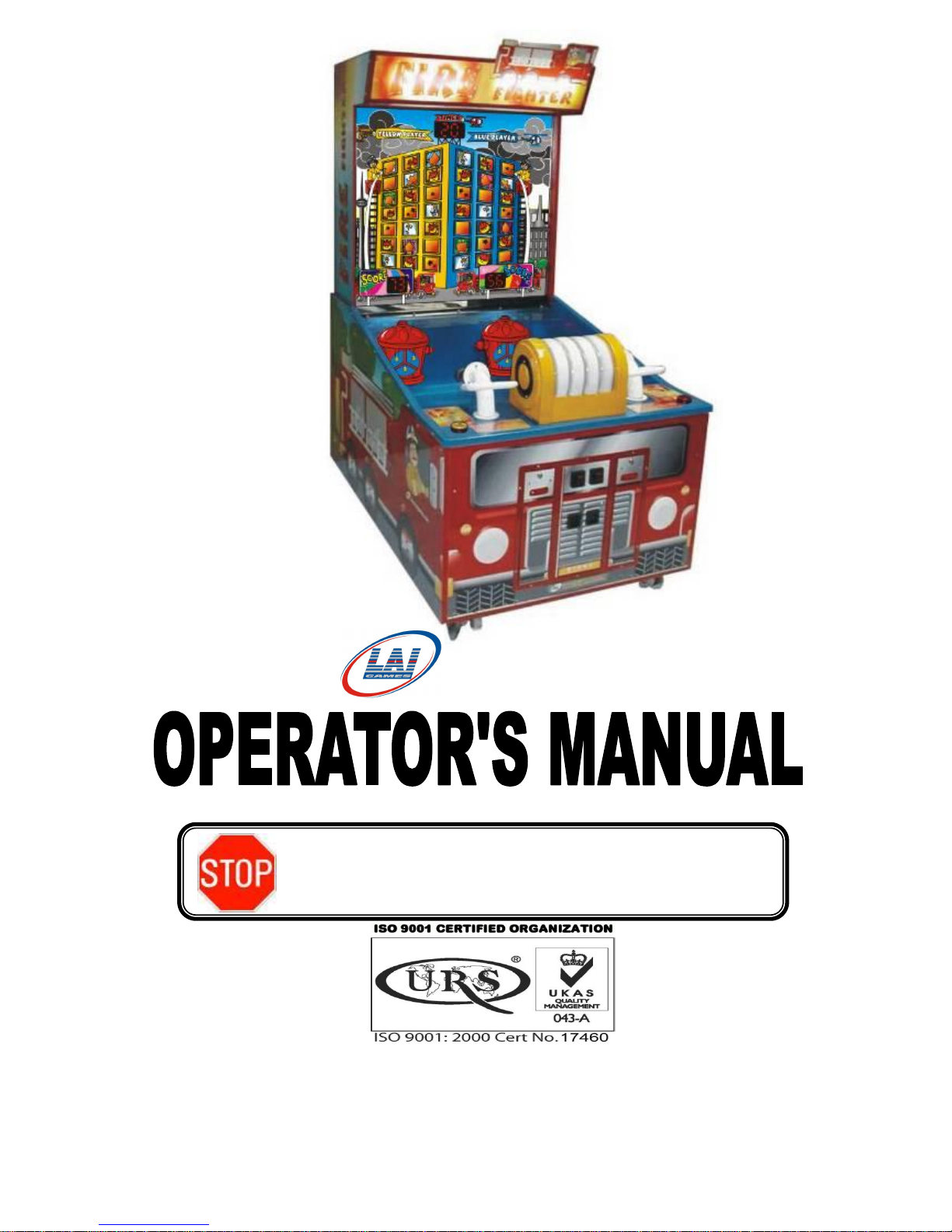
► READ THIS MANUAL BEFORE OPERATING THE MACHINE.
► KEEP THIS MANUAL FOR YOUR REFERENCE.
© LAI GAMES
www.laigames.com
Page 2
LAI GAMES
LAI GAMES
© LAI GAMES
Copyright Notice:
Authorization is hereby provided to you to copy this
manual in its entirety provided such copies are used for
non-commercial purposes and solely for use with LAI
GAMES products. This authorization is specifically
conditioned to include all legends, copyright, proprietary
and other notices which appear herein are unaltered on
any and all copies you make.
Correspondence regarding this machine should be addressed to your
closest LAI GAMES office, or LAI GAMES Distributor.
For contact details, refer to the back page of this manual.
DISCLAIMER
Please be aware that this software may not be legal to operate
in some states and countries. We are providing this software and hardware to you
on the understanding that you are installing it as per the regulatory requirements of
your location and that you or your company are fully responsible for any legal
problems that may arise from operating this version of software and hardware
Page 3

i
LAI GAMES NOTES
Dear Customer,
Keep up-to-date with any new Software release or Service Bulletins for
this Game.
Check our Website at www.laigames.com and click on Product Support,
here you will find links to all the Bulletins and Software Updates to keep
your game in top working order.
Thanks,
Page 4
Operator's Manual – FireFighter
© LAI GAMES
i
TABLE OF CONTENTS
SAFETY PRECAUTIONS .......................................................................................... 1
INTRODUCTION ..................................................................................................... 2
SPECIFICATIONS .................................................................................................... 3
MACHINE INSTALLATION AND INSPECTION ................................................... 4
ASSEMBLY INSTRUCTIONS ................................................................................. 5
WATER SYSTEM ..................................................................................................... 6
WATER SYSTEM DIAGRAM ................................................................................. 7
HOW TO PLAY ......................................................................................................... 8
OPERATION ............................................................................................................... 9
OPERATIONAL DIAGRAM .................................................................................. 9
ATTRACT MODE .................................................................................................. 9
PLAY MODE .......................................................................................................... 9
TEST MODE ........................................................................................................... 10
TEST MODE DIAGRAM ..................................................................................... 10
SOUND, LAMPS & DISPLAY TEST ................................................................... 11
SWITCH TEST ..................................................................................................... 11
RUN TEST ............................................................................................................ 13
PROGRAMMABLE ADJUSTMENTS MODE ...................................................... 14
PROGRAMMABLE ADJUSTMENTS MODE DIAGRAM................................... 14
PROGRAMMABLE ADJUSTMENTS PROCEDURE ......................................... 14
PROGRAMMABLE ADJUSTMENTS QUICK REFERENCE TABLE ................ 15
PROGRAMMABLE ADJUSTMENTS DETAILED .............................................. 16
AUDITS MODE ...................................................................................................... 18
AUDITS MODE DIAGRAM ................................................................................ 18
AUDIT PROCEDURE ......................................................................................... 19
AUDITS QUICK REFERENCE TABLE .............................................................. 20
AUDITS DETAILED ............................................................................................ 21
GAME HISTORY MODE ....................................................................................... 24
GAME HISTORY MODE DIAGRAM .................................................................. 24
GAME HISTORY QUICK REFERENCE TABLE ................................................ 24
GAME HISTORY PROCEDURE ......................................................................... 25
ERRORS AND TROUBLESHOOTING ................................................................. 26
FUSE INFORMATION ........................................................................................... 28
FUSE LOCATION DIAGRAM ............................................................................. 28
SECTION A: SERVICE INSTRUCTIONS ........................................................... 29
LOCATING AND ACCESSING PARTS ............................................................... 30
Page 5

Operator's Manual – FireFighter
© LAI GAMES
ii
PARTS LOCATION DIAGRAM ........................................................................... 30
LOCATING AND ACCESSING PARTS............................................................... 31
PARTS LOCATION DIAGRAM B ....................................................................... 31
PARTS DESCRIPTION ........................................................................................ 32
LAMPS .................................................................................................................... 34
MAINTENANCE .................................................................................................... 35
SECTION B: TECHNICAL DETAILS ................................................................... 36
MAINS VOLTAGE ADJUSTMENT ...................................................................... 37
TICKET DISPENSER REFERENCE GUIDE ........................................................ 39
BASIC OPERATION ............................................................................................ 39
SPECIFICATIONS ............................................................................................... 41
TD-963CR SCHEMATIC DIAGRAM .................................................................. 42
DISPENSER PARTS DIAGRAM.......................................................................... 43
3 D EXPLODE PARTS ............................................................................................ 44
FIREFIGHTER MAIN WIRING DIAGRAM ......................................................... 49
FIREFIGHTER BASE WIRING DIAGRAM ......................................................... 50
FIREFIGHTER POWER WIRING DIAGRAM ...................................................... 51
Page 6
Operator's Manual – FireFighter
© LAI GAMES
Page 1
SAFETY PRECAUTIONS
The following safety precautions and advisories are used throughout this manual and
are defined as follows.
BE SURE TO READ THE FOLLOWING
* WARNING! *
Disregarding this text could result in serious injury.
* CAUTION! *
Disregarding this text could result in damage to the machine.
* WARNING! *
Always turn OFF Mains AC power and unplugged the game, before
opening or replacing any parts.
Always when unplugging the game from an electrical outlet, grasp the
plug, not the line cord.
Always connect the Game Cabinet to grounded electrical outlet with a
securely connected ground line.
Do Not install the Game Cabinet outdoors or in areas of high humidity,
direct water contact, dust, high heat or extreme cold.
Do Not install the Game Cabinet in areas that would present an
obstacle in case of an emergency, ie. near fire equipment or emergency
exits.
* NOTE! *
An advisory text to hint or help understanding.
* CAUTION! *
Always use a Digital Multimeter, logic tester or oscilloscope for testing
integrated circuit (IC) logic PC boards. The use of a continuity tester is
not permitted.
Do Not Connect or disconnect any of the integrated circuit (IC) logic PC
boards while the power is ON.
Do Not use any fuse that does not meet the specified rating.
Do Not Subject the game cabinet to extreme temperature variations.
Reliability of electrical components deteriorates rapidly over 60 oC.
Page 7
Operator's Manual – FireFighter
© LAI GAMES
Page 2
INTRODUCTION
CONGRATULATIONS! You have just bought the “Fire Fighter”, another
sensational product from LAI GAMES. This game, based around the popular kids
water game style, has many new features. “Fire Fighter” features two player or single
player game play, an impressive main display, backlit targets, and robust and reliable
water Cannon guns. With its simple payout style, suited to children, we feel that “Fire
Fighter” will make a great game at any location, on or off site.
We hope you take the time to read this manual and learn about the many other features
and user-friendly adjustments that can be made to “fine-tune” the game for maximum
earning potential.
DESCRIPTION
The “Fire Fighter” is a one or two player, ticket redemption game, where players
attempt to beat their opponent (the second player in two player mode, a virtual
opponent if one player game) by putting out all the fires on the building levels. The
game also keeps an on-going score such that the first player to reach 99 points wins
the game.
PACKAGING
At delivery, the machine should arrive in good condition. To move the packaged
machine for transport or placement, use a forklift and take care not to hit the package
or stack heavy objects on top, as this may cause damage to the machine.
CONTENTS
The “Fire Fighter” lower cabinet
The “Fire Fighter” upper cabinet
Keys: 2 coin door keys
2 ticket door keys
2 back doors keys
2 ticket door keys
Operator‟s manual
IEC Power Cord (In cash box)
Parts & Accessories (In lower cabinet)
Page 8
Operator's Manual – FireFighter
© LAI GAMES
Page 3
SPECIFICATIONS
DIMENSIONS
Weight: 240 kg (530lb) [Empty of water]
Height: 2049mm (80-6/8”)
Width: 1082mm (42-1/2”)
Length: 1615mm (63-1/2”)
Power: Maximum 660 W – (220V @ 3.0 A)(120V @ 5.5 A)
Average 380 W – (220V @ 1.8 A)(120V @ 3.2 A)
ELECTRIC SUPPLY
The game has the option to operate on a 110V, 120V, 220V or 240V AC 50/60Hz
single phase mains electric supply.
The supply must be a three wire grounded supply.
LOCATION REQUIREMENTS
Ambient temperature: between 5oC and 40oC.
Ambient humidity: Low
Ambient U.V. radiation: Very low
Vibrations level: Low
* CAUTION! *
Before switching the machine on be sure to check that it has been set on the
correct voltage for your area!
Please Refer to the mains voltage adjustment section of this manual on page 37.
Machines are normally shipped on 220V AC unless otherwise specified.
Page 9
Operator's Manual – FireFighter
© LAI GAMES
Page 4
MACHINE INSTALLATION and INSPECTION
When installing and inspecting “Fire Fighter”, be very careful of the following points
and pay attention to ensure that the players can enjoy the game safely.
Be sure to turn the power OFF before working on the machine.
Make sure the power cord is not exposed on the surface (floor, ground, etc.) where
people walk through.
Check that the rubber glide feet levelers are set evenly on the floor so that the game
cabinet is unable to roll and is stable.
Always make complete connections for the integrated circuit (IC) logic PC Boards
and other connectors. Insufficient insertion can damage the electrical components.
Only qualified personnel should inspect or test the integrated circuit (IC) logic PC
Boards.
If any integrated circuit (IC) logic PC Boards should need servicing. Please contact
the nearest LAI GAMES distributor. (Refer to the back page of this manual)
* CAUTION! *
Before switching the machine on be sure to check that it has been set on the
correct voltage for your area!
Refer to the mains voltage adjustment section of this manual on page 37.
Machines are normally shipped on 220V AC unless otherwise specified.
* WARNING! *
Always Turn OFF mains power before removing safety covers and refit all safety
covers when work is completed.
* CAUTION! *
Water needs to be added to the game BEFORE running the pumps.
Prolonged dry running of the pumps can shorten their life.
See page 6 on how to fill and setup the water system.
Page 10
Operator's Manual – FireFighter
© LAI GAMES
Page 5
ASSEMBLY INSTRUCTIONS
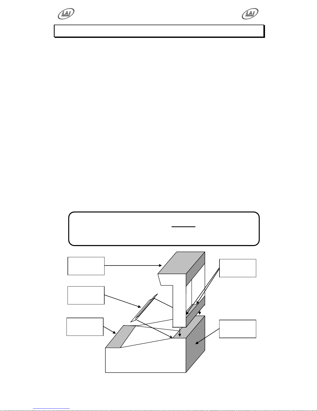
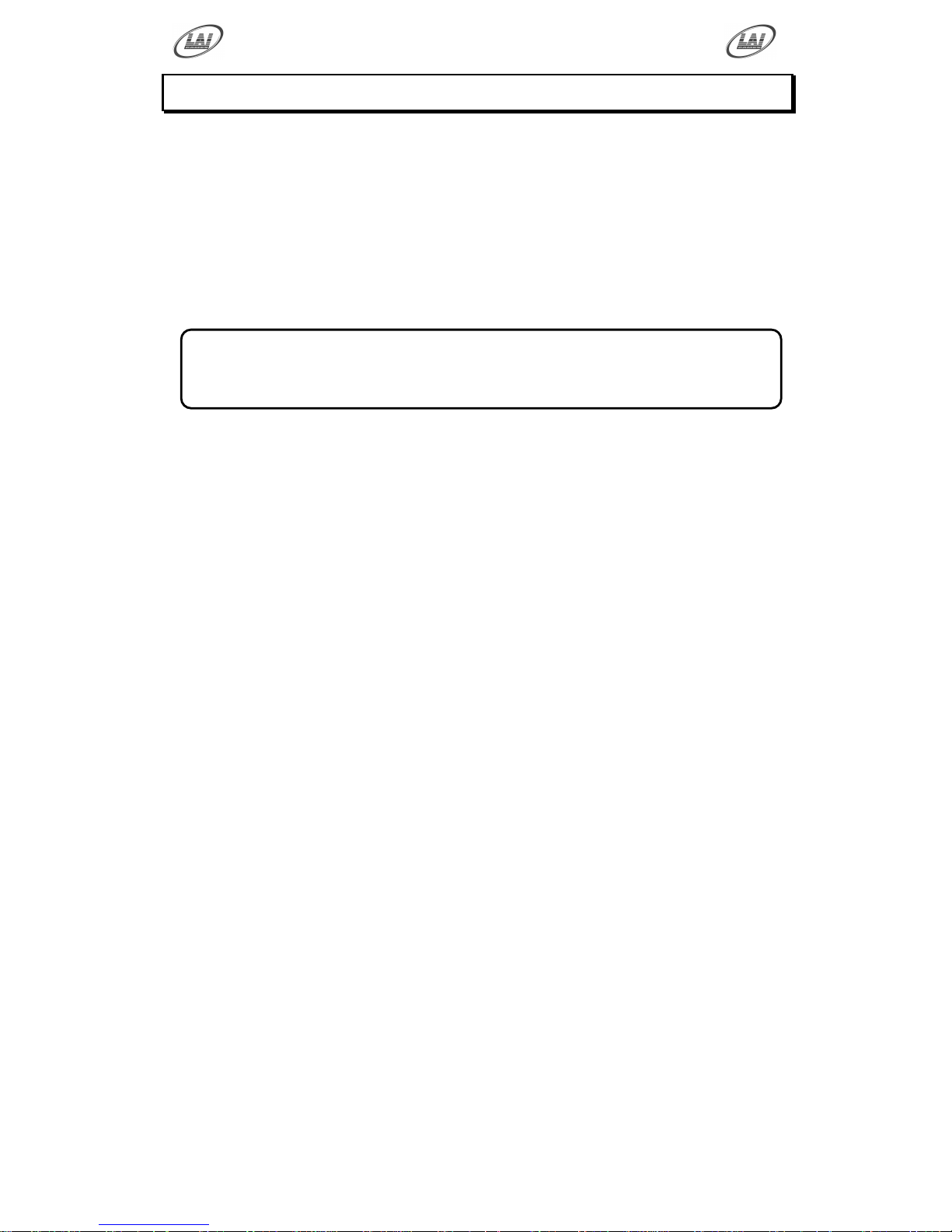
The “Fire Fighter” is shipped in two main sections, the Upper Cabinet, containing
most of the controlling electronics and the Lower Cabinet, containing the water system
and player controls. The game should not be shipped fully assembled as this could
cause damage to the Both Cabinets.
Position the Lower Cabinet nearby to its final location. The cabinet has four
heavy duty castors to allow easy repositioning of the game. Remove the four M12
x 80mm Bolts from the back mounting section and make sure it‟s clear of any
wires or obstructions.
Position the Upper Cabinet on the floor near the back of the Lower Cabinet
with the header facing the front. Unwrap and remove the back door of the Upper
Cabinet, this will give better grip when lifting the Upper Cabinet into place.
Using at least two persons, one at each side, lift the Upper Cabinet into position
on the Lower Cabinet. Using the four M12 x 80mm Bolts, mount the Upper
Cabinet tight to the Lower Cabinet.
Feed the Cables from the Upper Cabinet through the hole down into the Lower
Cabinet. Mate all the connectors together; they are keyed to prevent incorrect
connection. Remove the four Philip head screws from the red metal bracket just
above the Hydrant Targets. Position the Acrylic Splash Guard with the rubber
edging pressing up against the Display Glass and fit and tighten screws, don‟t
over tighten or it may crack the acrylic.
* CAUTION! *
Water needs to be added to the game BEFORE running the pumps.
Prolonged dry running of the pumps can shorten their life.
See page 6 on how to fill and setup the water system.
Upper
Cabinet
Lower
Cabinet
Splash
Guard
Mounting
Bolts
Cable
Connections
Page 11
Operator's Manual – FireFighter
© LAI GAMES
Page 6
WATER SYSTEM
The “Fire Fighter” is a water style game and requires regular maintenance and
cleaning to keep the water in good condition. The game needs 20 liters (5 Gallons) of
water to operate effectively. The machine should be emptied of any water before
moving or shipping to prevent spillage. The two 12Volt DC Pumps are able to run dry
for short durations without damage should the game accidentally be run without water.
A Stainless Steel grill between the water catchment and the water tank prevents large
objects from blocking the plumbing. A water filter protects the two pumps from fine
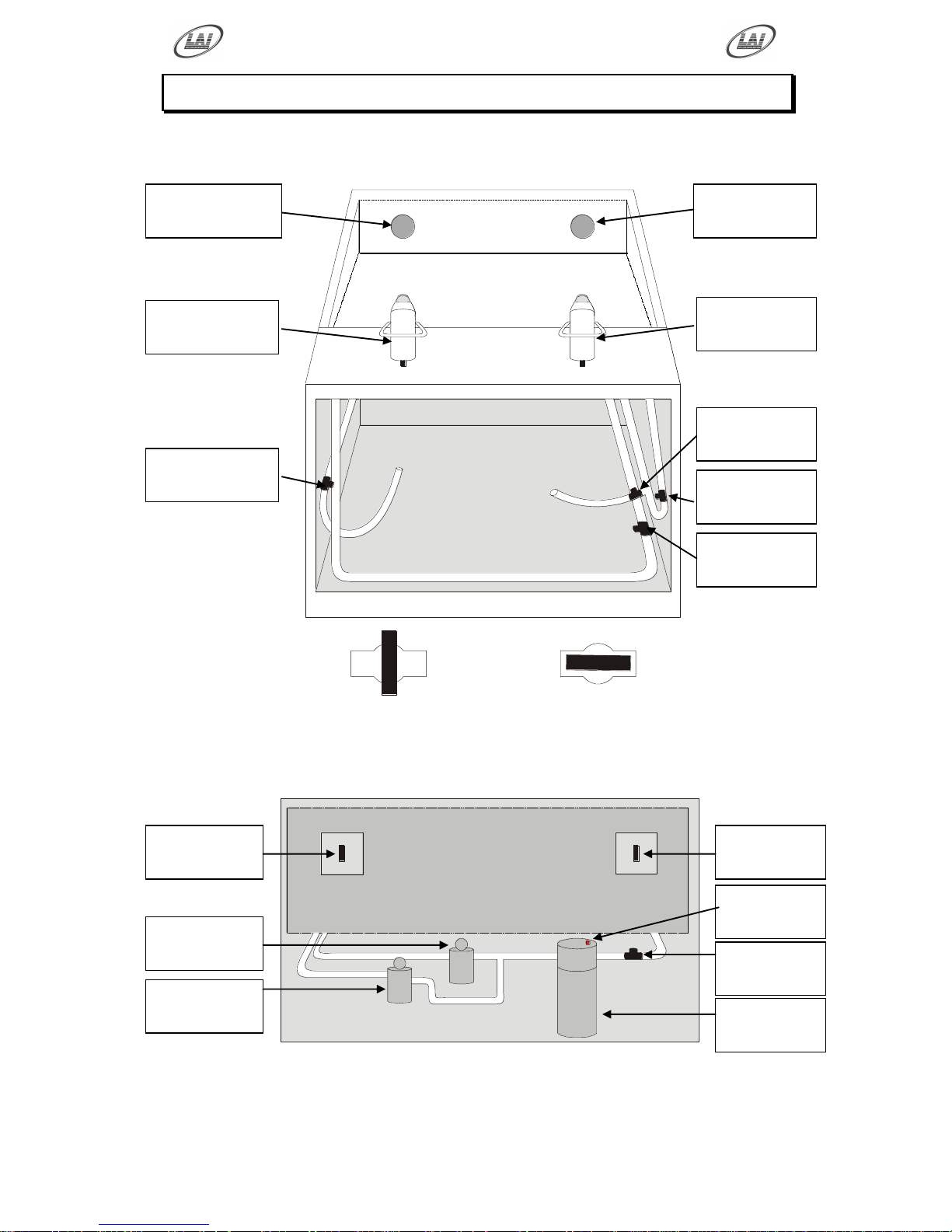
particle damage. Refer the Water System Diagrams on page 7 for locating water system
components and valves.
FILLING MACHINE
Check that the Drain Stop Valve is in the closed position (See page 7). Use a
bucket or metered container to fill the tank with 20 liters (5 Gallons) of clean tap
water. Open the Main Stop Valve at the back of the machine and then press the
small red filter bleed button on the top of the Water Filter to fill the filter with
water.
PRIMING PUMPS & ADJUST PRESSURE
Check that both the Yellow Player and Blue Player Stop Valves are open. Use
the Run Test Mode on page 13 to activate both Water Pumps. Let the water run
for a while to remove all air from the plumbing. Then with the Yellow Player /
Blue Player Stop Valves, as shown in the Water System Diagrams on page 7.
Slowly close off each valve to reduce the Canon water pressure so that the
targets can be moved and activate the target lights but the water stream is not
splashing excessively.
CLEANING OPERATIONS
The “Fire Fighter” is fitted with a Wash-Down Gun to help in cleaning the water
catchment area. To activate the Wash-Down Gun, Use the Run Test Mode on
page 13 to activate Pump 2 only. Then open the Wash-Down Gun Stop Valve,
use the trigger on the Gun and direct the water where needed. Be careful not to
splash water outside the fiberglass catchment area. You can close the Blue Player
Stop Valve if need be, but you will have to adjust the Canon water pressure again
when finished.
EMPTING MACHINE
Close the Main Stop Valve and then place the Drain Pipe at the front of the
machine in a bucket or suitable container. The containers height must be no
higher then 400mm (15”) to allow the tank to gravity drain. Use the Drain Stop
Valve to prevent overfilling of the container. Repeat until all water is drained
from the machine.
* NOTE! *
The addition of a small amount of pool chlorine to the water is recommended
to kill any algae or other organisms introduced during filling.
Page 12
Operator's Manual – FireFighter
© LAI GAMES
Page 7
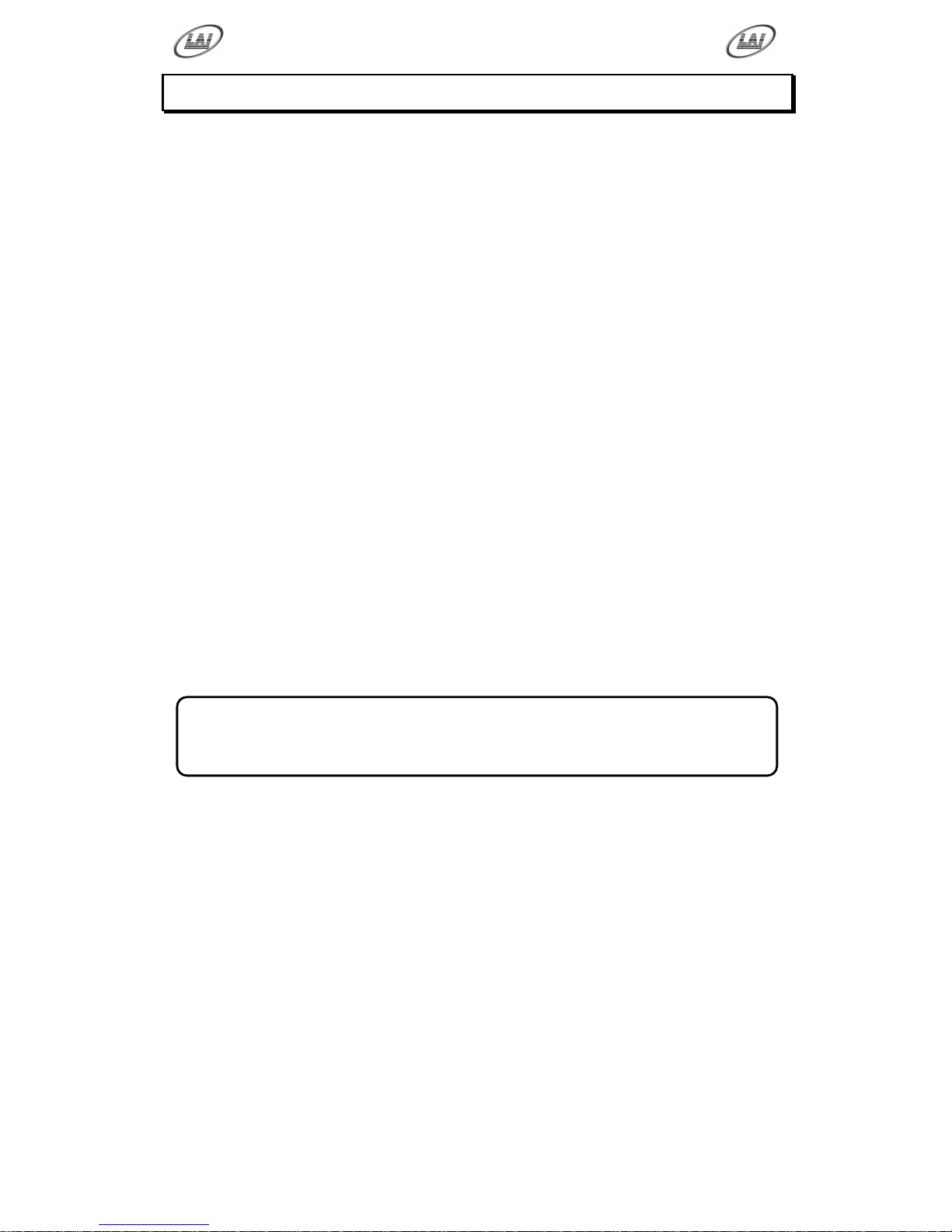
WATER SYSTEM DIAGRAM
As viewed from front
As viewed from rear
Yellow Player
Targets
Blue Player
Targets
Yellow Player
Water Canon
Blue Player
Water Canon
Drain Stop
Valve
Wash-Down
Stop Valve
Blue Player
Stop Valve
Yellow Player
Stop Valve
VALVE CLOSED
VALVE OPEN
Blue Player
Reed Switches
Yellow Player
Reed Switches
Blue Player
Pump
Filter Bleed
Button
Yellow Player
Pump
Main Stop
Valve
Water Filter &
Cartridge
Page 13
Operator's Manual – FireFighter
© LAI GAMES
Page 8
HOW TO PLAY
THE PLAYER’S AIM IS TO REACH THE 99 POINTS
FIRST BY AIMING THE WATER STREAM AT THE LIT
TARGETS INSIDE THE PLAYERS FIRE HYDRANT
Insert coin/s.
(The exact amount of coins per play is dependant on Program settings P1
through to P4. See program settings, page 14 for details).
For single player game, the player chooses to press ether the yellow or blue
player start button only. For a multi (two) player game both players must press
both the blue & yellow player start buttons together.
There is a brief build up period where the buildings are lit on fire. Then the
players fire hose(s) will start shooting water. Aim the stream of water at the
flashing targets inside the fire hydrant on your half of the playfield.
The fire in the building will start to reduce downwards while your score will
start rising as you hold your water stream on your targets.
(The exact amount of time you must hold your flashing targets in the active
position before a level of fire is turned off is controlled by P11. See Program
Settings, page 14 for details).
Once all the fires in the either building are put out (or the score reaches 99
points, as these always occur simultaneously) the game is then over. The side
that has put out all the levels (Or reached 99 points) is the winner.
(The skill level of the computer player in the one player game is controlled by
P12 setting. See Program Settings, page 14 for details).
Tickets are then dispensed.
(The amount of tickets is controlled by P7 through to P10. See Program
Settings, page 14 for details).
* NOTE! *
If the time out is reached then the side with the highest score is the winner.
(As set by P5, see Program settings Page 14 for details)
Page 14
Operator's Manual – FireFighter
© LAI GAMES
Page 9
OPERATION
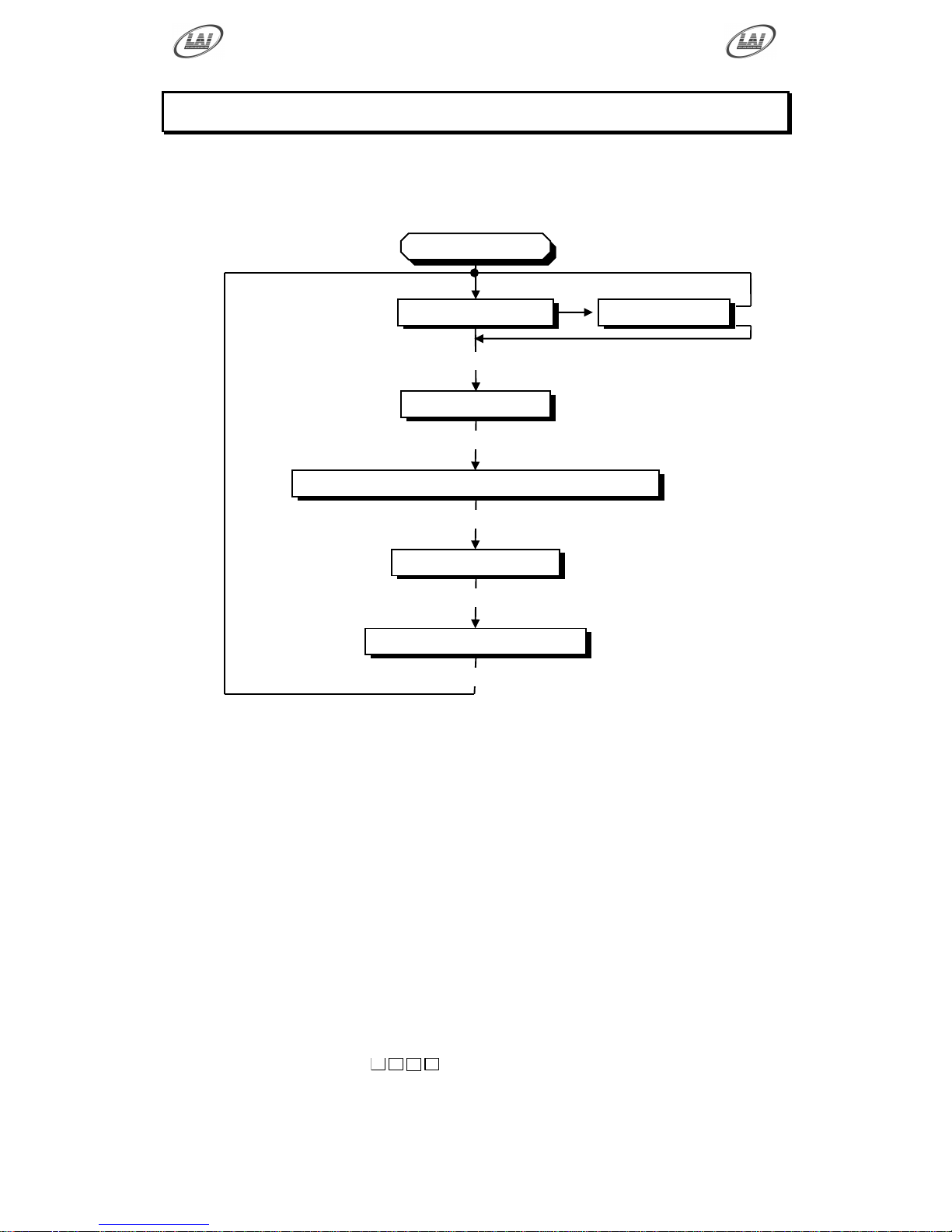
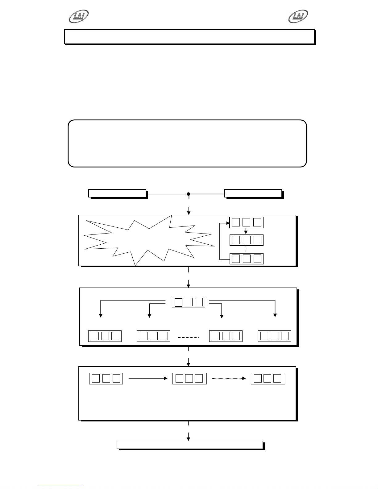
The “Fire Fighter” game has six operational modes: Attract mode, Play mode, Test
Mode, Programmable Adjustments Mode, Audits Mode and Game History Mode.
OPERATIONAL DIAGRAM
ATTRACT MODE
The Attract mode provides a light and sound display, while the game is not being
played. This feature is to attract potential customers to play the game. The attract
mode sound can be turned on and off
(Refer to programmable adjustment P07, see page 14 of this manual).
PLAY MODE
The Fire Fighter has two play modes. The Standard Coin Play mode, where a
coin, or coins are inserted. Or Free Play where no coins are necessary.
COIN PLAY
The Coin Play mode is entered from Attract mode, by inserting coins in any of the
two coin slots on the front of the machine cabinet, then following the instructions
in the “How to Play” section of this manual.
FREE PLAY
The free play mode is entered from attract mode by holding the Service button for
longer than five second,
F r r
E
will be displayed on the 3-digit LED display.
To get back to normal game Play mode Switch Off and On the Machine.
POWER UP
ATTRACT MODE
PLAY MODE
TEST MODE
PRESS TEST
AUDITS MODE
PRESS TEST
PROGRAMMABLE ADJUSTMENTS MODE
PRESS TEST
GAME HISTORY MODE
PRESS TEST
PRESS TEST
* NOTE! *
Entering test mode will
clear any stored credits
Page 15
Operator's Manual – FireFighter
© LAI GAMES
Page 10
PROGRAMMABLE ADJUSTMENTS MODE
PLAY MODE
The Displays count,
the building lamps flash, all the other
lamps flash and sound is played
ATTRACT MODE
1
1
9
9 1 9
0 0 C
0 1 C 0 2 C 1 2 C - 1
3
0 0 0 0 1 r rrr 0 4
r
PUMP MOTOR TEST
R01. Run yellow player water pump only
R02. Run blue player water pump only
R03. Run both yellow & blue player water pumps
R04. Both of water pumps OFF
TEST MODE
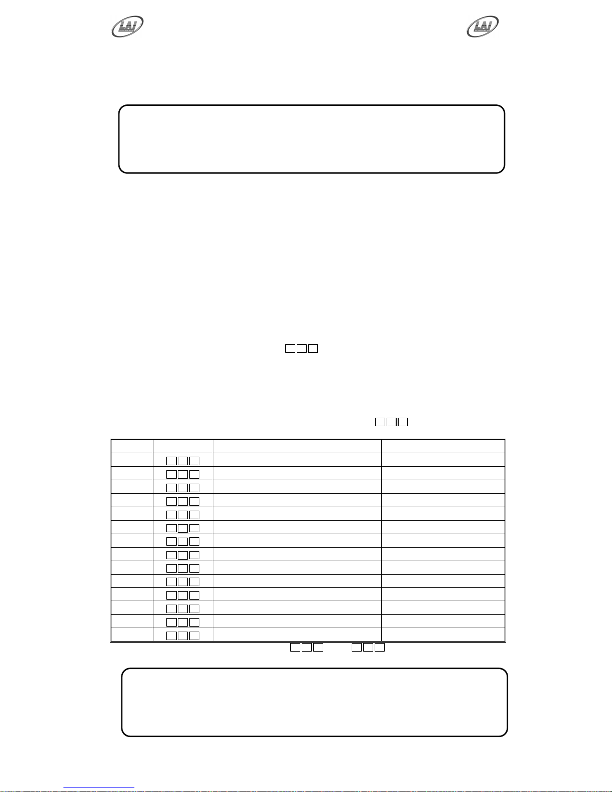
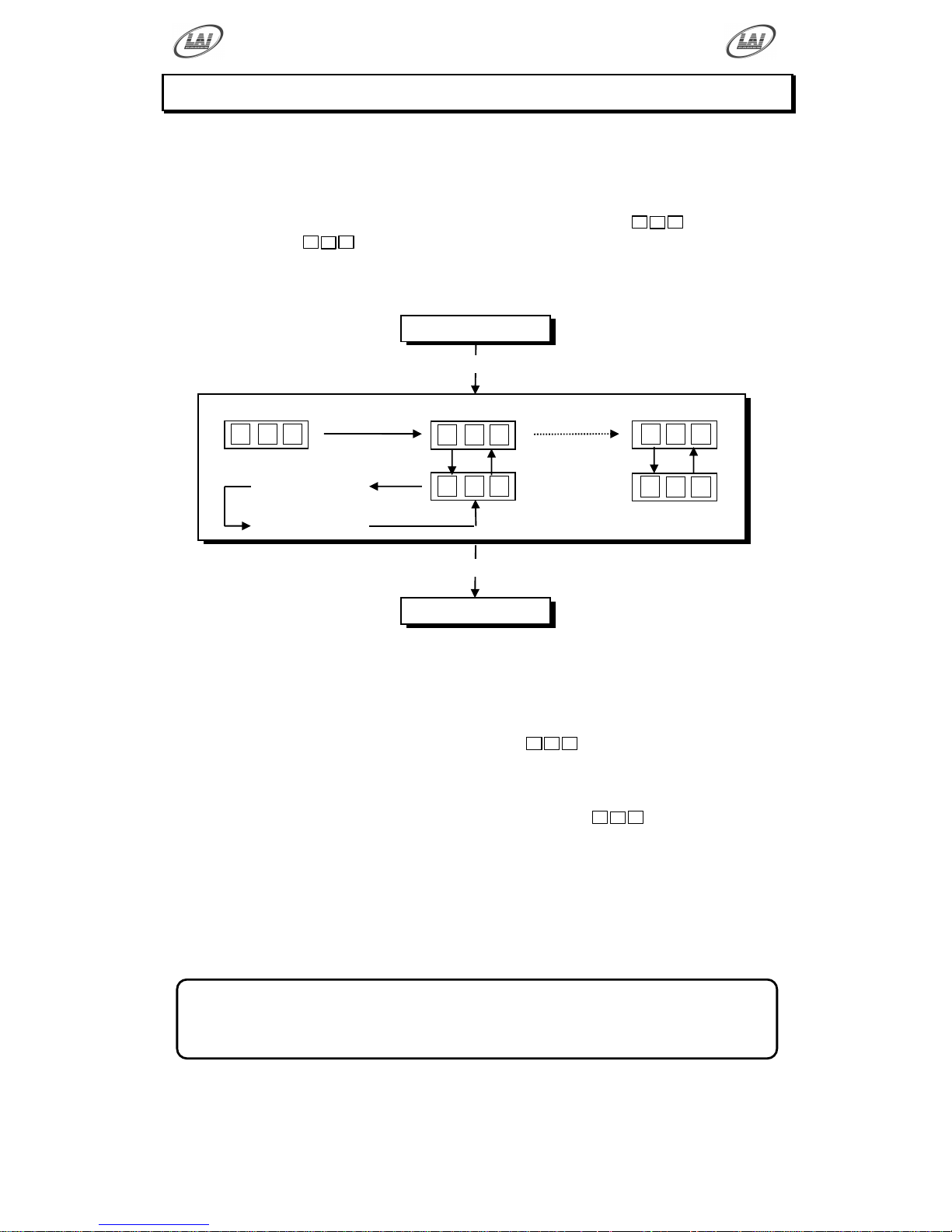
The Fire Fighter Test mode has Three Test Configurations allowing you to test the
function of the Sound, all Game Lamps, Displays, the Game Switches, Pump Motors
and the Water Cannon action. (Refer to the Test Mode Diagram below).
The Test mode is also used for Clearing Game Errors. If there is an active error, its
code will be displayed. To try to clear the error code, press the red test button once.
The error can be bypass by quickly pressing the red test button twice.
(For Game Errors codes, refer to page 26).
TEST MODE DIAGRAM
* NOTE! *
Entering Test Mode will CLEAR any CREDITS remaining in the game.
If during test mode no ADJUSTMENTS or actions are made to the game for
approximately four minutes, it will automatically RETURN to Attract Mode.
SOUND, LAMPS & DISPLAY TEST
No INPUT is active
TARGET 3
Blue Player active
TICKET notch
Yellow Player active
TICKET notch
Blue Player active
TARGET 2
Blue Player active
To
PRESS TEST
PRESS TEST
SWITCH INPUT TEST
PRESS TEST
PRESS TEST
RUN TEST
PRESS
SERVICE
PRESS
SERVICE
REPEATEDLY
To step from
R01 to R04
Loops back
to R01
Page 16
Operator's Manual – FireFighter
© LAI GAMES
Page 11
SOUND, LAMPS & DISPLAY TEST
ENTER The Sound, Lamp & Display test is entered from Attract mode by
pressing the test button once.
DURING THE TEST:
o Game music and a voice over will be played.
o The backlighting of the buildings will light up level by level.
o All the displays will count from 000 to 999 and then repeat.
o The Yellow Player and Blue Player button lamps will flash on and off.
o The target back lights will light up.
EXIT The Sound, Lamp & Display test is exited by pressing the test button.
The next test will be switch test.
SWITCH TEST
ENTER The Switch Test can be entered by pressing the Test button once while
in the Sound, Light & display test or by pressing the Test button twice
while in Attract mode,
C X X
will be displayed on the 3-digit display
where „XX‟ is a number representing the switch that is active.
TESTING THE GAME SWITCHES
All game switches have a code from C1 to C13 as tabled below. By
activating any of the switches, their code will be displayed on the 3digit display. If no switches are active then
C 0 0
will be displayed.
CODE
DISPLAY
SWITCH FUNCTION
SWITCH LOCATION
C0
C 0 0
No Switch Active
-
C1
C 0 1
Ticket Notch Yellow Player Active
Left Hand Ticket Door
C2
C 0 2
Ticket Notch Blue Player Active
Right Hand Ticket Door
C3
C 0 3
Service Switch Active
Service Panel
C4
C 0 4
Yellow Player Start Button Active
Control Panel
C5
C 0 5
Blue Player Start Button Active
Control Panel
C6
C 0 6
Coin 1 Switch Active
Coin Door
C7
C 0 7
Coin 2 Switch Active
Coin Door
C8
C 0 8
Target 1 Yellow Player Active
Cabinet Back
C9
C 0 9
Target 2Yellow Player Active
Cabinet Back
C10
C 1 0
Target 3 Yellow Player Active
Cabinet Back
C11
C 1 1
Target 1 Blue Player Active
Cabinet Back
C12
C 1 2
Target 2 Blue Player Active
Cabinet Back
C13
C 1 3
Target 3 Blue Player Active
Cabinet Back
Normal condition for the game is
C 0 1
and
C 0 2
indicating that the ticket
mechanism sensors are active
* NOTE! *
If there is an active error displayed, press the red test button once to try and
clear the error. If the error code will not clear, it can be bypass by quickly
pressing the red test button twice.
* NOTE! *
Several switches can be simultaneously activated in Switch test. The display
will then consecutively show their codes, indicating which switches are
active. However, it is much easier to test the game switches individually.
Page 17
Operator's Manual – FireFighter
© LAI GAMES
Page 12
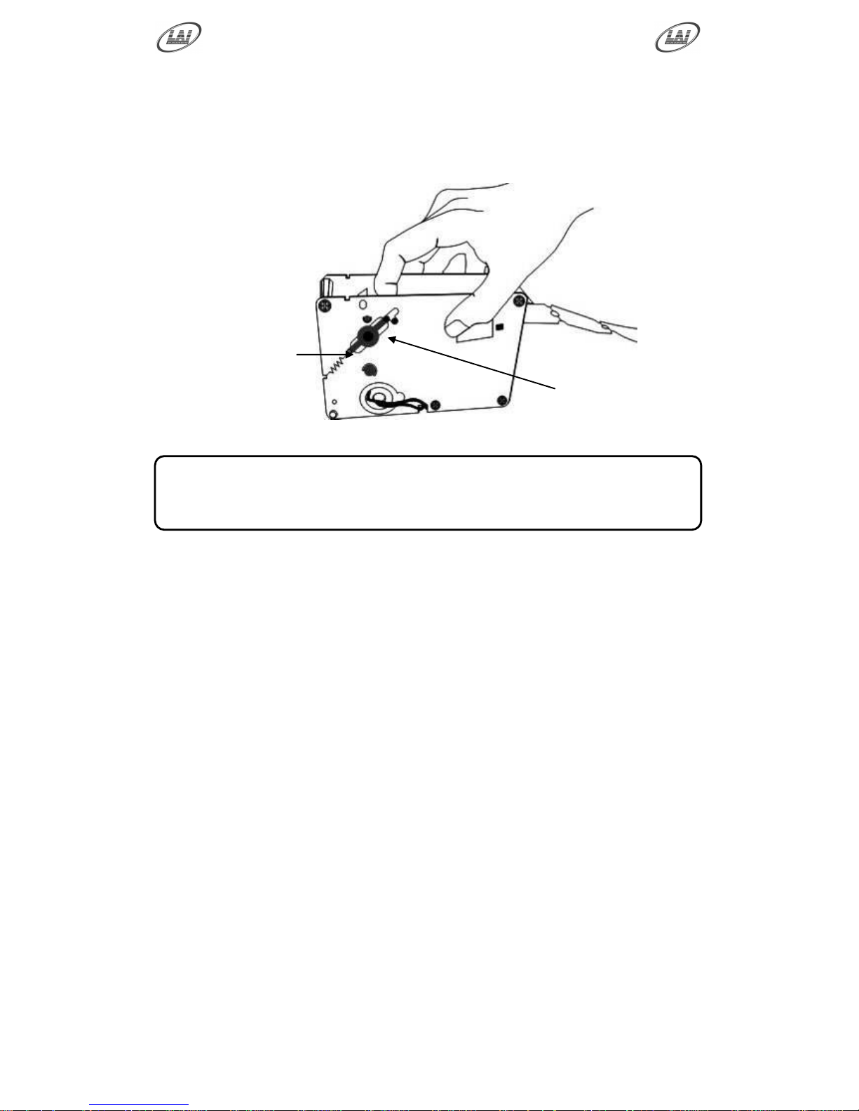
TICKET DISPENSER NOTCH
The Ticket Notch Switch (C1 & C2) can be activated or deactivated from the
Ticket Feed Button on the Ticket Dispenser PCB or by manually pushing the
tickets from the ticket holder through the dispenser after pulling the ticket release
rod upwards
EXIT The Switch Test is exited into Run Test Mode by pressing the Test
Button once.
Ticket Tensioning
mechanism
Ticket release rod
* NOTE! *
For more information on the servicing and testing the ticket
dispenser please look at the Dispenser Reference guide.
Page 18
Operator's Manual – FireFighter
© LAI GAMES
Page 13
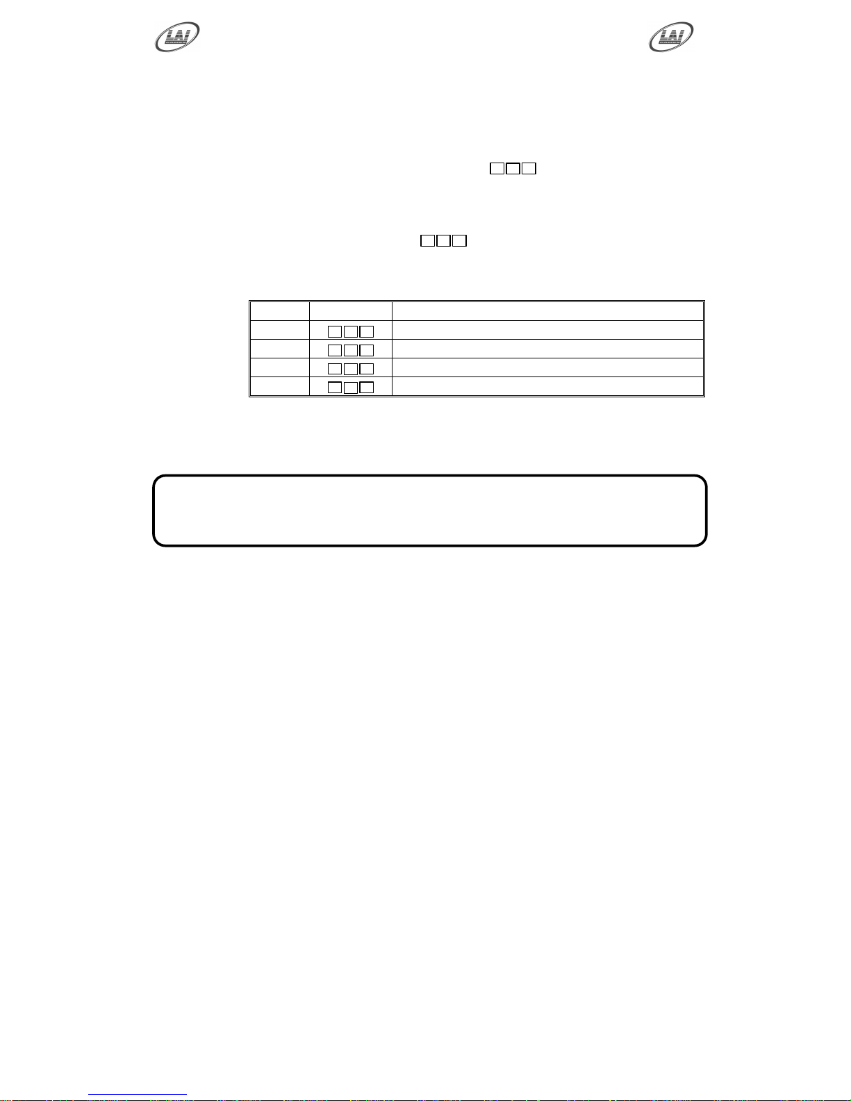
RUN TEST
ENTER The Run Test mode is entered from switch test by pressing the Test
button once or from Attract mode by pressing the Test button three
times. This will prompt the code
r r r
on the 3-digit display
indicating the program mode.
SELECT The Service button is pressed to step through each of the run test
modes, starting from the
r 0 1
display, R01 being the first step,
continuing through to R04, and then looping again from R01 to R04
until the mode is exited
EXIT The Run Test is exited into Programmable Adjustments Mode by
pressing the Test Button once.
CODE
DISPLAY
RUN TEST FUNCTION
R01
r 0 1
Run Yellow Player Water Pump
R02
r 0 2
Run Blue Player Water Pump
R03
r 0 3
Run Yellow & Blue Player Water Pumps
R04
r 0 4
Both Water Pumps inactive
* NOTE! *
If any of the games target sensors become active,
then the corresponding target‟s backlight will activate.
Page 19
Operator's Manual – FireFighter
© LAI GAMES
Page 14
PRESS START
to change value
1, 2, 3, 4 … 10
P 0 1
P P P 1 3 P 1
5
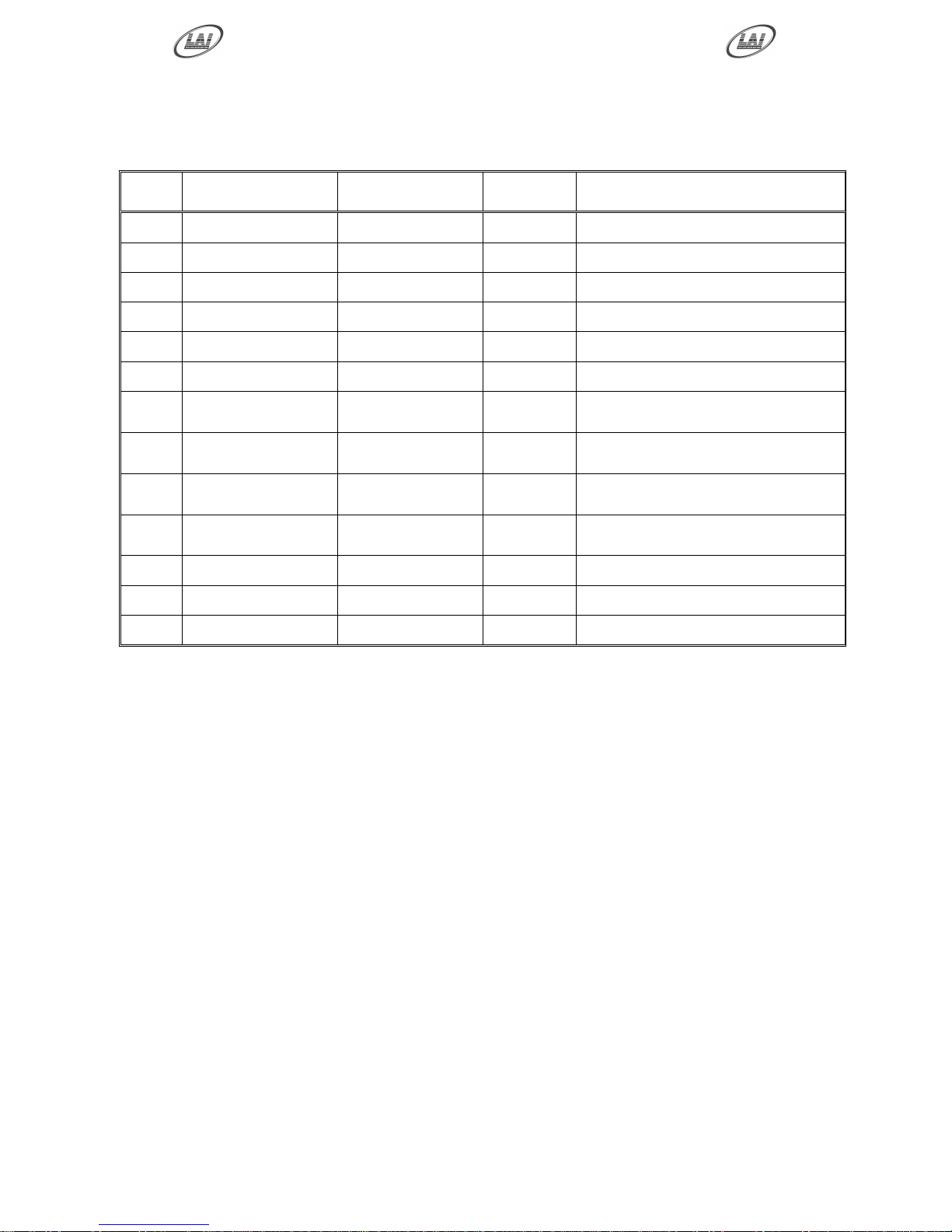
PROGRAMMABLE ADJUSTMENTS MODE
The Fire Fighter has thirteen programmable adjustments that can be changed in this
mode. They are P01 to P13 and their codes and values are displayed alternatively
during the adjustment procedure.
Example: Code P01 (Number of Coins Mech 1) is displayed as
P 0 1
and its value
of 1 as
1
on the 3-digit display.
PROGRAMMABLE ADJUSTMENTS MODE DIAGRAM
PROGRAMMABLE ADJUSTMENTS PROCEDURE
ENTER The Programmable Adjustments Mode can be entered by pressing the
Test button once while in the Run Test or by pressing the Test button
four times while in Attract mode,
P P P
will be displayed on the 3-
digit credit display.
SELECT The green Service button is pressed to step through each of the
adjustment configurations, starting from the
P P P
display, P01 being
the first step, continuing through to P13, and then looping again from
P01 to P13 until the mode is exited.
CHANGE The Yellow Player Start button is pressed to change the displayed
value. The value can only be stepped up by using the Start button, but
the value will loop back to its minimum value the next step after its
max value.
EXIT The Programmable Adjustments mode is exited into Audits mode, by
pressing the Test button once.
RUN TEST MODE
PRESS TEST
PROGRAMMABLE ADJUSTMENTS MODE
PRESS
SERVICE
PRESS
SERVICE
REPEATEDLY
To step from
P01 to P13
AUDIT MODE
PRESS TEST
* NOTE! *
Certain program adjustments have a fast adjustment feature.
By holding the Start button down, the values step through quicker.
Loops back to P01
Page 20
Operator's Manual – FireFighter
© LAI GAMES
Page 15
PROGRAMMABLE ADJUSTMENTS QUICK
REFERENCE TABLE
CODE
PROGRAMMABLE
ADJUSTMENTS
OPTIONAL
VALUES
DEFAULT
SETTINGS
FEATURES
P01
1 – 10
1, 2, 3…10
1
Coin Slot 1 – Coins / Credit
P02
1 – 10
1, 2, 3…10
1
Coin Slot 1 – Games / Credit
P03
1 – 10
1, 2,3 …10
1
Coin Slot 2 – Coins / Credit
P04
1 – 10
1, 2,3 …10
1
Coin Slot 2 – Games / Credit
P05
30 – 300
30,40,50…300
80
Maximum Game Time
P06
0n – Off
0n, Off
On
Attract Sound On/Off
P07
0– 100
0, 1, 2, 3…100
12
Number of Tickets
Single Player Game Winner
P08
0– 100
0, 1, 2, 3…100
6
Number of Tickets
Single Player Game Loser
P09
0– 100
0, 1, 2, 3…100
18
Number of Tickets
Multi Player Game Winner
P10
0 – 100
0, 1, 2, 3…100
10
Number of Tickets
Multi Player Game Loser
P11
1 –10
1, 1.5,2.5 …10
2.5
Seconds per Building Level
P12
1 – 20
1, 2, 3, … 20
10
Computer Player Skill Level
P13
1 – 10
1, 2, 3, … 10
5
Target Hardness Level
Note: All default settings are for an average of 11 tickets per game.
Page 21

Operator's Manual – FireFighter
© LAI GAMES
Page 16
PROGRAMMABLE ADJUSTMENTS DETAILED
P01=COIN MECH 1: NUMBER OF COINS PER CREDIT
(Default 01) (Adjustable 1 – 10)
This variable sets the number of coins that need to be inserted into coin
mechanism 1, for each credit. It can be set to either of 1, 2, 3… to 10 coins for one
credit.
P02=COIN MECH 1: NUMBER of PLAYS PER CREDIT
(Default 01) (Adjustable 1 – 10)
This sets the number of games for each credit inserted into coin mechanism 1. It
can be set to either of 1, 2, 3… to 10 plays for each credit.
P03=COIN MECH 2: NUMBER OF COINS PER CREDIT
(Default 01) (Adjustable 1 – 10)
This variable sets the number of coins that need to be inserted into coin
mechanism 2 for each credit. It can be set to either of 1, 2, 3… to 10 coins for one
credit.
P04=COIN MECH 2: NUMBER of PLAYS PER CREDIT
(Default 01) (Adjustable 1 – 10)
This sets the number of games for each credit inserted into coin mechanism 2. It
can be set to either of 1, 2, 3… to 10 plays for each credit.
P05 = MAXIMUM GAME TIME
(Default 80) (Adjustable 30s-300s)
This option adjusts the number of seconds before the game will time out and shut
itself down. This is intended purely as a safety measure, in case of a blocked
pump causing the game to run continuously (as the sensor would not be activated)
or a player who starts a game then walks away.
P06 = ATTRACT MODE SOUND
(Default ON) (Adjustable ON or OFF)
This adjustment turns the attract mode sound ON or OFF. This is the sound and
music that the game generates to attract customers when it is not being played.
The music will cycle approximately every 3 minutes.
P07= NUMBER OF TICKETS SINGLE PLAYER GAME WINNER
(Default 12) (Adjustable from 0 to 100)
This setting is the number of tickets the game dispenses when a player who has
played a single player game wins the game by putting out all the fires (reaching 99
points) before the computer controlled player does.
Page 22

Operator's Manual – FireFighter
© LAI GAMES
Page 17
P08= NUMBER OF TICKETS SINGLE PLAYER GAME LOSER
(Default 6) (Adjustable from 0 to 100)
This setting is the number of tickets the game dispenses when a player who has
played a single player game loses the game because the computer controlled
player by puts out all the fires (reaching 99 points) before the player does.
P09= NUMBER OF TICKETS MULTI PLAYER GAME WINNER
(Default 18) (Adjustable from 0 to 100)
This setting is the number of tickets the game dispenses when a player who has
played a multi player game wins the game by putting out all the fires (reaching 99
points) before the other player does.
P10= NUMBER OF TICKETS MULTI PLAYER GAME LOSER
(Default 10) (Adjustable from 0 to 100)
This setting is the number of tickets the game dispenses when the player who has
played a multi player game loses the game because the other player by puts out all
the fires (reaching 99 points) before the player does.
P11 = SECONDS PER BUILDING LEVEL
(Default 2.5) (Adjustable from 1 to 10)
This setting is the number of seconds the target sensors must be active for the fire
in the building to drop by 1 level. There are 7 building levels in each game.
P12 = COMPUTER PLAYER SKILL LEVEL
(Default 10) (Adjustable 1 to 20)
This adjustment controls the skill level of the computer player in the single player
game. In the single player game, the player plays against a virtual opponent,
controlled by the micro-controller. Altering this option higher make the computer
player a better player, decreasing the chances of a player winning the single player
game. Conversely, altering this option lower will make the computer player
worse, increasing the changes of a player playing the single player game wining.
P13 = TARGET HARDNESS LEVEL
(Default 5) (Adjustable from 1 to 10)
This setting controls the Target Hardness Level by changing the active position
between each of the three targets in the hydrant. Increasing this setting increases
the number of times that active target is changed. Decreasing the setting slows
down the change in active targets.
Page 23
Operator's Manual – FireFighter
© LAI GAMES
Page 18
Displays CODE then VALUE
or if value < 999
Displays CODE, upper VALUE
Then lower VALUE
A 0 1
A A A 1 6 A6 0 4 2 1 5 8 9 1
2
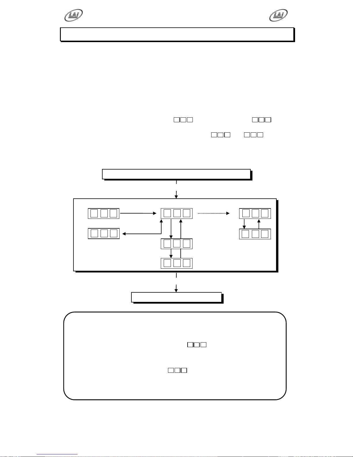
AUDITS MODE
The Audits Mode allows the operator to view statistics in all areas of the Game Play.
This enables the operator to make calculated adjustments and “Fine Tune” the
machine to maximize earning potential. The Audits mode stores bookkeeping of the
games processed since the last game audits reset. While in this mode, the game audits
can also be reset to zero.
The Fire Fighter has sixteen Audits that can be viewed in this mode. They are A01 to
A16 and their codes and values are displayed alternatively during the Audit Mode.
Example: Code A01 will be displayed as
A 0 1
and a value of 421 as
4 2 1
on the
3-digit display.
Or it will display large values like 21589 as
-
1
2
and
5 8 9
on the 3-
digit display.
AUDITS MODE DIAGRAM
PROGRAMMABLE ADJUSTMENTS MODE
PRESS TEST
AUDITS MODE
PRESS
SERVICE
PRESS
SERVICE
REPEATEDLY
To step from
A01 to A16
GAME HISTORY MODE
PRESS TEST
Loops back to A01
Press and hold START button
for 5 seconds to reset All Audits
* NOTE! *
For Audit values that are greater than 999 the audits‟ values will be
displayed in two steps.
The first number, which is displayed as
-
1
2
, has leading dash symbols
(-). The number displayed here must by multiplied by 1,000 and added to
the second value.
The second value is displayed as
5 8 9
, which has no dash symbols.
In this example the final value is 21,589
Page 24
Operator's Manual – FireFighter
© LAI GAMES
Page 19
AUDIT PROCEDURE
ENTER The Audits mode is entered from Programmable Adjustments mode by
pressing the Test button once or from Attract mode by pressing the
Test button five times.
A A A
will be displayed on the 3-digit display.
SELECT The green Service button is pressed for advancing each step through
the set of audits configurations, starting from the
A A A
display, A01
being the first step, continuing through to A16, and then looping again
from A01 to A16 until the mode is exited.
RESET The entire set of user audits can be reset during any of the audit
configurations, by holding the Yellow Start button for longer than 5
seconds. The displays will be cleared while still holding the button
pressed and will return to the same audit step after releasing the button.
The value of all audits will be reset to “00 000”.
EXIT The Audits mode is exited into Game History mode, by pressing the
Test button once.
* NOTE! *
ALL Audits will STOP INCREMENTING when the
“Total Number of Games Played”, audit A-01, reaches 60,000.
To restart the audits they must be reset to 00 000 by holding
The Start button for longer than 5 seconds while in audits mode.
Page 25
Operator's Manual – FireFighter
© LAI GAMES
Page 20
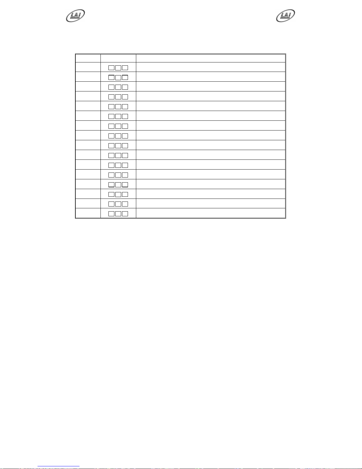
AUDITS QUICK REFERENCE TABLE
CODE
DISPLAY
AUDIT FUNCTION
A01
A 0 1
Total Number of Games Played
A02
A 0 2
Total Number of Single Player Games
A03
A 0 3
Total Number of Multi Player Games
A04
A 0 4
Total Number of Yellow Player Games
A05
A 0 5
Total Number of Blue Player Games
A06
A 0 6
Total No. of times a Single Player on Yellow Won
A07
A 0 7
Total No. of times a Single Player on Yellow Lost
A08
A 0 8
Total No. of times a Single Player on Blue Won
A09
A 0 9
Total No. of times a Single Player on Blue Lost
A10
A 1 0
Total No. of times Multi Players on Yellow Won
A11
A 1 1
Total No. of times Multi Players on Yellow Lost
A12
A 1 2
Total No. of times Multi Players on Blue Won
A13
A 1 3
Total No. of times Multi Players on Blue Lost
A14
A 1 4
Total Coins In Mechanism 1
A15
A 1 5
Total Coins In Mechanism 2
A16
A 1 6
Total Number of Service Credits
Page 26

Operator's Manual – FireFighter
© LAI GAMES
Page 21
AUDITS DETAILED
A01 = TOTAL NUMBER OF GAMES PLAYED
This Audit displays the total number of games played on this machine since the
audits were last cleared (including service games).
A02 = TOTAL NUMBER OF SINGLE PLAYER GAMES
This Audit displays the Total Number of Single Player Games started since the
audits were last cleared. Single Player mode is selected by pressing Only the
Yellow or Blue Start buttons on the control panel at the start of a game.
A03 = TOTAL NUMBER OF MULTI PLAYER GAMES
This Audit displays the Total Number of Multi Player Games started since the
audits were last cleared. Multi Player mode is selected by pressing Both the Yellow
and Blue Start buttons on the control panel at the start of a game.
A04 = TOTAL NUMBER OF YELLOW PLAYER GAMES
This Audit displays the total number of yellow player games Started since the audits
were last cleared. This Audit counts every game started using the yellow start
button both for single or multi player games.
A05 = TOTAL NUMBER OF BLUE PLAYER GAMES
This Audit displays the total number of blue player games Started since the audits
were last cleared. This Audit counts every game started using the blue start button
both for single or multi player games.
A06 = TOTAL NUMBER OF TIMES A SINGLE PLAYER ON
YELLOW WON
This Audit displays the total number times a player on yellow has won in the single
player mode since the audits were last cleared. Single Player mode is selected by
pressing Only the Yellow or Blue Start buttons on the control panel at the start of a
game.
A07 = TOTAL NUMBER OF TIMES A SINGLE PLAYER ON
YELLOW LOST
This Audit displays the total number times a player on yellow has lost in the single
player mode since the audits were last cleared. Single Player mode is selected by
pressing Only the Yellow or Blue Start buttons on the control panel at the start of a
game.
A08 = TOTAL NUMBER OF TIMES A SINGLE PLAYER ON
BLUE WON
This Audit displays the total number times a player on blue has won in the single
player mode since the audits were last cleared. Single Player mode is selected by
pressing Only the Yellow or Blue Start buttons on the control panel at the start of a
game.
Page 27

Operator's Manual – FireFighter
© LAI GAMES
Page 22
A09 = TOTAL NUMBER OF TIMES A SINGLE PLAYER ON
BLUE LOST
This Audit displays the total number times a player on blue has lost in the single
player mode since the audits were last cleared. Single Player mode is selected by
pressing Only the Yellow or Blue Start buttons on the control panel at the start of a
game.
A10 = TOTAL NUMBER OF TIMES MULTI PLAYERS ON
YELLOW WON
This Audit displays the total number times a player on yellow has won in the multi
player mode since the audits were last cleared. Multi Player mode is selected by
pressing Both the Yellow and Blue Start buttons on the control panel at the start of
a game.
A11 = TOTAL NUMBER OF TIMES MULTI PLAYERS ON
YELLOW LOST
This Audit displays the total number times a player on yellow has lost in the multi
player mode since the audits were last cleared. Multi Player mode is selected by
pressing Both the Yellow and Blue Start buttons on the control panel at the start of
a game.
A12 = TOTAL NUMBER OF TIMES MULTI PLAYERS ON
BLUE WON
This Audit displays the total number times a player on blue has won in the multi
player mode since the audits were last cleared. Multi Player mode is selected by
pressing Both the Yellow and Blue Start buttons on the control panel at the start of
a game.
A13 = TOTAL NUMBER OF TIMES MULTI PLAYERS ON
BLUE LOST
This Audit displays the total number times a player on blue has lost in the single
player mode since the audits were last cleared. Multi Players mode is selected by
pressing Both the Yellow and Blue Start buttons on the control panel at the start of
a game.
A14 = TOTAL NUMBER COINS IN MECHANISM 1
This Audit displays the total number of coins inserted into coin mechanism 1 since
the audits were last cleared.
A15 = TOTAL NUMBER COINS IN MECHANISM 2
This Audit displays the total number of coins inserted into coin mechanism 2 since
the audits were last cleared.
Page 28
Operator's Manual – FireFighter
© LAI GAMES
Page 23
A16 = TOTAL NUMBER SERVICE CREDITS.
This Audit displays the total number of service credits that were given since the
audits were last cleared.
* NOTE! *
LAI Games Customer Support may request from the operator the values of
these Manufacturers audits, to help with any service issues.
Page 29
Operator's Manual – FireFighter
© LAI GAMES
Page 24
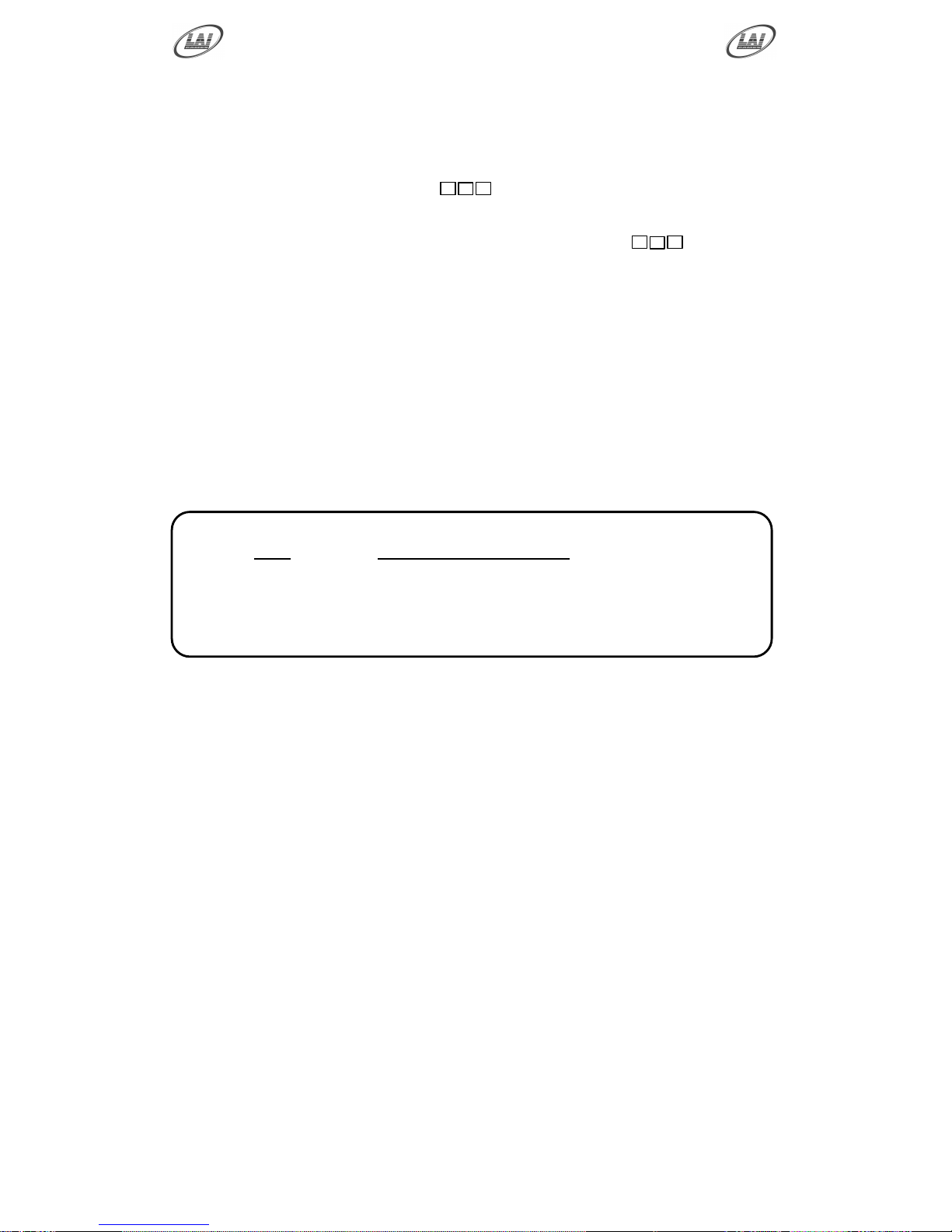
The number of ticket paid
for each game will be shown
on the 7-segment Displays
0 1 H H H H 1 0 H1 8 1 2
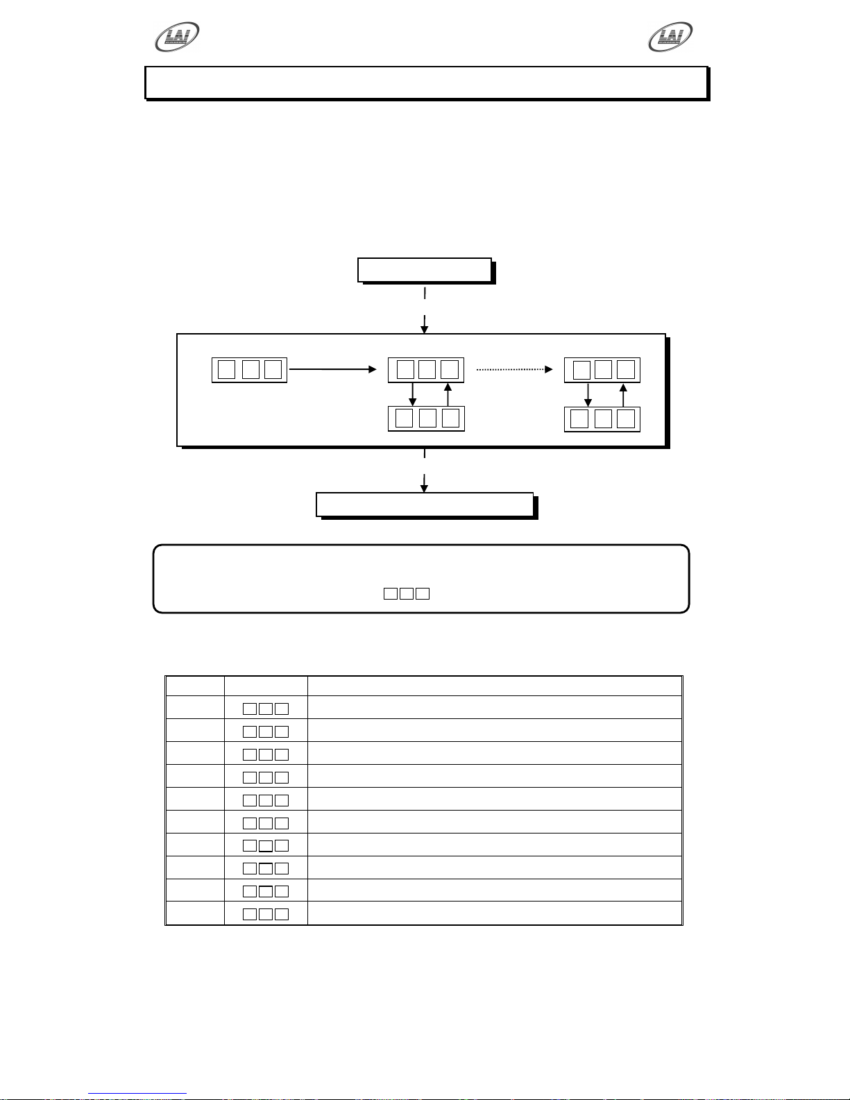
GAME HISTORY MODE
By using the Game History Mode the operator can view the results of the last 5 games
played. This enables the operator to verify tickets paid for a win / lose.
Example: The history results for the last Game Played. H01 shows the number of
tickets the Yellow Player received in the last game.
GAME HISTORY MODE DIAGRAM
GAME HISTORY QUICK REFERENCE TABLE
CODE
DISPLAY
HISTORY RESULTS
H01
H 0 1
Tickets Paid to Yellow Player Last Game Played
H02
H 0 2
Tickets Paid to Blue Player Last Game Played
H03
H 0 3
Tickets Paid to Yellow Player 2nd Last Game Played
H04
H 0 4
Tickets Paid to Blue Player 2nd Last Game Played
H05
H 0 5
Tickets Paid to Yellow Player 3rd Last Game Played
H06
H 0 6
Tickets Paid to Blue Player 3rd Last Game Played
H07
H 0 7
Tickets Paid to Yellow Player 4th Last Game Played
H08
H 0 8
Tickets Paid to Blue Player 4th Last Game Played
H09
H 0 9
Tickets Paid to Yellow Player 5th Last Game Played
H10
H 1 0
Tickets Paid to Blue Player 5th Last Game Played
PRESS TEST
GAME HISTORY MODE
PRESS
SERVICE
PRESS
SERVICE
To step from
H01 to H10
GAME ATTRACT MODE
PRESS TEST
* NOTE! *
Score Histories will be erased if the game is switched off then on.
Empty score histories show as
- - -
on the 3-digit display
AUDIT MODE
Loops back to H01
Tickets Paid
Page 30

Operator's Manual – FireFighter
© LAI GAMES
Page 25
GAME HISTORY PROCEDURE
ENTER The Game History mode is entered from Audits mode by pressing the
Test button once or from Attract mode by pressing the Test button six
times.
H H H
will be displayed on the 3-digit display.
SELECT The green Service button is pressed for advancing each step through
the set of Game Histories, starting from the
H H H
display, H01 being
the first step, continuing through to H10, and then looping again from
H01 to H10 until the mode is exited.
EXIT The Game History mode is exited into Game Attract mode, by pressing
the Test button once.
Page 31
Operator's Manual – FireFighter
© LAI GAMES
Page 26
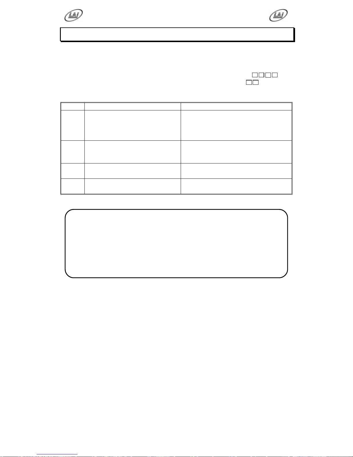
ERRORS AND TROUBLESHOOTING
If the Game microprocessor detects any problems with the operation of the game, an
Error will be displayed on the 3-digit display and the machine will play a voice
message. “Please Call the Attendant”. Some error Messages will only be displayed
when test mode is entered. Errors are displayed on the Timer display as
E r r
X
and
the error number in ether the Yellow or Blue player score display as
X
. where „X‟
is the error number, listed as follows:
CODE
ERROR DESCRIPTION
SOLUTION
Err1
TICKET DISPENSE ERROR
Jammed tickets, no tickets or no
ticket notch pulse for longer than
3 seconds.
Check if the ticket dispenser is jam or
empty of tickets. After clearing
dispenser jam or replenish tickets, push
Test button once to clear error.
Err3
EEPROM ERROR
Problem with on-board
EEPROM
The main MCU is getting errors reading
the EEPROM (24C16 IC on MCU).
Err4
TARGET SENSOR JAMMED
Check Target movement is free & test
sensor using switch test.
Err5
COIN SWITCH ERROR
Check switch movement & test coin
switches using switch test.
* NOTE! *
Error numbers displayed in the Yellow Player Score display indicate
the error has occurred on the Yellow Player side
Error numbers displayed in the Blue Player Score indicate the error has
occurred on the Blue Player side
The exception is Err3, this is displayed on the Yellow Player Score
display only.
Page 32

Operator's Manual – FireFighter
© LAI GAMES
Page 27
Err1 – TICKET ERROR
This error usually occurs if the game has run out of tickets or there is a
ticket jam. A less common reason is if the game PCB tries to dispense
tickets but doesn‟t get a notch pulse for approximately three seconds. You
can test the notch pulse by passing a ticket in and out of the notch sensor.
(See Switch Test, page 11).
If the game was out of tickets or jammed, replace the tickets, clear the
ticket jam and then push the test button once to clear the error. The game
will then payout any owed tickets.
Err3 – EEPROM ERROR
This Error is only displayed in test mode and means that the CPU cannot
read the EEPROM, or is receiving errors during communication with the
EEPROM (The 24C16 IC on the main MCU PCB). This could cause
problems with the game audits and program settings. The first thing to do
is trying to switch ON and OFF the machine in at least 2 cycles, if message
still appear than replace the EEPROM IC Atmel 24C16 on the CPU PCB
with the new EEPROM, If still Error massage, this could be a problems
with the game audits and program. If this error occurs, send your main
MCU PCB to the nearest authorized LAI games dealer for repair.
Err4 – TARGET SENSOR JAM
This error occurs if one or more of the target sensors are continuously
active. The target sensors are located behind the Fire hydrant on the
playfield, and are accessed through the lower back door. The magnets that
activate these sensors are located on the actual targets in the playfield.
This error can be caused by the target(s) being jammed and not swinging
freely. Clean the targets are make sure they are swinging properly and test
the sensors in the switch test mode (See page 11) and the run test mode
(See page 13).
This error can also be caused by the target sensor(s) being installed too
close to the magnet(s) on the target. Make sure that the sensors are far
enough from the target magnets that the sensor(s) are not active when the
target is in it rest position (Use Switch Test, page 11).
Err5 – COIN SWITCH ACTIVE ERROR
This Error is displayed when a coin input has been active continually for 5
seconds or longer. The problem is likely due to a stuck coin switch or
someone trying to „string‟ a coin.
This error can also be caused by connecting the Coin Input wire to the
Normal Closed (NC) connection on the coin switch.
Enter switch test mode (See page 11) to check with coin switch is active
and check the micro-switch on the appropriate coin mechanisms.
Page 33
Operator's Manual – FireFighter
© LAI GAMES
Page 28
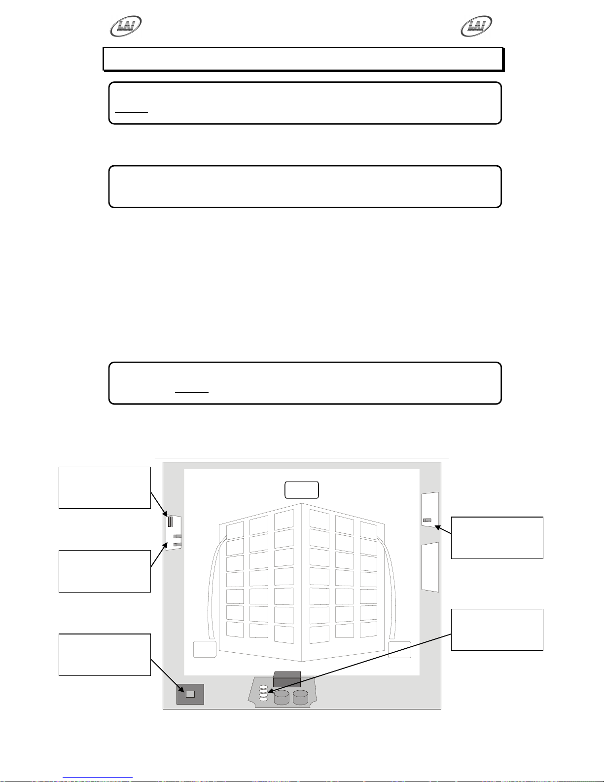
FUSE INFORMATION
MAIN AC SUPPLY FUSE (1 x 6 AMP FAST BLOW, M205 TYPE)
This fuse is for the main AC supply and is situated in the IEC mains input socket.
MCU POWER FUSE (1 x 1.5 AMP FAST BLOW, M205 TYPE)
This fuse is for the power supply to the MCU PCB.
MCU CONTROL FUSES (2 x 5 AMP FAST BLOW, M205 TYPE)
These fuses are for the DC transistor drivers on the MCU PCB
AC DRIVER FUSES (10 AMP FAST BLOW, M205 TYPE)
This fuse is for the 24VAC Lamps from the 8-Channel AC Driver PCB
24VAC TRANSFORMER (4 x 10 AMP FAST BLOW, 3AG TYPE)
This fuse is for the 24VAC Lamps from the 32-Channel AC Driver PCB
FUSE LOCATION DIAGRAM
As viewed from rear
* WARNING! *
Always turn OFF Mains power and unplugged the game, before replacing any fuses.
* NOTE! *
The power cord must be removed before the fuse can be accessed.
* CAUTION! *
Do Not use any fuse that does not meet the specified rating.
MCU Control
Fuses
5A QB M205
8 Channel AC
Controller Fuse
10A QB M205
MCU Power
Fuse
1.5A QB M205
24VAC
Transformer Fuses
10A QB 3AG
Main AC Supply
Fuse
6A QB M205
Page 34
Operator's Manual – FireFighter
© LAI GAMES
Page 29
SECTION A: SERVICE INSTRUCTIONS
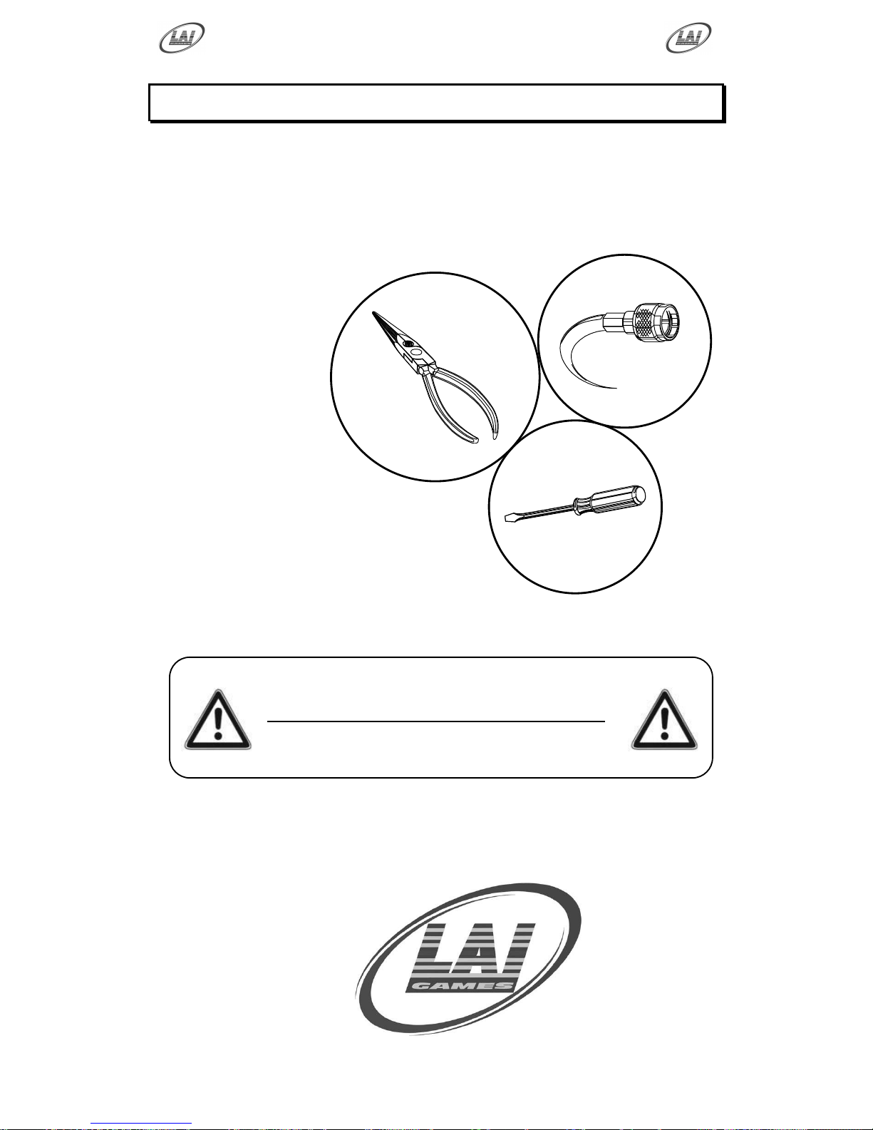
BE SURE TO READ THE FOLLOWING
Carefully before servicing this machine
A
Page 35
Operator's Manual – FireFighter
© LAI GAMES
Page 30
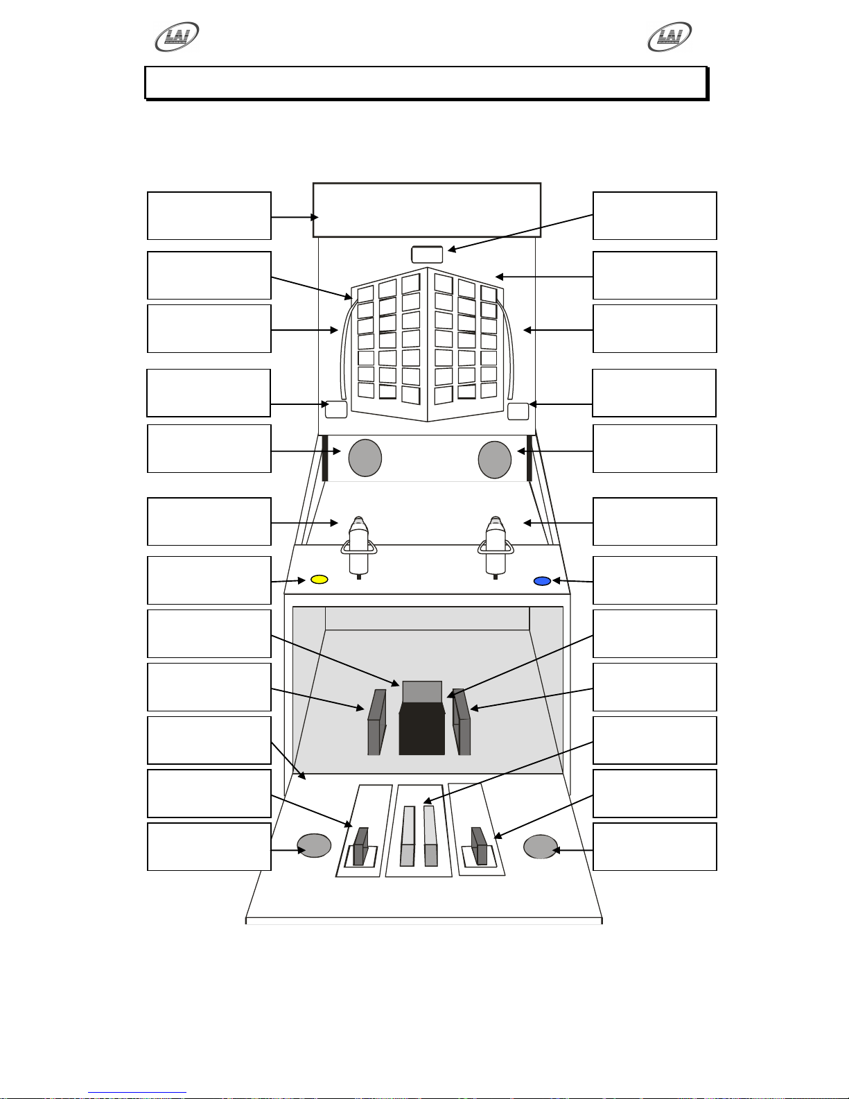
LOCATING AND ACCESSING PARTS
PARTS LOCATION DIAGRAM
As viewed from front
Acrylic Header
(Mylar)
Yellow Player
Score Display
Three Digit
Time Display
Blue Player
Score Display
Yellow Player
Level Display
Blue Player
Level Display
Yellow Player
Hose Lamps
Blue Player
Hose Lamps
Yellow Player
Hydrant Targets
Blue Player
Hydrant Targets
Yellow Player
Water Cannon
Blue Player
Water Cannon
Yellow Player
Start Button
Blue Player
Start Button
Service
Bracket
Cash Box
& Housing
Yellow Player
Ticket Holder
Blue Player
Ticket Holder
Front Drop
Door Panel
Coin
Mechanisms
Yellow Player
Ticket Mechanism
Blue Player
Ticket Mechanism
Speaker
Left
Speaker
Right
Page 36
Operator's Manual – FireFighter
© LAI GAMES
Page 31
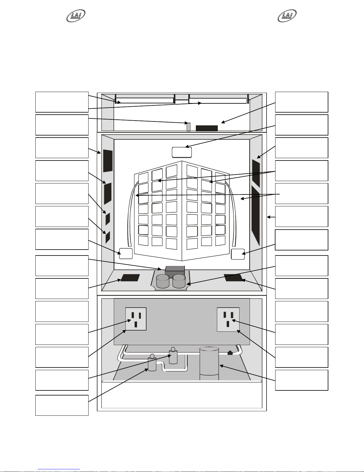
LOCATING AND ACCESSING PARTS
PARTS LOCATION DIAGRAM B
As viewed from rear
Fluorescent
Lamps
Fluorescent
Ballasts
Fluorescent
Starters
3-Digit
Display PCB
Game MPU
PCB
8 Channel AC
Driver PCB
Game Sound
PCB
24VAC
Level Lamps
Sound AMP
PCB
12V DC
Hose Lamps
DC SSR
Relay PCB
32 Channel AC
Controller PCB
12VDC
Power Supply
2x 12VAC
Transformers
Target GI
Fluoro. Lamp
Target GI
Fluoro. Lamp
Power Inlet
(On back panel)
Cooling Fans
(On back panel)
Blue Target
Reed Switches
Yellow Target
Reed Switches
Blue Target
Lamps
Yellow Target
Lamps
Player2 12VDC
Water Pumps
Water Filter
Assembly
2-Digit
Display PCBs
2-Digit
Display PCBs
Player1 12VDC
Water Pumps
Page 37
Operator's Manual – FireFighter
© LAI GAMES
Page 32
PARTS DESCRIPTION
COIN MECHANISMS
The coin mechanisms can be accessed inside the front center door in the center of
the machine cabinet.
CASH BOX
The cash box is located inside the coin door on the front of the machine cabinet.
TICKET MECHANISMS
Two ticket mechanisms can be accessed inside the front doors in the center of the
machine cabinet, one for each player
TICKET HOLDERS
Two ticket holder are located each side of the cash box and can be accessed inside
the front door in the center of the machine cabinet
SPEAKERS
Two speakers are located on the front side of the cabinet. Access is from the front
of the machine.
GAME CONTROLS:
Located at the front of the machine cabinet.
YELLOW START BUTTON: The Yellow Player Start button is the large
yellow round illuminated button located left-hand side of the control panel. This
button is used to start a single player game and for test and program adjustments
BLUE START BUTTON: The Blue Player Start button is the large blue round
illuminated button located right-hand side of the control panel. This button is used
to start a single or multi player game.
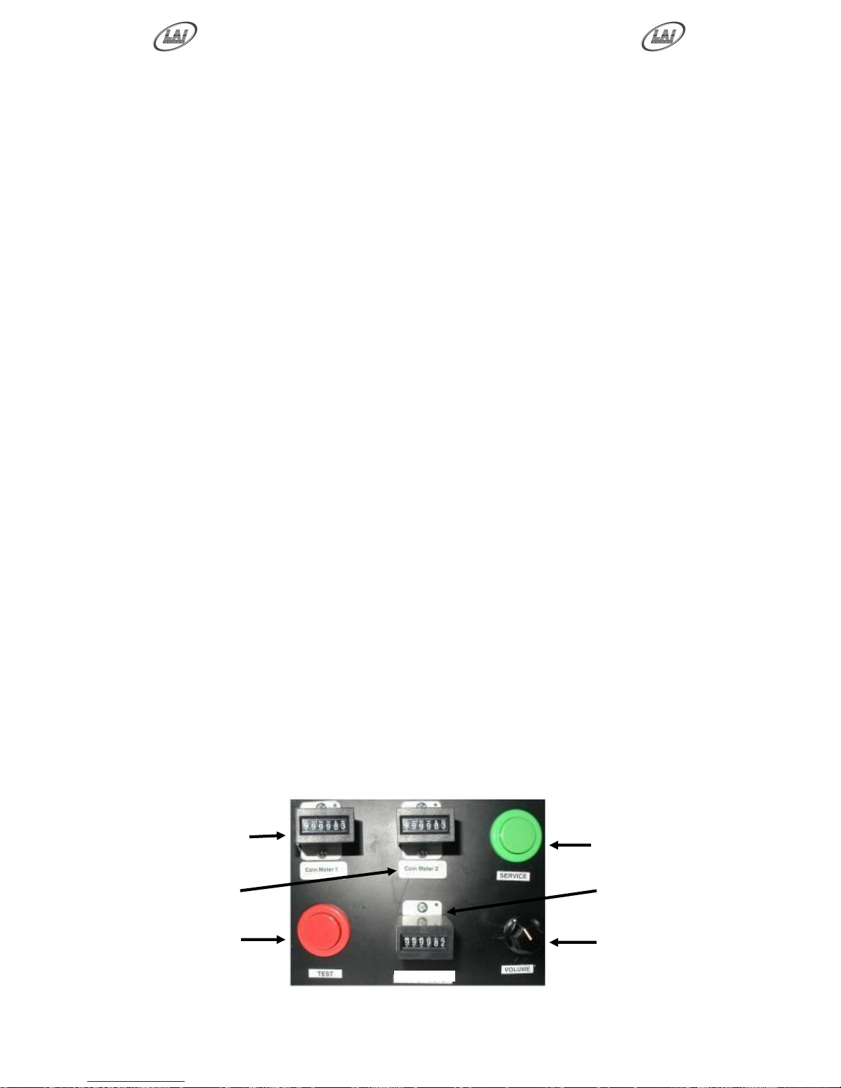
SERVICE CONTROLS:
Located on the service panel mounted on top of the cash box and accessed trough
the Coin Door.
SERVICE BUTTON: Used to input credits to the game without activating the
coin counter, and to perform test procedures in combination with the test button
TEST BUTTON: Used to perform the test mode, in combination with the
Service button.
VOLUME KNOB: Used to adjust the speaker‟s sound level.
SERVICE
BUTTON
VOLUME
KNOB
PRIZE
METER
COIN
METER 1
TEST
BUTTON
COIN
METER 2
PRIZE METER
Page 38
Operator's Manual – FireFighter
© LAI GAMES
Page 33
POWER CORD
The power cord is a standard IEC power cord (as used on computers) that is
plugged in to the power inlet socket at the rear of the machine. The power cord
can be removed for transport.
POWER INLET
The power inlet is located at the rear of the machine on the Left-hand side as
viewed from the rear. It is a standard IEC inlet socket.
MAINS SWITCH
The mains switch is located on the power inlet assembly along with the mains
fuse, and IEC inlet socket.
FUSES
For locations of all fuses refer to Fuses and Fuse location, page 28 of this manual.
PCB’s
For location of all game PCB‟s, refer to the Parts Location diagram page 30 of this
manual.
POWER SUPPLY
The power supply is located on the base of the upper cabinet and is accessed from
the rear of the machine. It is a 12V 13A switching power supply.
TRANSFORMERS
There are two transformers located on the base of the upper cabinet and is
accessed from the rear of the machine. They supply the 24VAC for the Level and
Target Lamps.
COOLING FANS
There is are two medium size cooling fans located on the bottom left and right rear
of the upper cabinet. Access is through the upper rear door at the back of the
machine.
TARGET REED SWITCH
The target reed switches are located in the rear of the lower cabinet. They are
activated by magnets mounted on the rear of the swinging targets. Access is
through the rear lower door.
WATER FILTER
The water filter is located to the left in the rear of the lower cabinet. Access is
through the rear lower door. The lower part of the filter is detachable for removal
and replacement of the filter cartridge.
PUMPS
Two 12VDC are located to the right in the rear of the lower cabinet, one for each
player water cannon. Access is through the rear lower door.
* WARNING! *
Always turn OFF Mains power and unplugged the game, before replacing any
fuses
Always use the correct rated fuse. Refer to page 28 for fuse information.
Page 39
Operator's Manual – FireFighter
© LAI GAMES
Page 34
LAMPS
HEADER LAMPS
There is two standard FL 15 fluorescent tubes for the Header Display. Access is
by the removing of the machine header cover and accessing the tubes from the
front.
TARGET ILLUMINATION LAMPS:
There is two electronic “Energy Saver” 9 watt fluorescent lamps for illuminating
the target area and are accessed from the rear upper door.
LEVEL DISPLAY LAMPS
There are 84 x 24V 5/8W GE301/303 lamps mounted at back of display. These
are standard 24/28 volt truck / aircraft lamps and are accessed from the rear upper
door.
HOSE DISPLAY LAMPS
There are 12 x 24V 5/8W GE301/303 lamps mounted at back of display. These
are standard 24/28 volt truck / aircraft lamps and are accessed from the rear upper
door.
TARGET LAMPS:
There are 6 x 24V 5/8W GE301/303 lamps mounted at back of each hydrant
target. These are standard 24/28 volt truck / aircraft lamps and are accessed from
the rear lower door of the machine.
COIN DOOR LAMPS
The coin door lamps all are 12V/DC GE194 or equivalent and can be accessed
through the coin door.
BUTTON LAMPS
The button lamps all are 12V/DC GE194 or equivalent and can be accessed
through the coin door or back door.
* WARNING! *
Always turn OFF Mains power and unplugged the game, before replacing any
lamps.
Always allow time for cooling as Lamps that have been active for a time may still
be too hot to touch.
* CAUTION! *
Always replace the lamps with the same or equivalent size, wattage and voltage.
* CAUTION! *
The Target Illumination lamps must be electronic compact fluorescent type. The
use of Incandescent type lamps will cause heat damage to the machine.
Page 40
Operator's Manual – FireFighter
© LAI GAMES
Page 35
MAINTENANCE
CLEANING AND CHECK UP
EXTERIOR
Regularly dust and clean the external cabinet areas as required, using a soft
water-damp cloth and mild soap. Check for blown bulbs and replace as required.
Any scratches or marks in the fiberglass or acrylic can be buffed out using car
polish or cut and polish.
INTERIOR
Regularly dust and vacuum the interior of the cabinet, taking care to remove any
objects that may have fallen on the PCBs. Check and tighten all fixing hardware
and fasteners as required.
Regularly check that all the Display and Button Lamps are operating through the
Sounds, Lamps and Display Test (See page 11). Replace any globes that are not
operational.
Regularly check that the two cooling fans are clear of dirt buildup and are
operational. Clean air-flow of any dirt or obstruction and oil or replace any fan
that is not operational.
WATER SYSTEM
Regularly enter Run Test Mode and run both pumps together to check the Water
Cannon pressure is sufficient for activating the Targets, adjust as needed.
Regularly empty the water from the machine and replace with fresh water. Refer
to page 6 for empting and filling of the machine.
Regularly check the filter cartridge is not clogged and change if necessary. The
symptoms of clogged filter are insufficient pump pressure to operate two players
at the same time.
* CAUTION! *
Do not use solvents on the panels as it may affect the artwork.
* WARNING! *
Always turn OFF Mains power and unplugged the game, before cleaning the
interior of the machine.
Always after cleaning the cabinet interior, check all harness connectors and
restore all loose or interrupted connections.
* CAUTION! *
Always replace any non operational fans. This will prevent overheating of the
upper cabinet and prolong the life of the electronic components and lamps.
Page 41
Operator's Manual – FireFighter
© LAI GAMES
Page 36
SECTION B: TECHNICAL DETAILS
It is advised that anybody using SECTION B for
repairing or modifying any of the components of the
game should be a qualified technician, having at least
a basic knowledge of digital components, integrated
circuits and electricity.
B
Page 42
Operator's Manual – FireFighter
© LAI GAMES
Page 37
MAINS VOLTAGE ADJUSTMENT
POWER SUPPLY
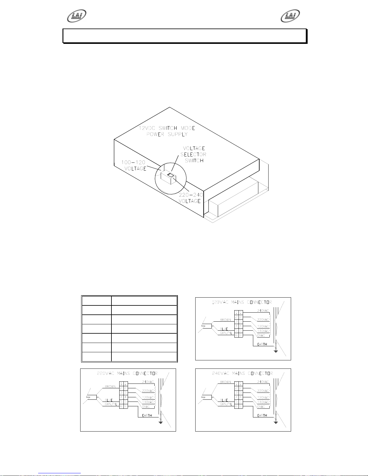
The Switch Mode Power Supply has a switch to set the mains voltage range. It is
located at the rear of the game cabinet, and is accessed via the back door. Use a
thin blade screwdriver to move the selector switch to the desired mains voltage
(See Diagram Below)
TRANSFORMER CONNECTORS
Locate the machine transformer(s) in the base of the cabinet. If unsure of the
location of the transformer(s), refer to Parts location diagram on page 30 of this
manual. Change the position of the „ACTIVE‟ or „HOT WIRE‟ input, (marked
brown on the diagram), to the position for the desired mains voltage. (See
Diagram Below)
6 WAY CONNECTOR PINOUT
PIN
FUNCTION
1
240VAC
2
220VAC
3
120VAC
4
110VAC
5
0VAV (NEUTRAL)
6
EARTH
Page 43

Operator's Manual – FireFighter
© LAI GAMES
Page 38
FLORESCENT TUBE BALLASTS AND STARTERS
Locate the florescent tube ballasts and starters in the back of the cabinet. If unsure
of the location of any ballasts or starters, refer to Parts location diagram on page
30. These have to be removed and replaced with an equivalent wattage at you
local mains voltage level.
TARGET ILLUMINATION LAMPS
Locate the two “Energy Saver” 9 watt fluorescent Target Illumination lamps,
which are accessed from the rear of the machine, (see page 30). These have to be
removed and replaced with an equivalent wattage at you local mains voltage level.
COOLING FANS
Locate the two cooling fans, which are accessed from the rear of the machine, (see
page 30). These can to be removed and replaced with an equivalent size at you
local mains voltage level. Alternately, use the wiring as shown in the Power
Wiring Diagram (See Page 51) to “auto tap” the 220VAC required for the cooling
fans.
Page 44

Operator's Manual – FireFighter
© LAI GAMES
Page 39
TICKET DISPENSER REFERENCE GUIDE
The ENTD-2000 Ticket Dispenser has been designed with features that virtually
eliminate ticket jams. It requires very little maintenance, making it the most reliable
and compatible ticket dispenser on the market today. This guide is designed to explain
the basic functions and specifications of the ticket dispenser.
BASIC OPERATION
LOADING TICKETS
1. Select ticket width.
2. Slide ticket through guide plates until they reach the rollers.
3. Depress the auto advance button until the tickets reach the desired location.
4. If tickets do not load, ensure that the upper rollers are engaged by pulling
back on the latch bar.
TICKET STOP ADJUSTMENT
This function allows the length of the tickets protruding from the face plate to be
adjusted.
1. Turn the two Phillips pan headed screws on the PCB one quarter of a
revolution counter-clockwise.
2. Move the board forward or backward to the appropriate position.
3. Re-tighten the screws.
* NOTE! *
The upper rollers can be disengaged by pulling on the latch bar.
This is useful to clear tickets, etc.
Page 45
Operator's Manual – FireFighter
© LAI GAMES
Page 40
CLEARING TICKET JAMS
1. Gently pull any tickets that are between the rollers and front plate out the
front of the unit.
2. Lift the upper rollers by pulling the latch bar back into the unlock position.
3. Unlatch the upper ticket guide by raising it off its post in the back.
4. Push the tickets away from the ticket width selector toward the optic switch.
Gently pull the tickets toward the rear of the unit.
5. Tear off the damaged tickets and put the upper ticket guide back into place.
6. Reload tickets as previously discussed. (Be sure to place the latch bar back
to the locked position).
EASY RELEASE AND RE-INSTALL
1. Hold the dispenser unit and bend the retainer clip to remove it from the face
plate.
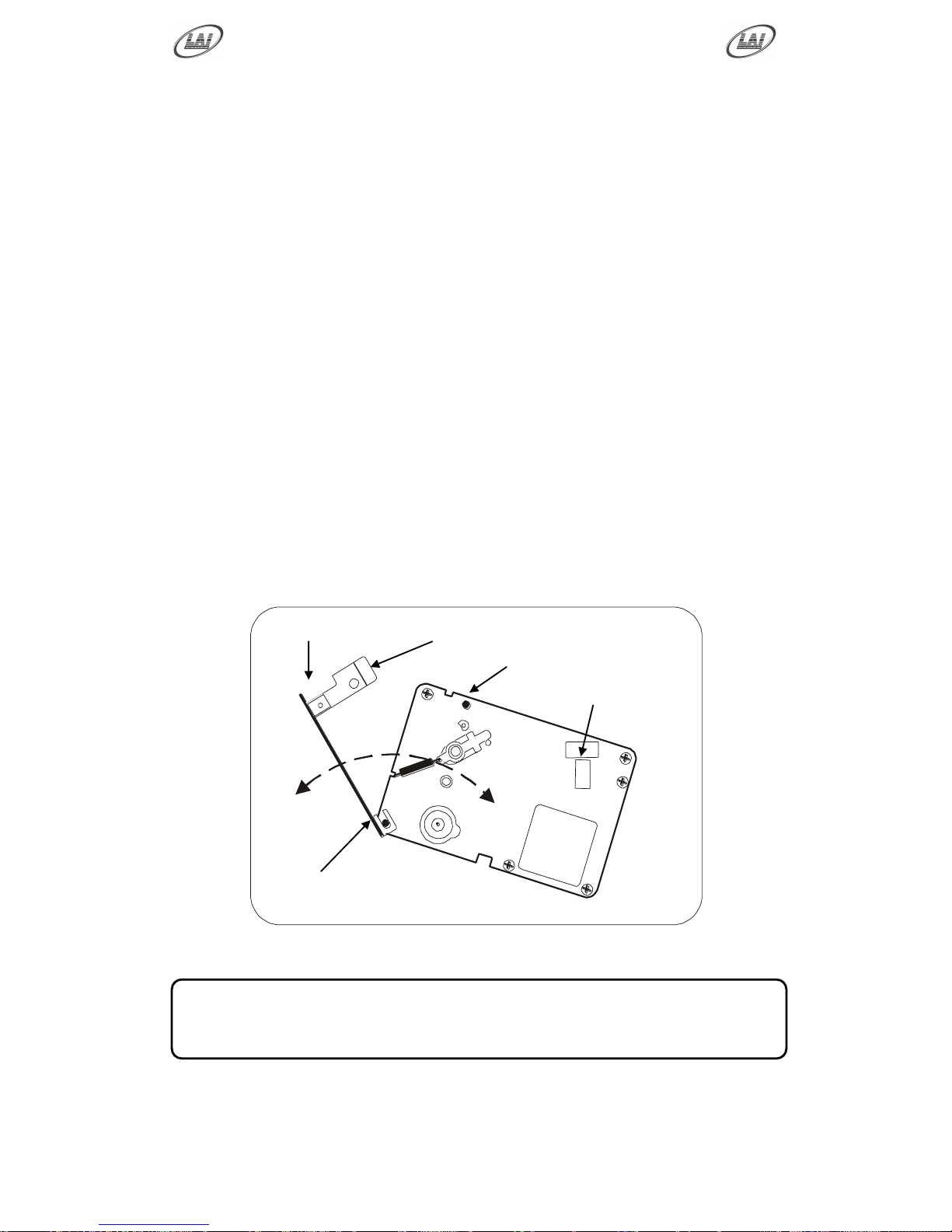
2. Swing the unit down then lift it slightly until the dispenser unit releases from
the face plate.
3. To reinstall: align the post on the dispenser unit w/the U shape brackets on
the face plate.
4. Swing unit up and snap in place
Bottom Shaft
Face Plate
Retaining Clip
Clamping Post
Width Selector
* NOTE! *
Ensure the dispenser is firmly locked in place before running it again!
Page 46

Operator's Manual – FireFighter
© LAI GAMES
Page 41
SPECIFICATIONS
LED FUNCTION
GREEN LED: Notch output indicator.
YELLOW LED: Motor Enable.
STANDARD TICKET UNIT: TD-963CR
The TD-963CR is designed to fit more applications. The game‟s software turns
the dispenser on with a logic high signal and monitors a return notch signal from
dispenser to turn it off.
OUT PULSE TICKET UNIT: TD-963PR
The TD-963PR is designed for one logic input - one ticket game. The game
pulses the dispenser once and one ticket is dispensed.
OUT PULSE TICKET UNIT: TD-963PR
The Td-963sr uses a switch rather than a logic input. The game must ensure the
switch will not be activated more than twice per second.
ELECTRICAL CHARACTERISTICS
TD-963CR:
Min. Typical Max.
Supply Voltage 11.0 V 12.0 V 13.0V
Standby Current -------- 25mA -------Motor Start Current 1.2 A 1.3 A 1.4 A
Motor Run Current 0.3 A 0.3 A 0.35 A
Motor Enable On Voltage 2.4 V -------- 12.0 V
Motor Enable On Current 160 uA -------- 4.2 mA
Motor Enable Off Voltage -------- -------- 1.0 V
Motor Enable Off Current -------- -------- 0 A
Ticket Notch Sink Current -------- -------- 50 mA
Ticket Notch Voltage Pull-up -------- -------- 30 V
Page 47
Operator's Manual – FireFighter
© LAI GAMES
Page 42
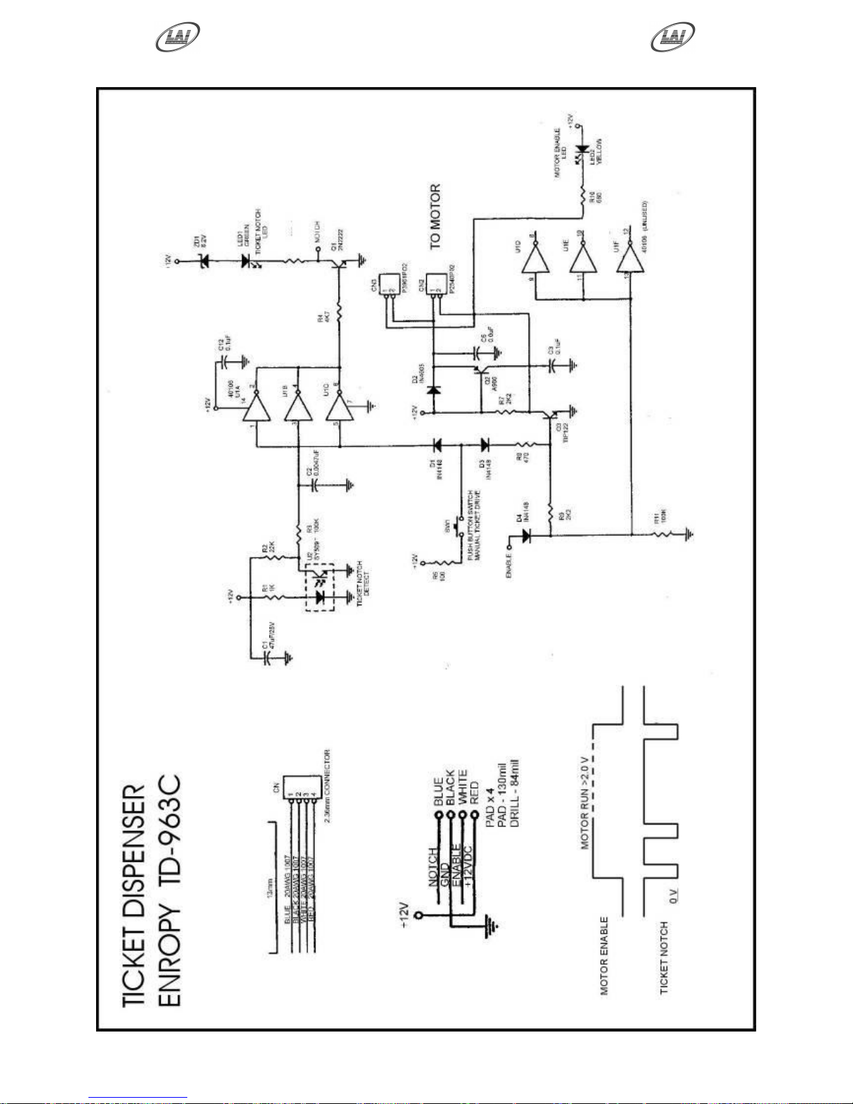
TD-963CR SCHEMATIC DIAGRAM
Page 48
Operator's Manual – FireFighter
© LAI GAMES
Page 43
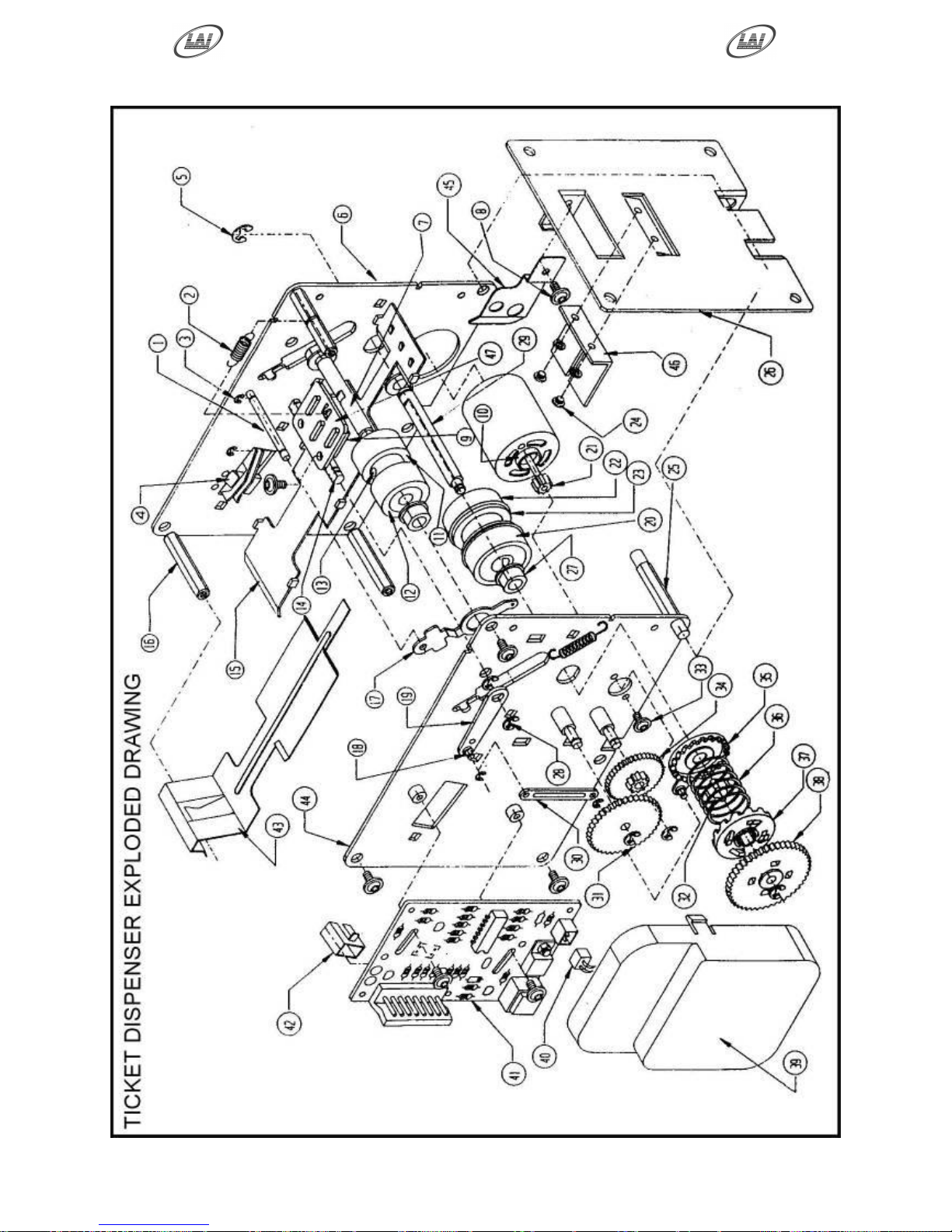
DISPENSER PARTS DIAGRAM
Diagram is for reference only.
Parts are not available
separately
Page 49
Operator's Manual – FireFighter
© LAI GAMES
Page 44
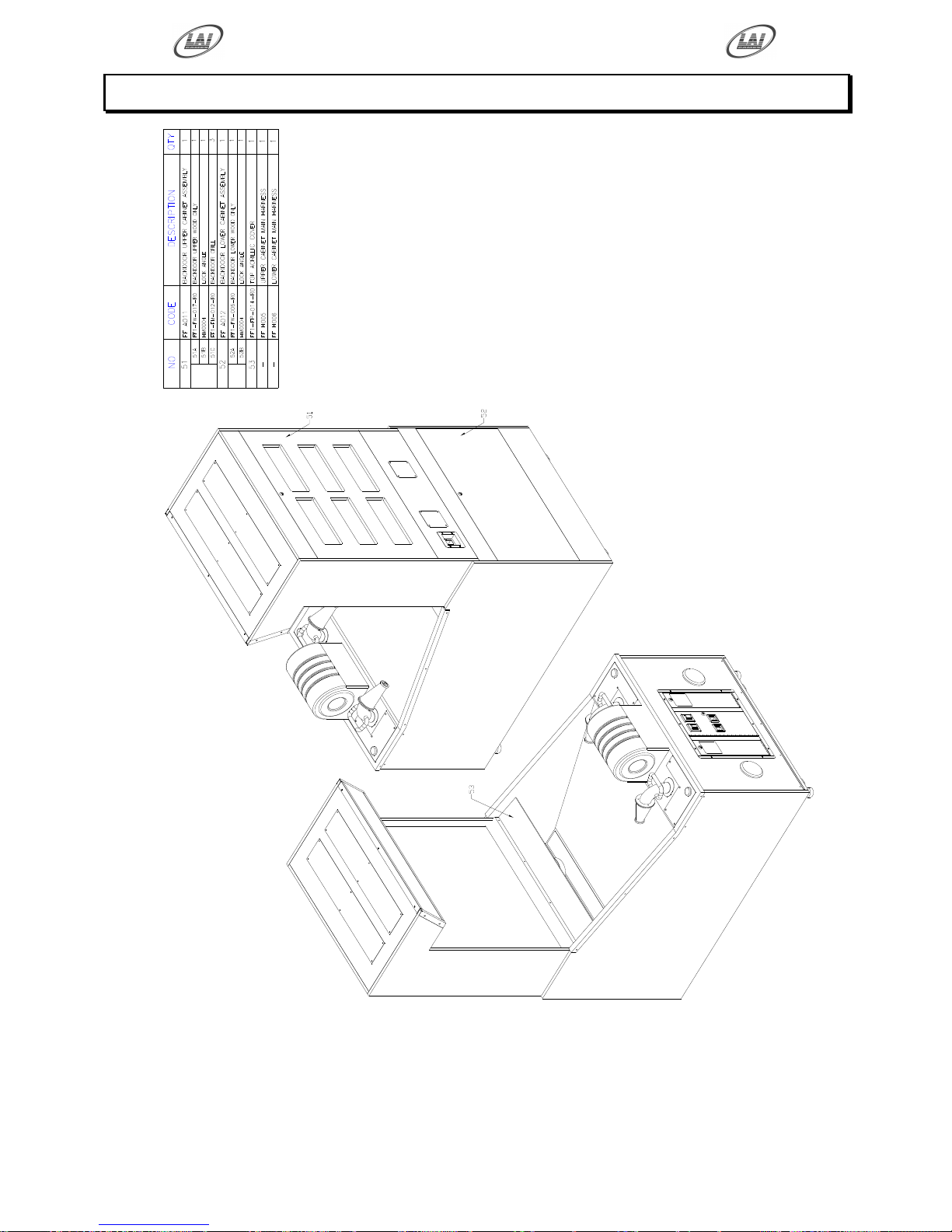
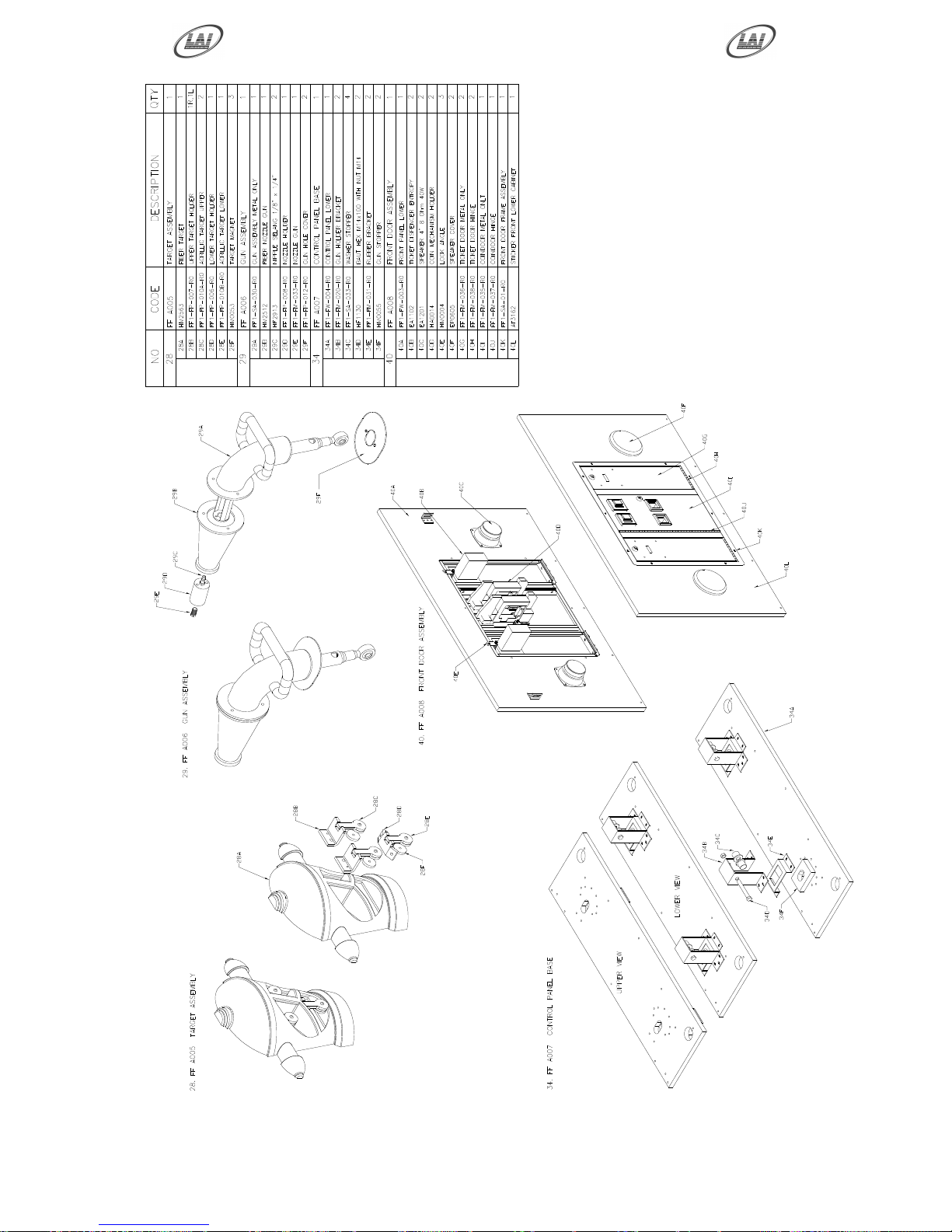
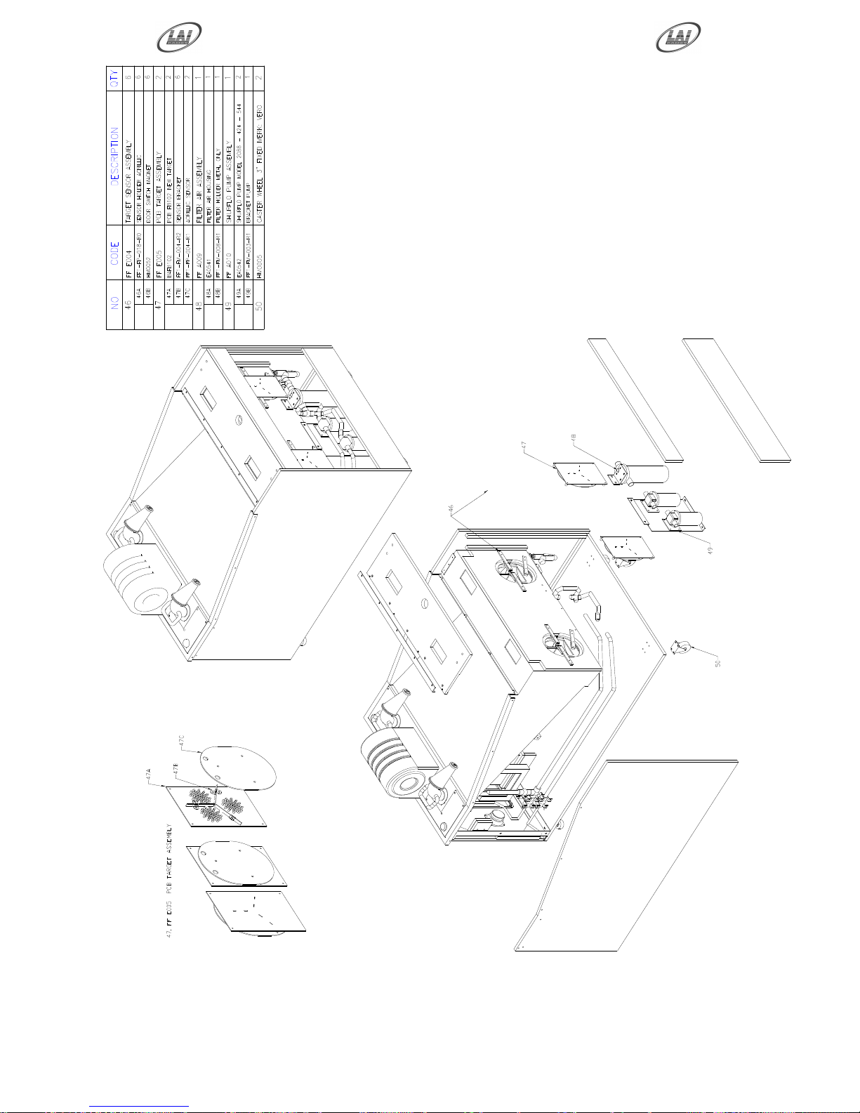
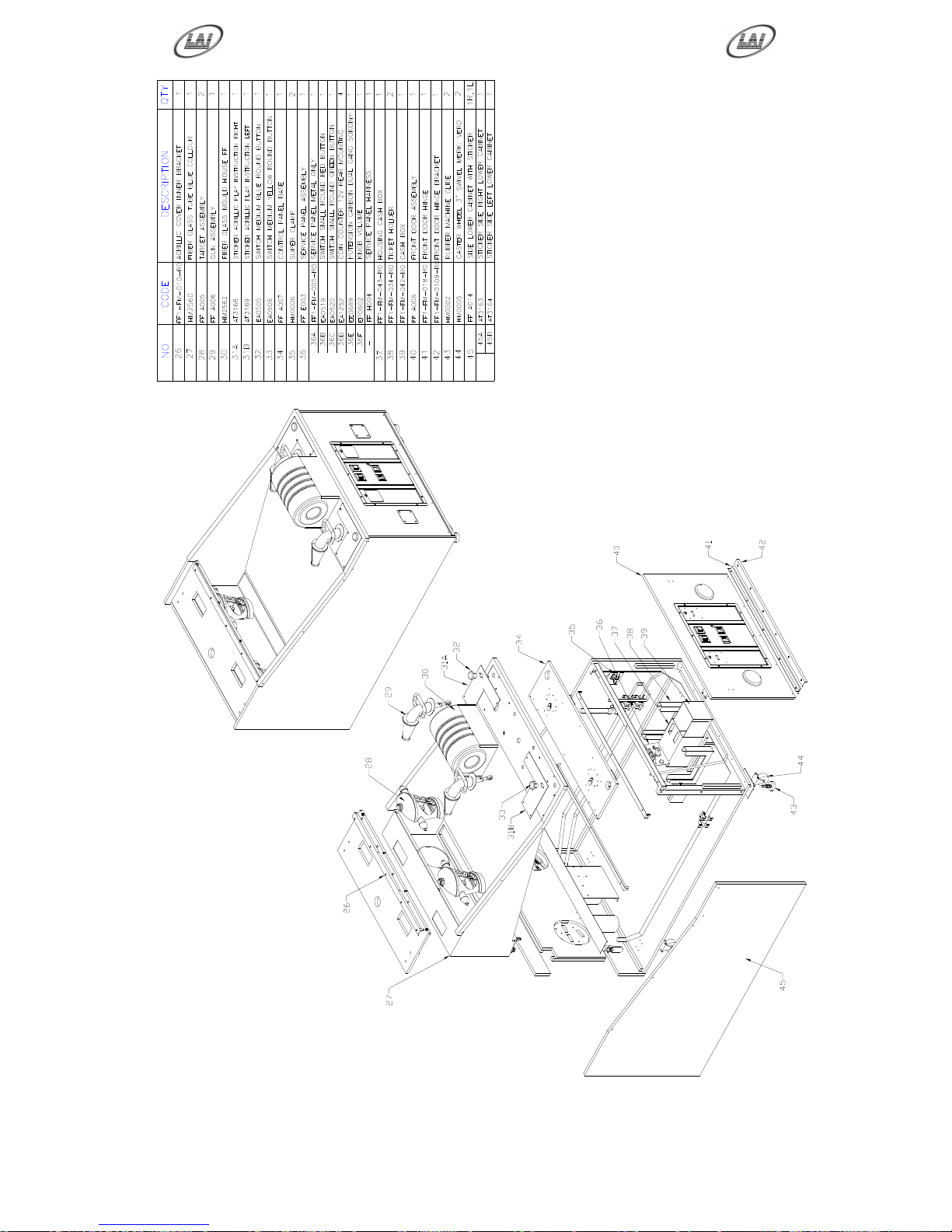
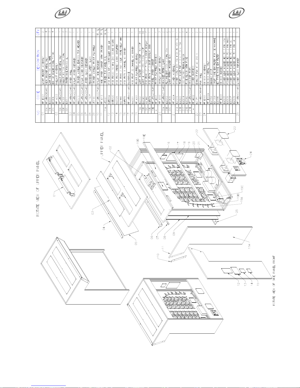
3 D EXPLODE PARTS
Page 50
Operator's Manual – FireFighter
© LAI GAMES
Page 45
Page 51
Operator's Manual – FireFighter
© LAI GAMES
Page 46
Page 52
Operator's Manual – FireFighter
© LAI GAMES
Page 47
Page 53
Operator's Manual – FireFighter
© LAI GAMES
Page 48
Page 54
Operator's Manual – FireFighter
© LAI GAMES
Page 49
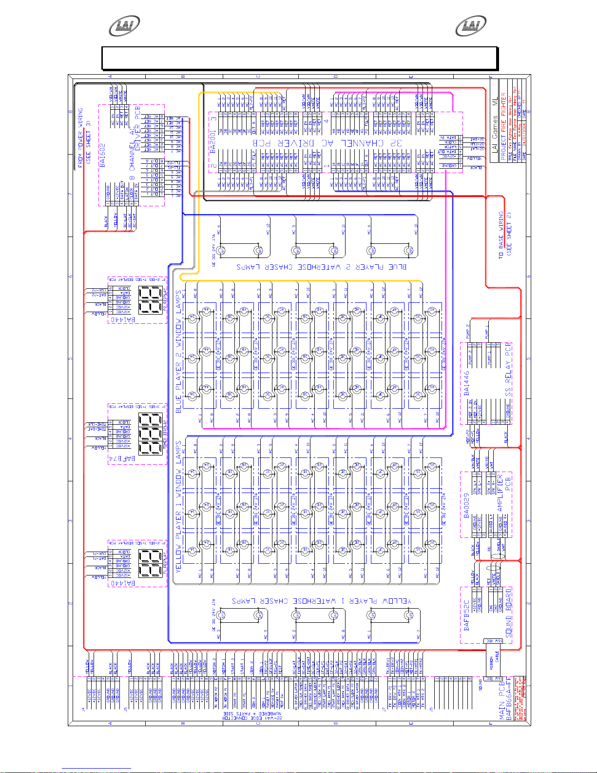
FIREFIGHTER MAIN WIRING DIAGRAM
Page 55
Operator's Manual – FireFighter
© LAI GAMES
Page 50
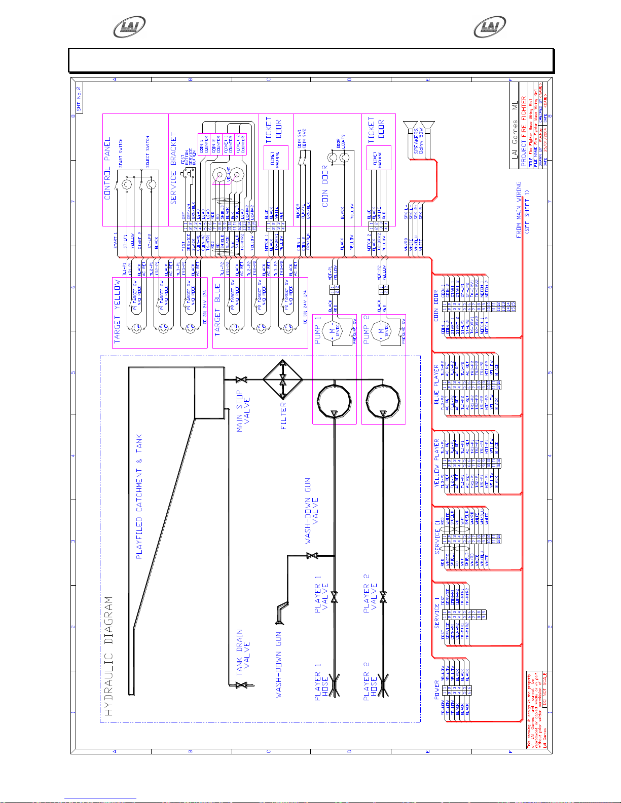
FIREFIGHTER BASE WIRING DIAGRAM
Page 56
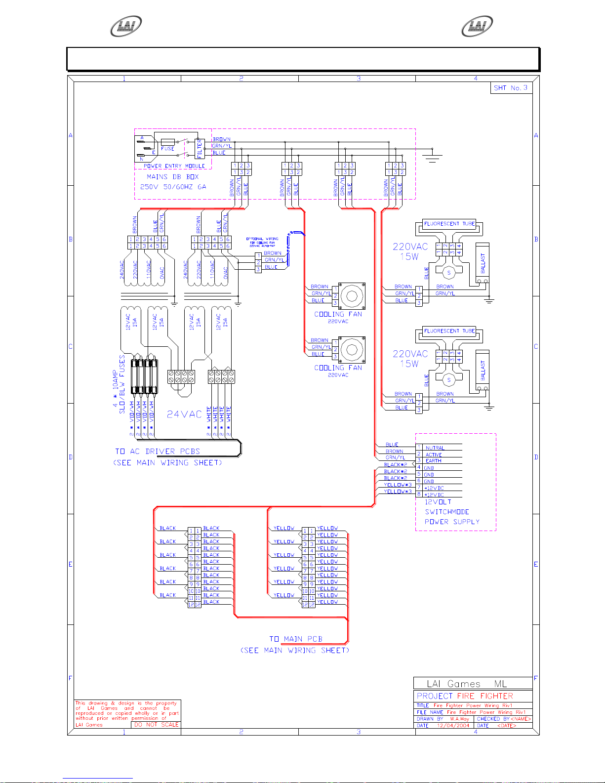
Operator's Manual – FireFighter
© LAI GAMES
Page 51
FIREFIGHTER POWER WIRING DIAGRAM
Page 57
WARRANTY
LAI GAMES warrants its manufactured products for a period of 3 months inclusive
of parts and labor from the date of sale.
LAI GAMES exclusive obligation is to repair any item with any defects as a result of
faulty workmanship or materials, providing the defective item or items of equipment
are returned to the LAI GAMES distributor from which the machine was purchased.
LAI GAMES shall have no obligation to make repairs necessitated by negligence or
interference to any component by any unauthorized personal. This will automatically
void any existing warranty.
IF MAKING A WARRANTY CLAIM:
(a) A Copy of the sales invoice must accompany the claim.
(b) To and from Transport and freight costs are not covered by the
warranty.
(c) Warranty is not transferable with the sale of a machine from one
owner to another.
LAI GAMES
Page 58

INTERNATIONAL SALES & SERVICE
For your nearest LAI GAMES Distributor
visit our web site at
http://www.laigames.com
 Loading...