

Laguna Tools SmartShop MCNC-LTL-CO2-MU-2012-40, SmartShop MCNC-LTL-CO2-MU-2420-40, SmartShop MCNC-LTL-CO2-MU-2420-80 User Manual

SmartShop Laser | MU
MCNC-LTL-CO2-MU-2012-40
ltl-CO2-MU-2420-40
ltl-CO2-MU-2420-80
LAGUNA TOOLS
17101 Murphy Ave.
Irvine, California 92614
Ph: 800.234.1976
www.lagunatools.com
Model Numbers MCNC-LTL-CO2-MU-2012-40
ltl-CO2-MU-2420-40
ltl-CO2-MU-2420-80
© 2017, Laguna Tools, Inc. LAGUNA® and the LAGUNA Logo® are the registered trademarks of Laguna Tools, Inc. All rights reserved.

Directory
2.2 Equipment Composition............................................................................................ 7
2.2.1 Equipment Composition................................................................................. 8
2.2.2 Transmission System......................................................................................... 9
2.2.3 Optical System................................................................................................. 10
2.2.4 Control System.................................................................................................11
2.2.5 Peripheral equipment....................................................................................... 12
2.3 Front of the Machine...................................................................................................15
3.Equipment Installation........................................................................................................... 16
3.1Preparation before Installation.....................................................................................16
3.1.1 Site Preparation.............................................................................................16
3.1.2 Personnel Preparation................................................................................... 16
3.1.3 Tool Preparation............................................................................................16
3.1.4 Other Preparation.......................................................................................... 17
3.2 Installation procedure..........................................................................................................17
3.2.1 Package of Laser Tube.................................................................................................. 17
3.2.2 Installation of Laser Tube................................................................................ 17
3.2.3 Water Pump Installation...................................................................................18
3.2.4 Exhaust Fan Installation................................................................................20
3.2.5 Air Pump Installation....................................................................................20
3.3Ground Line Connection..............................................................................................21
4 Equipment Debugging........................................................................................................... 21
4.1Inspection before Debugging.......................................................................................22
4.1.1Boot Process..............................................................................................................22
Power On:..........................................................................................................................22
4.1.2 Test Running................................................................................................. 22
4.2 Laser Debugging.........................................................................................................22
4.2.1 Output of the Laser Tube................................................................................. 22
4.2.2 Laser Path Debugging......................................................................................23
4.2.3Test Processing..................................................................................................28
5. Simple operating instructions................................................................................................29
5.1 Simple operating instructions..................................................................................... 29
5.2Data line using operation............................................................................................. 31
5.2.1 Parameter Matching......................................................................................... 32
5.2.2 Make simple pictures&Set picture layers........................................................37
5.2.3 Set working mode......................................................................................... 39
5.2.4 Download files................................................................................................. 40
5.2.5 Equipment Operation............................................................................................... 41
5.3 U-disk Operation.................................................................................................................43
6. Rotary Processing..........................................................................................................................45
6.1 Electrical Installation.......................................................................................................... 45
6.1.1 Rotary Connection................................................................................................... 45

6.2 Software Operation............................................................................................................. 46
6.2.1 Software Setting.......................................................................................................47
6.2.2 Cutting Test.............................................................................................................. 50
7. Equipment maintenance and repair...............................................................................................54
8. CO2 Laser Tubes of Glass Usage Considerations................................................................ 56
Preface
Thank you for choosing our products. We will provide you with
comprehensive after-sales service and solutions, please keep this
instruction booklet and other attachments for your better use later.
This statement only applied to our standard equipment, for special
ordered Machine, please read the attached documentation.
The Manual is going to show you the work Principle, methods of
installation, operation, troubleshooting, transport and storage and

maintenance. If it’s your first time to use this product, please read this
information carefully before installation and use.
For quick and efficient using this equipment, the user should meet
conditions as below:
A. Operator requires a certain amount of computer expertise to edit the
graphics software ,For Example:
Coreldraw,Photoshop ,Autocad and other CAD software.
B. Operators have a certain knowledge of optics and electrical related
equipment repair and maintenance
C. Confirmed that the operator is familiar with the equipment operating
procedures before starting the and do as it’s instruction.
Apologized that due to the constantly product updated,maybe somewhere
is different with your products.
Brief Introduction of Laser Engraving Machine
1. Safety knowledge
1.1 Basic Information
● Make sure that the operator is trained before operating the machine.
● In order to avoid unnecessary loss,the operator is prohibited from
leaving and must observe the machine at all the times when it under
working.
1.2 Optical Security

Our Equipment Adopts the Fourth Laser that the wavelength is 10.6μm,
Recommended that the operator wear the accredited laser protective
glasses.
Even wear the laser protective glasses and do not look directly at the laser
beam or any reflection of the laser beam.
1.3 Electricity Security
Observe the machine nameplate carefully such as power and voltage
requirement before you access the power supply.
Without our permission,please do not disassemble the electrical parts
yourself .Especially do not touch the laser power supply ,laser tube when
it s working because of its lethal voltage,the danger still exists even
power outage.
1 Hazard
a wide variety of potentially dangerous substances that produced by the
plastic materials when processing can be removed by the ventilation
systems,if the smoke or the smell is too big ,the gas mask is needed.
2 Other hazards
For security purposes,Equipment modification is strictly prohibited
without the manufacturer agreement.
2. Equipment Brief Introduction
Equipment adopted the high-precision transmission shaft and servo-drive
can be realized fast and smooth carving.Non-Metal materials can be cut
or engraved by the high efficiency laser tube.
※※※一※※※※一※※
Machine Series :
BCL:
bodor cutting laser
BML:
bodor marking laser
Working area
:
0503:500mm×300mm
0605:600mm ×500mm
1006: 1000mm×600mm
1309: 1300mm×900mm
1610: 1600mm×1000mm
… ……
Model description
:
M: Mini Series
X: Standard Series
B :Laser Cutting Bed
FB:Fiber Laser Cutting Series
YB/YT:YAG Laser Cutting Series
FP:Fiber Marking Series
additional devices

1-1 Machine Model Description
Example:BCL1309XU means working area:1300mm×900m with up-down system.
2.1 Nameplate Introduction
The nameplate fixed on the right rear of the device which can get more
equipment information.No randomly change or demolition.

2.2 Equipment Composition
Machine Appearance or the some details are different because of the
model or Machine improvement.Specific to the material object as the
standard.
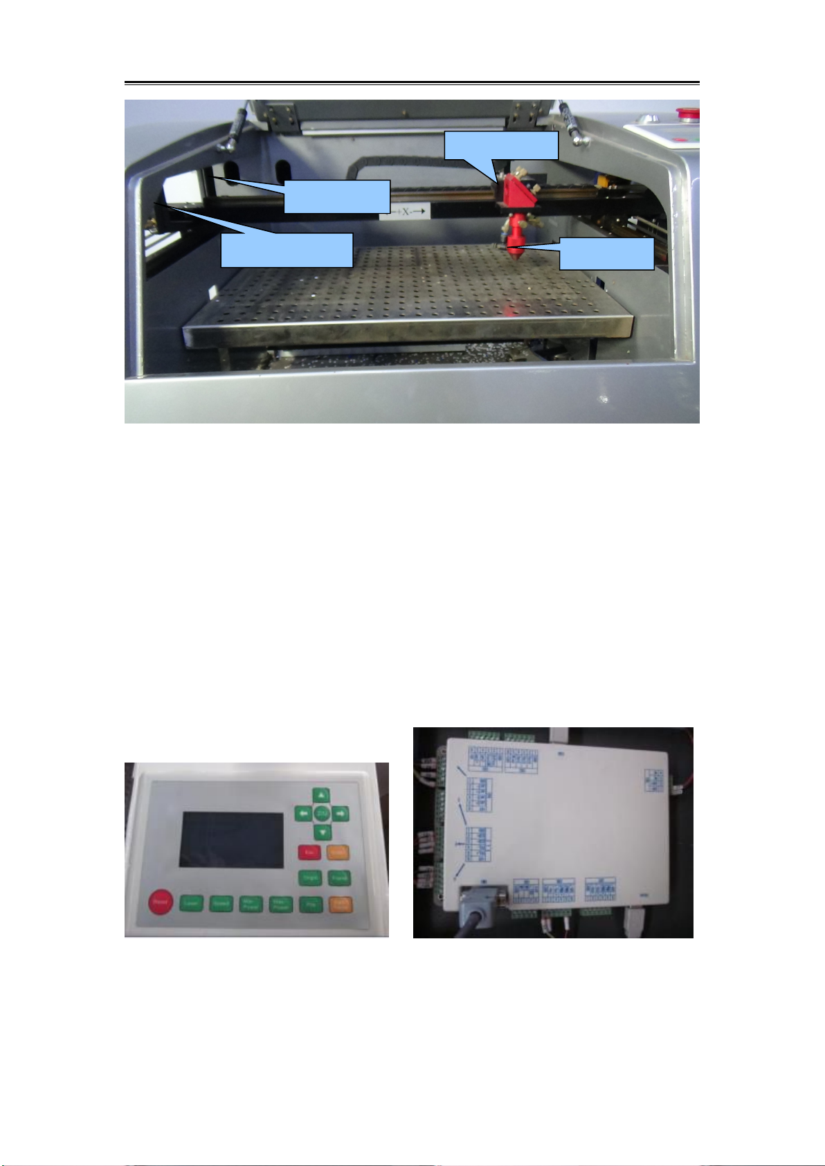
Liner Guide
Laser Head
Slider
Belt
Red Dot System
Nozzle Connector
Unique Equipment Number

2.2.1 Equipment Composition
Laser
Machine
Machine
Body
Transmis
sion
System
Optical
System
Control
System
Peripheral
equipment
Tool Box
1
2
3
4

Picture 1: Machine body:body、transom、upper shield,Up&Down table
1-Liner Guide 2-Laser head 3-Slider 4-Belts 5-Stainless Steel Working
Table 6-Photoelectric switch 7-Nozzle Connector 8-Red Dot System
2.2.2 Transmission System
8
5
6
7
Motor
Transom
Transmission Shaft

Picture 2: Transmission System is Composed of Motor ,Driver ,
Transmission Shaft,Liner Guide,Slider,Belt.
2.2.3 Optical System
Note: Laser tube must be handled with care during installation;High
Voltage and Cathode lines should be tense properly;Water inlet on the
upper and outlet on the below(Reci Tube);Ensure that no bubble inside
the tube;Evenly Strength on both sides when fix the laser tube on the
Basement.Make sure it Solid and not crushed.
Liner Guide
Belts
Slider
Belt
Picture 3:Optical System :Three Reflectors and Focal Lens Device
2.2.4 Control System
Control Systems are different because of the machine model,Specific to
the material object as the standard!
Our control systems as below :Leetro
、
Ruida
Ruida Control Panel Ruida Control Card
First Reflector
Second Reflector
Third Reflector
Focal Lens

Leetro Control Panel Leetro Control Card
Picture 4: Control System:Control pane, Control Car,Computer
Control Card
Power Supply
Laser Power Supply
Data Line
Driver
Relay

2.2.5 Peripheral equipment
Picture 5: Peripheral equipment:Water Pump,Exhaust Fan ,Air Pump
2.2.6 Tool Box
Exhaust Fan Socket
Water Pump
Air Pump
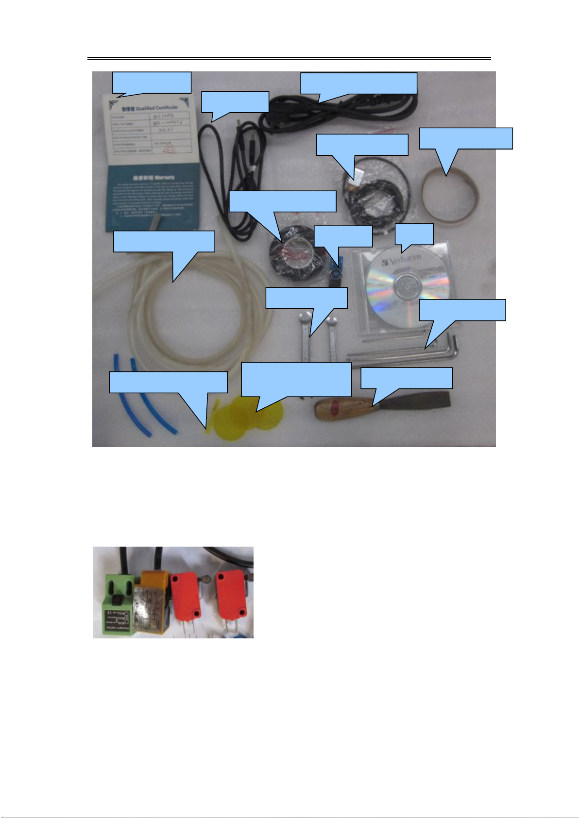
Picture 6 Tool Box
Note:Tool Box is different because of the machine model,Specific to the
material object as the standard.!
Limit switches :Proximity switches and Micro switches
Certification
Data line
Power Supply Line
Limit Switch
Adhesive Tape
High pressure tape
U Disk
CD
Water/Air Pump
Fork wrench
Laser Path
Allen wrench
Focus Distance Block
shovel blade

shovel blade Usage Focus Distance Block Usage
Picture 7 Shovel Blade Focus Distance Block
2.3 Front of the Machine
Picture 8:Control Panel
Focal Distance Block
On/Off button
Emergency Stop
Control Panel

Picture 9: Machine Power Supply Socket
3.Equipment Installation
3.1Preparation before Installation
3.1.1 Site Preparation
Equipment should be set in dry environment without electromagnetism
and high-strength electricity, without pollution's disturbance and effect.
Temperature of working environment is 10-38℃, humidity is 10-90%,
AC 220V±10%, 50HZ,resistance to ground should be smaller than 5Ώ.
3.1.2 Personnel Preparation
The operator must master the main point of installation. Otherwise, the
damage of machine parts will not in our scope of protection.
Three-hole Strip
Ground Line Connector
Fuse
Power Supply Connector
Water inlet
Water Outlet
Air Pump Connector

3.1.3 Tool Preparation
There is tool box with this machine. Besides, multimeter and screw driver
and other detection tools are needed.
3.1.4
Other Preparation
Purified water for water chiller, power strip, pipe for discharge smoke,
sample material, etc.
3.2 Installation procedure
3.2.1 Package of Laser Tube
In case of damage during transportation or outside force, the tube is
packed with sponge. And two ends of tube are sealed with zip lock bag to
prevent the mirror from pollution or scratch. Finally, the tube is built up
with sponge supports to prevent tube have direct contact with
surrounding.
3.2.1.2 Open the carton box, take out the laser tube. Both hands hold the
middle of the tube; take off the sponge supports; take off the packing
sponge; take off the zip lock bag. Then inspect whether the tube is intact.
If tube have any defect, please take photo and send to Bodor for
confirmation.
Attention: It needs as least two person when remove the package. Handle
the tube with care.
3.2.2 Installation of Laser Tube
Open the back cover. You can see two white laser basement, two water
pipes, and black color low-voltage line and red color high-voltage line.

Picture 10:Laser Tube Installation
3.2.2.1
Use Allen wrench M3 take off the screws that fix the laser tube and
remove the upper parts.
Put the low voltage side of the laser tube on the basement that nearby the
First reflector mirror.
Put back the basement upper parts and fix the screws.connect the high
voltage socket and water inlet and outlet pipe.Fix the laser tube well as
Picture 10.
Notice:
●Distance is 2cm between the laser Output and the first reflection mirror.
●Do not too tense to crush the laser tube.
●Solid connect the water inlet pipe to prevent the water leakage.
●Laser Tube inside water flow from the high pressure side to low
pressure side,start to work without bubbles
High Voltage
Basement
Low-Voltage
Water Outlet
Water Inlet
Water Flow Direction

3.2.3 Water Pump Installation
Picture 11 Water Pump
▲Find one container, fill in purified water or distilled water.
▲Put the water pump into this container.
▲Connect the water pump Outlet with the machine water inlet by water
pipe.
Picture 11 Water Pump Installation
Notice
:
● Laser Tube inside water flow from the high pressure side to low
pressure side,Or broken the laser tube.
● When powered on, the bubble in the tube can be removed by extruding
the water pipe or turning the laser tube.
Water Outlet

● Do not touch high voltage lines during working or shut down the
machine for a while,or may cause an electric shock and threaten safety.
3.2.4 Exhaust Fan Installation
Picture 13: Exhaust Fan Connection
Attention ,Exhaust fan is different because the model,Specific to the
material object as the standard.
Exhaust Fan
Air Pipe
Clamp

3.2.5 Air Pump Installation
Connect the Silicone with the machine air connector by a shorten air
pipe.please ensure the laser head blow works fine when power on the
machine.as the upper picture.
Air Pump(compressor)plays an important role in the whole system,the air
filter is necessary for the high pressure gas to prevent that the pollution of
the focal lens and thus effect the engraving.or it will broken the focal
lens.keep the air pipe connector unobstructed :on one hand can keep the
focal lens cleaning ,on the other hand ,to prevent the processed material is
subjected to high-temperature combustion.
3.3Ground Line Connection
The Laser Machine is very strict with ground line connection. Your local
electric system must be meet the local electric security standard.
L : 220V Live line; Phase line
N : Zero Line, compose the electric system together with phase line
E: Grounding line, resistance to ground should be less than 4 Ω
Attention:
Nonstandard grounding may lead to high failure rate and other security
accident. All these are not in the range of Bodor's protection.

4 Equipment Debugging
4.1Inspection before Debugging
Before power on, please inspect and make sure all electric wire terminals
are intact. And move the laser head and X axis beam to make sure they
are smooth enough. Power on when everything is ok.
4.1.1Boot Process
Power On:
Connect the Power supply lines→turn the Emergency stop→press the
green button
Power off:
Press green button→emergency stop→disassemble power supply lines
4.1.2 Test Running
Use the direction key on control panel to test whether laser head can
move normally after power on, whether beam have any noise,each device
can work properly. Debug the laser path is all works properly.
4.2 Laser Debugging
Laser Debugging divided into two sections:output of laser tube and Laser
Path Debugging
4.2.1 Output of the Laser Tube
After the equipment power on, please make sure the water flow direction
is from high-tension terminal (red line) to low-tension terminal (black
line); inlet and outlet water pipe and electric line connect properly. Most
importantly, be sure there is no bubble in the tube.
Next, stick one acrylic block on the first reflection mirror, press the
"Laser" button on control panel to test whether there is laser out of tube.

If there is no facula or weak light, then you need check whether you have
set the ammeter on the max value, or whether the water chiller is
connected in right way. If still have no light from tube, then there may be
some defect of laser tube or laser power supply. Now, you need to have
simple test of this device or take some photo to Bodor for quality
confirmation.
4.2.2 Laser Path Debugging
The laser path is debugged OK before shipment. While there may be
displacement of laser path during long time transportation. So it's better
to debug the laser path again for security.
Laser Fundamental Diagram as below:
Optical system consists of a laser tube, 3 reflection mirrors, 1 focus lens,
a laser head and red dot position system.
Laser shoot out from the laser tube, reflected by first, second, third
reflection mirror, and then reaches the working table through focus lens.
Finally reach on the work table.
Actually ,the working principle is through multi-reflecting and focusing

to achieve the best cutting and engraving effect.During this period ,there
will be no laser if the screws are loosen.
4.2.2.1 Needed Parts for Debugging:
Laser Path Adjustment block,Adhesive Tape, Focal Distance
Block,Shovel Blade,Pliers.
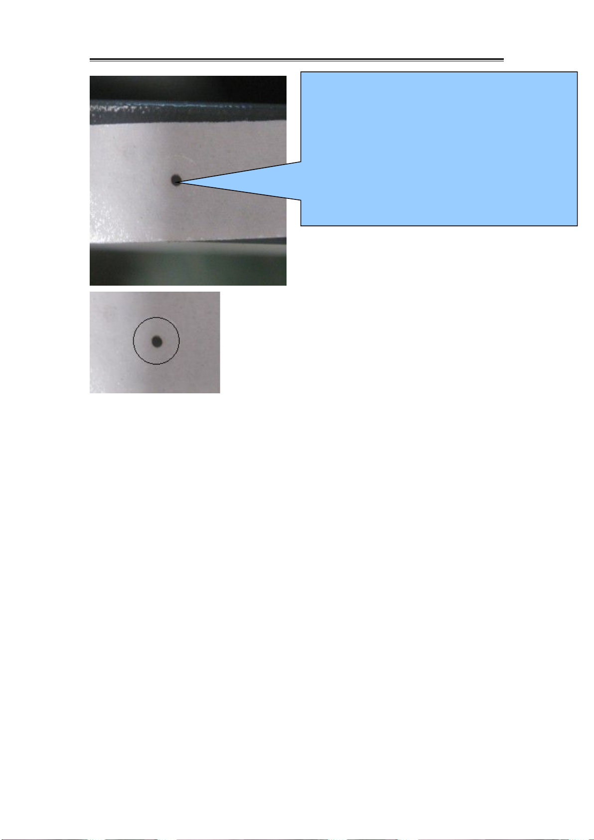
4.2.2.2 Laser Path Debugging Steps
Work Principle:Put the reflected Facula as the point,and then put it in
the center through by adjusting the position of the laser tube.
Detailed Steps:
Laser shoot out from the laser tube, reflected by first, second, third
reflection mirror, and then reaches the working table through focus lens.
Finally reach on the work table.
It's working theory is through multi-reflecting and focusing, to achieve
the best cutting and engraving effect. If light path isn't adjusted properly,
it may destroy laser tube, reflectors, lens and so on. Please re-adjust the
light path if it tilts. Following steps for your reference:
No.2 Screw
Before adjusting the laser, outlet of laser tube
and circular hold on laser head should be
consistent.
The laser beam should shoot on on the right
side of the central point of the mirror. It's
better for reflection.
Adjusting method: adjust first mirror bracket.

2
From the first reflector to second reflector, the laser beam should
be fell on the same point from both nearest and farthest position to
the first reflector.
Upper--please adjust No.1 screw;
Lower--please adjust No.1 and No.2 screw;
Left—please adjust No.2 screw;
Right—please adjust No.1 and No.2 screw.
No.2 Screw
No.3 Screw
If light on same point and not on right
side of the center, please adjust
No.11,12,13 screw.
No.11 Screws (Two)
No.12 Screws (Two)
No.13 Screws (Two)
No.1 Screw

No.23 Screw
No.21 Screw
No.22 Screw
No.11 Screws (Two)
Accordingly, from second reflection mirror to
third reflection mirror, laser should fall on the
same upper side of the center slightly.
Upper—adjust No.21 screw;
lower—adjust No.21,22 screw;
Left—adjust No.22 screw;
Right—adjust No.21,23 screw.

If light is on same point and not on
upper side of the center slightly:
Left or Right -- you need to adjust
No.11 screw;
Upper / lower -- please adjust the
position of laser tube.
No.31 Screw
No.33 Screw
No.32Screw
put a double sides adhesive tape on the
outlet of the laser head, take left hand side
as left, right hand, right;laser tube side, front
and people where we stand, backside. Just
as picture shows
Picture A
Attention:
Laser is invisible light but can do harm to human body. Please keep away
from the laser path when debugging. The operator must master the basic
knowledge of laser machine.
4.2.3Test Processing
After debugging of light path, put the working material on the working
table, then spin the laser head clockwise(overlooking the laser head), to
make it stay in the focal length height. After adjusting the focal length,
then anticlockwise the lens cone nut. Then move the laser head to the
designated spot, finally open software to design patterns you need, set the
processing way, speed and power. Download and name it, then machine
could cut or engrave the files as you command. Take following picture as
a reference.:
Notice:Only need to operate the control panel if there is Auto Focus
System.
The Facula should be in the center of the
outlet as Picture A
If not:
Left -- adjust No.32 screw;
Right -- adjust No.31 and 33 screw;
Front -- adjust No.32 and 33 screw;
Back -- adjust No.31 and 32 screw.

5. Simple operating instructions
Before operation, please electrify the equipment, then connect the
machine USB and computer USB with USB data line.
5.1 Simple operating instructions
A. Double click on ‘RDCAMSetup6.exe’ in the disk then indicate the
dialog box as below:

B. Click【Install】button. Installation interface shows up as below:
C. Click Firstly. The following dialog box shows up.
D. After confirming USB data line is connected well, click “ok”.The
following dialog box shows up.

E. After installing USB drive, click
to install software.
After that, the following dialog box will show up and indicate that the
software has been installed successfully.
Esc:
F.After finishing all installations, click【
】
to end up installation process.
The user may need to install some different software (install external
software while installing LaserWork). So after finishing all installations,
the dialog box cannot close automatically. The user can end up
installation by clicking
【
】button.

5.2Data line using operation
Before operation, the machine has been started. All accessories such as
water chiller and pump can function well
5.2.1 Parameter Matching
Different machines have different versions.
The purpose of reading parameters is to match “Supplier Parameter” and
“User Parameter” in main board with parameters in software.
Double Click the Software“RDWorksV8”
Click the “Vendor Setting” in the “File”as below:

Insert the Password“rd8888” :
Click “Read”after enter into the interface:
Click “user” as shown in the following picture.Click”Read”:

Attention: if changing main board or parameters, please first go through
“Read” Then find parameters of CD or U disk and go through “Open”
and“Read
In the U disk or CD along with the machine, find the file folder named by
machine serial number.

You can check“CHANGJIA.RDVSet”after open it
:
Click Open
Files of
Machine with

After opening it,“Insert Succeed shows up.
Click “User” as shown in the following picture.According to the
supplier’s setting mode, follow the sequence of read—open—write to
import user parameters.
Click Open

After importing parameters of the supplier and user, close the software.
Reopen the software, you can use it normally.
5.2.2 Make simple pictures&Set picture layers
A .In the software, choose “Rectangle”and draw a simple square. Then
modify the size

B. Click “TEXT”.
Click once in the drawing zone.In the dialog box, edit text and click
“OK”button.
Modify the Size

Select the Color Layer after finish the text.:
Color Layer Area

Download Here
5.2.3 Set working mode
Select the Power and Speed according to the materials.(take the
parameter sheet as reference)
5.2.4 Download files
Click “Download”,Name the file and
confirm “ok”

5.2.5 Equipment Operation
On the main board, press”File”

Find your file, press”Enter”
Put your processing object in a right position, adjust a proper focal
distance.

“Origin”-- “Frame”--“Start-Pulse”
5.3 U-disk Operation
(same as Data Line Operation will not be illustrate again)
After set parameters of “Power” “Speed” “Processing Mode”save the file
into U-disk.
Origin
Start-Pulse

Connect U-disk into U-FLASH.
Choose “Read U disk” , Press “Enter”,
Choose your file which need to be processed, choose “Copy to Memory”,
Press”Enter”.
(Notice: the file name you will process should not be the same as your
previous imported file in the main board, if so, U-disk file will not
allowed to import again, you need to change another name then import it
into the main board)
Find the your imported file, then start/cut.
Save To U
File

6. Rotary Processing
6.1 Electrical Installation
6.1.1 Rotary Connection
Place the rotary on the working table and keep flatness.

Unplug the aviation plug that connected with driver.
Connect the male connector on driver with female connector on the
rotary.
6.2 Software Operation
Start up: Reset machine with Metal. Click the limited switch on Y-axis
TWO TIMES to help it reset. Pictures as followed:

6.2.1 Software Setting
Open the software”RDWorks”, File--Vendor Setting--Vendor Parameter
Password: rd8888--OK
Press “Read”, then close the dialog box.

NOTICE: RECORD ALL INITIAL PARAMETERS BEFORE THE
FOLLOWING MODIFICATION.
It has to be recovered when not use rotary.
In the right side of software, choose “ User”--Press “Read”

In the following “Cut Parameters” with red frame, REMOVE A ZERO,
like: 200.00-20.00, 3000.000-300.00, 20.000-2.000, 400.000-40.000,
3000.000-300.00, refer as followed:
Press “Write”

6.2.2 Cutting Test
“Circle pulse” will be changed according to the diameter of processing
object. Formula in the following:
Actual Pulse= {theoretic pulse * theoretic length}/actual length
Illustration: engrave a 20mm line on the bottle (diameter=65mm)
(1) Output--check the box “ enable rotate engrave”--Circle Pulse:
1000--Diameter: 65mm, refer to the following:
Noted: a. The box “enable rotate engrave” should be checked.

b. Diameter: processing object’ s diameter
(2)Draw a 20mm line in the software, parameter setting: suggest “max
speed=15mm/s”, “ max power=15%”, download.
(3) Stick a pare tape on the surface of processing object.
(4) Set right rotary, adjust the processing object in a right position, pull
laser head just above the processing object.

Notice: Direction of rotary confirmation:
Press Direction Button on the control panel, if the direction of rotary
wheel is apposite with the button on control panel, that is correct. If is not,
the engraving image will be mirror image, Then turn the rotary 90 degree.
(5) Adjust proper focal distance then start engraving
(6) Measure the length of line

Through measurement, the length is 16.5mm, it is not matched with
previous setting parameter 20mm, so the circle pulse (10000) is not
correct.
(7) Revise circle pulse, and figure out the following according to
formula:
Actual pulse={10000*20}/16.5=12121
Then fill this value and diameter into the following parameter setting:

Notice:
A. The direction of rotary will influence the engraving effect, if direction
is wrong, the engraving image will reverse.
B. When you do not use rotary, don’t forget set the parameters into initial,
and removed the check of “enable rotate engrave ” .
7. Equipment maintenance and repair
7.1 Daily maintenance
Equipment's working environment could not be too scurviness. If
temperature is higher than 30℃, lower than 18℃, and if there is too
much dust, with severe air pollution, then the machine could be badly
damaged, failure rate goes up steadily. Various electric parts are easily
damaged under wet environment.
7.2Water tank's change and clean(suggest to change water and clean

water tank per week)
Attention: before machine starts to work, be sure that laser tube is full of
water and without bubble.
Recycling water's quality and temperature could affect laser tube's
lifespan directly. We suggest to use pure water, and control the water
under 35
℃。
If it's higher than 35, then need to change recycling water, or
add ice to water(we suggest customers choose water chiller, or use two
water tanks)
Clean water tank: firstly, switch off electric power, take off the water-inlet
water tube to let water inside laser tube go to water tank. Open water tank,
take out water pump, clean dirt on it. After cleaning water tank, changing
new recycling water, put back the water pump. Connecting water tube on
pump to water-inlet gate, and other joints. Connect electric power to
water pump separately for 2-3 minutes(make laser tube be full of
recycling water).
7.3Exhaust fan's clean
After long term's using of exhaust fan, it would accumulate much solid
dust, which could make exhaust fan produce big noise and it is also not
good for eliminating wasted air and smell. When it occurs that exhaust
fan is not good enough to suck and eliminate air, firstly close the power,
take off air-in and out tubes, remove dust inside, bottom up the exhaust
fan, roll fan blades inside until it's totally cleaned. Finally, set up the
exhaust fan.
6.4 Reflectors' and lens' clean(suggest to clean before working
everyday, equipment should be under power off situation)
There are 3 reflectors and 1 lens on Laser equipment(the first reflector is
set on emission exit of laser tube, mean on the laser equipment's
upper-left side, the second reflector is on the left side of transom, the
third one is on the top side of laser head, lens is inside in lens cone), laser
beam is transmitted through these reflectors and lens. It's easily for
mirrors to smear dust and other dirt, which could result in laser's loss or
mirrors' damage. The first and second reflector needn't have to be taken
off when do cleaning. Take lens wiping paper with leaner to wipe
reflectors from center to edge. The third one and lens need to take off

from lens frame and clean them with same way, and put back after
finishing.
Attention:①wipe the reflectors and lens softly, do not damage their
surface coating film;②handle gently during wiping to avoid falling
down;③the convexity side must be arranged downward.
6.5 Guide rail's clean (suggest clean half a month, power off operation)
As key parts, guide rail and straight line axis play role of guiding and
supporting. In order to guarantee higher processing precision, higher
requirement for guide rail's guiding accuracy and straight line axis'
moving stability. During processing, the material processed can produce
much corrosive dust and smog. After long term acceleration of these dust
and smog on guide rail and straight line axis, equipment's working
precision can be affected and can also form corrosive spot on them, thus
shorten machine's lifespan. For maintaining equipment's normal and
stable work, make sure the products' processing quality, please do well in
guide rail and straight line axis' daily maintenance.
Attention:For cleaning guide rail, please prepare dry cotton cloth,
lubricating oil(sewing machine oil can be adopted).
6.5 Light path's examination
Laser engraving equipment's optical system consists of reflectors'
reflection and lens' focusing. In light path, lens doesn't exist excursion,
however, the three reflectors are fixed through machinery, so possibility
for excursion can be big. Generally speaking, the light path could be
skewing, we suggest users to test it before everyday working.
6.6 Slide block's maintenance
Slide block is one of key parts. It's role is to guide and support, same as
guide rail and straight line axis. In order to guarantee it's normal work,
lubricating oil must be added periodically.
8. CO2 Laser Tubes of Glass Usage Considerations
8.1 Before using, please connect the water pump/chiller first, adopts
lower side in and higher sider out principle, adjust water-outlet tube's
position, guarantee cooling water is full of cooling tube. There should be
not any bubble inside the laser tube, then power on.Requirement: cooling

water should adopt software(distilled water or pure water), and frequently
pay attention to cooling water's temperature, should be within 12-30℃. It
should not be too low or too high, especially in summer. Once water's
temperature is too high, should change cooling water in time or stop the
equipment for some time. Cold area should guarantee water should not be
freeze, especially when machine stops working, cooling water must not
stay inside in laser tube in case there is any frozen cooling water to cause
explosion.(Specially attention: users who use AC, cooling water tank
must connect with ground)
8.2 The two supporting points should be on the 1/4 point on the laser tube,
and guarantee water-flow at the level of 2L-4L per minute, or the effect is
not good, which could lead to mode hopping, light spot becomes several,
thus result in power going down. Cooling water's water-outlet tube must
be submerged in water, or there will occur laser tube is not filled totally
with water when power off and on.
8.3 Pay attention to protect laser tube's exit side, to avoid smog sputtering
on the exit surface and pollute the it, or power will be lower down. The
mirror on exit side can not be cleaned with cotton ball and other tools, or
it's power will be severe affected. Correct methods for cleaning this
mirror:
●
once the mirror is polluted, do not open the laser tube
● obliquely blow mirror's surface
● use pure alcohol compressed by cylinder needle to spray the mirror
surface
● open the laser after alcohol volatilizing totally
If above methods have no effects, professional stuff need to use cotton to
clean it's surface from center to edge vortically with cotton ball dipped in
alcohol. The best way is to protect mirror from pollution. Special
attention: don't use ACETONE to clean the mirror.
8.4 During the debugging, through adjusting laser tube's supporting
position or rotating laser tube's direction to reach the best effect, then fix
the laser tube.
8.5 Must pay attention: avoid dust acceleration on high voltage electrode,
keep dry. Be away from metals as much as possible in case any fire

hazard. In order to protect high voltage sheath from dust, please entangle
plastic wrap on it.
8.6 During using of laser tube, there should be no scale inside laser tube
in case to cause water plugging, thus affect cooling effect. Once there is
any scale, use 20% diluted hydrochloric acid clean it.
8.7 Laser tube belongs to glass products, fragile. Avoid local stress when
arranging laser tube.
8.8 To use laser tube properly, save laser power. Laser tube's best power
is 80% of rated power.
9. Common troubleshooting
Symptoms
Problem analysis
Processing method
No laser beam
during working
1. Firstly, check if laser tube itself works
normally(the exit of laser),if it works
normally
Test if mirrors are damaged
or not, light path is skewing.
2. The exit of laser tube has no laser, then
check if water recycling works
normally(see if water flow is smoothly), if
no water flow or it's not smoothly
clean water pump, dredge
water tube
3. Water recycles normally, then check if
laser power guiding light is bright or not,
fan rotates or not, if not
Laser power goes bad, need
to change laser power
4. Press "laser", if there is no light
Laser power or laser tube has
problem
5. If there is light
Water protector goes bad,
need to change

6. If short circuit water protector, there is
still no light
Main board or wiring board
has problem, need to change
Scanning
becomes
shallow
1. Check working light's intensity and
speed, if speed is too fast, intensity is
small, water temperature is too high
Enlarge light's intensity,
lower down speed, change
recycling water
2. Check depth of crisperding, and see if
it's normal, if it's normal,
Increasing graphics resolution
or scanning precision
3. Crisperding is still shallow, or both
occasionally,
Check if Mirrors are dirty or
damaged, light path is
skewing
4. Connect ampere meter, if it can reach
20MA, but the depth is still shallow
Laser tube aging, need to
change laser tube
Laser is not
stable,
sometimes has,
sometimes does
not
1. Check if the mirrors are too dirty or if
they are damaged, light path is skewing or
not
Clean or change mirrors,
adjusting light path
2. Mirrors' light path is normal, then check
if water recycling is normal or not, if it is
not normal,
Clean or change water pump,
dredge water tube
3. Water cycling is normal, it's may water
protector's problem
Change water protector
4. If problems remain, main board, laser
power, laser tube, all possible to lead to
this phenomenon
Change all part above
alternately, and check the
reason
Output
patterns, but
the size is not
right
1. Check "Coreldraw" and see if Graph
Plotter unit is 1016 when it outputs PLT
1016Change graph plotter's
unit to 1016
2. See if resolution ratio is right or not
Recount resolution ratio
Equipment
reset abnormal
1.The direction is right when reset, but
reaches the vertex,the transom can not
stop(if new machine, please check main
board's parameter first, if it's right)
Check if it's stuck during
moving, main board, tool
sensor problem, change
2.Transom resets normally, laser head
doesn't move, maybe tensioner get stuck or
motor axis break, parameter is wrong
Change tensioner or small
motor, modify parameter,
check motor line's clip

3.Contrary to transom's movement, and
strike the side
Main board parameter is
wrong. Stop the machine and
modify main board
parameter. Re-down load
configuration
4.Drivers or Motors' problem
Change drivers or motors
Equipment stop
engraving, skip
engraving or
disordered
engraving
1.Check equipment's grounding situation,
and check grounding line is standard or
not(resistance to ground should not be
bigger than 5Ώ)
Modify grounding line to
reach standard requirement.
2.Check if the original pattern has mistake,
such as pattern is cross, leaking, or lack
something
Correct mistakes in patterns
3.If other patterns don't have this problem,
only some one has such problem
Patterns and date mismanage,
need to make working sketch
again
4.Problem remains
Maybe it's computer's serial
port, engraver's main board's
problem
Appendix 1
After-sale warranty of Laser Engraving Cutting Machines
First of all, thank you very much for purchasing a Bodor product. In
order to guarantee the smooth processing of after-sales service, we will
make the following announcements:
General principles
1. We are responsible for the maintenance of facilities which are
within the Warranty conditions.
2. Users must keep the machine's integrity and independence during
operation. In the following situation, our company will not take any direct,
indirect or joint liability. Futhermore, if any equipment is damaged or
there are any losses in either economic or reputation to our company due
to the following situation, we, Bodor company, reserve the right to

investigate any legal liability.
1) Using the equipment in an environment that it was not designed
for..
2) Altering the machines privately, including, adding parts, reducing
parts, dismounting, using another brand's parts, etc.
3) Human damage or doing operations and maintenance without
following the requirements in the instructions.
4) Damage caused by movement or transportation.
On condition of not influencing the machine's performance, our
company reserves the right to change the product's specifications and
name the products before informing the customer.
Our company is responsible for the quality and performance of the
machine we sell. However, we are not responsible for other indirect
obligations and responsibilities.
Detailed Principles
Equipment Warranty: 2 years. Calculated from the production date in
machine’s nameplate.Specific details are as below:
2 .Laser module Warranty:
(1)RF Tube’s and fiber module’s warranty: 1 year
(2)Standard CO2 Glass Laser Tube’s warranty: 40w ~ 80w: 4
months ;100w ~ 150w: 6 months.Warranty of related laser power supply
is one year.
(3)RECI Laser Tube’s warranty: 10 months .Warranty of related laser
power supply is one year.
(P.S. Laser module’s warranty date calculated from the production
date in laser module tag. CO2 Laser Tube is suggested to be used in
nonmetal and opaque materials’ engraving and cutting,and should be keep
clean. Improper use will cause the front lens to breakdown. Any
breakdown of the front lens and an incomplete laser tube will not be
guaranteed.
3.The warranty does not include consumable parts, such as glass mirrors,
belts, switches, gas nozzles ,foots/wheels, keys/press boards, etc.
4.Warranty of peripheral devices (if the machine has them):

Warranty of peripheral devices is 1 year, calculated from the production
date in the device’s tag. Maintained by device’s manufacturers as
standard,Our company assist maintenance. Peripheral devices including
water-chillers, fans, air pumps, water pumps etc.(If the machine has
them).
Accessories repair and shipping cost
Within the warranty period:
For free repair or replacement of accessories, the buyer should bear
the shipping costs from their local place to our company if it needs to
tested, repaired or replaced.
If the failure cause by the parts quality after testing(non human
factors and use environment etc.), it will be repaired or replaced free of
charge, and Bodor company will bear the return shipping cost. If the
failure doesn’t cause by the parts quality, the buyer should pay the repair
fees and round-trip shipping cost.
P.S. The repaired parts should be returned to our factory. if the buyer is
in arrears of spare parts, Bodor company will cancel the warranty terms
of the machine).
Outside the warranty period:
The buyer should paid for repairs and round-trip shipping.
Door to Door Service Policies
Bodor supplies door to door services all over the world. Charging
standards and service processes are as below:
(A). Charging standards:
1. Technician visa fees, domestic travel expenses (including
transportation cost occurred during handling documents);
2. Training and maintenance fees: $100/day/person(take the time of
landing and starting off of plane in customer’s country as standard);
3. International round-trip tickets (reserved and paid by the buyer, and
supply the e-ticket information to our company );
4. Abroad accommodation(arranged and paid by the buyer)
(B).Overseas training/maintenance processes:
1. Bodor company will calculate the fees of item 1 and item 2 above,

and then inform the buyer. After the buyer pays the fees, Bodor company
will arrange for the technician to apply for a visa.
2. We will inform the buyer after the technician gets the visa. The
buyer should supply the round-trip ticket information mentioned above in
item 3, and arrange accommodation from item 4 after the technician
arrives.
3. Only after getting the approval of Bodor company, the buyer can
apply for an extension for the training and maintenance.The buyers
should pay for the“extend training and maintenance service fees”before
the start of the extend service.
Appendix 2
Reference Parameter Setting List for Cutting/Engraving:
40W PARAMETER SETTING
Thickness(mm)
Speed
(mm/s)
Max Power
(%)
Min Power (%)
Acrylic
3mm
10~15
50~75
50~70
6mm
4~5
65-80
65~75
8mm
2~5
60~80
65~75
Cloth/ Paper
1mm
100
25
22
Leather
2mm
100
35
30
MDF (WOOD/PAPER)
3mm
306055
6mm
107065
9mm
38075
Glass
300~600
18-65
Interval 0.03-0.1
Acrylic
300-600
18-65
Interval0.03-0.1
Double-color board
30-50
40~50
Cutting
Double-color board
300~600
23~30
Interval0.03-0.1

80W PARAMETER SETTING
Material
Thickness
Speed
Working Max
Power(%)
Corner Min
Power (%)
Usage
Remarks
Acrylic
3mm
10-20
40-70
35-70
Cutting
6mm
5-10
70-80
65-80
Cutting
8mm
28075-80
Cutting
Lower than
the focal
Block
0.5mm
10mm
1-28075-80
Cutting
Lower than
the focal
block 1mm
Cloth/ Paper
0.5mm
100-400
20-50
20-50
Cutting
Leather
0.5mm
100-400
35-50
35-50
Cutting
Double-color
board
1.5mm
30-50
45-55
Cutting
Marble
300-600
25-75
Engraving
Interval
0.03-0.1
Acrylic
300-600
25-75
Engraving
Interval
0.03-0.1
Wood
300-600
25-75
Engraving
Interval
0.03-0.1
Double-color
board
300-600
25-75
Engraving
Interval
0.03-0.1
Notice:
Above parameters are just for your reference, please change accordingly
based on your materials.
 Loading...