


1
Laguna Tools
2018
Smartshop M
User guide for Smartshop machines
equipped with the RichAuto B57E
Basic operaons, Quick Start, Mutli-Tool Programs, Creang a
G-code file with V-carve, Maintenance and Troubleshoong,
Installaon Outline, Default Sengs
Laguna Tools
12/1/2017
ver. YLW
Chapter:

Page 2 of 23
Chapter:
2
TAB LE OF CONTENTS
1 Introduction ............................................................................................................................................... 3
2 Document Key............................................................................................................................................ 3
3 Basic Operations ........................................................................................................................................ 3
3.1 View of Machine ................................................................................................................................................ 3
3.2 Turning ON the machine .................................................................................................................................... 4
3.3 Homing ............................................................................................................................................................. 5
3.4 Basic Button Functions ....................................................................................................................................... 5
3.5 Changing Tools .................................................................................................................................................. 6
4 Quick Start Section .................................................................................................................................... 6
5 Multiple tool program .............................................................................................................................. 10
5.1 Setting tool offsets ...................................................................................................................................................................... 10
5.2 Setting XY work origin ................................................................................................................................................................ 11
5.3 Setting Z work origin .................................................................................................................................................................. 11
5.4 Run program ................................................................................................................................................................................ 12
6 Understanding Work Coordinate systems ............................................................................................... 13
7 Tool Cone Setup ....................................................................................................................................... 13
8 Maintenance and Troubleshooting .......................................................................................................... 14
8.1 Cleaning and Lubricating the Mechanics ................................................................................................................................. 14
8.2 Resetting Tool locations ............................................................................................................................................................. 14
8.2 Tool touch off - ToolSettingZ adjustment ............................................................................................................................... 15
9 Creating a G-Code file .............................................................................................................................. 16
10 Appendix .................................................................................................................................................. 21
10.1 Hiteco Spindle Pneumatic Specifications ............................................................................................................................... 21
10.2 Installation Outline ................................................................................................................................................................... 22

Page 3 of 23
Chapter: 1 Introduction
3
1 INTRODUCTION
This document is intended to provide general information on how to operate the Smartshop M
machine, equipped with a RichAuto B57E controller. For accelerated start up, refer to quick start
section.
2 DOCUMENT KEY
Bold text - Hard Button click
Italicized text - List Selection
Red text - Warns the user of potential hazards
Blue text - Additional information
3 BASIC OPERATIONS
3.1 VIEW OF MACHI NE
Figure 1. Front of electrical cabinet, and view of spindle

Page 4 of 23
Chapter: 3 Basic Operations
4
3.2 TURNING ON THE M A C H I NE
1. Turn the rotary switch to the ON position.
2. Turn the key to the ON position.
3. Press the Control Power ON/OFF button located on the control panel.
Figure 2. Front and rear view of machine

Chapter: 3 Basic Operations
5
3.3 HOMING
When the B57E controller is first powered on, the user will be
prompted with the HomeTypeAtStart window.
The machine needs to be homed each time the machine is
powered.
1. This resets your machine coordinates origin, relative to the
home switches and flags.
2. The tool locations are relative to the machine origin.
The default selection is
All axis home
.
1. Press REF/OK to begin homing all axes, or select another option.
3.4 BASIC BUTTON F U N CT I O N S
The RichAuto motion control system uses 1-button and 2-button combination functions.
Only the most used button functions are covered in this section.
Page 5 of 23
Chapter: 4 Quick Start Section
6
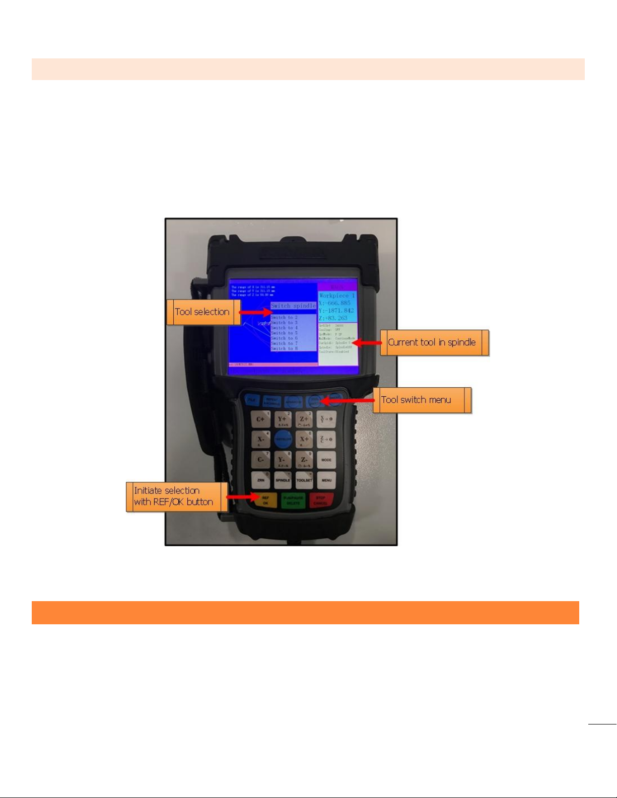
3.5 CHANGING TOOLS
1. A tool can be inserted or removed two ways
o Manually - Using the tool release button on the side of the spindle (figure 1)
o Automatically - Using the Tool Switch button
Press ToolSwitch button
Use up and down Y buttons to highlight tool selection
Press REF/OK button
Page 6 of 23
4 QUICK START SECTION
This section is a work flow, from turning the machine on, to starting your program.
This walkthrough assumes only TOOL 1 is used.
1. Power on machine (Section 3.1).
2. Home machine (Section 3.2).
3. Verify that the machine is connected to an air supply.
Chapter: 4 Quick Start Section
7
a. The tool changer needs 6-6.5bar or 87psi-95psi.
b. Use the pressure regulator (figure 2) on the back of the machine to adjust air pressure.
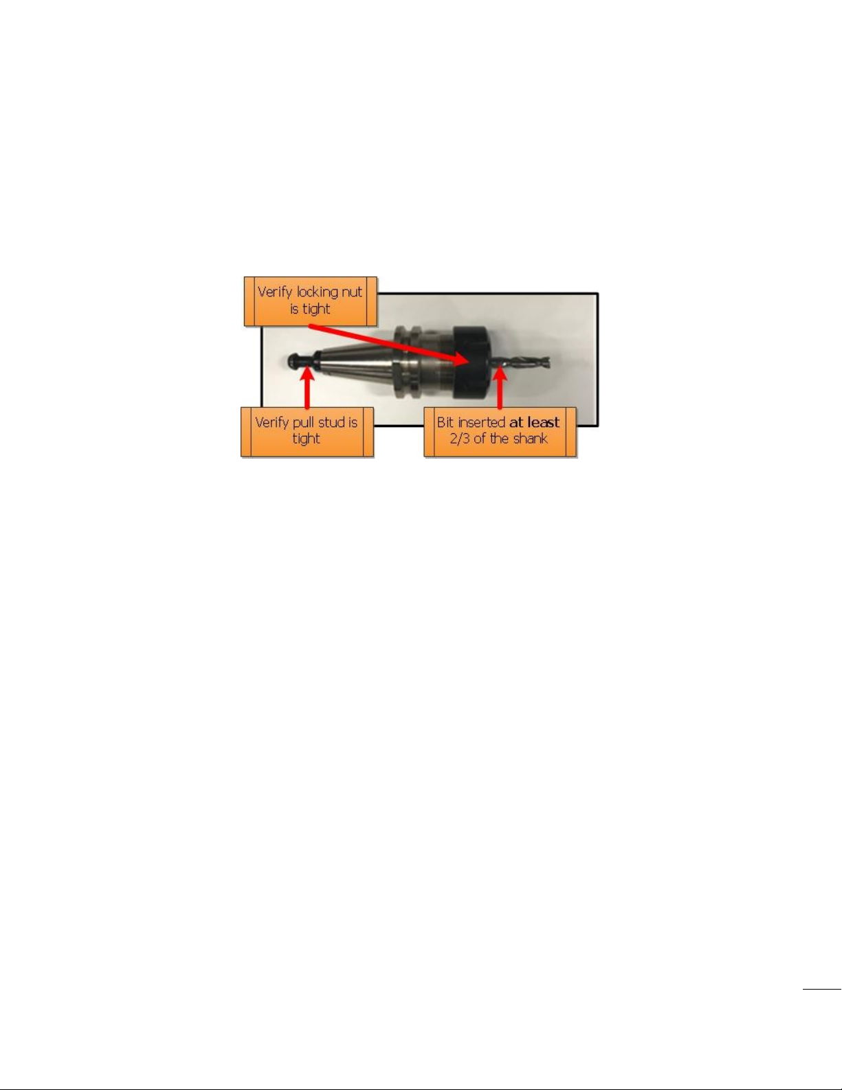
4. Set up a tool cone with the router bit you intend to use (Section 7).
a. Use the manual tool release button located on the tool head to load the tool cone
into the spindle.
b. It is important that the spindle releases and engages the tool cone repeatedly.
This quick check will prevent an error condition.
Page 7 of 23
Figure 3. Tool cone with locking nut, collet, and router bit
5. Transfer your g-code program onto a USB and transfer into the controller's internal memory.
When running a program directly from a USB, memory transfer is less reliable.
It is recommended to store the program in the controller's internal memory.
a. MENU -->
b.
Machine Configuration -->
c. Scroll down to
d. Select
e. Select the
f. Press STOP/CANCEL a few times to return to the controller home screen.
6. Load Program into viewer
a. Press FILE -->
7. Mount workpiece to the table top.
a. This can be done with the supplied table clamps (Figure 3).
b. There exist a multitude of ways to secure your workpiece.
Find what method works best for your application before proceeding.
c. Always consider clearance between the router bit and table clamps.
Menu Function User Interface
REF/OK
Operate File,
Copy File,
UDisk File
Internal File
press REF/OK
you want to copy press REF/OK
then Press REF/OK
--> REF/OK --> select your program --> REF/OK
--> REF/OK
Chapter: 4 Quick Start Section
8
When the machine changes tools it will need to travel to the back of the machine
during program execution.
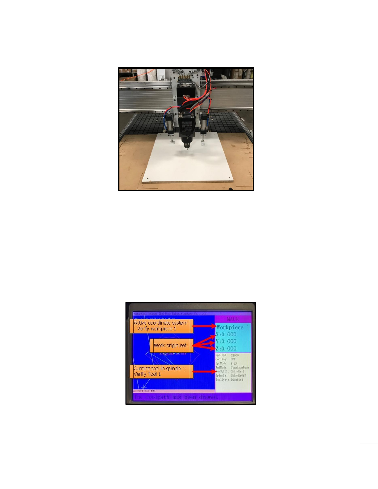
Figure 4. Simple workpiece setup
Page 8 of 23
8. Verify coordinate system (figure 4).
a. Workpiece 1 should be selected.
i. To change to workpiece 1, Hold MENU --> press C+/1 button, then release
both buttons
9. Verify which tool cone is currently in the spindle and compare to the CurSpindl parameter
on the controller run screen (figure 4).
a. If current tool number is not tool 1, then switch tools using tool switch function (3.4).
Figure 5. Control screen after loading program, and setting work origin.
10. Jog the spindle to the XY origin point. This is determined when the CNC program is created.
a. If you are using Vectric's V-Carve software, it is called the XY datum position.
 Loading...