


CNC Lathe 3-Axis
Manual
LAGUNA TOOLS
2072 Alton Parkway
Irvine, California 92606
Ph: 800.234.1976
www.lagunatools.com
Model Number: MCNC Lathe 1000-0233
© 2018, Laguna Tools, Inc. LAGUNA® and the LAGUNA Logo® are the registered trademarks of Laguna Tools, Inc. All rights reserved.


Table of Contents
Page Number
Safety Rules 4
Warranty 5
Noise Emission 6
Specification Sheet 6
Receiving Your CNC Lathe 6
Introduction to Your CNC Lathe 6
Parts of CNC Lathe 7
Additional Instructions for the Use of the CNC 10
Where to Locate Your CNC Lathe 10
Unpacking Your CNC Lathe 11
Assembly and Operation 12
Maintenance 17
Troubleshooting 18
3

Safety Rules
As with all machinery, there are certain hazards involved with the
operation and use. Using it with caution will considerably lessen the
possibility of personal injury. However, if normal safety precautions are
overlooked or ignored, personal injury to the operator may result. If
you have any questions relative to the installation and operation, do not
use the equipment until you have contacted your supplying distributor.
Read carefully before operating the machine.
1. Keep the working area clean and be sure adequate lighting is available.
2. Do not wear loose clothing, gloves, bracelets, necklaces or ornaments.
Wear face, eye, respiratory and body protection devices as indicated
for the operation or environment.
3. Be sure that the power is disconnected from the machine before
tools are serviced or an attachment is to be fitted or removed.
4. Never leave the machine with the power on.
5. Do not use dull, gummy or cracked cutting tools.
6. Be sure that the keys and adjusting wrenches have been removed
and all the nuts and bolts are secured.
4

Limited Warranty
New machines and accessories sold by Laguna Tools carry a one-year warranty
effective from the date of shipping. Machines sold through dealers must be registered
with Laguna Tools within 30 days of purchase to be covered by this warranty. Laguna
Tools guarantees all new machines and accessories sold to be free of manufacturers’
defective workmanship, parts and materials. We will repair or replace, without charge,
any parts determined by Laguna Tools, Inc. to be a manufacturer’s defect. We require
that the defective item/part be returned to Laguna Tools with the complaint. Any
machines returned to Laguna Tools must be returned with packaging in the same
manner in which it was received. If a part or blade is being returned it must have
adequate packaging to ensure no damage is received during shipping. In the event the
item/part is determined to be damaged due to lack of maintenance, cleaning or
misuse/abuse, the customer will be responsible for the cost to replace the item/part,
plus all related shipping charges. This limited warranty does not apply to natural
disasters, acts of terrorism, normal wear and tear, product failure due to lack of
maintenance or cleaning, damage caused by accident, neglect, lack of or inadequate
dust collection, misuse/abuse or damage caused where repair or alterations have been
made or attempted by others.
Laguna Tools, Inc. is not responsible for additional tools or modifications sold or
performed (other than from/by Laguna Tools, Inc.) on any Laguna Tools, Inc.
machine. Warranty maybe voided upon the addition of such described tools and/or
modifications, determined on a case-by-case basis.
Software purchased through Laguna Tools Inc. is not covered under this warranty
and all technical support must be managed through the software provider. Software is
non-refundable.
Normal user alignment, adjustment, tuning and machine settings are not covered by
this warranty. It is the responsibility of the user to understand basic machinery
operation, settings and procedures and to properly maintain the equipment in
accordance with the standards provided by the manufacturer.
Parts, under warranty, are shipped at Laguna Tools, Inc.’s cost either by common
carrier, FEDEX ground service or a similar method. Technical support to install
replacement parts is primarily provided by phone, fax, e-mail or Laguna Tools
Customer Support Website. The labor required to install replacement parts is the
responsibility of the user.
Laguna Tools is not responsible for damage or loss caused by a freight company or
other circumstances not in our control. All claims for loss or damaged goods must be
notified to Laguna Tools within twenty-four hours of delivery. Please contact our
Customer Service Department for more information.
Only new machines sold to the original owner are covered by this warranty.
For warranty repair information, call 1-800-332-4094.

Noise Emission
Notes concerning noise emission
Given that there exists a relationship between noise level and exposure times, it
is not precise enough to determine the need for supplementary precautions. The
factors affecting the true level of exposure to operators are clearly the amount of
time exposed, the characteristics of the working environment, other sources of
dust and noise, etc. For example, adjacent machines may affect the level of
ambient noise. It is possible that exposure level limits will vary from country to
country.
Specification Sheet
Spindle Motor
Spindle RPM 5,000 - 24,000 RPM Spindle
Controller Laguna HHC (Hand Held Controller)
Volts One phase machine 220v /30 amp
Ball Screw on Vertical Axis Yes
Rack and Pinion on Horizontal
Axis
Maximum Diameter 8"
Maximum Travel Length 46" or 72"
Machine Foot Print 73"L x 24"D x 65"H
Receiving Your Machine
Note: It is probable that your machine will be delivered by a third party. Before
you unpack your new machine, you will need to first inspect the packing, invoice,
and shipping documents supplied by the driver.
Ensure that there is no visible damage to the packing or the machine. You need
to do this prior to the driver leaving. All damage must be noted on the delivery
documents and signed by you and the delivery driver. You must then contact the
seller, Laguna Tools, within 24 hours.
3HP 3 Phase Industrial Induction Spindle,
Liquid Cooled
Yes
Introduction to CNC Lathe
The CNC Lathe is designed to give you years of safe service. Read this owner’s
manual in its entirety before assembly or use.
The advantage of the CNC machine is that it can, in most cases, fully machine
the complete job without it being removed from the Lathe so that you have
finished parts of high accuracy that are totally repeatable.
It can also produce intricate carvings with the purchase of the relevant software.
It is possible to reduce the amount of different machines in the shop, as the CNC
Lathe will perform a multiple of functions and is a must for serious woodworkers.
6
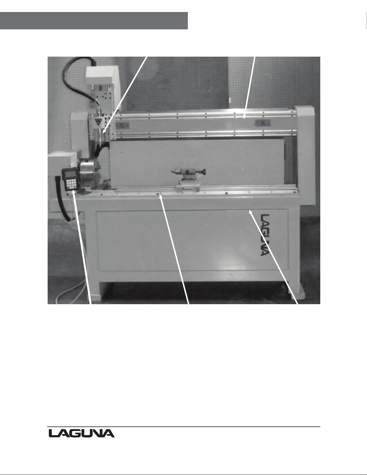
Parts of the CNC Machine
Router Spindle
Gantry
Hand-held controller
Note: Some of the photographs in the manual may not be identical to your
machine, but the principle that they show is the same for your machine.
Laguna Tools operates a constant improvement program, and changes to
machines are ongoing.
Bed
The bed of the machine consists of a heavy steel frame that supports linearbearing
rods. The tail stock slides along the rods and can be clamped in any
position to suit the job at hand.
Bed
Frame
7
Gantry
The gantry runs along the back of the lathe
and supports the linear bearing rods. The
router spindle moves along the rods on linear
bearings. It is moved along the length of the
gantry rack and pinion that is controlled by the
machine controller.
Frame
The frame is a heavy welded construction that
supports all the other parts of the machine.
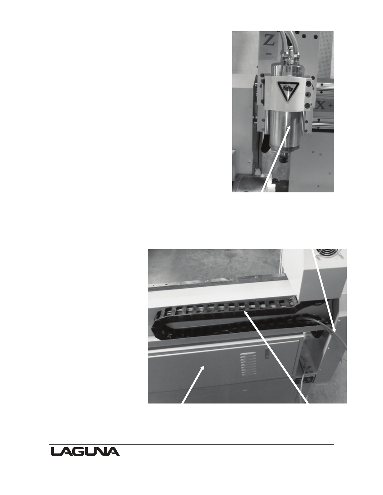
Router Spindle
The router spindle is moved vertically by a
precision ball screw system that is controlled
by the machine controller.
Note: If the spindle is run without cooling,
it could be damaged and fail.
Caterpillar track
The caterpillar track runs at the
back of the lathe and contains all
the electrical cables and the
motor water pipes.
Electrical cabinet
The electrical cabinet is
located at the back of
the lathe and contains all
the control equipment.
Water pump
The water pump provides
coolant for the router
spindle motor.
Running the router
spindle without the
cooling pump running
can lead to
spindle bearing
failure.
Router spindle
Motor water pipes
Electrical cabinet Caterpillar track
8

Tail stock
The tail stock runs on liner bearing rods. The tail stock slides along the rods and
can be clamped in any position to suit the job at hand.
Chuck drive
The chuck is driven through a right-angled
drive and is under the control of the on-board
computer.
Spindle vertical movement
The spindle is moved vertically by a motor that
rotates a precision ball screw.
The vertical movement is limited by a home
proximity switch.
Spindle clamp Spindle adjustment
Tail stock clamp Linear bearing rods
Spindle drive [cover
removed]
Tail stock clamp
Chuck drive shown with the
cover removed
Z Home limit switch
Precision ball screw for the Z axis
9

Machine data plate
The machine data plate is located at the
back of the machine and contains all the
machine information.
Hand-held controller
The hand held controller controls all
functions of the lathe.
Note: See separate manual for the
operation of the hand held controller..
Additional instructions
for the use of the CNC
Like all machines, there is danger associated with the machine. Injury is
frequently caused by lack of knowledge or familiarity. Use this machine with
respect. If normal safety precautions are overlooked or ignored, serious personal
injury may occur. As the CNC lathe is under the control of the onboard machine
controller, it is important that you are clear of the cutter when operating the
machine.
Where to locate your Machine
Before you unpack your machine, select the area where you will use your
machine. There are no hard-and-fast rules for its location, but below are a few
guidelines.
1. There should be an area around the machine suitable for the length of wood
that you will be machining.
Controller
2. Adequate lighting. The better the lighting, the more accurate and safely you
will be able to work
3. Solid floor. You should select a solid flat floor, preferably concrete or
something similar.
4. Close to power source and dust collection.
10

Unpack the machine
To unpack your machine, you will need tin snips, knife and a wrench.
1. Using the tin snips, cut the banding that is securing the machine to the pallet
(if fitted).
WARNING: EXTREME CAUTION MUST BE USED BECAUSE THE
BANDING WILL SPRING AND COULD CAUSE INJURY.
2. Remove the box from the CNC machine (if fitted) and any other packaging
material. The parts ordered with the machine will be packed on or inside the
machine.
Note: The machine is heavy, and if you have any doubt about the described
procedure, seek professional assistance. Do not attempt any procedure that you
feel is unsafe, or that you do not have the physical capability of achieving.
3. Use a forklift with sufficient lifting capacity and forks that are long enough to
reach the complete width of the machine.
4. Remove the securing bolts that attach the machine to the pallet (if fitted).
5. Approaching the machine from the front, lift the machine on the frame, taking
care that there are no cables or pipes in the area of the forks.
6. Move the machine to the required position and lower gently to the floor.
7. Level the machine so that the lathe is not rocking and the machine is level in
both directions using a spirit level.
11
Assembly and Operation
Cleaning the machine
Clean off any protection grease with WD40 or something similar.
The machine has steel parts that if not protected will rust, lubricate with WD40 or wax.
Use 30wt motor oil or lithium white grease lubricant or equivalent to lubricate the ball
screws. Wipe off any excess to reduce dirt and dust acumination.
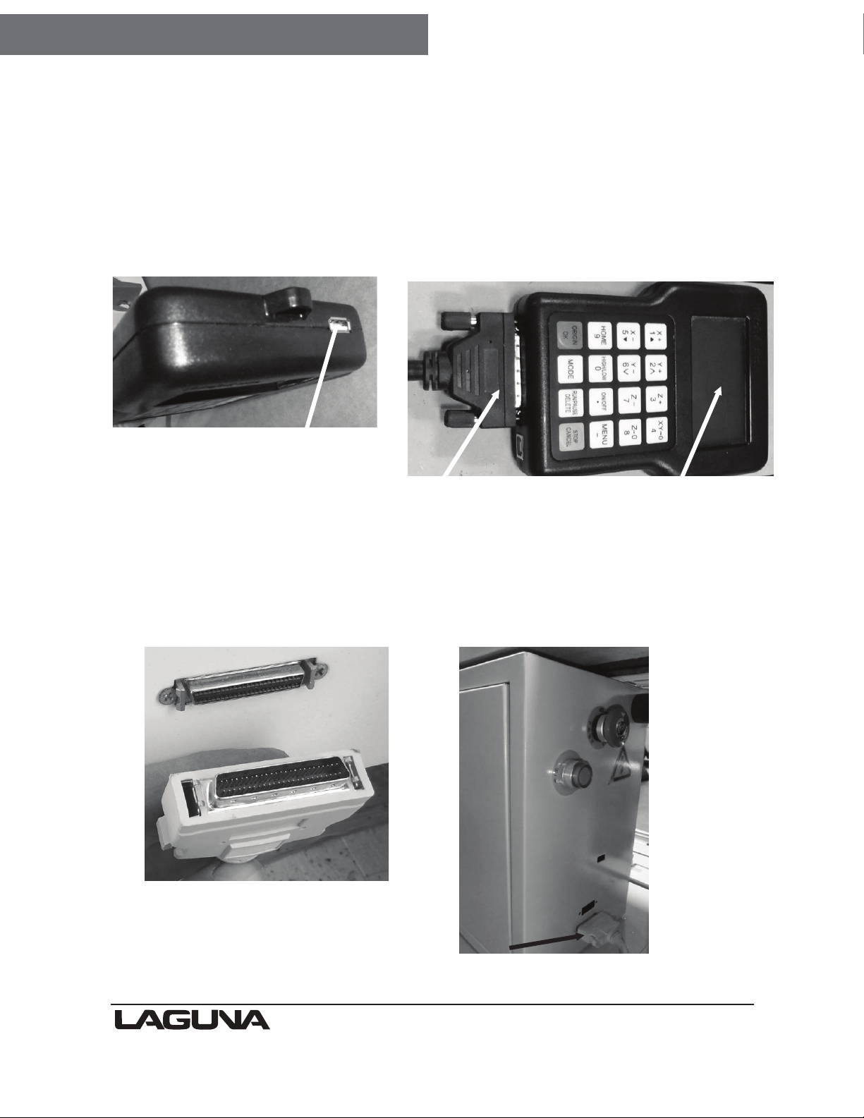
Assembling the hand-held controller
Note: See separate manual for the operation of the hand-held controller.
Memory stick socket
Connection cable
Fit the cable to the controller and ensure that the screws are finger tight. The
USB printer cable port is used to connect the controller direct into your computer.
Note: The connection port socket and plug only fit one way, so ensure that the
plug is the correct way up prior to assembling.
Cabinet socket
Hand held controller
Controller cable fitted to cabinet socket
12

Electrical connections for the machine
The main power cable and has no plug fitted, as it will be dependant on your
insterlation. Ensure that when installing the electrical supply to the machine, 220v
single phase is supplied.
It is recommended that you use a 30-amp breaker.
Note: When wiring the machine to your electrical system, keep your cable as
short as possible, and the cable should not be allowed to run along the floor, as
this will cause a trip hazard.
The second cable has a female electrical socket for connection to the water pump.
Note: A qualified electrician must carry out the electrical installation.
Water-cooled spindles
Water-cooled spindles will be provided with a 220-volt spindle-cooling pump.
The submersible pump needs to be submerged in a minimum 5-gallon
reservoir of water (the bigger the water tank the better).
Never run the spindle without cooling,
or the spindle will be damaged or destroyed. (WITHOUT WATER FLOWING
THROUGH THE SPINDLE, THE SPINDLE WILL OVERHEAT AND FAIL.)
Connecting the water pipes to the machine
There are two water tubes that come out of the machine. These are used to
provide cooling for the liquid-cooled router spindle.
Note: The water pump design may vary from the one shown.
Fitting the water pipe
Note: Never run the motor without the cooling being connected, or the
motor could be damaged.
You will connect one tube to the water pump, and the other will be placed in the
water container for the return water. It is not important which pipe is used as the
return.
Fit the pipe fitting to the pump.
Connect one of the coolant pipes to the water pump by pushing it into the connector.
Lightly pull on the pipe to ensure that it is connected correctly. Fill a container about
3/4 full with clean water. If the pipe needs to be removed from the pump, press the
outer ring into the fitting and gently pull the pipe out of the fitting.
Water pump
Pipe fitting
13

Note: You will need to provide a coolant tank with a minimum capacity of 5
gallons. If the shop temperature is high, the tank size will need to be larger. If
your shop is likely to be subject to freezing temperatures, antifreeze must be
added to the cooling water.
Lower the water pump into the container, ensuring that it is the correct way up
(water inlet lowest) and place the water return pipe into the container.
The logical position for the water container is close to the machine, as the water
pipes exit the machine at the back. Once the assembly is complete and the water
pump electrical connection has been made, lift the water return pipe up and
check that the water is flowing.
Place the lid onto the container to keep dust and dirt out of the container.
Check the container periodically, as the water will evaporate.
Note: If the spindle is run without cooling, it could be damaged and fail. It is
strongly suggested that the water pump is run for at least 5 minutes after
the spindle is switched off to remove residual heat.
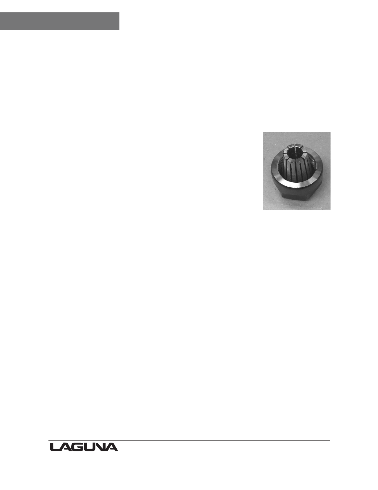
Fitting the router bit into the router head
Note: Before changing or fitting the router bit,
always disconnect the power to the machine.
Note: Collets and spindle collet hole must be
cleaned regularly. Ensure that the slots in the
collets are free of sawdust, as sawdust builds
up and will stop the collet compressing. If the
collet or spindle hole is not clean, the router
bit may not run true, and this will affect the
performance of your machine.
Spindle nut Collet
1. Select a pointed router bit and its relevant collet.
2. Fit the collet into the spindle nut. Press the collet into
the spindle nut until it snaps into place.
Note: The router bit must not be fitted into the collet until
the collet has been fitted into the spindle nut. With the
router bit fitted into the collet, the collet cannot compress
and snap into the spindle nut.
The face of the collet and the face of the spindle nut will
be close to flush.
Note: To remove the collet, hold the spindle nut and
press the collet on the side. The collet will compress and
pop out. Do not try to remove the collet while a cutter is
fitted, as the collet will not compress and pop out.
3. Fit the spindle nut and collet assembly onto the
spindle thread by hand.
4. Press the bit into the collet, but note that the flute of
the router bit must not be inside the collet and should be
a minimum of 1/16" outside the collet. Hold the router
spindle with the supplied wrench and tighten the collet
with a second wrench. Do not over tighten.
Note: Use this process for all other router bits that you need to fit but you will
have to change the collet if the shank of the router bit is a different size.
Tightening the spindle nut
Collet fitted to
spindle nut
14

Types of router bits
There are five basic types of router bits: straight, up
shear, down shear, combination (also called
compression), and form tools (round over, ogee, etc.).
1. Straight Router Bits
These are the standard router bits that are commonly
used with handheld routers and are readily available at
home centers.
2. Up Shear Router Bits
These bits have flutes that are spiraled upward (a standard twist drill is an
example of this type of bit). This bit design removes the chips from the kerf but
has a tendency to chip the top surface, especially veneers or melamine surfaces.
Ball nose router bits are a variation of the up shear bit design but have a
radiused end. These bits are typically used for 3-D surfacing applications.
3. Down Shear Router Bits
These bits are similar to the up shear but with an opposite spiral that actually
tends to pack the chips into the kerf. These bits prevent chipping the material
surface, especially with veneers or melamine surfaces.
Router bits
4. Combination (Compression) Router Bits
These bits combine the advantages of both up shear and down shear designs.
The top section of the tool is down shear to prevent chipping the top surface of
the material, and the lower part of the bit is up shear to prevent chipping the
bottom surface of the material.
Combination Router Bits are the preferred configuration for machining veneered
plywood as well as melamine-surfaced product. A variation of the bit is called the
“mortising compression” router bit. With this bit, the up shear portion of the bit is
less than 1/4" in length so that the bit can be used on 1/4" veneered plywood and
for dados.
5. Form Router Bits
Form Router Bits typically are available in standard profiles such as round over,
ogee, etc. Router bits that have a shape associated with them would be classified
with this group.
15

DO’S AND DON’TS
1. DO verify water level in the spindle reservoir.
2. DO lubricate all ball screws & linear guilds every 8 hours of run time. Use 30w oil
or lithium white grease lubricant or equivalent to lubricate the ball screws. Wipe
off any excess to reduce dirt and dust acumination.
3. DO keep your collets clean, as fine dust builds up and they get tight.
4. When doing carving work, it is necessary to use a much larger volume of water
for the spindle-cooling reservoir & lubricating the Z-axis more often.
5. DO NOT ever, under any circumstances, reach over the table or obstruct the
movement of the gantry while the machine is powered or running a program.
6. ALWAYS Turn off main power prior to changing tooling or working on the spindle.
7. ALWAYS remove main power prior to working on or servicing the spindles
water pump and or reservoir.
8. The E-STOP button MUST be out before turning on the main power (twist and
it will pop out).
Turning on the machine
Note: Before you turn on the machine, remove all
tools and other objects from the machine.
Release the emergency stop by twisting
clockwise, and it will pop out.
Press the green start button that will turn power
on to the machine.
Pressing the green button will also power the
controller and the display will light up.
The screen will display “All axis home”
Make sure that the machine is clear of
obstructions and press the green Origin/OK
button.
The router head will move to the home position.
Note: Home is a mechanical position that is a
constant that is determined by switches on each
of the axes.
X+ = Across (from left-to-right when standing in front of the machine).
Y+ = Length (from front-to-back when standing in front of the machine).
Z+ = vertical (up).
By pressing HIGH LOW / 0 and MENU / - the display will change to AX=0, AY=0,
and AZ=0. (note: you can’t set a origin if the display is at AX, AY, AZ)
Emergency stop button
Start button
When the X, Y and Z have an A in front, this denotes that the dimensions
displayed are in reference to the machine’s home position. When the X, Y, and Z
values are displayed with a number (1-9), this indicates the dimensional
relationship of the machine from the machine origin.
16
Maintenance
As with any machine, to ensure optimal performance you must
conduct regular maintenance.
Daily checks
1. Clean the machine and lubricate unpainted surfaces
with a wax or WD40. Wipe off any excess and buff
with a dry polishing cloth. This will reduce the likelihood
of rust forming.
2. Check cutter teeth for chips and dullness.
3. Generally inspect the machine for damage and loose
or worn parts.
4. Collets and spindle collet hole must be cleaned
regularly. Ensure that the slots in the collets are free of
sawdust, as sawdust builds up and will stop the collet
compressing. If the collet or spindle hole is not clean, the
router bit may not run true, and this will affect the
performance of your machine.
Weekly checks
1. Clean the cutters.
2. Check cutter teeth for chips and dullness.
3. Generally inspect the machine for damage and loose or worn parts.
4. Check the dust extraction for blockages and any large bits that could cause
blockages.
Collet fitted to
spindle nut
17

Troubleshooting
Machine will not start
1. Check that the start switch is being pressed full in.
2. Check that the red stop switch is fully out.
3. Check that the electrical power cord is plugged into the power outlet.
4. Check that the electrical supply is on (reset the breaker).
5. With the power disconnected from the machine, check that the wiring to the
plug is correct. Check that the rubber insulation is stripped enough and is not
causing a bad connection. Check that all the screws are tight.
The machine will not stop
This is a very rare occurrence, as the machine is designed to fail-safe. If it should
occur and you cannot fix the fault, seek professional assistance. The machine
must be disconnected from the power and never run until the fault has been
rectified.
1. Internal breaker faulty. Replace the breaker.
Motor tries to start but will not turn
1. With the power disconnected from the machine, try to turn the spindle by hand.
If the spindle will not turn, check the reason for the jamming.
2. Motor faulty. Replace the motor.
3. Spindle was run without coolant. Replace the motor.
Motor overheats
The motor is designed to run hot, but should it overheat, it has an internal
thermal overload protector that will shut it down until the motor has cooled, and
then it will reset automatically. If the motor overheats, wait until it has cooled and
restart. If the motor shuts down consistently, check for the reason. Typical
reasons are dull cutting tools, no water in the coolant tank, blockage in the
coolant pipe and excessive ambient temperature.
Squeaking noise
1. Check the bearings.
Spindle slows down during a cut
1. Dull cutting tools. Replace the tool or have it re-sharpened.
2. Feeding the wood too fast. Slow down the feed rate.
Machine vibrates
1. Machine not level on the floor. Re-level the machine, ensuring that it has no
movement.
18

2072 Alton Parkway. Irvine, CA 92606
Ph: 800.234.1976 | www.lagunatools.com
Laguna Tools is not responsible for errors or omissions.
Specifications subject to change. Machines may be shown with optional accessories.
© 2018, Laguna Tools, Inc. LAGUNA® and the LAGUNA Logo® are the
registered trademarks of Laguna Tools, Inc. All rights reserved.
 Loading...