

laguna Max-Flo 2000, Max-Flo 2400, Max-Flo 2900, Max-Flo 3500, Max-Flo 2200 Installation And Maintenance Manual
...
20
00
2400
2900
900
1500
600
75
00
9000
3500
6000
2200
11000
230-240V 50Hz
120V 60Hz
Installation and
Maintenance Guide
READ THOROUGHLY BEFORE ATTEMPTING INSTALLATION AND KEEP
FOR FUTURE REFERENCE
Einbau- und
Wartungsanleitung
SORGFÄLTIG VOR BEGINN DER INSTALLATION DURCHLESEN UND FÜR SPÄTERE
VERWENDUNG AUFBEWAHREN
Notice d’installation et
d’entretien
LIRE SOIGNEUSEMENT AVANT D’ENTREPRENDRE L’INSTALLATION DE L’APPAREIL.
CONSERVER CETTE NOTICE POUR RÉFÉRENCES ULTÉRIEURES.
Guía de instalación y
mantenimiento
LEA ATENTAMENTE ESTE FOLLETO ANTES DE INTENTAR
LA INSTALACIÓN Y GUARDE ESTAS INSTRUCCIONES
COMO REFERENCIA EN UN FUTURO
60mm
5mm
2
3
/
8
"
3
/16
"
8mm
5
/16
"
8mm
5
/16
"
Template for mounting the pump
to a fixed base
The pump has two keyhole-shaped slots at the bottom of the cage that allow you to
fasten the pump to a fixed base using the screws and, if necessary,the plug anchors
(for cement bases) provided.
Use this template to determine the exact position of the screws on the fixed base.
Note that the base must be elevated, solid,and secure.
Modèle pour le montage de la pompe à une
base fixe
La pompe est munie de deux ouvertures en forme de trous de serrure situées sous le
boîtier vous permettant d’attacher la pompe à une base fixe à l’aide des vis, et si
nécessaire, à l’aide des ancrages (pour base de ciment) qui sont fournis.
Utiliser ce modèle pour déterminer la position exacte des vis sur la base fixe. Noter
que la base doit être élevée, solide et stable.
Schablone zur Montage der Pumpe auf
einem fest montierten Sockel
Die Pumpe weist am Korbboden zwei schlüssellochförmige Schlitze auf,die es Ihnen
gestatten, sie mittels der mitgelieferten Schrauben bzw.Dübel (für Zementsockel) auf
einem fest montierten Sockel anzubringen.
Verwenden Sie diese Schablone,um die genaue Position der Schrauben auf dem fest
montierten Sockel zu bestimmen. Beachten Sie, dass der Sockel erhöht liegen und
solide und sicher montiert sein muss.
Plantilla para montar la bomba a una base
fija
La bomba tiene dos ranuras tipo ojo de cerradura en la parte inferior de la jaula que
permiten sujetar la bomba a una base fija usando los tornillos y, si fuera necesario,
los sostenes del enchufe (para las bases de cemento) provistos.
Utilice esta plantilla para determinar la posición exacta de los tornillos con respecto
a la base fija. Sírvase notar que la base debe estar elevada, ser sólida
✁
Jolie Products Inc
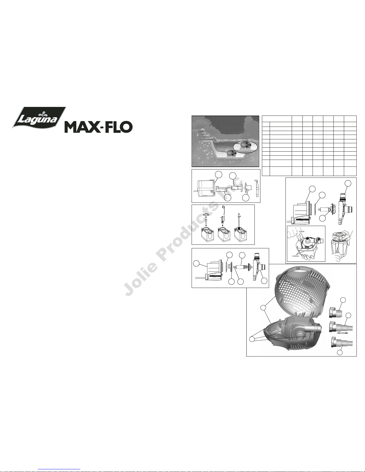
600/2200 900/3500 1500/6000 2000/7500 2400/9000 2900/11000
PT-340 PT-342 PT-344 PT-346 PT-348 PT-350
1 Motor PT-382 PT-384 PT-388 PT-390 PT-392 PT-394
2 Seal Ring – PT-762 PT-763 PT-764 PT-764 PT-764
3 Impeller Assembly PT-455 PT-457 PT-459 PT-461 PT-461 PT-465
3A Impeller Shaft PT-759 PT-761 – – – –
4 Impeller Cover PT-737 PT-738 PT-733 PT-735 PT-739 PT-739
5 Impeller Well Cover – PT-768 – – – –
6 Pump Cage PT-439 PT-444 PT-445 PT-446 PT-446 PT-446
7 Pivot Pin Fasteners PT-447 PT-447 PT-447 PT-447 PT-447 PT-447
8 Click-Fit Coupling (1-1/2”) – – – PT-638 PT-638 PT-638
9 Universal Coupling – – – PT-640 PT-640 PT-640
(3/4”, 1”,1-1/4”)
10 Universal Coupling PT-636 PT-636 PT-636 – – –
(3/4”, 1”,1-1/4” Adapter
with 1” Click Fit)
REPLACEMENT PARTS
6
7
9
8
10
Fig.4
WATERFALL
2
3
4
1500/6000
2000/7500
2400/9000
2900/11000
1
Fig.3
English Instructions..................................................................................................................2
Instructions en français............................................................................................................6
Gebrauchsanleitung deutsch ................................................................................................10
Instrucciones en español .......................................................................................................14
Winterizing the Pump
Préparation de la pompe pour l’hiver
So machen Sie Ihre Pumpe winterfest
Acondicionamiento para el invierno de la bomba ..............................................................18
Warranty Card
Fiche de garantie
Garantie-Registrierungskarte ..........................................................................................19-20
21
Fig.1
1
3A
3
4
600/2200
900/3500
2
5 3A
3
4
1
Fig.2
To remove Impeller Shaft,
use tool provided.
Fig.1A
Jolie Products Inc

Cleaning the Pump Cage
The main purpose of the Pump Cage is to keep the pump free of bigger solid particles (or solids) that could potentially clog the pump
motor. It is therefore normal that these solids progressively accumulate on the external surface of the cage and, with the passing of
time, can diminish the performance of the pump, as evidenced by
less water flow to the filter or waterfall. To clean the cage and
restore the pump performance to its original level, proceed with one
of the following:
• Without removing the pump from the pond, brush off the debris
from the external surface of the cage using a broom or similar
tool. For best results,brush the cage along the ribs
• Remove the pump cage from the pond, unlock the pivot pin
fasteners (Fig. 6) and remove the upper half of the cage. Clean all
components with streaming water from a garden hose.
Reassemble all components with care
Ensure that the pump cage is securely locked and the
electrical cord is seated properly in position before lifting or
operating the pump (see
Closing the Pump Cage
).
Cleaning the pump motor impeller, impeller
well, and impeller cover
CAUTION: The pump motor includes a high quality ceramic
shaft that provides long-lasting, reliable performance when
properly maintained. However, extreme care should be taken
when handling the shaft during maintenance. Avoid dropping
or pressing too hard on it to avoid breakage or hairline fractures, which may cause the shaft to snap while in operation.
Take the pump out of the pond, unlock the pivot pin fasteners and
remove the upper half of the cage. Free the pump from the lower
half of the cage.
Proceed with the following cleaning instructions as per pump model:
Max-Flo 600/2200 (Fig. 1 + 1A)
1) Remove the motor cover, then remove the impeller cover (4) by
twisting and pulling it off.
2) Remove the impeller assembly (3)
3) If necessary, remove the impeller shaft (3A) using the tool pro-
vided (A-17015) (Fig. 1A)
4) Clean all components in clean water only, using a small, non-
abrasive brush, if necessary.DO NOT USE DETERGENTS OR
OTHER CHEMICAL CLEANERS which could damage the pump
and pollute the pond.
5) Reassemble all components with care (see
Closing the Pump
Cage
).
Max-Flo 900/3500 (Fig. 2)
1) Using a Phillips (cross-headed) screwdriver, unscrew the four
screws on the impeller cover (4) and remove it
2) Remove the impeller assembly (3)
3) Clean all components in clean water only, using a small, non-
abrasive brush, if necessary. DO NOT USE DETERGENTS OR
OTHER CHEMICAL CLEANERS which could damage the pump
and pollute the pond
4) Reassemble all components with care (see
Closing the Pump Cage
).
Max-Flo
1500/6000 (Fig. 3)
1) Using a Phillips (cross-headed) screwdriver, unscrew the three
screws on the impeller cover (4) and remove it
2) Remove the impeller assembly (3) by grasping the flange. This
operation will cause the Seal Ring (2) to come out of its seat
3) Clean all components in clean water only, using a small,
non-abrasive brush, if necessary. DO NOT USE DETERGENTS OR
OTHER CHEMICAL CLEANERS which could damage the pump
and pollute the pond
4) Reassemble all components with care (see
Closing the Pump
Cage
), by first placing the impeller assembly and then the Seal
Ring on their proper seats. Ensure that the impeller bearing,
bushing and O-Ring are correctly placed at the bottom of the
impeller well.
WARNING: Always unplug or disconnect all appliances in the
pond from the electrical supply before installing, repairing,
maintaining or handling the equipment in the water.
IMPORTANT: To achieve the best pump operation, always use
the largest bore hose possible. Avoid sharp bends in the
hosing; gradual curves are preferred.
Installation:
WARNING: Do not plug in the pump before it is correctly and
fully installed.
1) Connect a flexible hose (not included) to the "Click-Fit" coupling
provided. If using a Universal "Click-Fit" coupling (PT-640), cut
the coupling at the required size by using a small hack saw in
order to allow the hose to fit properly and to achieve the best
water flow
2) Insert the coupling, complete with hose attached, onto the outlet
of the pump
3) Place the pump in the pond ensuring that is completely
immersed in water and securely installed on a solid, level and
elevated platform. If necessary, use the keyhole-shaped slots at
the bottom of the pump to fasten it to a secure base.
4) Connect the other end of the hose to a filter or waterfall (not
included) according to your requirements
Opening and Closing the Pump Cage (see Fig. 6)
The upper and lower halves of the
pump cage are fastened together by
pivot pin fasteners. Using a standard
flat screwdriver (5 mm to 8 mm), do
the following:
To open the pump cage: Gently turn
the fastener counterclockwise by 1/4
to release the pin.
To close the pump cage: Gently
press on the fastener and turn clockwise by 1/4 to lock the pin.
Pump Operation
Once the pump is fully installed, it can be started by inserting the
plug in the electrical receptacle/socket.
Pump Maintenance
WARNING: Always unplug or disconnect all appliances in the
pond from the electrical supply before installing, repairing,
maintaining or handling the equipment in the water.
To avoid shortening the life of the pump, follow these simple
maintenance procedures:
• Once a week, verify that the pump performance is satisfactory. If
you detect a drop in pump performance (such as a decrease in
water flow from the pump or to the waterfall) first clean the Pump
Cage and the hosing. If the water flow is still not fully restored to
its original performance, clean the Impeller, Impeller Well and
Impeller Cover (See maintenance procedure below)
• The Pump Cage must be cleaned at least once a month
• When necessary, or at least once a year, clean the pump motor
completely (Impeller, Impeller Well, and Impeller Cover) and check
that no limestone deposits, which could jeopardize pump operation, are present
• To keep the pump in good working order, always replace any worn
parts
• The pump motor has no user serviceable parts. If the motor or the
electrical cord is damaged, discard the pump
• If you have any doubts, consult your Laguna retailer or call the
appropriate customer service department listed at the back of this
manual
Fig.6
Waterfall and Filter Pump
For freshwater and submersible use only
Read thoroughly prior to installation and operation
IMPORTANT SAFETY INSTRUCTIONS
WARNING: To guard against injury, basic safety precautions should be observed, including the following:
1.
READ AND FOLLOW ALL SAFETY INSTRUCTIONS
And all the important notices on the appliance before using the
pump. Failure to do so may result in loss of fish life and/or
damage to this appliance.
2. DANGER – To avoid possible electric shock, special care should
be taken since water is employed in the use of pond equipment.
For each of the following situations, do not attempt repairs
yourself; return the appliance to the store where it was purchased if still under warranty.
A. If the appliance shows any sign of abnormal water leakage or if
RCD (or GFCI- Ground Fault Current Interrupter) switches off,
disconnect the power supply cord from mains (main power
supply) and remove pump from water.
B. Carefully examine the appliance after installation. It should not
be plugged if there is water on parts not intended to be wet.
C. Do not operate any appliance if it has a damaged cord or plug,
or if it is malfunctioning or if it is dropped or damaged in any
manner.The power cord of this appliance cannot be replaced; if
the cord is damaged, the appliance should be discarded. Never
cut the cord.
3. Close supervision is necessary when any appliance is used by or
near children.
4. To avoid injury, do not touch moving parts or hot parts.
5. CAUTION – Always unplug or disconnect all appliances in the
pond from the electrical supply before placing hands in water,
before putting on or taking off parts and while the equipment is
being installed, maintained or handled. When inserting or
removing the pump from the water, always pull out the main
electrical plug. Never yank the cord to pull the plug from outlet.
Grasp the plug and pull to disconnect. Always unplug an
appliance from an outlet when not in use. Never lift the Pump by
the cord. Use the unit handle.
6. CAUTION – This is a pond pump. This Pump Has Been Evaluated
for Use With Water Only. Do not use this pump for other than
intended use (i.e.: do not use in swimming pools, bathrooms, etc.).
The use of attachments not recommended or sold by the appliance
manufacturer may cause an unsafe condition.
• Do not use this pump in swimming pools or other situations
where people are immersed;
• This pump is suitable for use in water temperatures up to 35 °C;
• Do not use this pump with inflammable or drinkable liquids.
7. Do not install or store the appliance where it will be exposed the
weather or to temperatures below freezing. Remove and store
the pump in a sheltered place. Shelter pump also from direct
sunlight. The materials have high stability to sunlight but direct
rays may overheat the motor and speed up insulator aging.
8. IMPORTANT - This pump can be operated only when the pump
unit is correctly closed inside its Cage and after checking that
the Cage is securely locked by the fastening screws located on
the unit handle. Make sure that the pump is securely installed
before operating it. Do not allow the pump to run dry.The pump
must be immersed in water completely. This pump must never
operate outside of water.
9. If an extension cord is necessary, ensure connection is watertight
and dust proof.A cord with proper rating should be used. A cord
rated for less amperes or watts than the appliance rating may
overheat. Care should be taken to arrange the cord so that it will
not be tripped over or pulled. The connection should be carried
out by a qualified electrical installer.
10. IMPORTANT – Supply through a Residual Current Device (RCD or
Ground Fault Current Interrupter) with rated residual current not
exceeding 30 mA.
11. WARNING – Risk of electric shock – This pump is supplied with
a grounding-type attachment plug. To reduce the risk of electric
shock:
• be certain that it is connected only to a properly grounded,
grounding-type receptacle
• Use only on portable self-contained fountains no larger than
5 feet in any dimension (FOR U.S.A.ONLY)
SAVE THESE INSTRUCTIONS FOR FUTURE REFERENCE
Only the faithful observation of these installation, electrical and
maintenance guidelines will ensure the safe and efficient use of
this pump.
PUMP INSTALLATION INSTRUCTIONS
General Information
Because of their ability to process water moderately loaded with
suspended solid particles (or solids), the Waterfall and Filter Pumps
are ideal for use with filtration systems and for creating waterfalls
and watercourses. The pumps are designed to transport suspended
solids to suitable external filter systems (including pressurized filters) which then trap any debris that could potentially pollute pond
water, effectively filtering the pond. The pumps are not suitable for
supplying water to fountainheads, because the fountainhead jets
could easily become clogged by solids processed by the pumps.
The pump motor sits inside a uniquely-shaped cage that is
designed to allow the passage of solids up to a determined size
only (from 6 mm to 8 mm depending on the model), as bigger
solids may clog and damage the pump. The pump must never be
used without its cage.
For improved operation, place the pump in the deepest part of the
pond. At minimum, it must be placed at a depth of 8 inches or 20
cm. If necessary,you can secure the pump to a fixed base by using
the keyhole-shaped slots, located at the bottom of the cage, which
are shaped to allow the fast engaging/disengaging of the pump
from the base. (Fig.5)
Check that the information on the
nameplate (which is located on the
pump) corresponds to the power
supply.The electrical installation and
wiring must comply with the safety
standards in your area. If unsure, ask
a qualified electrician to do the
wiring. The electrical cord must be
protected against any objects that
may potentially damage it. The electrical receptacle/socket must be
located in a dry,protected and easily accessible place.
ADDITIONAL INSTRUCTIONS FOR U.K. ONLY
This product is designed to be permanently wired to the mains
supply in a dry weatherproof enclosure through a double pole
switched fused spur which complies to BS3676, fitted with a 3
Amp fuse. The installation must conform to the regulations of the
Local Electricity Authority which could include the use of plastic or
metal conduit to protect the cable. A 30 mA Residual Current
Device ‘RCD’ must be fitted to the mains supply.
WARNING - THIS APPLIANCE MUST BE EARTHED.
IMPORTANT - The wires in this mains lead are coloured in
accordance with the following code:
Brown - Live Blue - Neutral Green/Yellow - Earth
The Brown lead should be connected to the Live terminal, which
may be marked with an ‘L’ or coloured brown or red.
The Blue lead should be connected to the Neutral terminal, which
may be marked with an ‘N’ or coloured blue or black.
The Green/Yellow lead should be connected to the Earth terminal,
which may be marked with an ‘E’ or coloured green or yellow.
Fig.5
43
Jolie Products Inc

Max-Flo 2000/7500, 2400/9000, and 2900/11000 (Fig.3)
1) Using a Phillips (cross-headed) screwdriver, unscrew the four
screws on the impeller cover (4) and remove it
2) Using a flathead screwdriver, carefully lift out the impeller
assembly.
3) Clean all components in clean water only, using a small, nonabrasive brush, if necessary. DO NOT USE DETERGENTS OR
OTHER CHEMICAL CLEANERS which could damage the pump
and pollute the pond
4) Reassemble all components with care (see
Closing the Pump
Cage
), ensuring that the impeller bearing, bushing and O-Ring
are correctly placed at the bottom of the impeller well.
Replacing the Bushing and O-Ring
(Replacement pack not included. Part # PT-466).
For Max-Flo
1500/6000,
2000/7500, 2400/9000 and
2900/11000 only
Though the bushing is made of very resistant material, it is prone to
wearing in certain conditions. For this reason, it is recommended
that you replace it whenever the impeller unit is replaced. Follow the
instructions provided with the replacement parts package. Once you
have replaced the Bushing and O-Ring, reassemble all parts with
care (see Fig. 3 &
Closing the Pump Cage
).
Volts 120 230-240 120 230-240 120 230-240 120 230-240 120 230-240 120 230-240
Hertz 60 50 60 50 60 50 60 50 60 50 60 50
Watts 32 32 65 55 100 80 100 100 100 100 130 125
Maximum depth 6’6”/2 m 6’6”/2 m 6’6”/2 m 6’6”/2 m 6’6”/2 m 6’6”/2 m
Max flow rate
Max head
Degree of protection IPX8 IPX8 IPX8 IPX8 IPX8 IPX8
MAX-FLO PUMP 600/
2200
900/
3500 1500/6000 2000/7500 2400/9000 2900/11000
PT-340 PT-342 PT-344 PT-346 PT-348 PT-350
US GPH
LPH
ft
m
899
3400
6’4”
1.95
977
3700
6’2”
1.9
582
2200
5’10”
1.8
582
2200
5’10”
1.8
11’6”
3.50
1585
6000
13’5”
4.10
1558
5900
12’2”
3.7
1981
7500
12’2”
3.7
1981
7500
12’2”
3.7
2378
9000
12’2”
3.7
2378
9000
14’9”
4.5
2853
10800
14’9”
4.5
2800
10600
Closing the Pump Cage
Place the pump inside the bottom half of the cage. Ensure that the
electrical cord is properly seated inside the recess located on the
bottom half of the cage.
At a 45° angle, join the top half of the cage to the bottom half of
the cage by first aligning the two posts, located on the top half of
the cage, with the two docking holes, located at the bottom half of
the cage. Close the cage completely, ensuring that both halves are
fully aligned. Lock the pivot pin fasteners as explained in
section called
Opening and Closing the Pump Cage
.
Ensure that the pump cage is securely locked and the electrical cord
is seated properly in position before lifting or operating the pump.
TROUBLESHOOTING
LOW FLOW FROM PUMP
• Check that the pump cage is clean
• Check the hose for blockages
• Check that the pump is free of dirt and debris
NO FLOW FROM PUMP
• Check that the power supply is on
• Check the fuse (UK market only) and wiring
• Check that the plug is correctly connected to the electrical
receptacle/socket
• Check that the pump cage is clean
• Check the hose for blockages
• Check that the pump is free of dirt and debris
• Check that the pump is completely immersed in water
WARRANTY
The Pumps are guaranteed against defects in material or
workmanship for a period of 3 years from date of purchase,
under normal usage. PowerJet Pumps will be repaired or
replaced at manufacturer’s discretion, free of charge. This
warranty does not apply to any PowerJet Pump which has
been subjected to misuse, negligence,tampering or accidental
damage to the impeller or impeller shaft. No liability is
assumed with respect to loss or damage to livestock or
personal property irrespective of the cause thereof. This
warranty does not affect your statutory rights. Failure caused
by misuse is not covered by this warranty.
65
CASCADE
ABC
D
G
H
F
E
600/2200 900/3500 1500/6000 2000/7500 2400/9000 2900/11000
PT-340 PT-342 PT-344 PT-346 PT-348 PT-350
1 Moteur PT-382 PT-384 PT-388 PT-390 PT-392 PT-394
2 Joint d’étanchéité – PT-762 PT-763 PT-764 PT-764 PT-764
3 Couronne PT-455 PT-457 PT-459 PT-461 PT-461 PT-465
3A Arbre de la couronne PT-759 PT-761 – – – –
4 Couvercle de la couronne PT-737 PT-738 PT-733 PT-735 PT-739 PT-739
5
Couvercle du puits de la couronne
– PT-768 – – – –
6 Boîtier de la pompe PT-439 PT-444 PT-445 PT-446 PT-446 PT-446
7 Axes d’articulation PT-447 PT-447 PT-447 PT-447 PT-447 PT-447
8
Raccord auto-bloquant (38 mm)
– – – PT-638 PT-638 PT-638
9 Raccord universel – – – PT-640 PT-640 PT-640
(19, 25,32 mm)
10
Accouplement rigide universel
PT-636 PT-636 PT-636 – – –
(19,25, 32 mm avec adapteur pour
raccord auto-bloquant de25 mm
PIÈCES DE RECHANGE
6
7
9
8
10
Fig.4
2
3
4
1500/6000
2000/7500
2400/9000
2900/11000
1
Fig.3
Fig.1
1
3A
3
4
600/2200
900/3500
2
5 3A
3
4
1
Fig.2
Pour retirer l’arbre de la
couronne,utiliser l’outil fourni.
Fig.1A
VIS
VIS
Jolie Products Inc
 Loading...