

laguna Max-Flo 16000, Max-Flo 4200 Installation And Maintenance Manual

4200
230-240V 50Hz
120V 60Hz
Installation and
Maintenance Guide
READ THOROUGHLY BEFORE ATTEMPTING INSTALLATION AND KEEP
FOR FUTURE REFERENCE
Einbau- und
Wartungsanleitung
SORGFÄLTIG VOR BEGINN DER INSTALLATION DURCHLESEN UND FÜR SPÄTERE
VERWENDUNG AUFBEWAHREN
Notice d’installation et
d’entretien
LIRE SOIGNEUSEMENT AVANT D’ENTREPRENDRE L’INSTALLATION DE L’APPAREIL.
CONSERVER CETTE NOTICE POUR RÉFÉRENCES ULTÉRIEURES.
Guía de instalación y
mantenimiento
LEA ATENTAMENTE ESTE FOLLETO ANTES DE INTENTAR
LA INSTALACIÓN Y GUARDE ESTAS INSTRUCCIONES
PARA REFERENCIA FUTURA
Template for mounting the pump
to a fixed base
The pump has two keyhole-shaped slots at the bottom of the cage that allow you to
fasten the pump to a fixed base using the screws and, if necessary,the plug anchors
(for cement bases) provided.
Use this template to determine the exact position of the screws on the fixed base.
Note that the base must be elevated, solid,and secure.
Modèle pour le montage de la pompe à une
base fixe
La pompe est munie de deux ouvertures en forme de trous de serrure situées sous le
boîtier vous permettant d’attacher la pompe à une base fixe à l’aide des vis, et si
nécessaire,à l’aide des ancrages (pour base de ciment) qui sont fournis.
Utiliser ce modèle pour déterminer la position exacte des vis sur la base fixe. Noter
que la base doit être élevée,solide et stable.
Schablone zur Montage der Pumpe auf
einem fest montierten Sockel
Die Pumpe weist am Korbboden zwei schlüssellochförmige Schlitze auf,die es Ihnen
gestatten, sie mittels der mitgelieferten Schrauben bzw.Dübel (für Zementsockel) auf
einem fest montierten Sockel anzubringen.
Verwenden Sie diese Schablone,um die genaue Position der Schrauben auf dem fest
montierten Sockel zu bestimmen. Beachten Sie, dass der Sockel erhöht liegen und
solide und sicher montiert sein muss.
Plantilla para montar la bomba a una base
fija
La bomba tiene dos ranuras tipo ojo de cerradura en la parte inferior de la caja que
permiten sujetar la bomba a una base fija usando los tornillos y, si fuera necesario,
los sujetadores del enchufe (para las bases de cemento) provistos.
Utilice esta plantilla para determinar la posición exacta de los tornillos con respecto
a la base fija. Cerciórese de que la base esté elevada,sólida y segura.
✁
16000
MAX FLO 4200US-16000EU.qxd 10/24/06 10:02 AM Page 1
Waterfall and Filter Pump
For freshwater and submersible use only
Read thoroughly prior to installation and operation
IMPORTANT SAFETY INSTRUCTIONS
WARNING: To guard against injury, basic safety precautions should be observed, including the following:
1.
READ AND FOLLOW ALL SAFETY INSTRUCTIONS
And all the important notices on the appliance before using the
pump. Failure to do so may result in loss of fish life and/or
damage to this appliance.
2. DANGER – To avoid possible electric shock, special care should
be taken since water is employed in the use of pond equipment.
For each of the following situations, do not attempt repairs
yourself; return the appliance to the store where it was purchased if still under warranty.
A. If the appliance shows any sign of abnormal water leakage or if
RCD (or GFCI- Ground Fault Current Interrupter) switches off,
disconnect the power supply cord from mains (main power
supply) and remove pump from water.
B. Carefully examine the appliance after installation. It should not
be plugged if there is water on parts not intended to be wet.
C. Do not operate any appliance if it has a damaged cord or plug,
or if it is malfunctioning or if it is dropped or damaged in any
manner.The power cord of this appliance cannot be replaced; if
the cord is damaged, the appliance should be discarded. Never
cut the cord.
3. Close supervision is necessary when any appliance is used by or
near children.
4. To avoid injury, do not touch moving parts or hot parts.
5. CAUTION – Always unplug or disconnect all appliances in the
pond from the electrical supply before placing hands in water,
before putting on or taking off parts and while the equipment is
being installed, maintained or handled. When inserting or
removing the pump from the water, always pull out the main
electrical plug. Never yank the cord to pull the plug from outlet.
Grasp the plug and pull to disconnect. Always unplug an
appliance from an outlet when not in use. Never lift the Pump by
the cord. Use the unit handle.
6. CAUTION – This is a pond pump.This pump has been evaluated for
use with water only. Do not use this pump for other than intended
use (i.e.: do not use in swimming pools,bathrooms, etc.). The use of
attachments not recommended or sold by the appliance
manufacturer may cause an unsafe condition.
• Do not use this pump in swimming pools or other situations
where people are immersed;
• This pump is suitable for use in water temperatures up to 35 °C;
• Do not use this pump with inflammable or drinkable liquids.
7. Do not install or store the appliance where it will be exposed the
weather or to temperatures below freezing. Remove and store
the pump in a sheltered place. Shelter pump also from direct
sunlight. The materials have high stability to sunlight but direct
rays may overheat the motor and speed up insulator aging.
8. IMPORTANT - This pump can be operated only when it is cor-
rectly installed inside its cage and the cage securely locked with
the fastening screws located on the pump handle or outside the
cage with an intake strainer attached to the intake of the pump.
Make sure that the pump is securely installed before operating
it. Do not allow the pump to run dry. The pump must be
immersed in water completely. This pump must never operate
outside of water.
9. If an extension cord is necessary, ensure connection is watertight
and dust proof.A cord with proper rating should be used. A cord
rated for less amperes or watts than the appliance rating may
overheat. Care should be taken to arrange the cord so that it will
not be tripped over or pulled. The connection should be carried
out by a qualified electrical installer.
10. IMPORTANT – Supply through a Residual Current Device (RCD or
Ground Fault Current Interrupter) with rated residual current not
exceeding 30 mA.
11. WARNING – Risk of electric shock – This pump is supplied with a
grounding-type attachment plug. To reduce the risk of electric
shock:
• be certain that it is connected only to a properly grounded,
grounding-type receptacle
• Use only on portable self-contained fountains no larger than 5
feet in any dimension (FOR U.S.A.ONLY)
SAVE THESE INSTRUCTIONS FOR FUTURE REFERENCE
Only the faithful observation of these installation, electrical and
maintenance guidelines will ensure the safe and efficient use of this
pump.
PUMP INSTALLATION INSTRUCTIONS
General Information
Because of its ability to process water moderately loaded with suspended solid particles (or solids), this Waterfall and Filter Pump is
ideal for use with filtration systems and for creating waterfalls and
watercourses.The pump is designed to transport suspended solids to
suitable external filter systems (including pressurized filters) which
then trap any debris that could potentially pollute pond water,effectively filtering the pond. The pump is not suitable for supplying
water to fountainheads, because the fountainhead jets could easily
become clogged by solids processed by the pumps.
The pump motor sits inside a uniquely-shaped cage that is designed
to allow the passage of solids up to a determined size of 3/8” (10
mm). Bigger solids may clog and damage the pump.
For the 230-240 V/50 Hz version (Max-Flo 16000): The pump
must never be used without its cage.
For the 120 V/60 Hz version (Max-Flo 4200):The pump is sold
with an add-on intake strainer which can be connected to the
input of the pump, in the event that you want to use the
pump without its cage in instances where space is limited,
such as in the chamber of a skimmer filter.
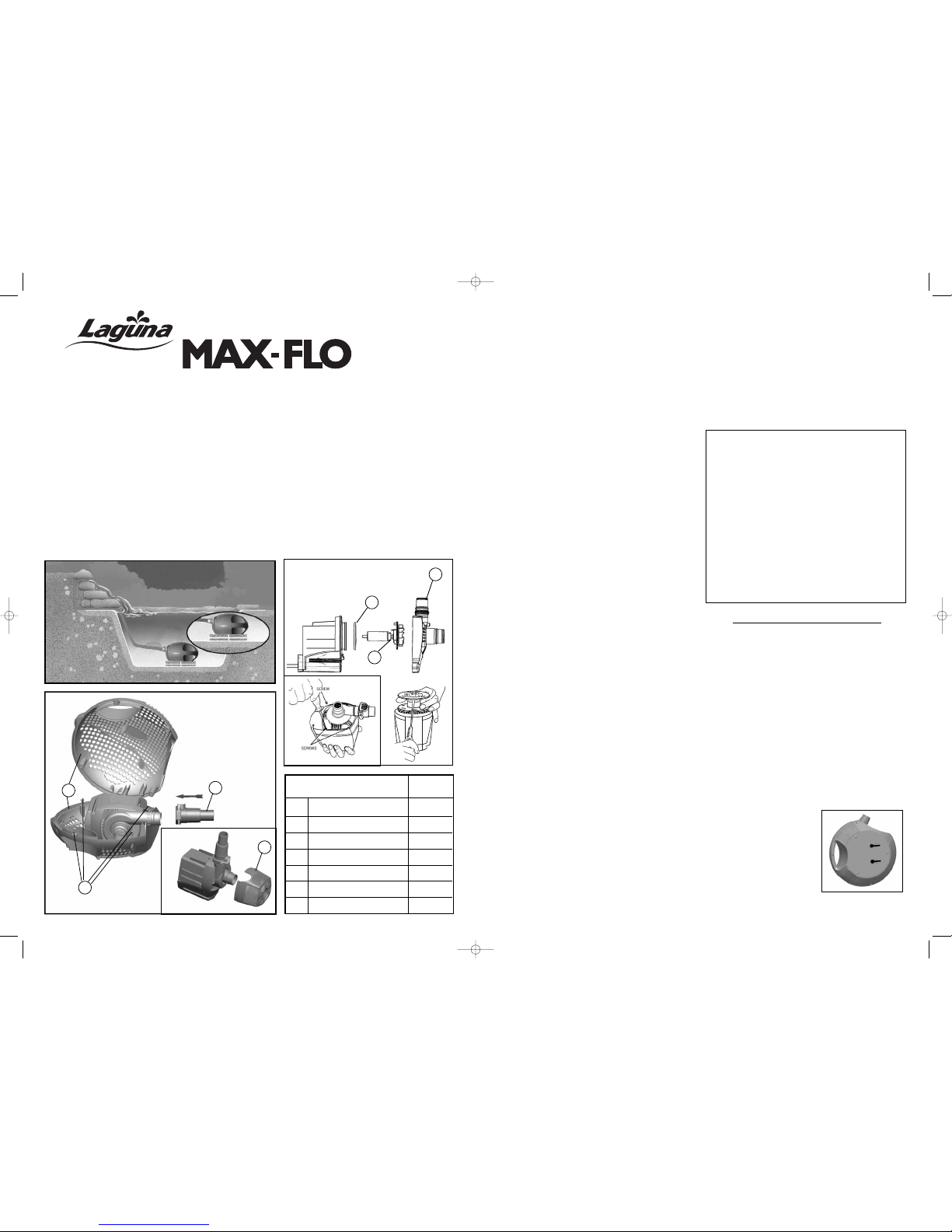
For improved operation, place the
pump in the deepest part of the
pond. At minimum,it must be placed
at a depth of 8 inches or 20 cm. If
necessary, you can secure the pump
to a fixed base by using the keyholeshaped slots, located at the bottom
of the cage, which are shaped to
allow the fast engaging/disengaging
of the pump from the base. (Fig.2)
Check that the information on the nameplate (which is located on
the pump) corresponds to the power supply.
ADDITIONAL INSTRUCTIONS FOR U.K. ONLY
This product is designed to be permanently wired to the mains
supply in a dry weatherproof enclosure through a double pole
switched fused spur which complies to BS3676, fitted with a 3
Amp fuse. The installation must conform to the regulations of the
Local Electricity Authority which could include the use of plastic or
metal conduit to protect the cable. A 30 mA Residual Current
Device ‘RCD’ must be fitted to the mains supply.
WARNING - THIS APPLIANCE MUST BE EARTHED.
IMPORTANT - The wires in this mains lead are coloured in
accordance with the following code:
Brown - Live Blue - Neutral Green/Yellow - Earth
The Brown lead should be connected to the Live terminal, which
may be marked with an ‘L’ or coloured brown or red.
The Blue lead should be connected to the Neutral terminal, which
may be marked with an ‘N’ or coloured blue or black.
The Green/Yellow lead should be connected to the Earth terminal,
which may be marked with an ‘E’ or coloured green or yellow.
4200/16000
PT-352
1 Seal Ring PT-764
2 Impeller Assembly PT-354
3 Impeller Cover PT-355
4 Pump Cage PT-356
5 Pivot Pin Fasteners PT-447
61-
1/4
- 1-
1/2
Click-Fit Coupling PT-358
7 Intake Strainer PT-357
MAX FLO 4200 ONLY
REPLACEMENT PARTS
4
5
Fig.1a
Fig.1
WATERFALL
English Instructions..........................................................................................................................................1
Instructions en français ...................................................................................................................................5
Gebrauchsanleitung auf Deutsch ...................................................................................................................9
Instrucciones en español ...............................................................................................................................13
Winterizing the Pump
Préparation de la pompe pour l’hiver
So machen Sie Ihre Pumpe winterfest
Acondicionamiento de la bomba para el invierno......................................................................................17
Warranty Card
Fiche de garantie
Garantie-Registrierungskarte
Tarjeta de Registro de Garantía ..............................................................................................................10-19
21
6
1
3
2
7
Fig.2
MAX FLO 4200US-16000EU.qxd 10/24/06 10:02 AM Page 3
have replaced the Bushing and O-Ring, reassemble all parts with
care (see Fig.1 &
Closing the Pump Cage
).
Closing the Pump Cage
Place the pump inside the bottom half of the cage. Ensure that the
electrical cord is properly seated inside the recess located on the
bottom half of the cage.
At a 45° angle, join the top half of the cage to the bottom half of
the cage by first aligning the two posts, located on the top half of
the cage, with the two docking holes, located at the bottom half of
the cage. Close the cage completely, ensuring that both halves are
fully aligned. Lock the pivot pin fasteners as explained in
section called
Opening and Closing the Pump Cage
.
Ensure that the pump cage is securely locked and the electrical cord
is seated properly in position before lifting or operating the pump.
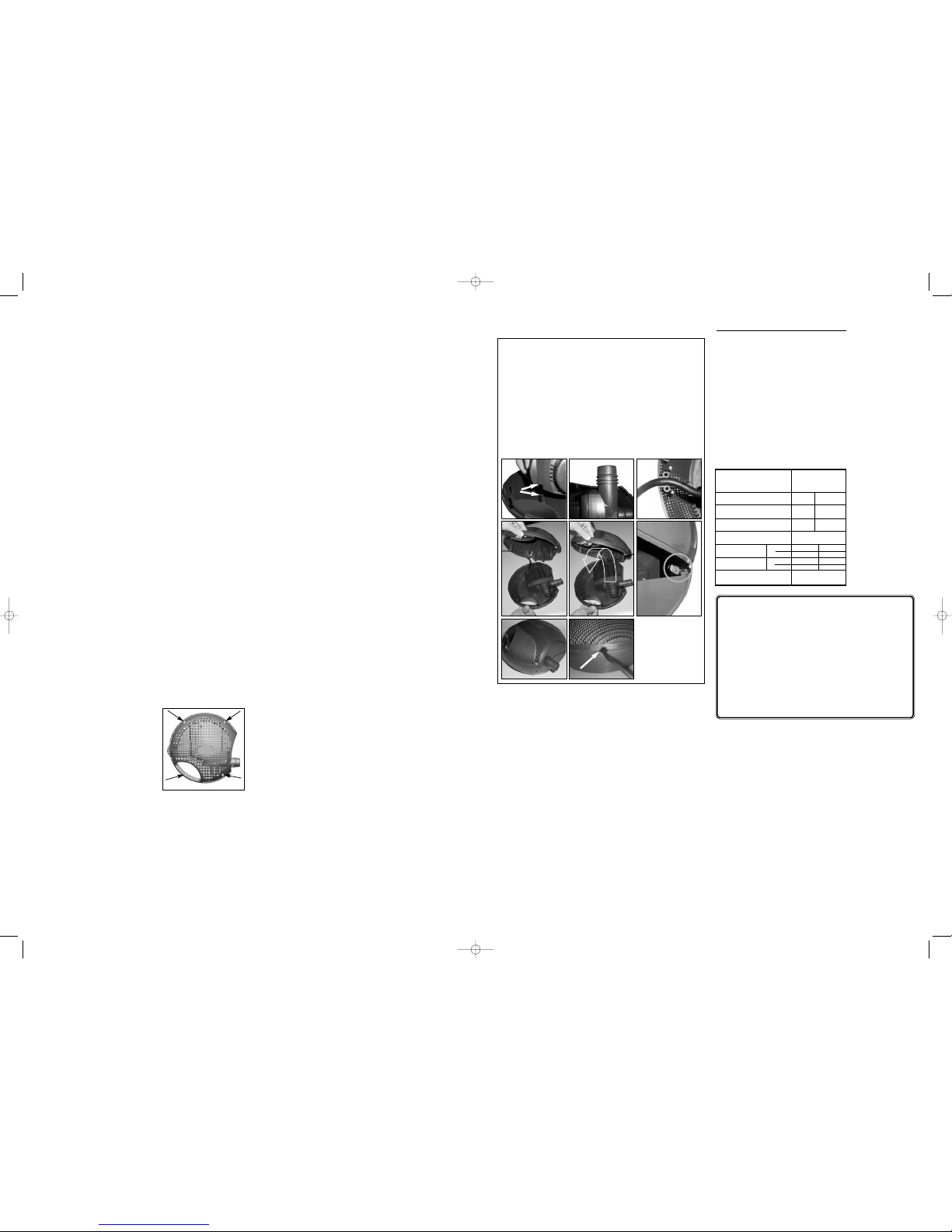
Volts 120 230-240
Hertz 60 50
Watts 160 160
Maximum depth 6’6”/2 m
Max flow rate
Max head
Degree of protection IPX8
MAX-FLO PUMP 4200/16
000
PT-352
US GPH
LPH
ft
m
4200
16000
14’9”
4.5
4200
16000
14’9”
4.5
TROUBLESHOOTING
LOW FLOW FROM PUMP
• Check that the pump cage is clean
• Check the hose for blockages
• Check that the pump is free of dirt and debris
NO FLOW FROM PUMP
• Check that the power supply is on
• Check the fuse (UK market only) and wiring
• Check that the plug is correctly connected to the electrical
receptacle/socket
• Check that the pump cage is clean
• Check the hose for blockages
• Check that the pump is free of dirt and debris
• Check that the pump is completely immersed in water
WARRANTY
The pump is guaranteed against defects in material or
workmanship for a period of 3 years from date of purchase,
under normal usage. The pump will be repaired or replaced at
manufacturer’s discretion, free of charge. This warranty does
not apply to any pump that has been subjected to misuse,
negligence, tampering or accidental damage to the impeller or
impeller shaft. No liability is assumed with respect to loss or
damage to livestock or personal property irrespective of the
cause thereof. This warranty does not affect your statutory
rights. Failure caused by misuse is not covered by this warranty.
ABC
D
G
H
F
E
• Once a week, verify that the pump performance is satisfactory. If
you detect a drop in pump performance (such as a decrease in
water flow from the pump or to the waterfall) first clean the Pump
Cage and the hosing. If the water flow is still not fully restored to
its original performance, clean the Impeller, Impeller Well and
Impeller Cover (
Cleaning the pump motor impeller, impeller
well, and impeller cover
)
• The Pump Cage must be cleaned at least once a month
• When necessary, or at least once a year, clean the pump motor
completely (Impeller,Impeller Well, and Impeller Cover) and check that
no limestone deposits, which could jeopardize pump operation, are
present
• To keep the pump in good working order, always replace any worn
parts
• The pump motor has no user serviceable parts. If the motor or the
electrical cord is damaged, discard the pump
• If you have any doubts,consult your Laguna retailer or call the appropriate customer service department listed at the back of this manual
Cleaning the Pump Cage
The main purpose of the Pump Cage is to keep the pump free of bigger solid particles (or solids) that could potentially clog the pump
motor. It is therefore normal that these solids progressively accumulate on the external surface of the cage. With the passing of time,
they can diminish the performance of the pump, as evidenced by
less water flow to the filter or waterfall. To clean the cage and
restore the pump performance to its original level, proceed with one
of the following:
• Without removing the pump from the pond, brush off the debris
from the external surface of the cage using a broom or similar
tool. For best results,brush the cage along the ribs
•Remove the pump from the pond, unlock the pivot pin
fasteners (Fig.3) and remove the upper half of the cage. Clean all
components with streaming water from a garden hose.
Reassemble all components with care
Ensure that the pump cage is securely locked and the
electrical cord is seated properly in position before lifting or
operating the pump (see
Closing the Pump Cage
).
Cleaning the pump motor impeller, impeller
well, and impeller cover
CAUTION: The pump motor includes a high quality ceramic
shaft that provides long-lasting, reliable performance when
properly maintained. However, extreme care should be taken
when handling the shaft during maintenance. Avoid dropping
or pressing too hard on it to avoid breakage or hairline fractures, which may cause the shaft to snap while in operation.
Take the pump out of the pond, unlock the pivot pin fasteners and
remove the upper half of the cage. Free the pump from the lower
half of the cage.
1) Using a Phillips (cross-headed) screwdriver, unscrew the four
screws on the impeller cover (4) and remove the impeller cover
2) Using a flathead screwdriver, carefully lift out the impeller
assembly.
3) Clean all components in clean water only, using a small, non-
abrasive brush, if necessary. DO NOT USE DETERGENTS OR
OTHER CHEMICAL CLEANERS which could damage the pump
and pollute the pond
4) Reassemble all components with care (see
Closing the Pump
Cage
), ensuring that the impeller bearing, bushing and O-Ring
are correctly placed at the bottom of the impeller well.
Replacing the Bushing and O-Ring
(Replacement pack not included. Part # PT-466).
Though the bushing is made of very resistant material, it is prone to
wearing in certain conditions. For this reason, it is recommended
that you replace it whenever the impeller unit is replaced. Follow the
instructions provided with the replacement parts package. Once you
The electrical installation and wiring must comply with the safety
standards in your area. If unsure, ask a qualified electrician to do the
wiring. The electrical cord must be protected against any objects
that may potentially damage it. The electrical receptacle/socket must
be located in a dry,protected and easily accessible place.
WARNING: Always unplug or disconnect all appliances in the
pond from the electrical supply before installing, repairing,
maintaining or handling the equipment in the water.
IMPORTANT: To achieve the best pump operation, always use
the largest bore hose possible. Avoid sharp bends in the
hosing; gradual curves are preferred.
Installation:
WARNING: Do not plug in the pump before it is correctly and
fully installed.
1) Connect a flexible hose (not included) to the "Click-Fit" coupling
provided. If necessary cut the coupling at the required size by
using a small hack saw in order to allow the hose to fit properly
and to achieve the best water flow.
2) Insert the coupling, complete with hose attached, onto the outlet
of the pump
3) Place the pump in the pond ensuring that it is completely
immersed in water and securely installed on a solid, level and
elevated platform. If necessary, use the keyhole-shaped slots at
the bottom of the pump to fasten it to a secure base.
4) Connect the other end of the hose to a filter or waterfall (not
included) according to your requirements
Installing the intake strainer
(available with Max-Flo 4200 only)
The pump is sold with an add-on intake strainer that can be connected to the input of the pump, in the event that you want to use it
without its cage in instances where space is
limited, such as in the chamber of a skimmer filter.
1) Remove the pivot pin fasteners as described below in
Opening
and Closing the Pump Cage
.
2) Remove the pump from the cage and attach the intake strainer
over the intake of the pump (See Fig 1a)
3) Connect the hosing as described in the installation procedure
above and install the pump in the desired location, or if necessary, place the pump in the desired location and connect the
hosing to the output of the pump
Do not allow the pump to run dry.
Opening and Closing the Pump Cage (See Fig.3)
The upper and lower halves of the
pump cage are fastened together by
pivot pin fasteners. Using a standard
flat screwdriver (5 mm to 8 mm), do
the following:
To open the pump cage: Gently turn
the fastener counterclockwise by 1/4
to release the pin.
To close the pump cage: Gently
press on the fastener and turn clockwise by 1/4 to lock the pin.
Pump Operation
Once the pump is fully installed, it can be started by inserting the
plug in the electrical receptacle/socket.
Pump Maintenance
WARNING: Always unplug or disconnect all appliances in the
pond from the electrical supply before installing, repairing,
maintaining or handling the equipment in the water.
To avoid shortening the life of the pump, follow these simple
maintenance procedures:
Fig.3
43
MAX FLO 4200US-16000EU.qxd 10/24/06 10:02 AM Page 5

9. Si une rallonge électrique est nécessaire, on doit s’assurer que le
raccord est étanche et antipoussière. Il faut utiliser un cordon
électrique d’un calibre suffisant. Un cordon de moins d’ampères
ou de watts que le calibre de l’appareil peut surchauffer. Le cordon devrait être placé de façon à éviter que quelqu’un trébuche.
Le raccordement devrait être effectué par un électricien qualifié.
10. IMPORTANT – Fournir l’électricité à l’aide d’un disjoncteur différentiel (ou interrupteur de défaut à la terre) ayant un courant
résiduel ne dépassant pas 30 mA.
11. MISE EN GARDE – Risque de choc électrique – Cette pompe est
munie d’une fiche de raccordement de mise à la terre. Afin de
réduire le risque de choc électrique :
• vous assurer qu’elle est branchée seulement à une prise de
courant adéquatement mise à la terre.
CONSERVER CES MESURES DE SÉCURITÉ
POUR CONSULTATION
Seule l’observation rigoureuse de ces directives concernant l’installation, l’électricité et l’entretien assurera l’utilisation sûre et
efficace de cette pompe.
INSTRUCTIONS D’INSTALLATION DE LA POMPE
Information générale
À cause de sa capacité à traiter de l’eau modérément chargée de
particules solides (ou de solides) en suspension, cette pompe filtrante pour cascade est idéale pour les systèmes de filtration et pour
créer des cascades et des cours d’eau. La pompe est conçue pour
transporter des solides en suspension à des filtres extérieurs appropriés (y compris des filtres pressurisés) qui bloquent ensuite les
débris pouvant polluer l’eau du bassin et la filtrent efficacement. La
pompe ne peut fournir l’eau aux jets de fontaine parce que ces
derniers pourraient être bloqués facilement par des solides traités
par les pompes.
Le moteur de la pompe est déposé à l'intérieur d'un boîtier de forme
unique conçu pour laisser passer des solides jusqu'à 10 mm (3/8").
Des solides dépassant cette taille pourraient bloquer et endommager la pompe.
Modèle de 230-240 V/50 Hz (Max-Flo 16000) : la pompe ne
doit jamais être utilisée sans son boîtier.
Modèle de 120 V/60 Hz (Max-Flo 4200) : la pompe est vendue
avec une crépine d'admission additionnelle pouvant être
raccordée à l'entrée d'eau quand on veut l'utiliser sans son
boîtier dans les cas où l'espace est limité, comme dans le
module d'un filtre épurateur.
Pour un meilleur rendement,
déposer la pompe dans la partie la
plus profonde du bassin. Elle doit
être placée à une profondeur d'au
moins 20 cm (8"). Au besoin,il est
possible d’attacher la pompe à une
base fixe en utilisant les ouvertures
en forme de trous de serrure
situées sous le boîtier pour permettre d’installer la pompe rapidement
sur la base et de la dégager également rapidement de la base (Fig. 2).
Vérifier que l’information sur la plaque du fabricant (se trouvant sur
la pompe) correspond à l’alimentation en électricité. L’installation
électrique doit être conforme aux normes de sécurité de votre
secteur. En cas de doute, demander à un électricien qualifié de faire
l’installation électrique. Le cordon d’alimentation doit être protégé
des objets qui peuvent l’endommager. La prise de courant doit être
située dans un endroit sec, protégé et facilement accessible.
Pompe filtrante pour cascade
Utiliser seulement en eau douce et pour submersion
Lire en entier avant l’installation et la mise en marche
MESURES DE SÉCURITÉ
MISE EN GARDE : Pour éviter tout accident, il est important de prendre les précautions suivantes :
1.
LIRE ET SUIVRE TOUTES LES MESURES DE SÉCURITÉ
ainsi que toutes les instructions notées sur l’appareil. Sinon, il
peut en résulter la perte des poissons ou du dommage à cet
appareil.
2. DANGER – Du fait de l’utilisation de l’eau et d’un appareil élec-
trique, une grande prudence est de rigueur avec l’équipement
d’un bassin. Dans chacune des situations suivantes, ne pas
essayer de réparer l’appareil soi-même; le retourner au magasin
où il a été acheté s’il est encore sous garantie.
A. Si l’appareil montre un signe de fuite anormale d’eau ou si le
disjoncteur différentiel (ou disjoncteur de fuite de terre) s’éteint,
débrancher le cordon électrique du réseau d’alimentation
(alimentation principale) et retirer la pompe de l’eau.
B. Examiner soigneusement l’appareil après l’avoir installé. Il ne
devrait pas être branché si de l’eau se trouve sur des pièces ne
devant pas être mouillées.
C. Ne pas faire fonctionner un appareil si son cordon électrique ou sa
fiche sont endommagés, s’il est défectueux, s’il a été échappé ou
endommagé d’une façon quelconque. Le cordon d’alimentation de
cet appareil ne peut être remplacé; s’il est endommagé, l’appareil
doit être jeté. Ne jamais couper le cordon d’alimentation.
3. Il est recommandé de surveiller étroitement les enfants qui
utilisent un appareil ou se trouvent à proximité.
4. Pour éviter les accidents, ne pas toucher aux pièces mobiles ou
chaudes.
5. ATTENTION – Toujours débrancher tous les appareils électriques
dans le bassin avant de placer vos mains dans l’eau, avant
d’installer ou d’enlever des pièces et pendant que l’équipement
est installé, entretenu ou manipulé. Au moment de déposer la
pompe dans l’eau ou de la retirer de l’eau, toujours débrancher
la fiche principale. Ne jamais tirer sur le cordon électrique pour
débrancher l’appareil. Prendre la fiche et débrancher l’appareil.
Toujours débrancher un appareil quand il n’est pas utilisé. Ne
jamais soulever la pompe par le cordon électrique. Utiliser la
poignée de l’appareil.
6. ATTENTION – Il s’agit d’une pompe pour bassin. Cette pompe ne
doit être employée qu’avec de l’eau. Ne pas l'utiliser pour un
emploi autre que celui pour lequel elle a été fabriquée
(par exemple, ne pas s’en servir dans une piscine, une salle de
bain, etc.). L’emploi de fixations ni recommandées ni vendues par
le fabricant de l’appareil peut compromettre sa sécurité.
• Ne pas utiliser cette pompe dans une piscine ou dans d’autres
cas où des personnes sont dans l’eau.
• Cette pompe convient dans de l’eau pouvant atteindre 35 °C.
• Ne pas se servir de cette pompe avec des liquides inflammables
ou potables.
7. Ne pas exposer cet appareil aux intempéries ou à une température en dessous de 0 °C. Retirer et ranger la pompe dans un
endroit couvert. La protéger de la lumière directe du soleil. Les
matériaux ont une stabilité élevée à la lumière du soleil mais les
rayons directs peuvent surchauffer le moteur et accélérer l’usure
de l’isolateur.
8. IMPORTANT - Cette pompe ne peut fonctionner que lorsqu’elle
est bien placée à l’intérieur de son boîtier et que celui-ci est
solidement verrouillé à l'aide des axes d'articulation; ou encore,
elle peut fonctionner en dehors du boîtier si une crépine d'admission est fixée à son entrée d'eau. S’assurer que la pompe est
bien installée avant de la mettre en marche. Ne pas faire fonctionner la pompe à sec. Elle doit être complètement immergée
dans l’eau et ne doit jamais fonctionner en dehors de l’eau.
65
4200/16000
PT-352
1 Bague d'étanchéité PT-764
2 Bloc de la couronne PT-354
3 Couvercle de la couronne PT-355
4 Boîtier de la pompe PT-356
5 Axes d'articulation PT-447
6 PT-358
7 Crépine d'admission PT-357
POMPE MAX-FLO 4200
SEULEMENT
PIÈCES DE RECHANGE
4
5
Fig.1a
Fig.1
CASCADE
6
1
3
2
7
INSTRUCTIONS EN FRANÇAIS
Fig.2
Raccord autobloquant de
32 mm
et
38 mm
(
1-
1/4
" et
1-
1/2
")
VIS
VIS
MAX FLO 4200US-16000EU.qxd 10/24/06 10:02 AM Page 7
 Loading...