

Page 1

G8 Dual Speed
Bench Grinder 230V
Code: 112934
Distributed by
N.B. Some pictures and diagrams in this manual may have buttons and electrical configurations
which differ slightly from the machine you purchased
Version: 3
Date: 15/07/25
DIGITAL MANUAL
Page 2

Contents
Specifications 3
Safety Guidelines 3
Package Contents 9
Key Parts Diagram 10
Assembly & Adjustments 11
General Operations 13
General Maintenance 17
Troubleshooting 18
Parts Diagram and List 19
Parts Table 20
Declaration of Conformity 22
Warranty 23
1
Page 3
Specifications …………………………………………………………………………………..…...3
Safety Guidelines ………………………………………………………………………….…....3-9
Package Contents ……………………………………………………………………………..…..10
Key Parts Diagram …………………………………………………………………………………11
Assembly Instructions ……………………………………………………………………….12-13
Operating Instructions ……………………………………………………………………….14-18
Maintenance …………………………………………………………………………………………18
Troubleshooting ……………………………………………………………………………………19
Parts Diagram and List…………………………………………………………………….…20-21
Power……………………………………………….………...........….......370 w 0 v 50Hz 1Ph
Speed ……………………………………………..…….……Low - 1
Shaft Diameter ………………………….…………………………………........…15.88 mm (5/8”)
Wheel Size ……………………………...….....…200 mm (8”) x 25 mm (1”) x 15.88 mm (5/8”)
Wheel Grit ………………………………………….……………………….……..60 Grit/120 Grit
Wheel Material …………………………………...……………………….White Aluminum Oxide
Weight…………………………………...…………………...............……..............................17 kg
RPM / High - RPM
Read and understand all warnings and operation instructions before using any tool or equipment. Always follow basic
safety precautions to reduce the risk of personal injury. Improper operation, maintenance or modification of tools or
equipment could result in serious injury and property damage. There are certain applications for which tools and
equipment are designed. This product should NOT be modified and/or used for any application other than for which it
was designed.
It is important for you to read and understand this manual. The information it contains relates to protecting your safety
and preventing problems.
This manual contains information that is important for you to know and understand. This information relates to
protecting your safety and preventing equipment problems. To help you recognize this information, we use the
symbols below. Please read the manual and pay attention to these sections
.
injury.
injury.
injury.
or DANGER! Indicates an imminently hazardous situation which, if not avoided, will result in death or serious
or WARNING! Indicatesapotentially hazardous situation which, if not avoided, could result in death or serious
or CAUTION! Indicatesapotentially hazardous situation which, if not avoided, may result
Indicatesahelpful tip from our technical staff.
in minor or moderate
2
Page 4
Read and understand all warnings and operating instructions before using this equipment. Failure to
follow all instructions listed below, may result in electric shock, fire, and/or serious personal injury or property damage.
Woodworking can be dangerous if safe and proper operating procedures are not followed. As with all machinery, there
are certain hazards involved with the operation of the product. Using the machine with respect and caution will
considerably lessen the possibility of personal injury. However, if normal safety precautions are overlooked or ignored,
personal injury to the operator may result. Safety equipment such as guards, push sticks, hold-downs, feather boards,
goggles, dust masks and hearing protection can reduce your potential for injury. But even the best guard won’t make
up for poor judgment, carelessness or inattention. Always use common sense and exercise caution in the workshop. If
a procedure feels dangerous, don’t try it. Figure out an alternative procedure that feels safer. REMEMBER: Your
personal safety is your responsibility.
This machine was designed for certain applications only. We strongly recommend that this machine not
be modified and/or used for any application other than that for which it was designed. If you have any questions
relative to a particular application, do not use the machine until you have first contacted the manufacturer to determine
if it can or should be performed on the product.
If you have any questions relative to its application do not use the product until you have contacted the manufacturer
and we have advised you.
FAILURE TO FOLLOW THESE RULES MAY RESULT IN SERIOUS PERSONAL INJURY.
FOR YOUR OWN SAFETY, READ AND UNDERSTAND THE INSTRUCTION MANUAL BEFORE OPERATING THE MACHINE.
Learn the unit’s application and limitations as well as the specific hazards peculiar to it.
KEEP WORK AREA CLEAN. Cluttered areas and benches invite accidents.
DON’T USE IN DANGEROUS ENVIRONMENT. Don’t use this unit in damp or wet locations or expose it to rain. Keep the work
area well-lighted.
KEEP CHILDREN AND VISITORS AWAY. All children and visitors should be kept a safe distance from the work area.
DISCONNECT UNIT before servicing.
CHECK DAMAGED PARTS. Before further use of the unit, properly repair or replace any part that is damaged.
DISCONNECT UNIT before servicing.
CHECK DAMAGED PARTS. Before further use of the unit, properly repair or replace any part that is damaged.
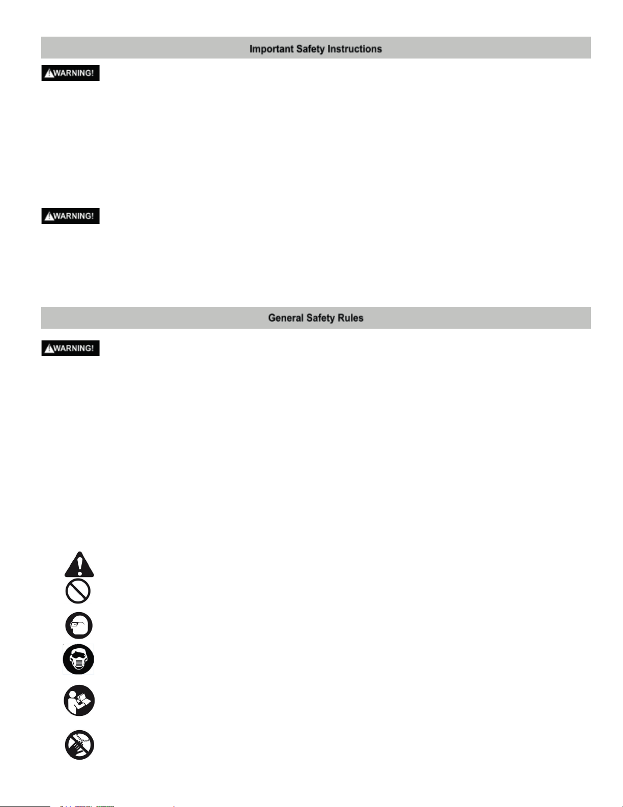
SAFETY ALERT: Precautions that involve your safety
PROHIBITION
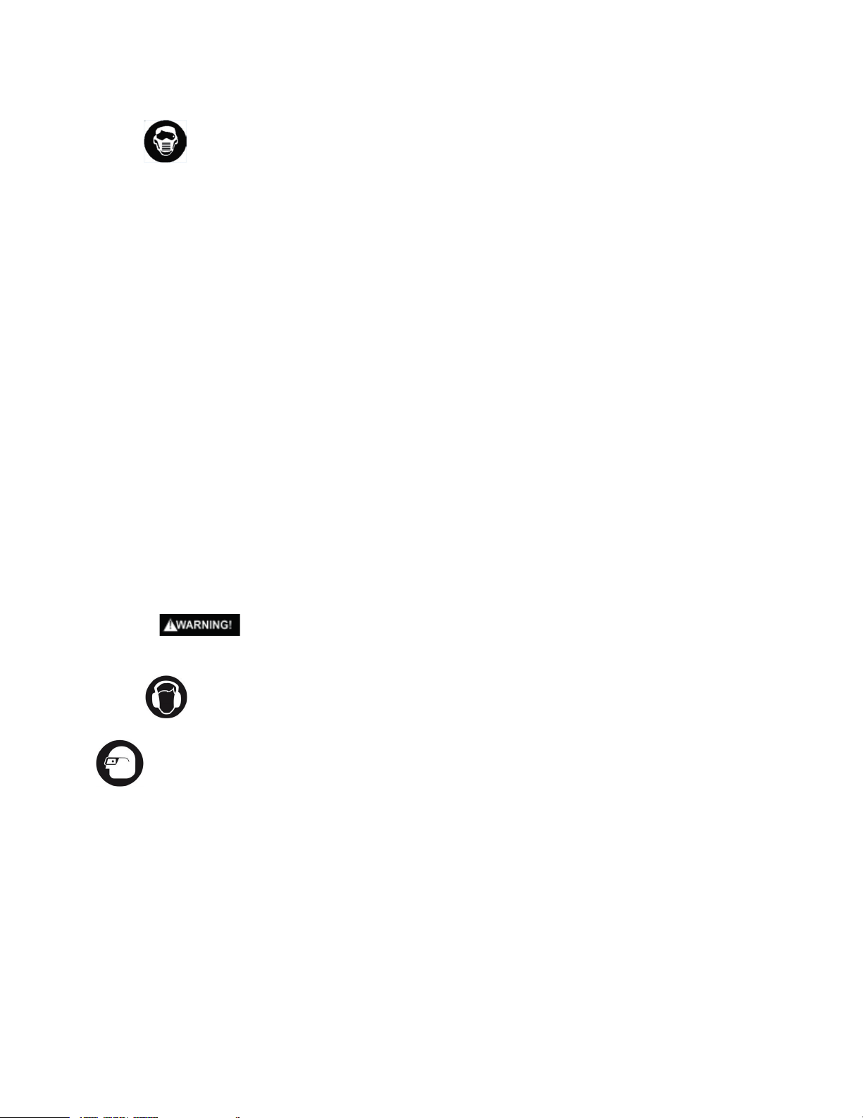
WEAR EYE PROTECTION: Always wear safety goggles or safety glasses with side shields.
WEAR RESPIRATORY AND HEARING PROTECTION: Always wear respiratory and hearing protection.
READ AND UNDERSTAND INSTRUCTION MANUAL: To reduce the risk of injury, users and all bystanders
must read and understand the instruction manual before using this product.
.
KEEP HANDS AWAY FROM THE MOVING PART AND CUTTING SURFACE: Failure to keep your hands away
from the moving part and cutting surface will result in serious personal injury.
3
Page 5

Some dust created by power sanding, sawing, grinding, drilling and other construction activities contains
chemicals known to the state of California to cause cancer, birth defects or other reproductive harm. Some
examples of these chemicals are:
● Lead from lead-based paints;
● Crystalline silica from bricks, cement, and other masonry products;
● Arsenic and chromium from chemically-treated lumber.
Your risk from these exposures varies, depending on how often you d
o this type of work. To reduce your
exposure to these chemicals: work in a well ventilated area, and work with approved safety equipment, such as
those dust masks that are specially designed to filter out microscopic particles. Avoid prolonged contact with
dust from power sanding, sawing, grinding, drilling, and other construction activities. Wear protective clothing
and wash exposed areas with soap and water. Allowing dust to get into your mouth, eyes, or lay on the skin
may
promote absorption of harmful chemicals.
Use of this tool can generate and/or disperse dust, which may cause serious and permanent respiratory
or other injury. Always use NIOSH/OSHA approved respiratory protection appropriate for the dust
exposure. Direct particles away from face and body.
POWER TOOL SAFETY
GENERAL SAFETY INSTRUCTIONS BEFORE USING THIS POWER TOOL
Safety is a combination of common sense, staying alert and knowing how to use your power tool.
To avoi
d mistakes that could cause serious injury, do not plug the tool in until you have read and understood the
following.
Read all instructions before operating the product. Failure to follow all instructions listed below may result in
electric shock, fire and/or serious injury.
1.
2.
3. KEEP GUARDS IN PLACE and in working order.
4. REMOVE ADJUSTING KE
adjusting wrenches are removed from the tool before turning ON.
5. KEEP WORK AREA CLEAN. Cluttered areas and benches invite accidents.
6. DO NOT USE IN DANGEROUS ENVIRONMENTS. Do not use power tools in damp locations, or expose
them to rain or snow. Keep the work area well lit.
7. KEEP CHILDREN AWAY. All visitors and bystanders should be kept a safe distance from the work area.
8. MAKE WORKSHOP CHILD PROOF with padloc
9. DO NOT FORCE THE TOOL. It will do the job better and safer at the rate for which it was designed.
10. USE THE RIGHT TOOL. Do not force the tool or an attachment to do a job for which it was not
designed.
11. USE PROPER EXTENSION CORDS. Make sure your extension cord is in good condition. When using an
extension cord, be sure to use one heavy enough to carry the current your product will draw. An
undersized cord will result in a drop in line v
overheat. The table on page 9 shows the correct size to use depending on cord length and nameplate
amperage rating. If in doubt, use the next heavier gauge. The smaller the gauge number, the heavier the
cord.
12. WEAR PROPER APPAREL. Do not wear loose clothing, gloves, neckties, rings, bracelets or other
jewelry which may get caught in moving parts. Non-slip footwear is recommended. Wear protective hair
covering to conta
READ and become familiar with the entire Instruction Manual.
LEARN the tool’s application, limitations and possible hazards.
YS AND WRENCHES. Form the habit of checking to see that keys and
ks, master switches or by removing starter keys.
oltage and in loss of power which will cause the tool to
in long hair.
13. ALWAYS WEAR EYE PROTECTION. Any power tool can throw foreign objects into the eyes and
could cause permanent eye damage. ALWAYS wear Safety Goggles (not glasses) that comply
with
4
Page 6
ANSI Safety standard Z87.1. Everyday eyeglasses have only impact–resistant lenses.They ARE NOT
safety glasses.
NOTE: Glasses or goggles not in compliance with ANSI Z87.1 could seriously injure you when they
break.
14. WEAR A FACE MASK OR DUST MASK. Grinding operation produces dust.
15. SECURE WORK. Use clamps or a vise to hold work when practical. It is safer than using your hand and
it frees both hands to operate the tool.
16. DISCONNECT TOOLS FROM POWER SOURCE before servi
as blades, bits, cutters, and grinding wheels.
17. REDUCE THE RISK OF UNINTENTIONAL STARTING. Make sure the switch is in the OFF position before
plugging the tool in.
18. USE RECOMMENDED ACCESSORIES. Consult this Instruction Manual for recommended accessories.
The use of improper accessories may cause risk of injury to yourself or others.
19. NEVER STAND ON THE TOOL. Serious injury could occur if the tool is tipped or if the cutting
unintentionally contacted.
20. CHECK FOR DAMAGED PARTS. Before further use of the tool, a guard or other part that is damaged
should be carefully checked to determine that it will operate properly and perform its intended
function– check for alignment of moving parts, binding of moving parts, breakage of parts, mounting
and any other conditions that may affect its operation. A guard or other part that is damaged should be
properly repaired or replaced.
21. NEVER LEA
running tool until the blade comes to a complete stop and the tool is unplugged from the power source.
22. DO NOT OVERREACH. Keep proper footing and balance at all times.
23. MAINTAIN TOOLS WITH CARE. Keep tools sharp and clean for best and safest performance. Follow
instructions for lubricating and changing accessories.
24. DO NOT use power tools in presence of flammable liquids or gasses.
25. DO NOT ope
affect your ability to use the tool properly.
26. Dust generated from certain materials can be hazardous to your health. Always operate grinder in a
well-ventilated area and provide for proper dust removal.
VE THE TOOL RUNNING UNATTENDED. TURN THE POWER “O”. Do not walk away from a
rate the tool if you are under the influence of any drugs, alcohol or medication that could
cing, and when changing accessories such
tool is
27. People with electronic devices, such as pacemakers, should consult their physician(s)
before using this product. Operation of electrical equipment in close proximity to a h
could cause interference or failure of the pacemaker
28.
WEAR HEARING PROTECTION to reduce the risk of induced hearing loss.
.
eart pacemaker
Bench Grinder Safety
1.
2. Use grinding wheels suitable for the speeds of the grinder.
3. Stand beside the bench grinder during start-up, not facing directly in front.
4. Do not remove the wheel guard.
5. Do not use the grinding wheel to cut anything.
6. Do not use anythin
7. Use a grinding wheel dressing tool to shape or remove glaze from grinding wheels.
8. Adjust distance between wheel and tool rest to maintain 1/8 inch (3.2 mm) or less separation as the diameter of
the wheel decreases with use.
9. Connect to an electrical supply circuit protected by a circuit breaker or time-delay fuse.
10. Secure the bench grinder to its supporting surface to prevent the grinder from tipping over, sliding, or walking
on its sup
Wear eye protection that complies with ANSI Z87.1 specifications.
g to stress the grinding wheel.
porting surface.
a. Replace a cracked wheel immediately.
b. Always use the guards and eye shields.
c. Do not overtighten the wheel nut.
d. Use only flanges furnished with this grinder.
5
Page 7

11. Always inspect grinding wheels prior to use for cracks, missing pieces, etc. Replace wheel immediately before
use.
12. USE ONLY GRINDING WHEELS that comply with ANSI B7.1 and rated greater than 3450 RPM.
13. GUARD AGAINST ELECTRICAL SHOCK by preventing body contact with grounded surfaces. For example:
pipes, radiators, ranges, refrigerator enclosures.
14. DO NOT use wheels with incorrect size holes. NEVER use wheel washers or wheel screws that are defective or
inco
rrect, and NEVER touch a grinding wheel or other moving parts.
15. NEVER reach to pick up a workpiece, a piece of scrap, or anything else that is in or near the grinding path of
the wheel.
16. AVOID AWKWARD OPERATIONS AND HAND POSITIONS where a sudden slip could cause your hand to move
into the wheel. ALWAYS make sure you have good balance.
17. NEVER stand or have any part of your body in line with the path of the wheel.
18. DO NOT USE TOOL IF SWITCH DOES NOT TURN IT ON AND OFF. Have defectiv
authorized service center.
19. DO NOT TURN THE MOTOR SWITCH ON AND OFF RAPIDLY. This could cause the wheel to loosen and create a
hazard. Should this ever occur, stand clear and allow the wheel to come to a complete stop. Disconnect your
grinder from the power supply and retighten the wheel nut securely.
20. RISK OF INJURY DUE TO ACCIDENTAL STARTING. Do not use in an area where children may be present.
21. NEVER START THE GRINDER when the wheel is in contact
22. SECURE WORK. Always hold the workpiece firmly against the work rest.
23. DO NOT USE THE BENCH GRINDER if the flange nut or clamp nut is missing or if the spindle shaft is bent.
24. FREQUENTLY clean grinding dust from beneath the grinder.
25. DO NOT OPERATE THIS TOOL WHILE UNDER THE INFLUENCE OF DRUGS, ALCOHOL OR ANY MEDICATION.
26. ALWAYS STAY ALERT. Do not allow familiarity (gained from frequent use of your grinder) to cause a careless
mistake. ALWAYS REM
27. STAY ALERT AND EXERCISE CONTROL. Watch what you are doing and use common sense. Do not operate the
tool when you are tired. Do not rush.
28. SAVE THESE INSTRUCTIONS. Refer to them frequently and use them to instruct other users. If you loan
someone this tool, loan them these instructions also.
29. ALWAYS EASE THE WORKPIECE AGAINST THE ABRASIVE WHEEL when starting to grind. A harsh impact can
br
eak the wheel. Use light pressure when starting to grind. Too much pressure on a cold wheel can cause the
wheel to crack.
30. USE ONLY FLANGES furnished with this bench grinder.
31. IF ANY PART OF THIS GRINDER IS MISSING or should break, bend, fail in any way, or should any electrical
component fail to perform properly,shut off the power switch, remove the machine plug from the power source
and have damaged, missing, or failed parts replaced before resuming operation.
32. SAFET
convenience. Operating the grinder without these features attached could result in serious injury. Do not grind
with the safety shield raised. Always wear safety glasses for personal protection.
33. WORK REST. The work rests are independently adjustable to compensate for wheel wear. Before grinding,
make certain the work rests are adjusted properly. Generally, the obje
center of the grinding wheel
Y SHIELD AND SPARK DEFLECTOR. The safety shields and spark deflectors are adjustable for operator
EMBER that a careless fraction of a second is sufficient to inflict severe injury.
with the workpiece.
ct being ground is done slightly above the
e switches replaced by an
34. Lawn mower blades are usually sharpened on only one edge and dressed up slightly on the other. Perform this
sharpening process on both cutting ends of the blade. After sharpening, balance the blade by removing
additional material.
6
Page 8
POWER SUPPLY AND MOTOR SPECIFICATIONS
To avoid electrical hazards, fire hazards, or damage to the tool, use proper circuit protection. Use a separate
electrical circuit for your tool. Your drill press is wired at the factory for 120 V operation. Connect to a 120 V, 10
Amp circuit and use a 10 Amp time delay fuse or circuit breaker. To avoid shock or fire, if the power cord is worn,
cut, or damaged in any way, have it replaced immediately.
GROUNDING INSTRUCTIONS
This tool must be grounded while in use to protect the operator from electrical shock.
IN THE EVENT OF A MALFUNCTION OR BREAKDOWN, grounding provides a path of least resistance for electric
currents and reduces the risk of electric shock. This tool is equipped with an electrical cord that has an
conductor and a grounding plug. The plug must be plugged into a matching receptacle that is properly installed and
grounded in accordance with all local codes and ordinances.
DO NOT MODIFY THE PLUG PROVI
DED. If it will not fit the receptacle, have the proper receptacle installed by a
qualified electrician.
IMPROPER CONNECTION of the equipment grounding conductor can result in risk of electric shock. The conductor
with the green insulation (with or without yellow stripes) is the equipment grounding conductor. If repair or
replacement of the electrical cord or plug is necessary, do not connect the equipment grounding conductor to a live
terminal.
CHECK with a qualified e
lectrician or service person if you do not completely understand the grounding instructions,
or if you are not certain the tool is properly grounded.
USE only 3-wire extension cords that have three-pronged grounding plugs with three-pole receptacles that accept the
tool’s plug. Repair or replace damaged or worn cords immediately.
Use a separate electrical circuit for your tool. This circuit must not be less than #18 wire and should be protected with a
10 Amp time lag fuse.
Before connecting the motor to the power line, make sure the switch is in the off position and the
electric current is rated the same as the current stamped on the motor nameplate. Running at a lower voltage will
damage the motor.
GUIDELINES FOR EXTENSION CORDS USE THE PROPER EXTENSION CORD. Make sure your extension cord is in
good condition. Use an extension cord heavy the current your product will draw. An undersized cord will cause a drop
in line voltage resulting in loss of po
wer, overheating and burning out of the motor. The table below shows the correct
size to use depending on cord length and nameplate ampere rating. If in doubt, use the next heavier gauge. The smaller
the gauge number, the heavier the cord.
Make sure your extension cord is properly wired and in good condition. Always replace a damaged extension cord or
have it repaired by a qualified technician before using it. Protect your extension cords from sharp objects, excessive
heat an
d damp or wet areas.
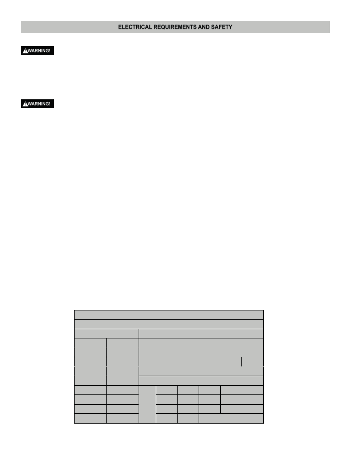
MINIMUM GAUGE FOR EXTENSION CORDS (AWG)
(WHEN USING 120 VOLTS ONLY)
Ampere Rating Total Length of Cord
More Not More 25 50 100 150 ft.
Than Than (7.62 15.24 30.48 45.72 m)
AWG - American Wire Gauge
0 6 18 16 16 14
6 10 18 16 14 12
10 12 16 16 14 12
12 16 14 12 Not Recommended
7
Page 9
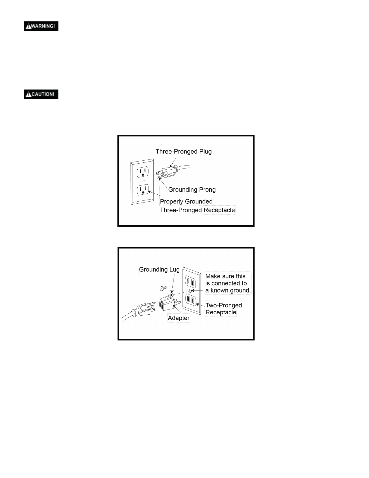
This tool is for indoor use only. Do not expose to rain or use in damp locations.
This tool is intended for use on a circuit that has a receptacle like the one illustrated in Fig. 1. Fig. 1 shows an
electrical plug and receptacle that has a grounding conductor. If a properly grounded receptacle is not available,
an adapter (Fig.2) can be used to temporarily connect this plug to a two-contact grounded receptacle. The
adapter (Fig. 2) has a rigid lug extending from it that MUST be conn
properly grounded receptacle box.
In all cases, make certain the receptacle is properly grounded. If you are not sure, have a qualified electrician
check the receptacle.
ected to a permanent earth ground, such as a
Figure 1
Figure 2
8
Page 10
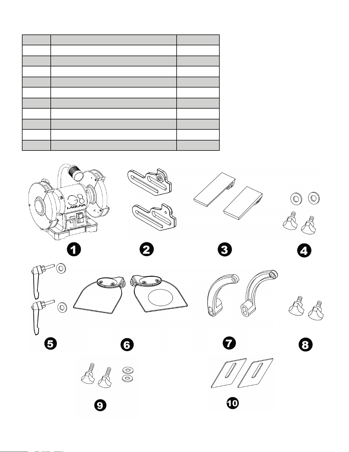
UNPACKING YOUR G8 BENCH GRINDER
Number Description Quantity
1 G8 Bench Grinder 1
2 Left / Right tool rest bracket 1 each
3 Left / Right tool rest 1 each
4 Tool rest bracket knob / flat washer 2
5 Tool rest lock handle / flat washer 2
6 Left / Right eye shield assembly 1 each
7 Left / Right eye shield bracket 1 each
8 Eye Shield locking knob 2
9 Eye shield bracket knob / flat washer 2
10 Spark deflector 2
9
Page 11
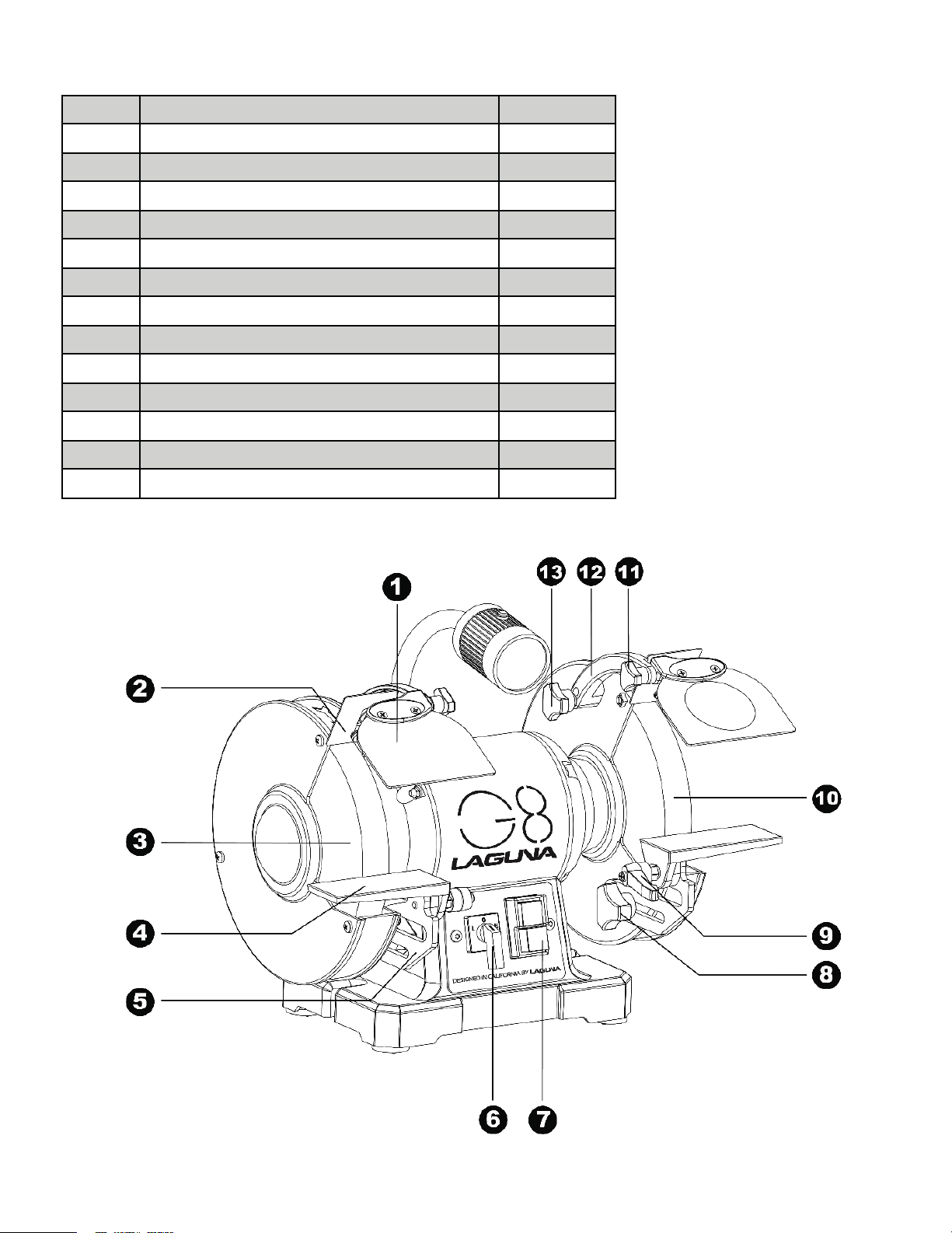
KEY PARTS DIAGRAM
Number Description Quantity
1 Eye Shield 2
2 Spark Deflector 2
3 60 Grit White Aluminum Oxide Grinding Wheel 1
4 Tool Rest 2
5 Tool Rest Bracket 2
6 Dual Speed Switch 1
7 Main On / Off Switch 1
8 Tool Rest Bracket Knob 2
9 Tool Rest Lock Handle 2
10 120 Grit White Aluminum Oxide Grinding Wheel 1
11 Eye Shield Lock Knob 2
12 Eye Shield Bracket 2
13 Eye Shield Bracket Knob 2
10
Page 12
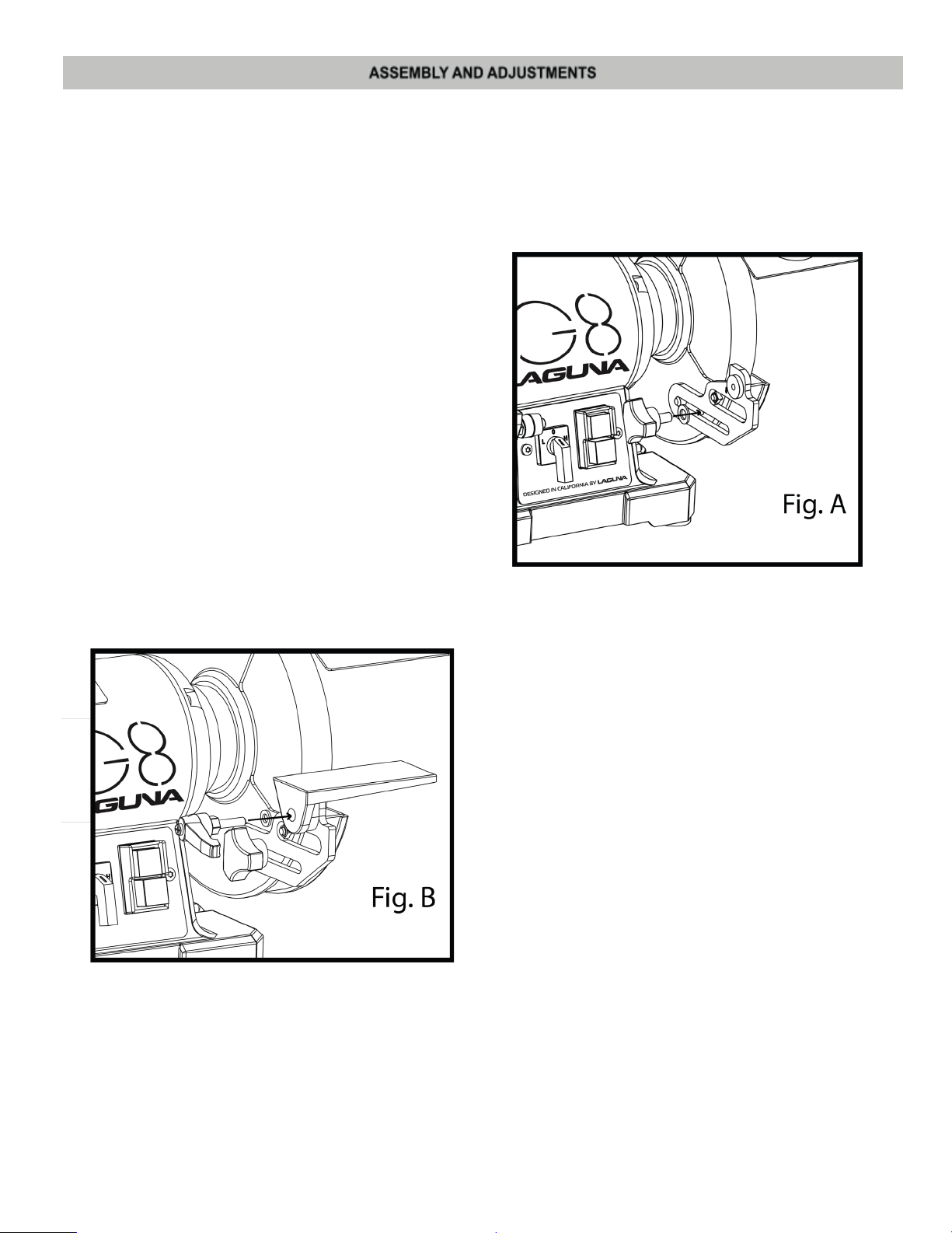
Estimated Assembly Time: 5 - 10 minutes.
● To avoid injury, do not connect this bench grinder to the power source until it is completely assembled
and adjusted, and you have read and understood the instructions and warnings in this manual.
● To reduce the risk of injury, turn off and disconnect the grinder from the power source before installing
and removing accessories, before adjusting or making repairs, or replacing the wheels. An accidental
start-up can cause serious in
INSTALLING TOOL RESTS
(FIG. A, B)
1. Attach the right tool rest bracket to the
right wheel guard using a bracket knob
and flat washer as shown in Fig A.
NOTE: Ensure the locating pin passes
Through the bracket as shown and the
registration disc of the bracket is facing
Inwards as shown.
jury.
2. Attach the right tool rest to the bracket using
a tool rest locking knob as shown in Fig. B.
Ensure that the flat profile of the tool rest
is facing towards the grinding wheel.
NOTE: When in use,
adjusted to within 1/16” (1.6 mm) of the grinding
wheel or other accessory being used.
3. Attach the left tool rest following the same
procedure as above.
the tool rests should be
11
Page 13
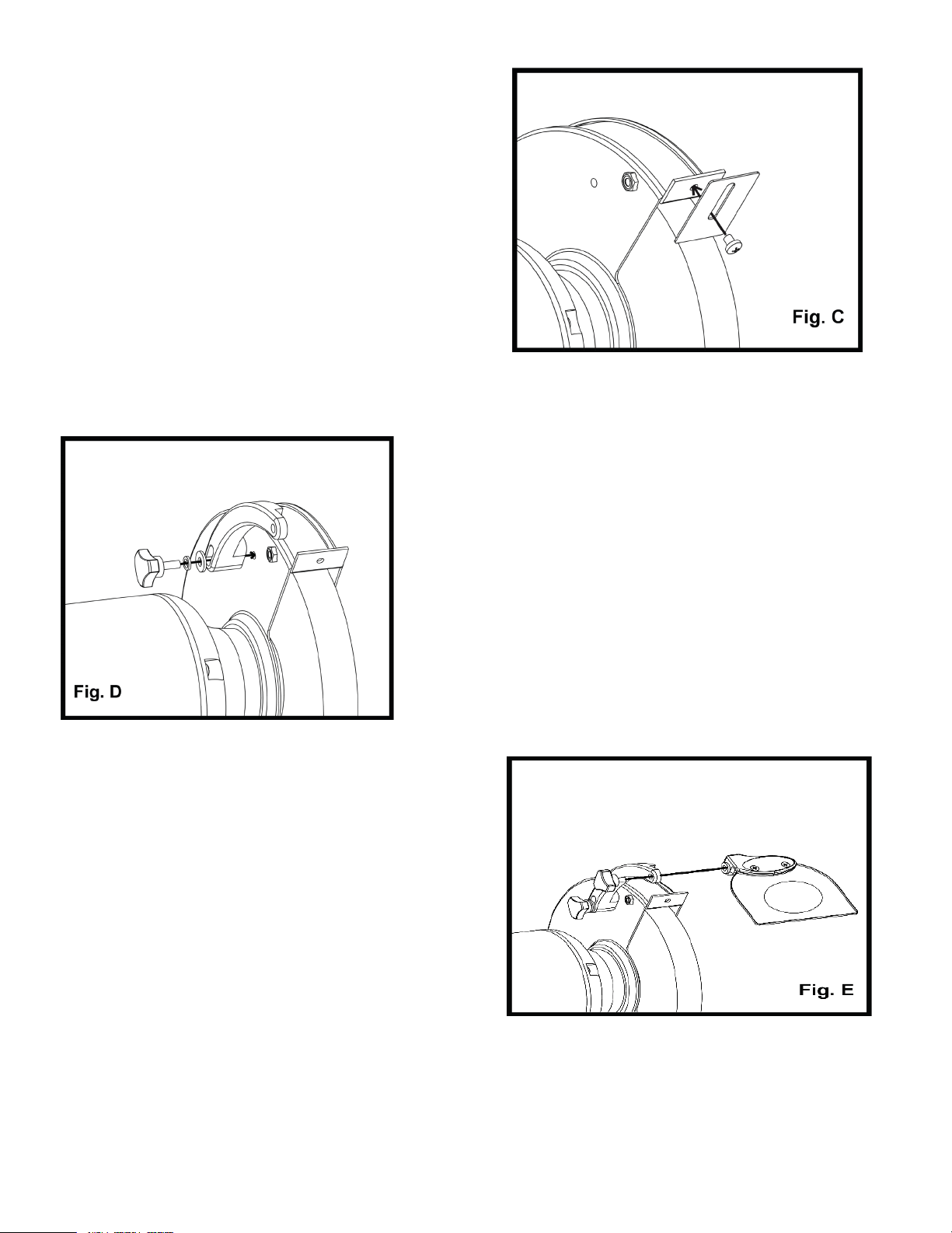
INSTALLING SPARK DEFLECTOR
(FIG C)
1. Use an M5x10 screw, washer and
spring washer to attach the left
spark deflector to the left wheel
guard as shown in Fig. C.
Secure the screw in place with a
Phillips screwdriver.
2. Attach the right spark deflector
following the same procedure as
above.
INSTALLING EYESHIELD ASSEMBLY
(FIG. D, E)
2. Fasten the right eye shield to the eye shield
bracket using the dye shield locking knob.
3. Attach the left eye shield assembly following
the same procedure as above.
1. Attach the right eye shield bracket to the wheel
guard using a flat washer, spring washer, and
eye shield bracket knob.
NOTE: The slotted part of t
must face towards the grinding wheel guard.
he eye shield bracket
12
Page 14
Keep all bystanders a safe distance away from the tool and not in direct line, front or back of the grinder.
1. Your bench grinder has a white fin wheel (120 grit) for medium material removal and general purpose
grinding, and a white medium wheel (60 grit) for fast material removal.
2. To operate the bench grinder, always wear safety glasses and turn the tool on while standing at the side
and not in front of the grinder. Allow it to reach full speed before grinding.
3. Hold the workpi
clamps.
4. Feed the workpiece smoothly and evenly into the grinding wheel.
5. Move the workpiece slowly and avoid jamming the workpiece against the wheel. If the wheel tends to slow
down from excessive force, you should occasionally release the pressure to let the wheel return to full
speed.
6. The grinding wheels supplied with this unit are designed for different types of steel, wrought ir
bronze.
7. Never sharpen or grind anything made of aluminum, brass, copper, wood, plastic or any other
non-metallic materials.
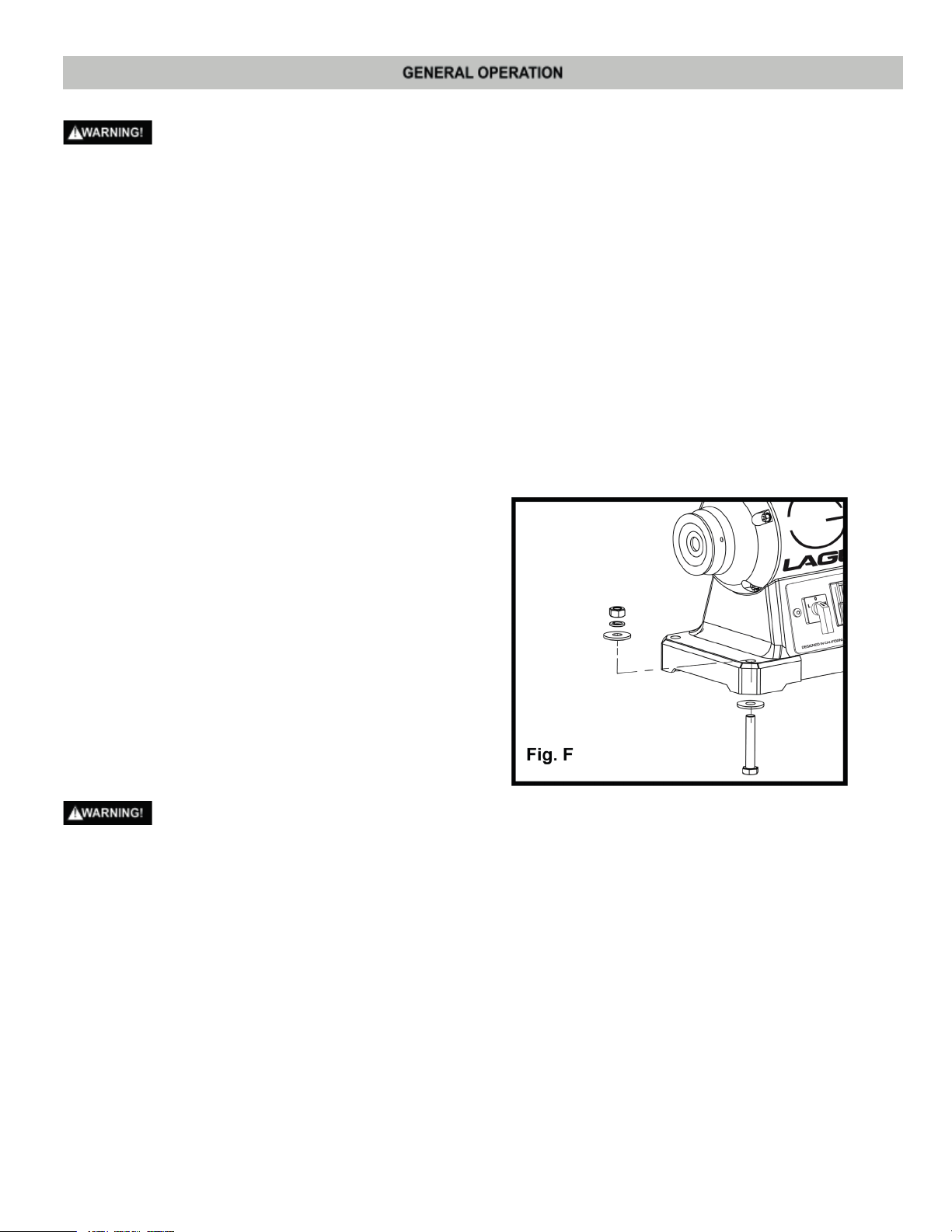
MOUNTING THE TOOL ON A WORKBENCH
(FIG. F)
NOTE: FIRMLY BOLT THE GRINDER TO A
WORKBENCH OR LEG STAND to gain
maximum stability for your machine.
ece firmly against the tool rest. Hold very small pieces with pliers or other suitable
on, and
1. Using the base of the bench grinder as
a template, mark the bench through the
four holes in the base of the casting.
2. Bolt the bench grinder on the bench with
bolts, washers, and nuts.
NOTE: The mention
With the machine.
To reduce the risk of injury, turn off the grinder and disconnect it from the power source before installing and
removing accessories, adjusting and making repairs. An accidental start-up can cause injury.
In order to conveniently carry the bench grinder from place to place, hold the left and right side of the wheel
cover for transportation.
ed fasteners are not supplied
13
Page 15
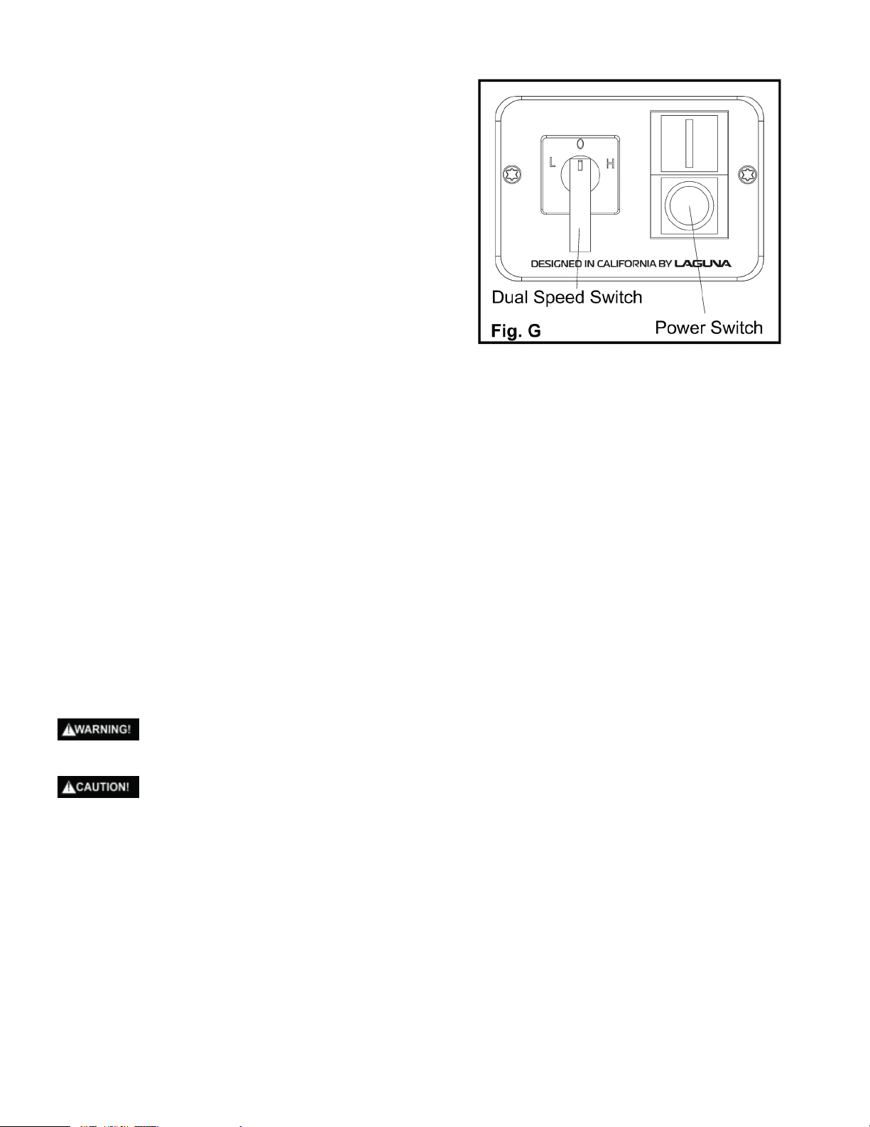
ON/OFF Switch
(Fig. G)
1. Press the power switch side marked “I”
and turn the dual speed switch to H or L
position to turn the grinder on.
2. Press the power switch side marked “O”
to turn the grinder off
ADJUSTING THE SPEED OF THE GRINDER
Your grinder is equipped with a dual speed control switch.
1. To select High Speed, turn the dual speed switch to
the side marked “H”.
2. To select Low Speed, turn the dual speed switch to
the side marked “L”.
NOTE: For your own safety, when changing spe
“O” position and wait 3-5 seconds and then change to Low Speed. When changing from Low to High, always
turn the dual speed switch to the “O” position and wait 3-5 seconds and then change to High Speed.
Grinding
1. Adjust the tool rest to accommodate large or unusually shaped workpieces.
2. Always keep the workpiece moving across the face of the grinding wheel. Grinding continuously on the same spot
on the wheel will caus
easily, and grinding of other objects will be difficult.
3. If the workpiece becomes hot, dip it into water or oil to cool it.
4. Always grind on the face of the wheel (around the diameter), NEVER on the sides. Side pressure on grinding
wheels can cause cracking and damage.
5. If the face of the grinding wheel is worn unevenly, becomes grooved, or is no longer smooth and flat, the wheel
should be reshaped wi
6. If the grinding wheel is no longer round, the wheel should be reshaped with a dressing tool or replaced.
7. If the surface of the wheel becomes loaded and dull with workpiece material, the wheel should be cleaned with a
dressing tool.
8. After reshaping, always readjust the tool rests and spark arrestors.
Grind only on the face of the grinding wheel and never the side of the wheel.
e grooves to be worn into the wheel. The wheel may crack or become damaged more
th a dressing tool.
eds from High to Low, always turn the dual speed switch to the
Prolonged grinding will cause most materials to become hot. Use care when hand
SCISSORS
If possible, take the scissors apart to make the sharpening operation easier and safer.
Remove material only from the outside surface and work from the heavy end of the blade toward the tip.
KNIVES
Remove metal from both faces of most knives, working from the heavy end of the blade toward the tip.
SCREWDRIVERS
The end of a properly sharpened screwdriver will be a perfect rectangle, absolutely flat and perpendicular to the center
line of the shank
flat with intersecting faces perpendicular. Hold each face of the screwdriver against the wheel to true it up, then ease the
end straight into the stone to grind it true.
. The two sides and two faces will taper outward from the edge of the shoulder or shank. They should be
ling such materials.
14
Page 16
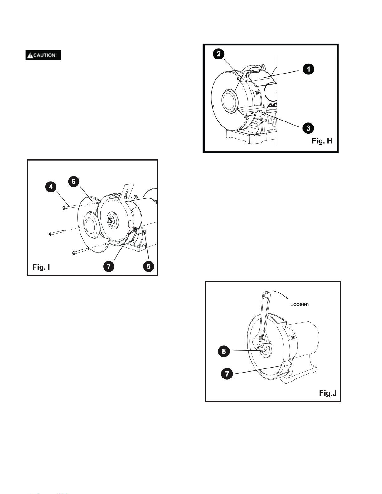
CHANGING GRINDING WHEELS
(FIG. H, I, J, K, L)
Turn off and unplug the bench grinder.
Use only grinding wheels that measure
8 in. (200 mm) in diameter. This tool has
5/8 in. (15.88 mm) arbors on both sides.
1. Raise the eye shield (1) out of the way
and adjust the spark guard (2) in its
highest setting.
2. Loosen the knob and remove the
tool rest assembly (3).
3. Loosen three screws (4) from the side wheel
cover and then remove the outer cover (6).
4. To prevent wheel rotating, place a wood
wedge (7) (not supplied) between the wheel
and the wheel cover as shown in Fig. I.
NOTE: Using a metal object, like a
screwdriver is not recommended as it may
damage the grinding wheel.
5. Loosen the hex nut (8) with an adjustable
Wrench as shown in Fig. J.
NOTE: The nut on the left side of the grinder
has standard left-hand thread (turn
counterclockwise to loosen). Both wheel
nuts tighten when turning toward the rear
of the grinder and loosen when turned toward
the front of the grin
der.
15
Page 17
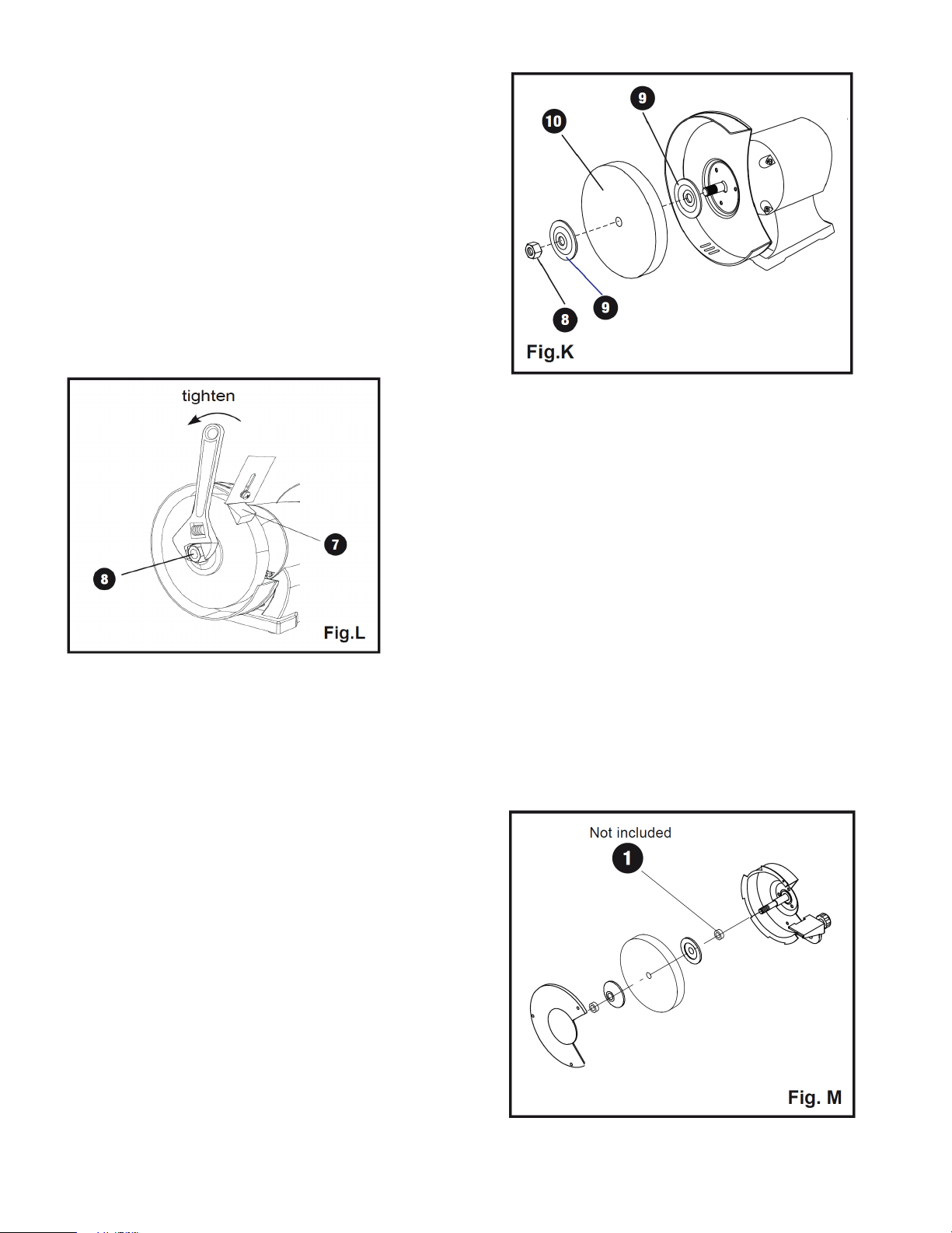
6. Remove the hex nut (8), the outside
wheel flange (9) and the wheel (10)
as shown in Flg. K.
7. Inspect the wheel (10) for cracks, chips
or any other visible damage (other
than normal wear) and discard if such
damage is found. Inspect the blotter/
cardboard disc for damage. If the blotter
is missing or severely damaged, replace
it with a piece of thin cardboard or
blotter paper cut in the same shape.
NEVER USE A GRINDING WHEEL
WITHOUT A BLOTTER.
8. Install the new wheel and make sure
wheel flanges (9) are in place with the
concave sides toward wheels.
9. To prevent wheel rotating, place a wood
wedge (7) (not supplied) between the
wheel and the wheel cover as shown
in Fig. L.
10. Tighten the hex nut (8) by an adjustable
wrench.
NOTE: Do not overtighten the nut as this can crack the grinding wheel.
11. Replace the wheel cover (6) and screws (4).
12. Reinstall and adjust the tool rest to 1/16” (1.6 mm) away from the wheel and tighten securely.
13. Adjust the eye s
hield (1) to a point between your eyes and the wheel.
both
BUFFING WHEEL OR WIRE WHEEL
A buffing wheel (not included) or wire wheel
(not included) can be used with your grinder.
You will need to add one or more spacers ( 1 )
to allow the arbor hex nut to tighten correctly.
Wire wheel: 8 x 5/8" with a maximum speed
of 4500 RPM.
16
Page 18
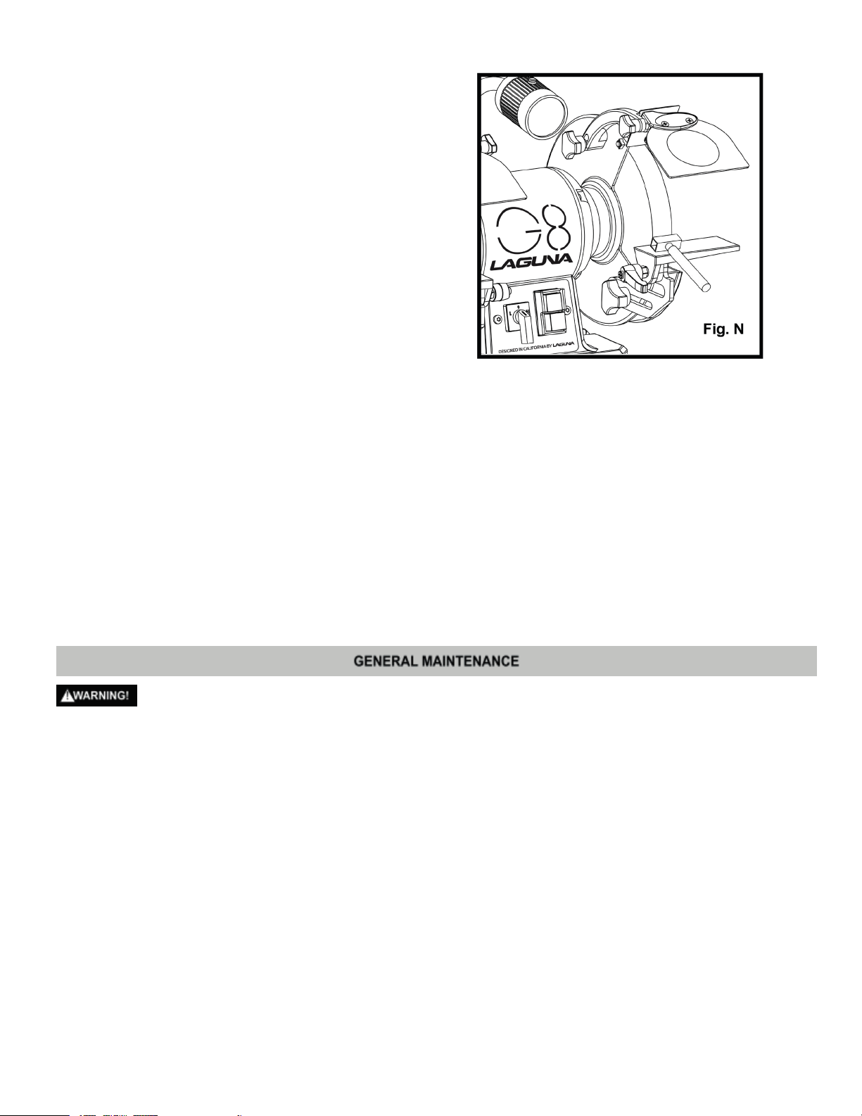
DRESSING A GRINDING WHEEL
(FIG. N)
A Wheel Dressing Tool is to be used
to remove any forward wobble, buildup
of material on the grinding wheel, remove
imperfections, and make the corners of
the grinding wheel square.
NOTE: DO NOT use the Wheel Dresser
on wire wheels (not included) if they are
installed on the grinder.
1. Adjust tool rest until it is in the flat horizontal position as shown and 1/16” away from the grinding wheel.
2. Turn on the Bench Grinder. Let the grinding wheel c
3. After the grinding wheel has gotten to a steady speed, place the Wheel Dresser head flat on the Tool Rest.
4. Firmly hold on to the handle of the Wheel Dresser.
5. Move the Wheel Dresser forward until it makes light contact with the grinding wheel. After contact has been made,
slide the Wheel Dresser side to side across the Tool Rest to dress the grinding wheel until the edges of the
grinding wheel are square and the surface is clean.
6. After d
Allow the grinding wheel to cool down for a period of 10 minutes before use.
7. Inspect the grinding wheel for any irregularities that still need to be dressed, or for any damage. If there is damage
to the wheel (cracks, major chips missing), replace the wheel immediately.
8. The grinding wheel may now be slightly smaller in diameter after dressing. Re-adjust the tool rests
arrestors to maintain a 1/16” clearance to the grinding wheel.
ressing the grinding wheel, turn off the Bench Grinder and let the grinding wheel come to a complete stop.
ome up to a steady speed for one minute.
and spark
For your own safety, turn the switch “OFF” and remove the plug from the power source outlet before adjusting
and maintaining your bench grinder. If the power cord is worn, cut or damaged in any way, have it replaced
immediately.
1. Regularly check the tool and use a soft brush to remove accumulated dust.
2. Use only mild soap and damp cloth to clean the tool. Do not use alcohol, petrol or other similar cleanin
3. Do not make contact with the grinding wheels with any damp cloth.
4. Never let any liquid get inside the tool. Never immerse any part of the tool into a liquid.
5. Wear safety goggles to protect your eyes while cleaning.
6. Always make sure the eye shields are transparent and not blocking the view of the grinding wheel.
7. In normal use, grinding wheels may become cracked, grooved, rounded at the edges, chipped, out of true or
loaded with foreign material. Cracked whee
conditions can be remedied with a dressing tool (included), new wheels sometimes require dressing to make them
round.
8. If you must replace a wheel be sure to obtain one with a safe rated speed at least as high as the “NO LOAD” RPM
marked on your grinder’s nameplate. Replacement wheels must have a 5/8 in. (15.88 mm) center hole, 8 in. (200
mm) diameter and should be a maximum of 1 in. (25 mm) wide. Test new wheels for cracks and
existing sequence of retaining hardware. Be sure the tool is unplugged before attempting repairs.
ls should be replaced IMMEDIATELY. While any of the other
g agents.
maintain the
17
Page 19

● Never use caustic agents to clean the plastic parts of the tool.
● Water must never come into contact with the grinder.
● The use of any other accessories is not recommended and may result in serious injury.
GENERAL
SYMPTOM PROBABLE CAUSE CORRECTIVE ACTION
Motor will not run.
Grinding wheel
vibrates or shakes.
Not plugged into power
outlet.
Power switch is not in
the ON position.
Motor cord cut or
abraded
Plug on cord is faulty.
Faulty motor.
Fuse or circuit breaker
open.
Grinding wheel is not
secured properly.
Other
Plug into the power outlet.
Turn the switch ON. Dual
speed switch not at "O"
position.
Contact Professional
Service Station for repair.
Contact Professional
Service Station for repair.
Contact Professional
Service Station for repair.
Reset breaker; may be too
many machines on circuit
Adjust grinding wheel
properly. See
ADJUSTMENT section.
Contact Professional
Service Station for repair.
18
Page 20
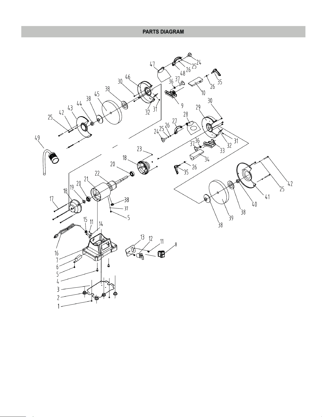
19
Page 21

Number Description Specification Quantity
1 Phillips screw + flat washer M4x8 2
2
3
4 Hex bolt + spring washer M8x22 2
5 Phillips screw + spring washer + flat washer M4x8 1
6
7
8
9
10
11 Star screw (black) M5x8 4
12
13
14
15
16
17 Phillips screw + flat washer M5x155 4
Rubber feet 4
Base cover 1
Capacitor 1
Base 1
NVR Switch 1
Left fixed work rest 1
Left movable work rest 1
Speed adjustment switch 1
Switch plate 1
Cord clip plate 1
Cord Clip 1
Plug and cord 1
18
19 Wave spring washer D47 1
20 Bearing 6204 2
21
22
23 Hex nut M5 4
24
25 Spring washer D6 2
26 Flat washer D6 4
27
28
29
30 Phillips screw + spring washer M5x10 6
31 Phillips screw + spring washer + flat washer M5x8 2
32
33
Right eye shield support 1
Right eye shield magnifier assembly 1
End cap 1
Stator 1
Rotor 1
Eye shield lock knob 2
Right inner guard 1
Spark deflector 2
Right fixed work rest 1
34
35
Right moveable work rest 1
Moveable work rest lock knob 2
20
Page 22

36 Flat washer D8 2
37
38
39 White grinding wheel φ200X25Xφ15.88mm 120# 1
40 Hex nut M12 1
41
42 Phillips screw M5x48 6
43
44 Hex nut M12 Left Hand 1
45 White grinding wheel φ200X25Xφ15.88mm 60# 1
46
47
48
49
Fixed work rest lock knob 2
Flange 4
Right wheel guard cover 1
Left wheel guard cover 1
Left inner guard 1
Left eye shield assembly 1
Left eye shield support 1
LED Lamp 1
21
Page 23

Warranty
New machines and accessories sold by Laguna Tools carry a one-year
warranty effective from the date of shipping.
Laguna Tools guarantees all new machines and accessories sold to be
free of manufacturers’ defective workmanship, parts and materials.
We will repair or replace, without charge, any parts determined by
Laguna Tools, Inc. to be a manufacturer’s defect.
We require that the defective item/part be returned to the Laguna
appointed dealer you purchased from with the complaint. Photo
graphic / videos maybe required when any fault is reported so we can
agree action needed. Any machines returned to Laguna appoint
ed dealer must be returned with packaging in the same manner
in which it was received. If a part or blade is being returned it must
have adequate packaging to ensure no damage is received during
shipping. In the event the item/part is determined to be damaged
due to lack of maintenance, cleaning or misuse/abuse, the customer
will be responsible for the cost to replace the item/part, plus all relat
ed shipping charges. This limited warranty does not apply to natural
disasters, acts of terrorism, normal wear and tear, product failure due
to lack of maintenance or cleaning, damage caused by accident,
neglect, lack of or inadequate dust collection, misuse/abuse or dam
age caused where repair or alterations have been made or attempted
by others. Laguna Tools, Inc. is not responsible for additional tools or
modifications sold or performed (other than from/by Laguna Tools,
Inc.) on any Laguna Tools, Inc. machine.
-
-
-
-
Warranty maybe voided upon the addition of such described tools
and/or modifications, determined on a case-by-case basis.
Normal user alignment, adjustment, tuning, machine settings and
consumables I.E; blades are not covered by this warranty. It is the
responsibility of the user to understand basic machinery operation,
settings and procedures and to properly maintain the equipment in
accordance with the standards provided by the manufacturer.
The labour required to install replacement parts is the responsibility
of the user. Laguna Tools is not responsible for damage or loss caused
by a freight company or other circumstances not in our control.
All claims for loss or damaged goods must be notified to the author
ised dealer within twenty-four hours, if the machine is received damaged it must be signed for damaged.
Only new machines sold to the original owner are covered by this
warranty.
-
22
Page 24

Declaration of Conformity
Nationality
GB
DE
FR
IT
ES
NL
DK
The object of the declaration described is in conformity
with the relevant GB/EU legislation.
Der Gegenstand der beschriebenen Erklärung stimmt mit
den einschlägigen GB/EU-Rechtsvorschriften überein.
L’objet de la déclaration décrite est conforme à la
législation GB/UE pertinente.
L’oggetto della dichiarazione descritta è conforme alla
legislazione GB/UE pertinente.
El objeto de la declaración descrita está en conformidad
con la legislación GB/UE pertinente.
Het voorwerp van de beschreven verklaring is in
overeenstemming met de relevante GB/EU-wetgeving.
Genstanden for den beskrevne erklæring er i
overensstemmelse med den relevante GB/EU-lovgivning.
Nationality
SE
CZ
PL
POR
NOR
FI
IS
Föremålet för den beskrivna deklarationen
överensstämmer med den relevanta GB/EU-lagstiftningen.
Předmět popsaného prohlášení je v souladu s příslušnými
právními předpisy GB/EU.
Przedmiot opisanej deklaracji jest zgodny z odpowiednimi
przepisami GB/UE.
O objeto da declaração descrita está em conformidade
com a legislação GB/UE relevante.
Gjenstanden for den beskrevne erklæringen er i samsvar
med den relevante GB/EU-lovgivningen.
Määritellyn ilmoituksen kohde on asiaankuuluvan IsonBritannian/EU: n lainsäädännön mukainen.
Hluturinn í lýsingunni er í samræmi við viðeigandi lög
GB/ESB.
Distributed by
The packaging is suitable for recycling.
Please dispose of it in a responsible manner.
EU Countries Only
Do not dispose of electric tools together with household waste material.
By law they must be collected and recycled separately.
For after sales help visit
axminstertools.com or call 03332 406406
Axminster Tools, Axminster Devon EX13 5PH
 Loading...