

Page 1
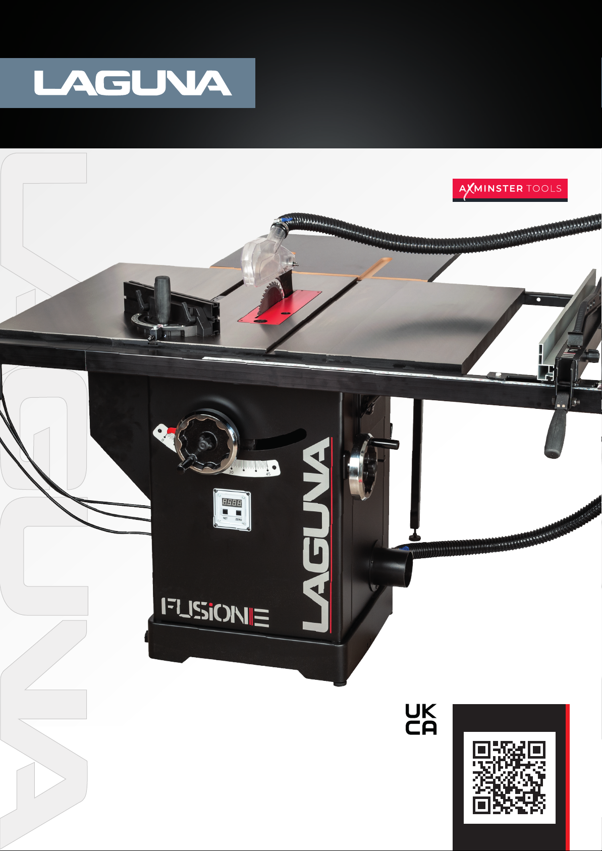
F3 Fusion
Table Saw 230v
Code: 111786
Distributed by
N.B. Some pictures and diagrams in this manual may have buttons and electrical configurations
which differ slightly from the machine you purchased
Version: 4
Date: 1/10/25
DIGITAL MANUAL
Page 2

Contents
Dear Woodworker 3
Specifications 5
Top 10 Features 6
Safety 6
Tool Overview 7
Controls 7
Setup 8
Loose Parts & Overview 9
General Setup 9
Rear Extension Table 10
Installing/Removing the Throatplate 12
Installing/Removing Safety Accessories 13
Installing/Removing the Blade 14
Adjustments 15
Fence Adjustments 16
Table Adjustments 16
Arbor and Tilt Adjustments 18
Accessory Adjustments 19
Push Block 20
Type of Cut 21
Maintenance 23
Internal Components Map 23
Trouble-Shooting 24
Wiring Diagram: Fusion F3 230V 25
Parts Diagrams 26
Parts List 31
Manufacturers warranty 38
Conformity Certificates 39
2
Page 3
2
© 09/2019, Laguna Tools, Inc.
About
This Manual
machine.
Fusion Tablesaw
Please dispose of packaging for the product in a responsible manner. It is suitable for
Dear Woodworker
Thank
you for your purchase and welcome to the Laguna Tools group of discerning woodworkers. We understand that you have a choice of where to
purchase your machines and appreciate the confidence you have in the Laguna Tools brand.
Every machine sold by Laguna Tools has been carefully designed and well thought through from a woodworker’s perspective. Through hands-on
experience, Laguna Tools are constantly working hard to make innovative, precision products. Products that inspire you to create works of art, are a
joy to run and work on, and encourage your performance.
Laguna Tools®
Imagination, Innovation, and Invention at work.
This manual is intended to thoroughly cover the setup up, maintenance,
and proper adjustments of your new purchase. Aside from the
proceeding general
woodworking or metalworking techniques that are possible with this
product and the appropriate safety precautions necessary for safe
practices. There are several organizations with published safe practices,
techniques, and proper operation of this tool:
safety considerations, this manual DOES NOT cover
Power Tool
www.powertoolinstitute.com
Institute
warning: Indicates a possible threat that can result in death to
the operator and/or bystanders and cause severe damage to the
Use
Caution: Indicates a possible threat that will result in minor
injury and damage to the machine.
Tech
Tip: Indicates a technical tip that can help the
action, process, or procedure described. The QR Code
will be present when applicable content is available.
Notice: Indicates important information to the user about
questionable subject, objects of importance, or is used to explain an
event that may result in unwarranted damage to the machine.
recycling. Help to protect the environment, take the packaging to the local amenity tip and
place into the appropriate recycling bin.
Only for EU countries Do not dispose of electric tools together with household waste
material! In observance of European Directive 2002/96/EC on waste electrical and
electronic equipment (EEE) and its implementation in accordance with national law, electric
tools that have reached the end of their life must be collected separately and returned to an
environmentally compatible recycling facility. Your local refuse amenity will have a separate
collection area for EEE goods.
3
Page 4
4
© 09/2019, Laguna Tools, Inc.
Fusion Tablesaw
TABLESAW
SPECIFIC
GENERAL
ELECTRICAL
NCLUDED WITH
PURCHASE
NAME
& MODEL
Fusion Tablesaw
Fusion 3 Tablesaw
Advertised Name Fusion 3 Table saw
Stock Model CEF33623003
Professional Square Zero Clearance Throat Plate (pre-installed)
10" 40T Blade (pre-installed)
Riving Knife (pre-installed)
Mitre Gauge (ships in tool holder)
Tool Holder (pre-installed)
Fence
Blade Guard
Arbor Wrench
Installation and Adjustment Tools
Phase 1PH
Voltage 230V
Motor Type TEFC Capacitor Start AC Induction
Rating Input 2200 W
Motor Speed 2850 /min
Cycle 50 Hz.
Full Load Amperage 14.5 Amp.
Start Capacitor 400 µF-U
Run Capacitor 50 µF-U
Switch Type Magnetic with Overload Protection
Power Transfer Single V-Ribbed Belt 142J FJ
Power Cord 2m. H07RNF
Power Plug Included CEE 7/7 Plug
Breaker Recommendation 30 Amp.
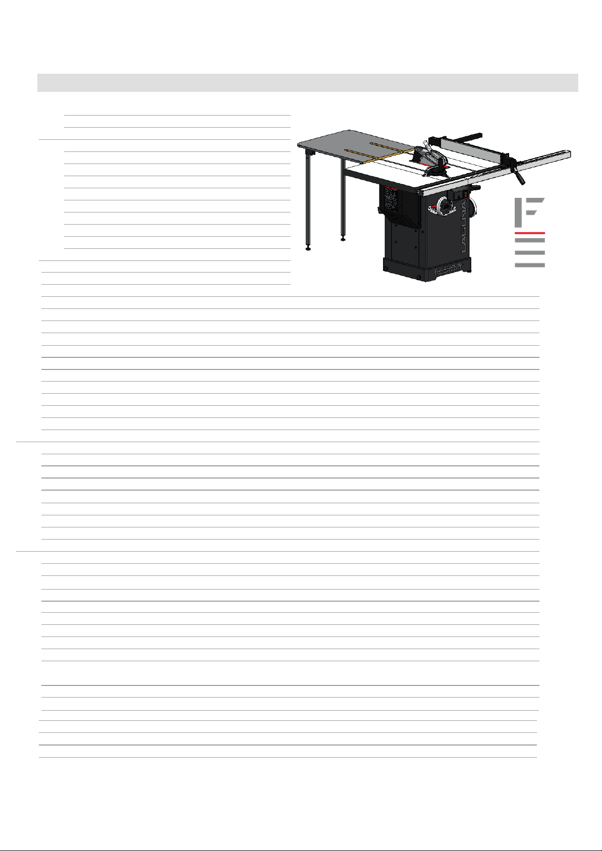
Specifications
-1
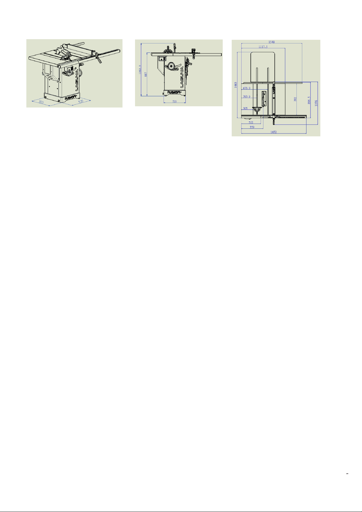
Foot Print (LxW) 503 x 520 mm
Overall Dim
Shipping Dimensions (LxWxH) 870 x 1190 x 1085 mm
Net Weight (No Accessories) 157Kgs
Shipping Weight 202 Kgs
Dust Collection: Outlet Dia. 101.6 mm
Dust Collection: m3/h Min. Req. 934 m3/h
Sound Emissions N/A
Blade Diameter 250 mm
Bore Diameter Of The Saw Blade 30 mm
Arbor Speed 3800 /min
Blade Rotation Count-Clockwise (Face arbor)
Rip Capacity, with Fence 914.4 mm Right, 431.8 mm Left (1,320.8 mm option)
Maximum Depth of Cut @ 90° 79mm
Maximum Depth of Cut @ 45° 56mm
Blade Tilt 45° Left, 3° Arbor Adjustment
Table Dimension, with Extensions 1117.5mm x 1663mm
(LxWxth.)
Extension Wing Dimension (LxW) 792 x 305 mm
Mitre Slot 19 to 23 mm T-slot
Fence Type Sliding Cam Action Fully Adjustable
Fence Face Dimensions (LxWxth.) 670 x 80 x 17 mm
Throat Plate Type Professional Square Zero Clearance
Throat Plate Dimensions (LxWxth.) 372 x 104.5 x 13 mm
Floor to Table Height 887 mm
ensions (LxWxH) 1750 x 1652 x 1080.9 mm
-1
4
Page 5
5
© 09/2019, Laguna Tools, Inc.
Fusion Tablesaw
TOP 10
Newly designed precision arbor mounted directly to cabinet top.
Height adjustment moves straight up easily with mechanical assist.
Arbor tilt
The new Laguna Arbor is Sturdy and built to
Perfectly flat and precision ground mirror finished
Designed for industrial use.
The Fusion F3 features an industrial strength 3HP motor, increased thickness cabinet, and an electromagnetic
Quick release blade guard
Quick Arbor Adjustments with the 2:1 assisted tilt mechanism and mechanically assisted height
Quick blade change
is
FEATURES
now on 2:1 ratio gear box.
attachments.
last.
tabletop.
adjustments.
starter
for industrial
use.
5
Page 6

SAFETY
The following is a list of safety precautions you must consider when using a Table saw:
ALWAYS REMEMBER TO DISCONNECT THE POWER
TO THE TABLE SAW WHEN MAKING REPAIRS OR
ADJUSTING BLADES AND GUARDS.
• Eye and ear protection are required when operating a Table
saw. Dust extraction & respiratory PPE are highly recommended.
• Do not wear gloves, loose clothing, jewellery, or any
dangling objects when operating a Table saw.
• Do not allow children to operate the machine.
• At all times all guards must be in place and fully
operational. If a guard seems to be missing or
damaged, adjust, replace or repair immediately.
• A riving knife MUST be used at all times when
performing through cuts and must be positioned
correctly.
• Ensure that the Rip fence is correctly aligned to the blade to
help prevent the risk of timber kick back.
• Never perform “free hand” cuts, a rip fence or mitre
cross cut fence should always be used.
• Never pull the timber through the blade from the rear
of the machine, always push through from the front.
• Disconnect the power to the Table saw when making repairs or
adjusting blades and guards.
• Hands and fingers must be kept clear of the blade,
always use push sticks when feeding smaller pieces into the
blade.
• Use only the recommended blade size and type for the ma
chine - see page (20) for recommendations.
• Ensure all blades are sharp and in good condition.
• Never cut pieces smaller than the table insert size.
• Long material should be supported at the same height
as the saw table.
• To avoid contact with a coasting blade, do not reach into the
cutting area until the blade comes to a full stop.
• Make sure the blade is not in contact with the material when
you start the saw.
• Never leave the machine unattended when it is running.
•Keep the table top & surrounding work area free from excessive
dust and debris to help prevent slipping or
tripping.
• Maintain a balanced stance at all times so that you do not fall
or lean against the blade or other moving parts. Do not over
reach or use excessive force to perform any machine operation.
-
-
ALWAYS REMEMBER TO READ
THROUGH THE MACHINE INSTRUCTIONS SUPPLIED.
Kickback
• The most common accidents among table saw users,
according to statistics, can be linked to kickback, the high-speed
ejection of timber from the table saw that
can strike the operator. Kickback can also result in the operator’s
hands making contact with the blade.
Kickback Prevention
• Tips to avoid the most common causes of kickback:
• Make sure the riving knife is always aligned with the blade. A
workpiece can bind or stop the flow of the cut
if the riving knife is misaligned, and result in kickback.
• Use a riving knife during every cut. The riving knife
maintains the kerf in the workpiece, which will reduce
the chance of kickback.
• Never attempt freehand cuts.
• The workpiece must be fed parallel to the blade,
otherwise kickback will likely occur. Always use the rip fence or
mitre gauge to support the workpiece.
• Make sure that the rip fence is parallel to the blade. If not, the
chances of kickback are very high. Take the time to check and
adjust the rip fence.
• Feed cuts through to completion. Anytime you stop feeding a
workpiece that is in the middle of a cut, the chance of binding,
resulting in kickback, is greatly increased.
Tips for Kickback Protection
Kickback can happen even if precautions are taken to prevent it.
Listed below are some tips to protect you if kickback does occur:
• Stand to the side of the blade when cutting. An ejected work
piece usually travels directly in front of the blade.
• Wear safety glasses or a face shield. Your eyes and face are the
most vulnerable part of your body.
• Never place your hand behind the blade & never pull the tim
ber through the cut. If kickback occurs, your hand will be pulled
into the blade.
• Use a push stick to keep your hands further away from the
moving blade. If a kickback occurs, the push stick will most likely
take the damage that your hand would have received.
-
-
More safety information can be found at: http://www.hse.gov.uk/pubns/wis16.pdf
6
Page 7
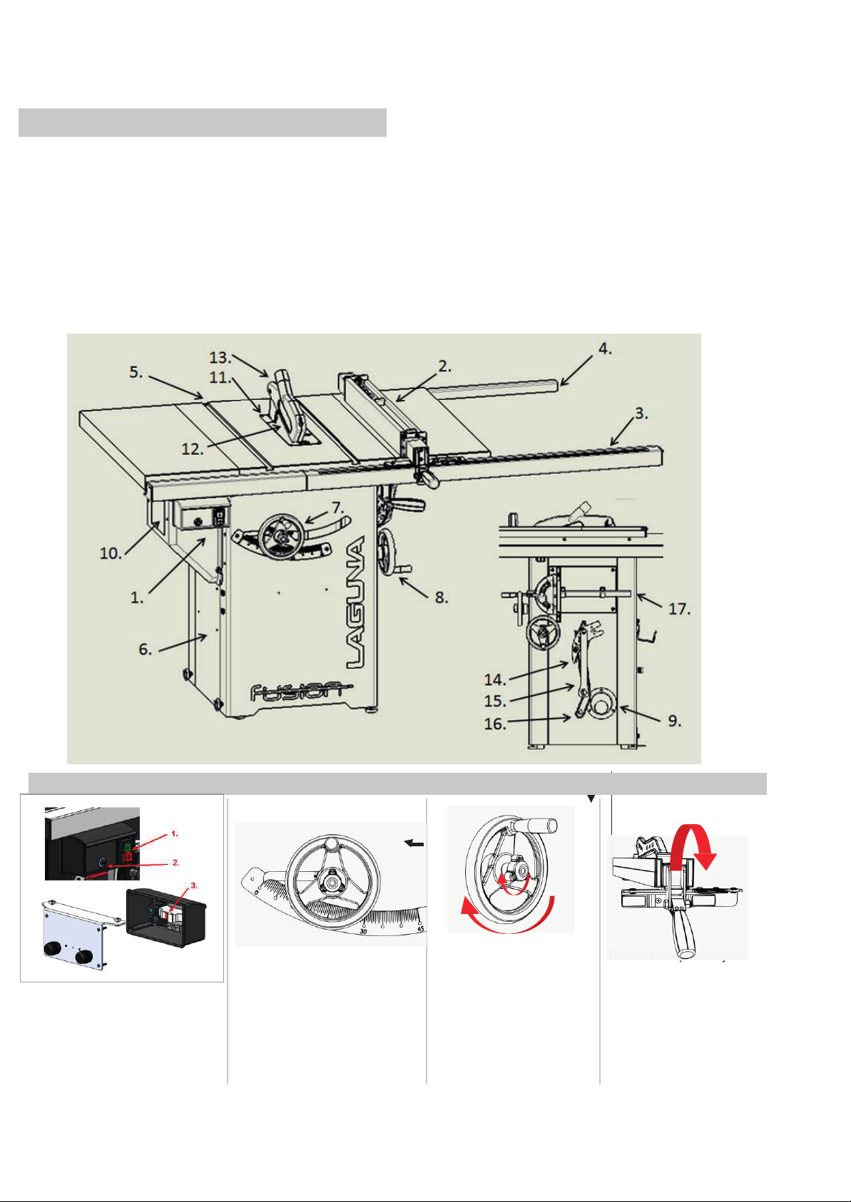
Fusion Tablesaw
1.
Start/Stop Control Switch
6.
Cabinet with integrated mobility kit
12.
Blade
2.
Rip Fence
7.
Arbor Height adjustment control
13.
Blade Guard
3.
Fence Front Guide
8.
Arbor Tilt adjustment control
14.
Riving Knife
4.
Fence Rear Guide
9.
Dust Extraction outlet.
15.
Arbor Wrench
5.
Table with Miter Slots
10.
Motor Cover
16.
Push Stick
11.
Throat plate
17.
Miter Gauge
Tool Overview
Your new Laguna Tools machine is comprised of different components to make a long lasting and precise piece of machinery that will help you
with your next project. Understanding your new machine and its components will make you a better craftsman.
The basic components of the table saw are:
Controls
``
1. Magnetic Switch
2. Overload Protector
3. Fuse
CAUTION: ALWAYS TURN OFF AND
UNPLUG THE MACHINE BEFORE
CHANGING THE FUSE
Start/Stop/Fuse
Arbor Height Control & Tilt
The arbor height control adjusts the
height of the blade. Centered in the
control is the height adjustment lock.
Behind the control is the tile gauge.
CW to raise, CCW to lower blade.
CAUTION: DO NOT ADJUST HEIGHT
WHEEL WHEN LOCKED.
gauge
Arbor Tilt
The tilt control, located on the
right of the cabinet, adjusts the tilt
of the arbor. Center is the tilt lock.
CW to tilt left, CCW to tilt the
blade to the right. CAUTIO
NOT ADJUST TILT WHEEL
WHEN LOCKED.
control
N: DO
`
Fence clamp
The fence clamp securely locks
the fence anywhere on the rail
by a cam action mechanism.
lock
15
7
Page 8
Fusion Tablesaw
Fig.1
NOTICE:
For safety reasons, this machine is not sold with a tape-rule for the left side of the blade. It is not a missing part.
Notice:
number is comprised of two pieces – long and short.
Setup
Receiving and Unpacking
Use
Caution: Your new Laguna Tools machine is heavy. Use a
minimum of two people when lifting the tool into position and moving
the tool into position.
Tech
Tip: A setup video is available at
lagunatools.com/classic-machinery/tablesaws/f2-fusion/
or www.youtube.com/watch?v=FOPstZ61uFs
warning: To avoid set-up problems, to prevent potential damage
to the machine and personal injury, read through the entire setup
section prior to setting up the machine.
warning: DO NOT connect to a power supply until the setup is
complete. DO NOT perform any of the following steps, installations,
or adjustments with the saw connected to the power source.
If any damage has occurred because of shipment, note the damage on the bill of lading or refuse the shipment. Immediately call the dealer store
where the machine was purchased
TRANSPORTATION AND STORE The measures of anti-rust and shockproof should be taken during packing. The machine endures transportation
and store in -25~55°C ambient temperature.
Be care of not making machine exposed to rain or damaging the packing during transportation and store.
While transporting or handling the machine, be careful and let the activity be done by qualified personnel especially trained for this kind of activity!
While the machine is being loaded or unloaded, make sure that no person or subject gets pressed by the machine!
Select proper transportation device according to the weight of the machine.
Make sure the lifting capacity of transportation device is competent for the weight of the machine.
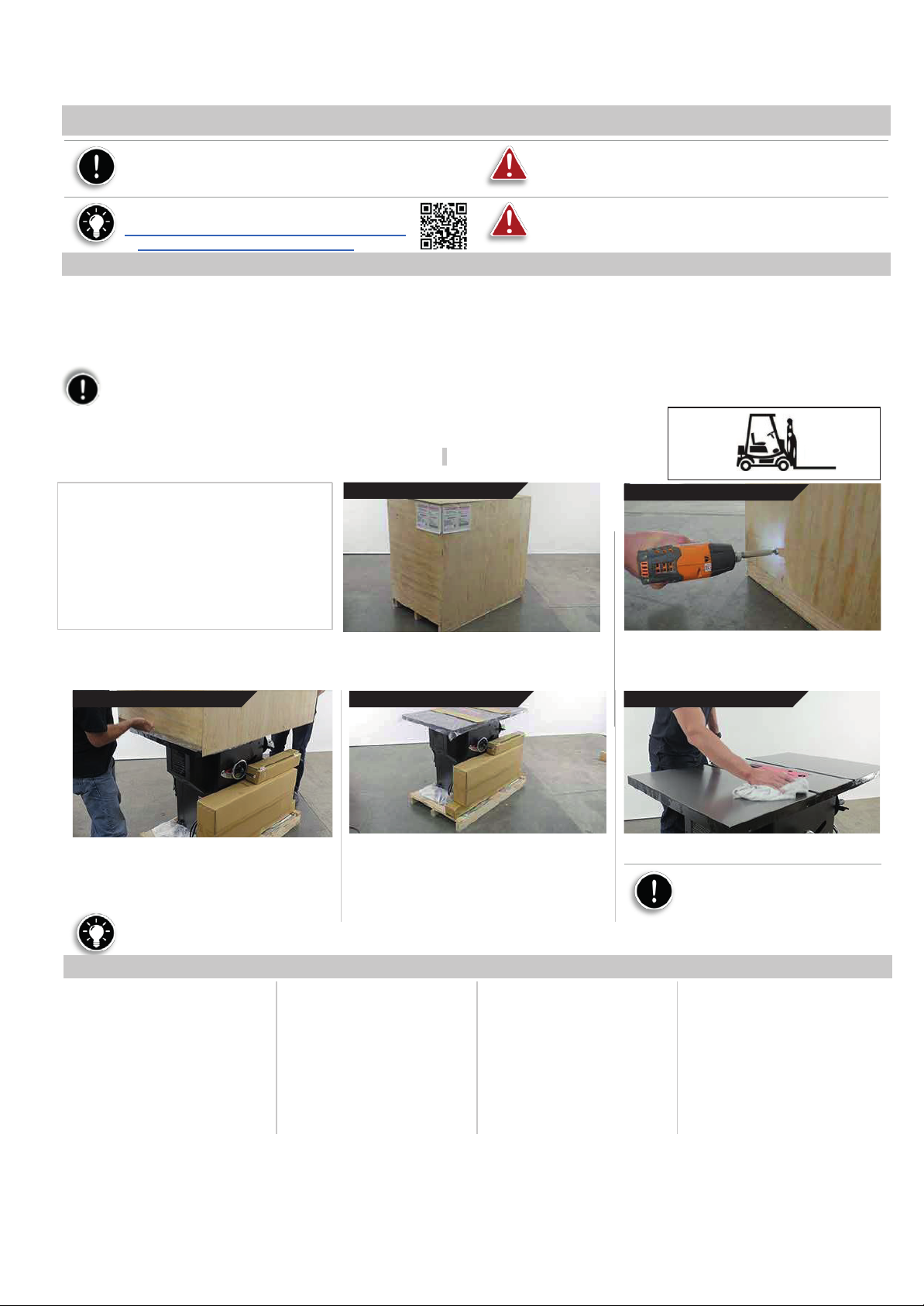
TRANSPORTATION BEFORE UNPACKING As standard, the machine is packed in a robust wooden
box. Fig.1 shows the tool can be used to transport the packing box.
UNPACKING
1. Receiving your tablesaw.
2. Unscrew the crate fasteners.
3. Lift crate off pallet.
4. Check Inventory.
5. Wipe off protective oils.
Unscrew the crate
fasteners
Use a drill or screw driver with a #2 Phillips head
bit and remove the bottom screws from carton.
These screws may be discarded.
Wipe
off
protective
plastics
Lift crate
off pallet
This is how the machine is shipped from the
factory.
Check
Inventory
Use two persons to lift the carton away from the
pallet. There should be three packages along
the table saw.
NOTE: The throat plate, riving knife, and 10” blade is pre-installed in
the machine. The miter gauge, and blade changing tool are positioned
in the tool holder located on the right side of the cabinet.
Tech
Tip: To help keep your table top clean and to prevent or clean any rust, we recommend waxing your tabletop with an appropriate wax
rubbing compound. This will also reduce friction under operation. Rust can be removed with WD-40.
Inventory
Fence
Push Stick
Blade Guard
Install Tools
Fence Hooks*
*Fence storage hooks may be pre-installed.
Box
1 contents
PTSF236110175-0130-1-1
PTSF236110175-0130-130
PTSF236110175-0130-2-1
-
PTSF236110175-0130-118
The front rail part number is comprised of two pieces – both long and short. The rear rail part
with
Rear Rail 2
Front Rail 2
Hardware kit
1. Fence, install tools, push stick, blade
guard assembly
2. Smaller fence rail sections, hardware kit
3. Longer fence rail sections.
Box
2 contents
PTSF236110175-0130-127.5
PTSF236110175-0130-127.6
-
Rear Rail 1
Front Rail 1
Box
3 contents
PTSF236110175-0130-127.5
PTSF236110175-0130-127.6
Peel back the protective vinyl plastic and wipe
away the oil with a waste rag.
Use
Caution: An oily rag can
be a serious fire hazard. Discard
in an appropriate manner.
Pre-Installed
Throat Plate
Riving Knife
10” Blade
Miter Gauge
Arbor Wrench
Tool Storage
Wing (2)
on machine
PTSF236110175-0130- 6
PTSF236110175-0130- 27
PTSF236110175-0130- 33
PTSF236110175-0130- 3
PTSF236110175-0130- 137
PTSF236110175-0130- 120
PTSF2 36110175-0130-4
16
8
Page 9
Fusion Tablesaw
17
Loose Parts & Overview
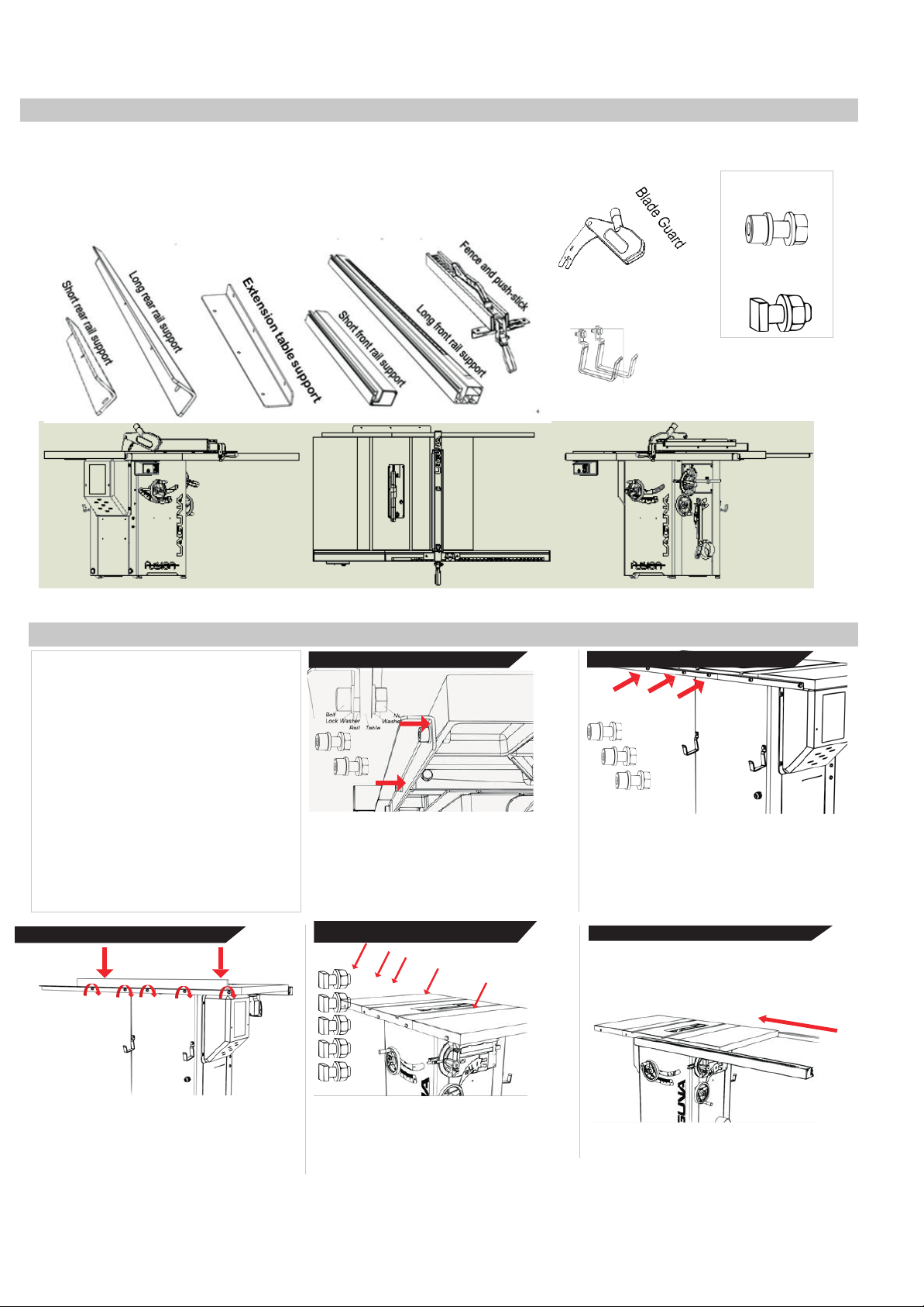
To level the rear fence with the table
Insert the long Front Rail. STOP
Your new machine has been mostly assembled at the certified ISO 91001 factory where it was made. Some parts must be assembled by
the purchaser. Please read all steps first before proceeding with step one.
(5) M8x1.5+ lock washer
+ washer +nut
(5) Square Head
8x1.5+ washer +nut
12.
[See explanation of steps on the following pages.]
General Setup
1. Attach the short rear fence support
2. Attach the long rear fence support
3. Level the rear rails and fasten
4. Attach T-Slot bolts to front table
5. Insert long front rail fence support
6. Insert short front rail and switch
7. Join front fence supports
8. Align the entire front rail to blade mark
9. Level and fasten the front rail
10. Insert fence
11. Level the saw by adjusting casters
1.
10.
6. 7. 8.
9.
1.
Attach short rear fence
Use the supplied wrench and Alan key to loosely
fasten (2) bolts, lock washers, washers, and nuts
to the short rear fence guide and the back left of
the table. STOP BEFORE TIGHTENING: Keep
bolts loose until entir
properly level rail.
3.
2.
4.
11. 5.
support 2.
e rail assembly is in place to
Fence hooks (step
2)
Attach long rear fence
Repeat step 1 for the longer rear fence section with
(3) bolts, lock washers, washers, and nuts. Use the
same assembly diagram in Step 1.
NOTICE: If the fence hooks are not yet installed,
now is a good time to do so.
support
3.
Level the rear rails and
top, place a rigid straight edge on top of
the rails. Apply downward force at both
arrow indicators and simultaneously
tighten the bolts with the supplied Allen
key and wrench.
fasten
4.
Attach T-slot bolts
Loosely fasten the (5) square headed bolts,
(5) washers, and (5) nuts. A couple
revolutions of the bolt will be tight enough.
Prepare to insert the (2) aluminum front rail
sections.
to
front
9
table
5.
Insert the long front fence
BEFORE TIGHTENING: Keep these
bolts loose until the entire rail assembly
is in place to properly level the rail.
support
Page 10
Fusion Tablesaw
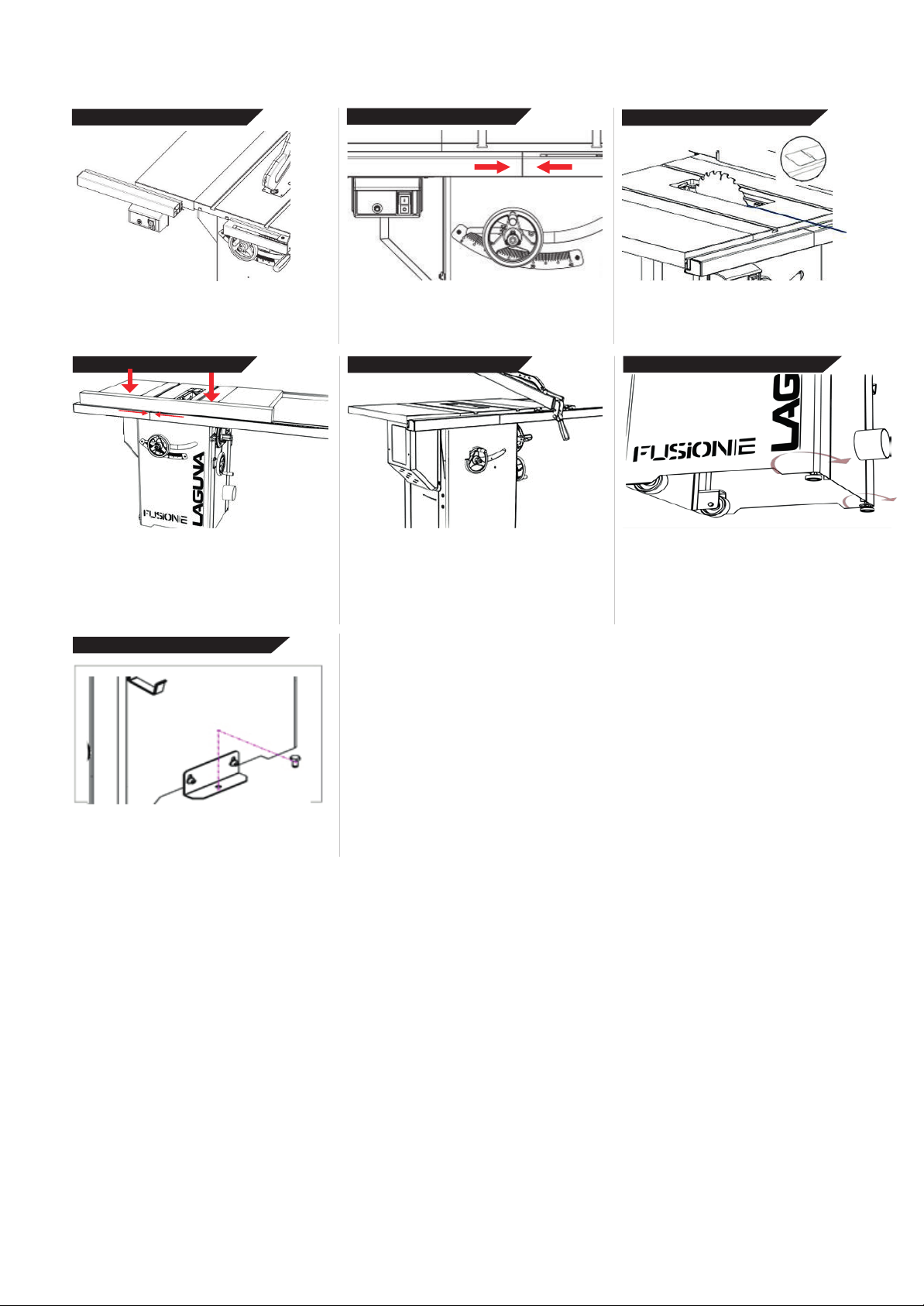
6.
Adjust lock plate location and fix the machine on the
f
Insert short rail and
switch 7.
Join front fence
supports 8.
Align the front rail with
blade
Insert the short front rail into the first square head
bolt. IMPORTANT: Insert the switch assembly
before joining the two front rail pieces. STOP
BEFORE TIGHTENING.
9.
Level and fasten front
This step may take 2 persons. To level the front
rail sections to the table top, use a ridged straight
edge atop the loosely fit rail sections. Apply
downward force to the straight edge while keeping
the two sections firmly together. Simultaneously
fasten down the bolts.
rail 11.
12. Fix the machine to the floor
Align the pins and join the two front rail pieces and
firmly push together.
10.
Install the
Install the fence by placing the front end first. Be
sure that the handle is in the open, unlocked,
position prior to installing.
fence
Using the blade notching on the measuring tape,
align the entire front rail section to the blade.
Level the tablesaw with
To level the tablesaw with the ground, use the two
leveling casters. The knobs on the left lock the
mobility of the saw.
casters
If required you can fix the machine to the floor
using the transport brackets
loor by screw.
10
Page 11
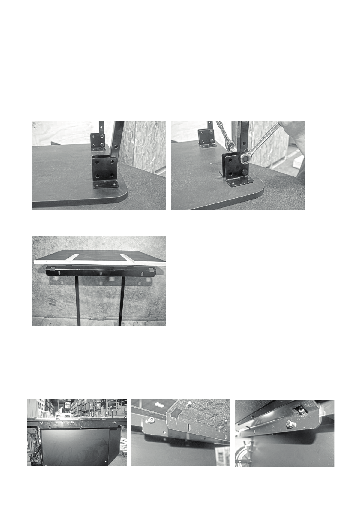
Rear Extension
Table
The Fusion F1 table saw’s rear extension table supports both the fence and the work piece. In conjunction with the rear rail,
the rear extension table provides an extra support table for the length of the wood piece being cut.
Quick Reference Guide
Add. Required Tools:
Level
General Wrench
17mm socket wrench (optional)
Troubleshooting/Tips:
For easiest assembly, flip the rear extension table so that the
face is down. After the table has been flipped, attach the rear
extension legs to the table.
Parts
REF
Description
Q Installation
Rear Extension Table
1
Rear Rail Assembly, F1 Table
Rear Extension Table Legs
2
Rear Extension Table
Hardware
REF
Description
Q Installation
C
Hex Cap Screw w/ Flat Washer
(longer)
3 of 5
Rear Extension Table, F1 Table
I
Hex Cap Bolt (51mm)
use with Nylon Lock Nuts(H)
4 of 4
Rear Extension Table Legs,
Rear Extension table
J
Nylon Lock Nuts (16mm)
4 of 4
Rear Extension Table Legs,
Rear Extension table
Attaching Legs to the Rear Extension Table:
aligned with the last two bolt holes of the metal bracket.
4.
Thread the 51 mm hex bolts through the metal L-bracket.
Pre-
installation
Aligning the bracket
1.
Flip the rear extension table so that the face is down.
2.
Place the rear extension legs between the metal L-brackets on either side of the table.
3.
Align the rear extension leg’s bolt holes with bracket’s bolt holes. Ensure that the rear extension leg’s bolt holes are
5.
Thread nylon lock nuts on to the back of the hex bolts. Tighten with a wrench or a 17 mm socket wrench (optional).
Attaching legs to table:
Installed
Legs
Securing
Bolts
Attaching the Rear Extension Table to the Table Saw:
1.
Locate the three through holes on the back mounting bracket of the rear extension table.
2.
Align these three through holes with the three threaded holes on the rear support bracket.
3.
Thread one of the three (longer) Hex Bolt with Flat Washer through each of the threaded holes.
NOTICE! The height of the rear extension table’s legs can be adjusted as needed to level the table.
Pre-
installation
Aligning the bracket
Bolt into thread holes:
11
Page 12
Pre-
installation
Aligning the bracket
Bolt into thread holes:
Fusion Tablesaw
6.
Insert short rail and
switch 7.
Join front fence
supports 8.
Align the front rail with
blade
Insert the short front rail into the first square head
bolt. IMPORTANT: Insert the switch assembly
before joining the two front rail pieces. STOP
BEFORE TIGHTENING.
Align the pins and join the two front rail pieces and
firmly push together.
Using the blade notching on the measuring tape,
align the entire front rail section to the blade.
9.
Level and fasten front
rail 11.
Level the tablesaw with
casters
This step may take 2 persons. To level the front
rail sections to the table top, use a ridged straight
edge atop the loosely fit rail sections. Apply
downward force to the straight edge while keeping
the two sections firmly together. Simultaneously
fasten down the bolts.
To level the tablesaw with the ground, use the two
leveling casters. The knobs on the left lock the
mobility of the saw.
12. Fix the machine to the floor
Adjust lock plate location and fix the machine on the
floor by screw.
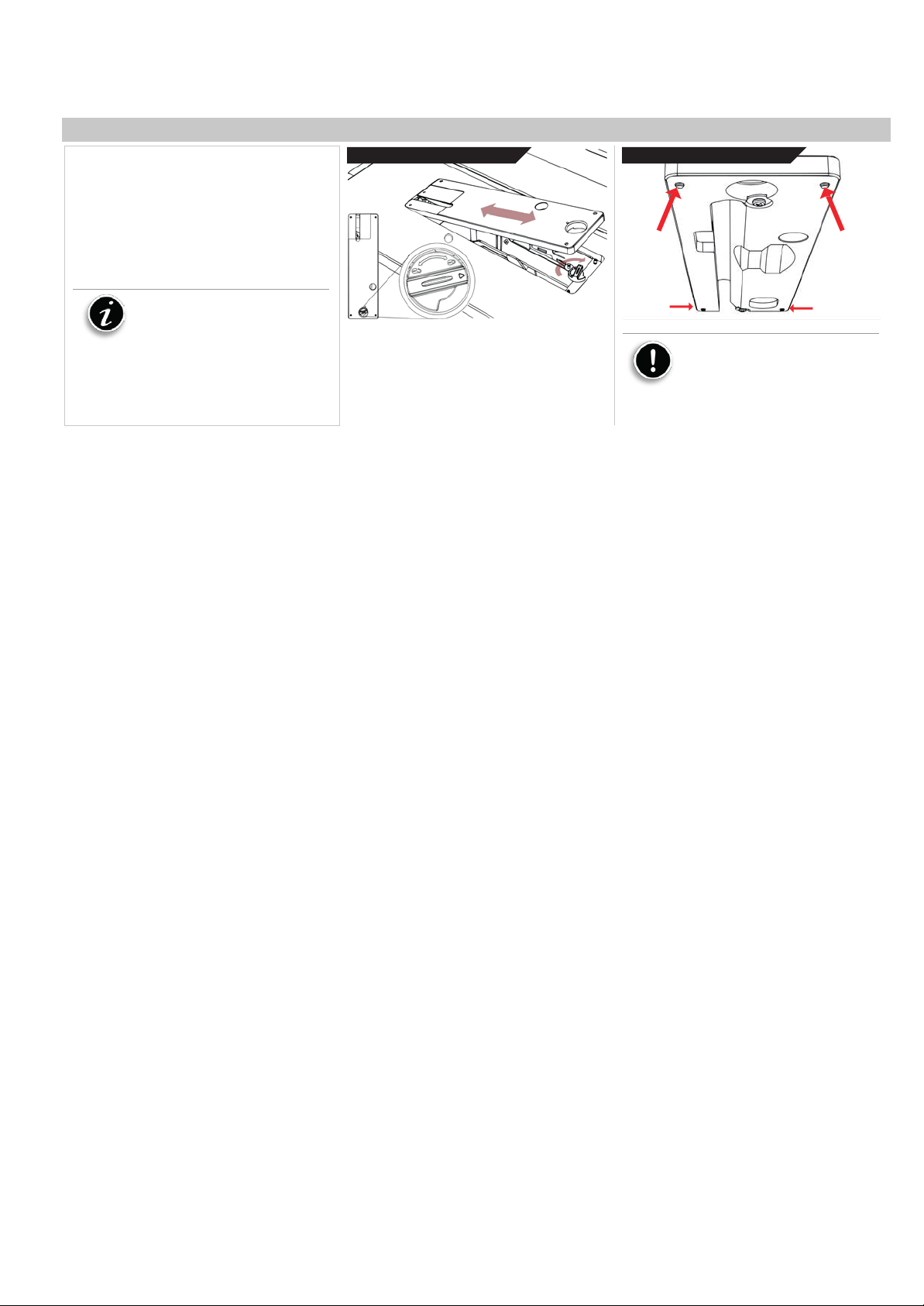
Installing/Removing the Throatplate
If required you can fix the machine to the floor
using the transport brackets
10.
Install the
fence
Install the fence by placing the front end first. Be
sure that the handle is in the open, unlocked,
position prior to installing.
1. Un-plug the tablesaw!
2. Insert the throat plate back end first.
3. Lower the throatplate to the table.
4. Lock the throat plate with the thumb-lock.
5. Level the throatplate with the table using
the cat screws.
Notice: This machine is shipped
with a zero-clearance throat plate that
has already been cut at the factory.
Because of this, there may be some
residue already in the saw.
Installing the throat
plate
WARNING: MAKE SURE SAW IS UNPLUGGED.
To remove or install the throat plate, first set it to
the unlock position. Then, insert the rear end first
and tilt the other en
d down into position.
Leveling the throat
To level the throatplate, adjust the leveling screws.
Use
Caution: Make sure the throat
plate is lower than the cast iron table.
Having the throat plate higher at any
position can interfere with the workpiece
feed and cause injury or harm and
increase the chance of kickback.
plate
12
Page 13
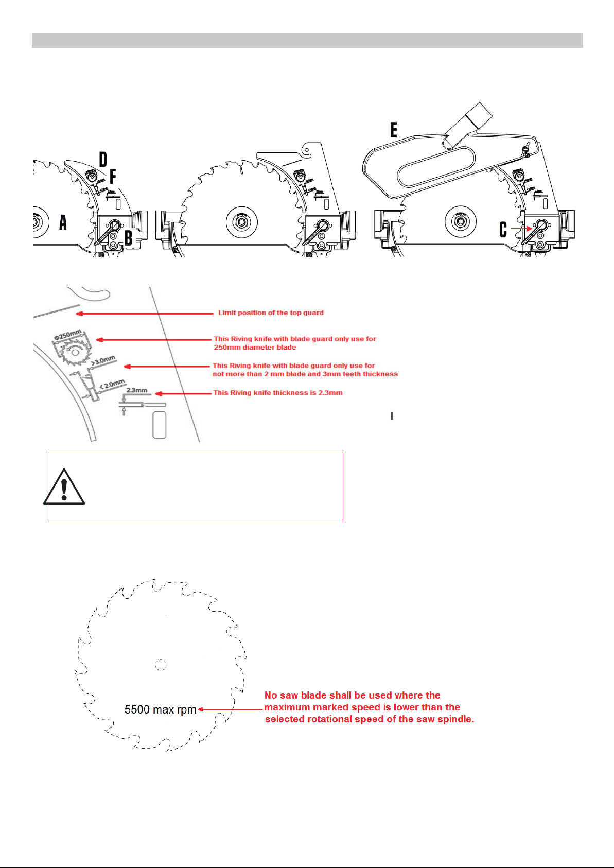
Fusion Tablesaw
Installing/Removing Safety Accessories
⚫
Fusion Tablesaw
Warning: Since Riving Knife, other than those offered by Laguna, has not been tested with this product, use
of such accessories with this tool could be hazardous. To reduce the risk of injury, only Laguna,
recommended accessories should be used with this product.
Installing/Removing Safety Accessories
A: Saw
blade
B: Accessory insert
block
C: Cam action
lever
D: Riving
knife
E:
Blade
Guard
F:
Blade Compliant
Markings
⚫ Note on the Riving Knife
⚫
A: Saw
blade
block
B: Accessory insert
C: Cam action
lever
Note on the Riving Knife
D: Riving
E:
Blade
Blade Compliant
F:
knife
Guard
Markings
Warning: Since Riving Knife, other than those offered
by Laguna, has not been tested with this product, use
of such accessories with this tool could be hazardous.
To reduce the risk of injury, only Laguna, recommended
accessories should be used with this product.
Note on the Blade
13
Page 14
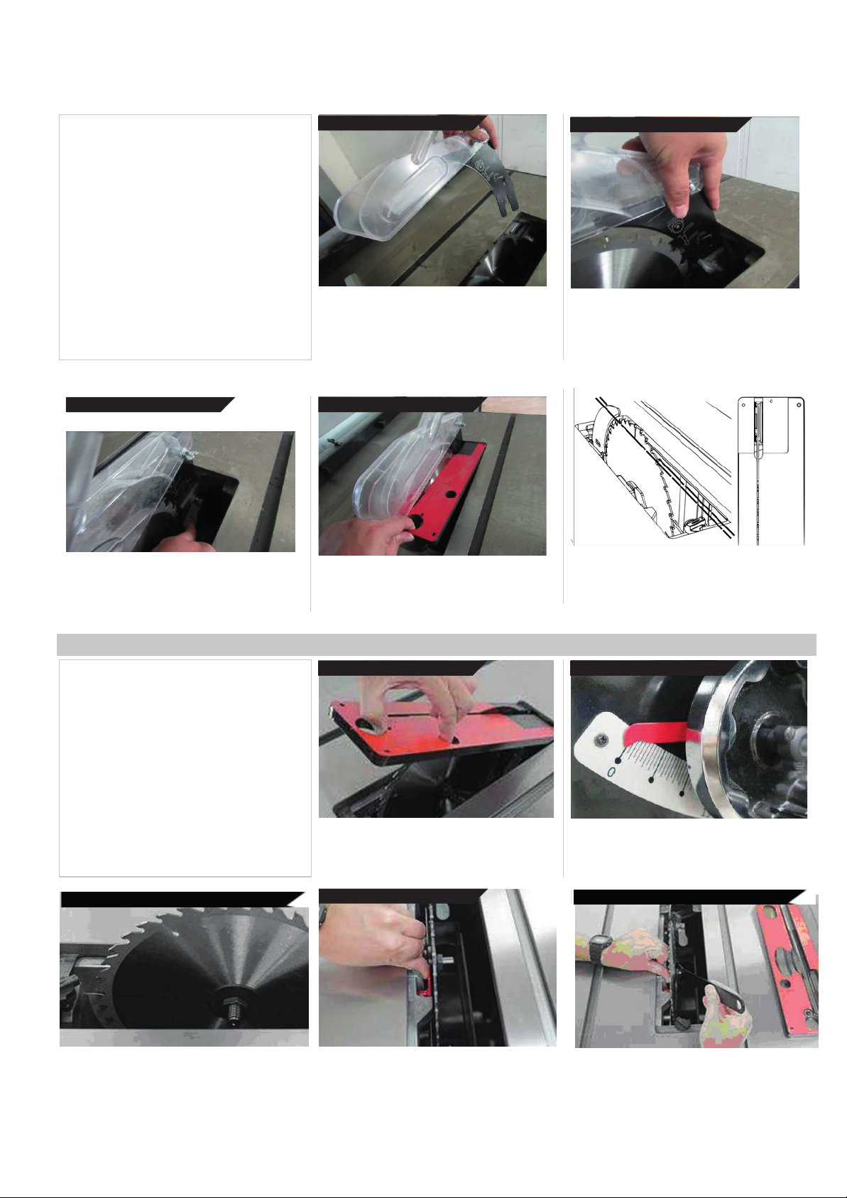
Fusion Tablesaw
Installing/Removing the Blade
Guard
1. Un-plug the tablesaw!
2. Make sure the lock is in open position
3. Insert the blade guard
4. Position the guard insert
5. Lock the blade guard
6. Reinstall throat plate
CAUTION: Make sure the blade guard is inline with the blade. If it is not in line, please
see the Adjustments Section.
3.
insert the blade
WARNING: MAKE SURE SAW IS UNPLUGGED.
With the throat plate removed, and the cam lock
mechanism in the open position (pulled up), insert
the blade guard insert into the slot.
guard 4.
position
Hold up the pawls and position the blade guard
against the left inside of the casing and push down.
Slide the riving knife against the left inside
Make sure the guard is positioned correctly and
of the casing and push down. Make sure the
guard is positioned correctly and seated in
seated in the bottom of the casing. Grasp the
the bottom of the casing.
pawls with one
to activate the cam action lock.
TO
LEFT
OF CASING
hand, leaving the other hand free
5.
lock THE Blade
Keep firm hold of the blade guard with left hand
and engage the cam lock with the thumb of your
right hand.
Guard 6.
Installing/Removing the Blade
1. Un-plug the tablesaw!
2. Remove any blade guards, riving knifes,
splitters, and the throat plate to access the
blade.
3. Set the arbor tilt to 0 degrees and lock.
4. Raise saw to highest position.
5. Engage blade lock (red component).
6. Remove the arbor nut and flange with
arbor wrench.
7. Remove or install blade.
CAUTION: Make sure the teeth of the blade
are facing the front of the saw as shown.
Reinstall the throat
Grasp the pawls up and out of the way to re-insert
the throat plate. Lock the throat plate.
Reinstall and lock the throat plate
2.
Remove
WARNING: MAKE SURE SAW IS UNPLUGGED.
To access the blade remove all accessories
around the blade, including riving knifes, throat
plates, ect.
all accessories 3.
plate
CAUTION: Make sure the riving knife is in-line with
the blade. If it is not in line, please see the
Adjustments Section.
Set arbor tilt
Set the arbor tilt to 0 degrees and lock the arbor to
prevent it from moving when installing or removing
blades.
to 0
and
lock.
4.
4.Raise Sawblade to highest position
highest
Raise saw blade
pos.
to
5.
Engage the blade
14
lock
6. Remove arbour nut and flange
6.
Remove arbor nut and
flange
Page 15
Fusion Tablesaw
21
Adjustments
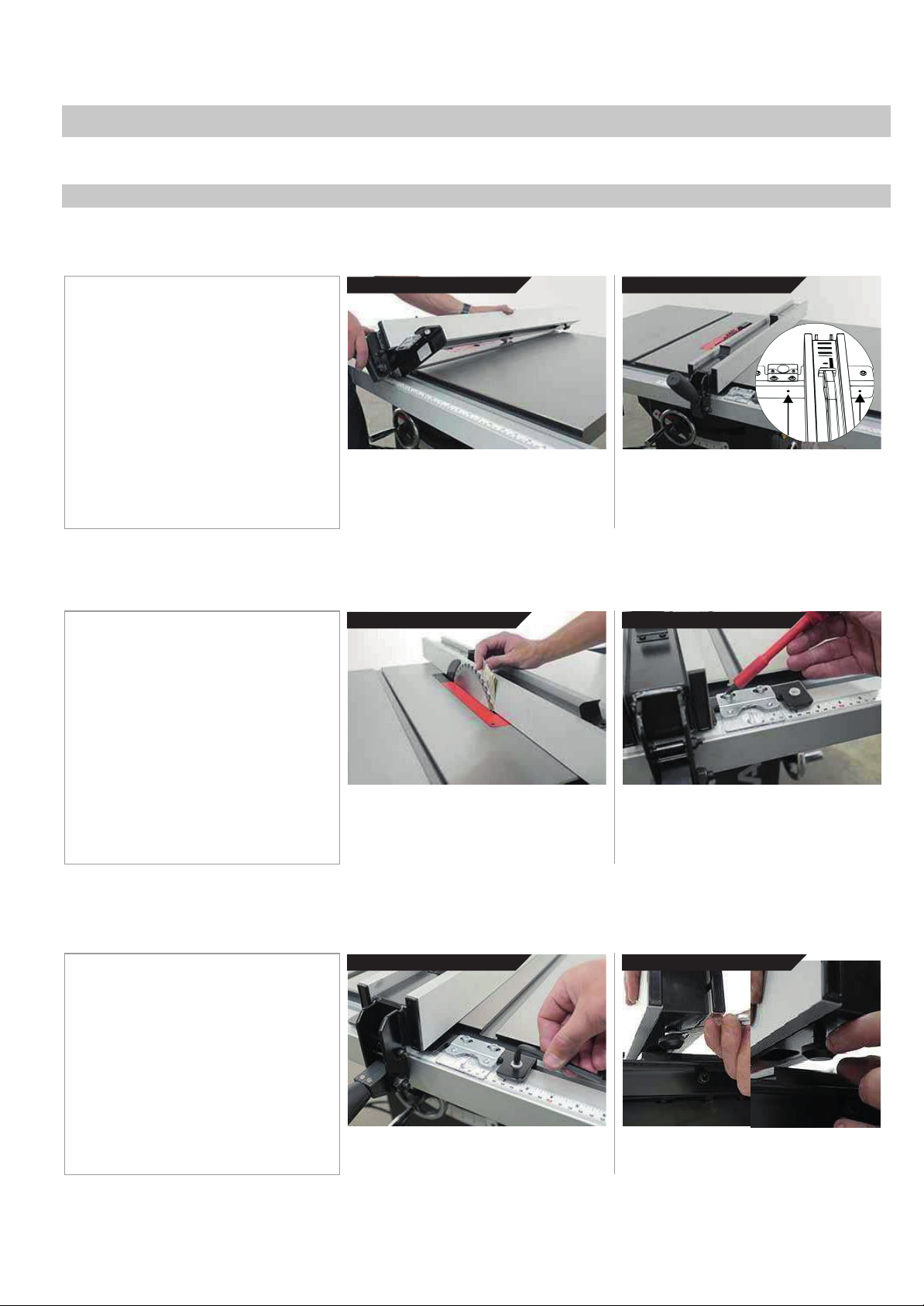
To adjust the front bushings, use the
To adjust the rear bushing, loosen the
tighten the hex nut.
Your Laguna Tools machine comes fully adjusted from the factory, but it is good practice to double check these adjustments and make sure the
tool is in safe operating condition.
Fence Adjustments
Fitting the
You will need to fit the fence to the right side of the blade to use the table saw. In the fit position, the fence can move freely with limited friction due
to the installed nylon and plastic glide bushings. The fence should not, at any times be used on the left side of the blade.
1. Un-plug the tablesaw!
2. Hold fence with both hands, with cam
3. Place fence in fence guide
4. Check cam lock action, adjust if
fence:
lock up.
necessary.
2.
Place fence
in
fence
guide 3.
Check Cam lock
action
Adjusting the Scale
(rule):
While holding the fence and the cam lock, raise
the cam lock to engage the open position. Insert
the fence frame into the front rail.
The fence can slide freely in any position to
right of the blade. If the fence does not lock, adjust
both blade paralleling set screws (located on the
back of the fence frame as shown) at the same
rate, as needed.
the
The scale will need to be “zeroed” every time the fence guide is taken off the table or adjusted. The fence must be zeroed for accurate cuts when
using the scale.
Place fence
in
fence
guide
Adjust the
Viewport
1. Un-plug the tablesaw!
2. Position the fence up to blade.
3. Loosen the transparent viewport.
4. Adjust the view as needed
5. Tighten the view screws.
Adjusting
the
Fence Glide
Bushings:
WARNING: MAKE SURE SAW IS UNPLUGGED.
With the blade in a high position, bring the fence
close to — but not touch
folded piece of paper between the blade and the
fence to ensure good distance.
ing — the blade. Use a
Use a #2 Philips head driver to loosen (but do not
remove) the transparent scale reader. Adjust the
viewport as needed, tighten the screws. NOTICE:
If adjusting the viewport does not allow enough to
zero the scale, see step 8 of general setup.
You may need to adjust the height of the bushings on either side or rear of the fence. The fence should be between 1/16” and 1/8” off the table to
prevent scratches and not to allow any thin stock to slip through.
Front
Bushings
Rear
Bushings
1. Un-plug the tablesaw!
2. Unlock the fence.
3. Use a hex key to adjust the front
bushing height.
4. Use a wrench to adjust the rear bushing
height.
included hex key to raise or lower the
nylon bushings that make contact with
the front fence rail.
15
hex nut that locks the height position of
the bushing. Adjust the position and
Page 16
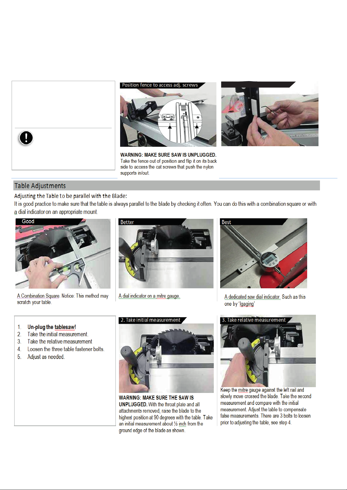
Fusion Tablesaw
Adjusting
of the blade as shown.
prior to adjusting the table, see step 4.
Good
A dedicated saw dial indicator. Such as this
the
Fence
to be
Parallel with the
Blade:
It is very important to only operated this saw with the blade parallel to the fence. NOTICE: If this section does not help, please see the table
adjustments section: Adjusting the Table to be Parallel with the Blade. The blade needs to be parallel to the table (mitre slots) to effectively make
the fence parallel to the blade.
Position fence
to
access adj.
screws
Use a hex key
to adjust
1. Un-plug the tablesaw!
2. Position the fence to access the fence
adjustment screws.
3. Use a hex key to adjust each side
4. Make small increments and check
Use
Caution: It is not guaranteed
that the fence will be parallel to the saw
blade when shipped from factory. Make
e to make all required adjustments
sur
to make the fence parallel to the saw
blade prior to operation.
WARNING: MAKE SURE SAW IS UNPLUGGED.
Take the fence out of position and flip it on its back
side to access the cat screws that push the nylon
supports in/out.
Use the included hex key to adjust the depth of
each nylon support. Do small increments and
check.
Table Adjustments
Adjusting the Table
It is good practice to make sure that the table is always parallel to the blade by checking it often. You can do this with a combination square or with
a dial indicator on an appropriate mount. There are several dedicated tools to do this job well like the Saw Gauge sold by WoodPeckers®.
to be
Parallel with the
Blade:
Better Best
A Combination Square. Notice: This method may
Use a combination square, be aware this may
leave scratched.
scratch your table.
1. Un-plug the tablesaw!
2. Take initial measurement.
3. Take relative measurement (second).
4. Loosen the three table fastener bolts.
5. Adjust as needed.
A dial indicator on a mitre gauge.
A dial indicator on a mitre guage.
2.
Take initial
WARNING: MAKE SURE SAW IS UNPLUGGED.
With the throat plate an
raise the blade to the highest position at 90
degrees with the table. Take an initial
measurement about ½ inch from the ground edge
measurement 3.
d all attachments removed,
A dedicated saw dial such as this one
one by ‘Igaging’
by 'Igaging'
Take relative
Keep the mitre gauge against the left rail and
slowly move crossed the blade. Take the second
measurement and compare with the initial
measurement. Adjust the table to compensate
false measurements. There are 3 bolts to loosen
measurement
16
Page 17
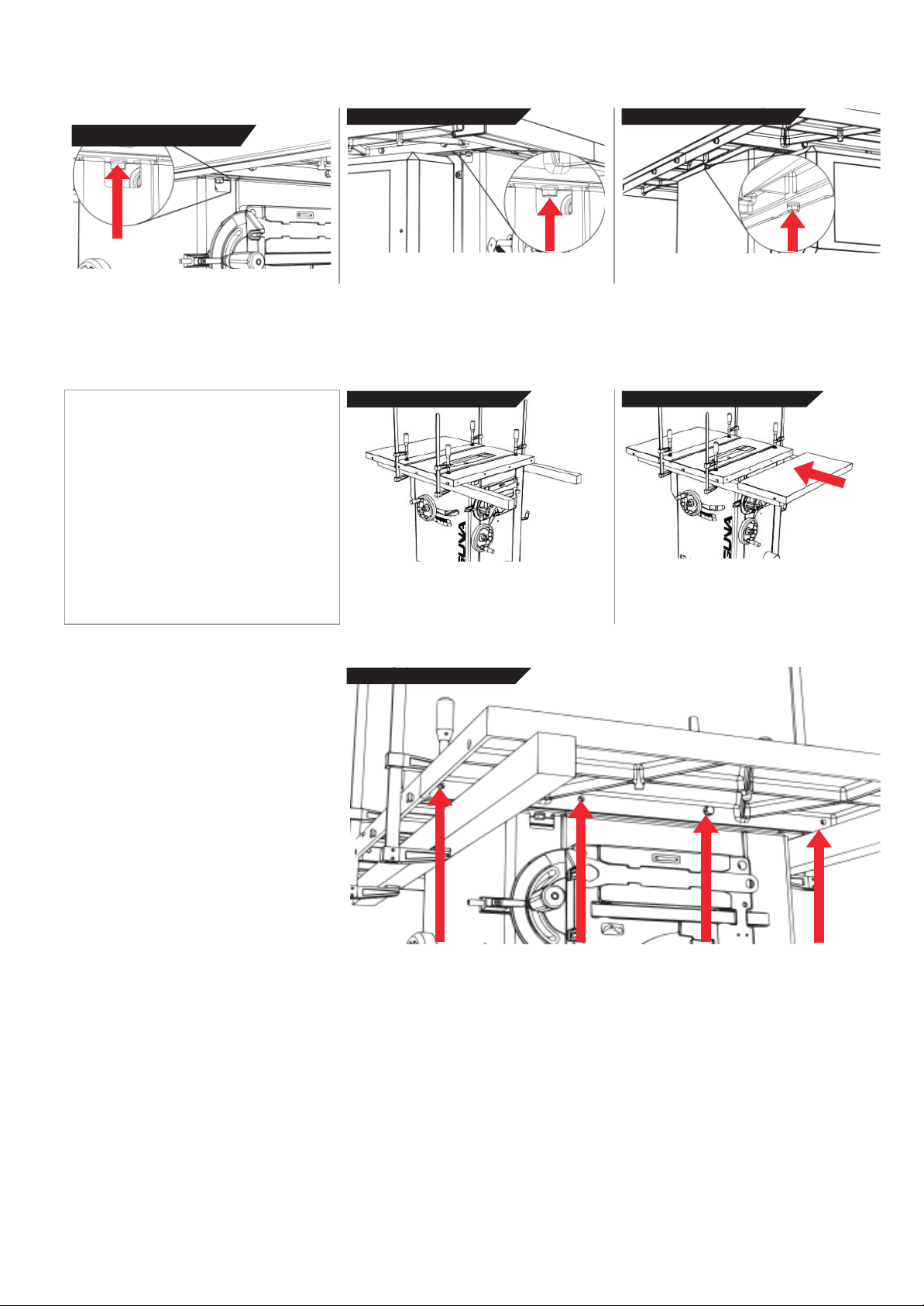
Fusion Tablesaw
23
Loosen Table
Adj
T
table
Bolts
Loosen Table
Bolts
Loosen Table
Bolts
Locate and loosen right side table to cabinet bolt
(above the tool holder).
usting
or
Installing Extension
Wings:
Locate and loosen left side table to cabinet bolt
(above the motor cover).
Locate and adjust the rear table to cabinet bolt.
o install or remove the extension wings, an advised method is provided. This method makes it easy to make the extension wings flat with the
but requires the use of two ridged supports and four clamps.
2.
Take initial
measurement 3.
Take relative
measurement
1. Un-plug the tablesaw!
2. Clamp supports to table.
3. Place extension wing on supports.
4. Join or adjust the wing with supplied
bolts.
NOTICE: The clamps may scratch the
tabletop! Use a cloth or soft wood between
the clamp and the iron surfaces.
WARNING: MAKE SURE SAW IS UNPLUGGED.
Clamp two wooden supports to the underside of
the tablesaw as shown. Straight 2x4 lumber will
work.
4.
Join
or
adjust
wing
Place the extension wing on the supports and
place into position.
You will need (4) m10 bolts and (4) washers to fasten each extension wing to the table top. Be sure to
align the extension wing to the table top prior to tightening the bolts.
17
Page 18
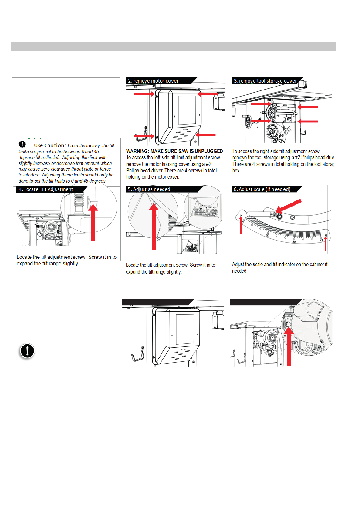
Fusion Tablesaw
Arbor and Tilt Adjustments
Use
Caution: From the factory, the tilt
Adjusting the Blade Tilt
You can check the arbor (blade) tilt limits with an angle finder or 45-degree triangle. If these limits are not within 0 degrees and 45 degrees, use
the following steps to adjust.
1. Unplug the tablesaw!
2. Remove the motor cover.
3. Remove the tool storage cover.
4. Locate tilt adjustment screws.
5. Adjust as needed.
6. Adjust the scale and indicator as
needed.
.
limits are pre-set to be between 0 and 45
degrees tilt to the left. Adjusting this limit will
slightly increase or decrease that amount which
may cause zero clearance throat plate or fence
to interfere. Adjusting these limits should only be
done to set the tilt limits to 0 and 45 degrees
4.
Locate Tilt Adjustment
screw
Limits
2.
remove motor
WARNING: MAKE SURE SAW IS UNPLUGGED.
To access the left side tilt limit adjustment screw,
remove the motor housing cover using a #2
Philips head driver. There are 4 screws in total
holding on the motor cover.
5.
Adjust as needed
cover 3.
remove tool storage
To access the right-side tilt adjustment screw,
remove the tool storage using a #2 Philips head driver.
There are 4 screws in total holding on the tool storage
box.
6.
Adjust scale
(if needed)
cover
Locate the tilt adjustment screw. Screw it in to
expand the tilt range slightly.
Adjusting the
Belt:
Locate the tilt adjustment screw. Screw it in to
expand the tilt range slightly
.
Adjust the scale and tilt indicator on the cabinet if
needed.
It is good practice to check the tension of the belt often to ensure that the saw is performing properly. If the tablesaw blade is slipping or is feeling
underpowered, you may need to tighten the belt. To do so, follow the steps below.
Remove the motor
cover
Locating Belt Adjustment
bolt
1. Unplug the tablesaw!
2. Remove the motor cover.
3. Locate belt adjustment bolt.
4. Tighten or loosen with weight of motor.
Use
Caution: DO NOT
OVERTIGHTEN BELT! The weight of
the motor is adequate to put enough
tension on the belt. Only tight enough to
prevent
slippage.
WARNING: MAKE SURE SAW IS UNPLUGGED.
To access the motor, remove the motor housing
cover using a #2 Philips head driver. There are 4
screws in total holding on the motor cover.
To adjust the belt, set blade to 0° on tilt scale, then
raise or lower blade to approximately 2" above table.
Loosen the belt adjustment bolt. With the bolt loose,
r lower the motor so that the belt is tight.
Raise o
18
Page 19
Fusion Tablesaw
Changing
the Belt
:
1. Unplug the tablesaw!
2. Remove all throatplates, blades, and
blade accessories.
3. Remove the motor cover.
4. Remove the dust shroud.
5. Loosen the Belt adjustment bolt and
loosen belt by raising motor.
6. Remove belt. NOTE: you may need to
lower the arbor height to access the
belt.
7. Replace belt.
Use
Caution: DO NOT
OVERTIGHTEN BELT! The weight of
the motor is adequate to put enough
tension on the belt. Only tight enough to
prevent slippage.
Belt Adjustment
WARNING: MAKE SURE SAW IS UNPLUGGED.
NOTICE: The drawing shown is with the top of the
table removed. AVOID removing the table top. The
belt can easily be changed without removing the
table top
bolt
Accessing the
Belt
Accessory Adjustments
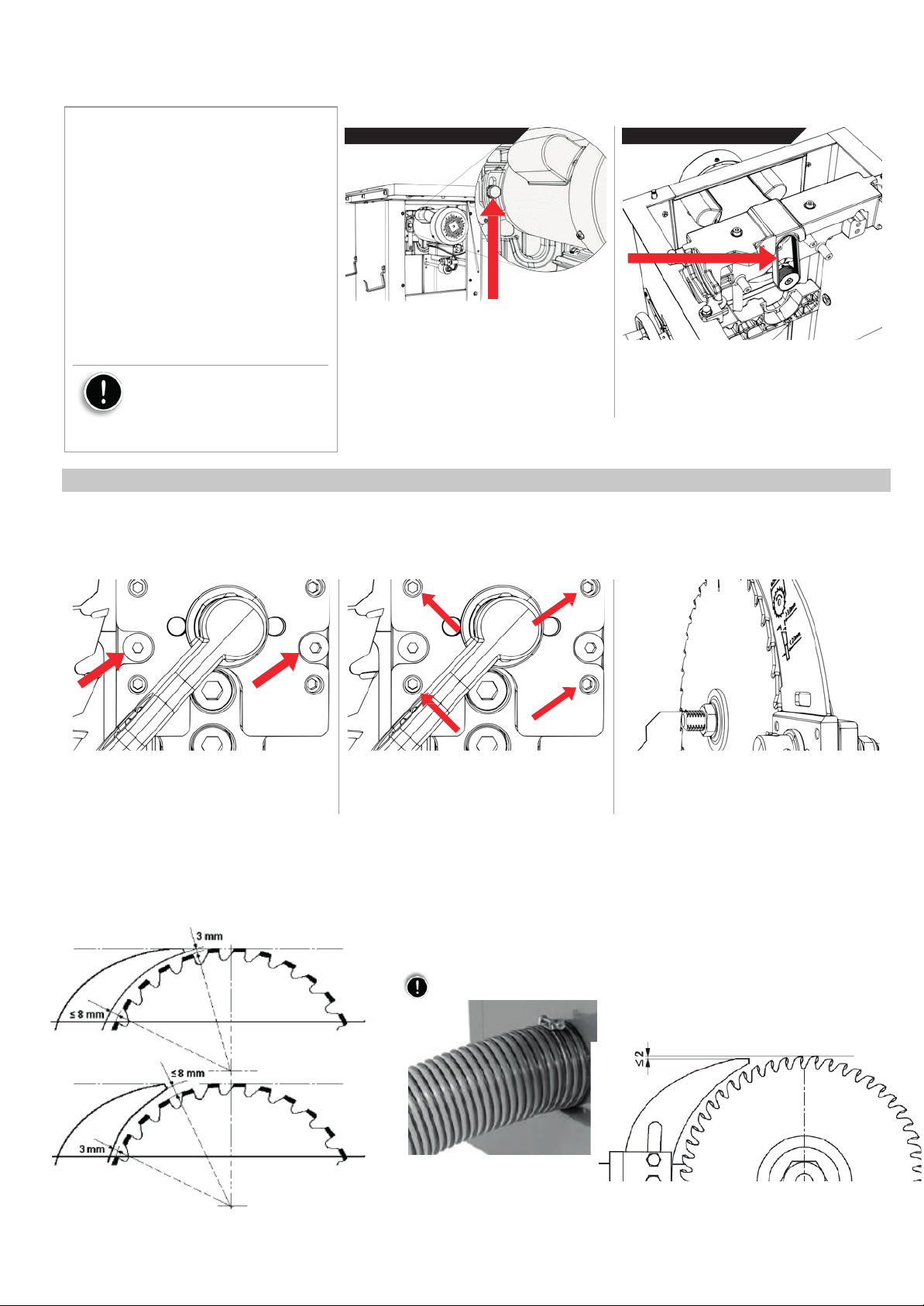
Insert Block Adjustments (For
The Riving knife, blade guard, or splitter must be aligned with the blade to be used affectively. The riving knife should only be used with blades
specified on the riving knife. To adjust the position of the blade safety attachments, relative to the saw blade: NOTE: if the cam action lever does
not lock or is too hard to lock – adjust the ½” nut on the back side of the cam action axil. You will need to remove the motor cover
all
Safety
Accessories):
Loosen the two middle setting bolts. These
two bolts fasten the assembly in-between the
set screws and the arbor block.
Riving Knife
Adjustments:
After changing a saw blade, always check that
the riving knife is correctly set!
Adjust the set screws as needed to correct an out
of align blade attachment. Do small adjustments
and check.
The distance of the riving knife from the
gear rim must be between 3 mm and 8 mm.
The highest point of the riving knife must
be set at least 2mm beneath the topmost
tooth.
The riving knife must be at least 0.2
mm thicker than the main saw blade.
As Adjustments are made, the blade attachments
will translate, not rotate, by design. This ensures
that the workpiece will not get held up. CHECK
COMPONENTS BEFORE EVERY CUT.
Check that the saw blade clamping
system is tight before operating the machine!
Dust Collector
:
19
Page 20
Fusion Tablesaw
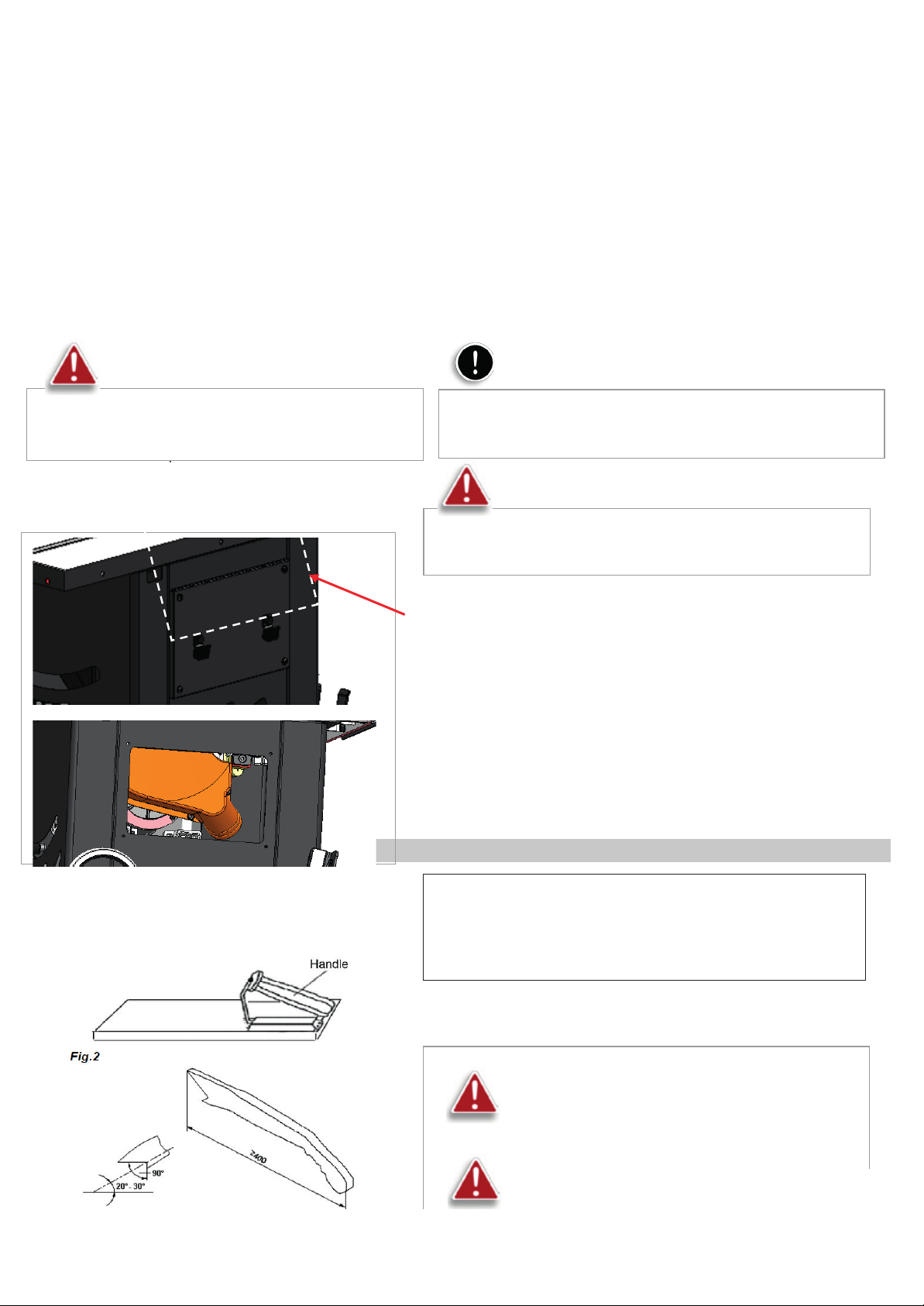
There is a 101.6 mm dust outlet located on the lower left of the saw cabinet allowing for the
connection to a dust collection system (not included).
Air current speed is 20m/s for vacuum suction dust emission index. When air current speed of dust collector device (in accordance with EN
12779:2004+ A1:2009) is not lower than 20m/s, ensure machine can be normal exhausted. User must wear dustproof mask.
1. Fit the 4" dust hose over the dust port, (not included) and secure in place with a hose clamp.
2. Make sure the hose could not come off.
3. Required air flow: 934 m
4. Ensure pressure drop of each dust collector outlet carrying air current speed: 1500Pa
3
/h
5. Wind speed of dust collector tube m/s: dry chips: 20m/s, water content is equal to18% wet chips: 28m/s.
Warning: Always turn on the dust collector
before starting the saw and stop the saw before
To clean wood chips
turning off the dust collector.
PUSH Block and Push stick
Note:
A tight fit is necessary for proper performance.
Warning: Always turn off the table saw before removing
Remove the side cover, to clean and remove dust, debris from dust Hood
any cover of the machine
A push stick (Fig.3) must be used
If the workpiece is less then 120mm, you must use the push stick to
prevent your hands from getting too close to the saw blade.
push block must be used to cut narrow workpieces
to push the workpiece against the fence, a push block can be easily made
by the operator.
Warning: Use only the push stick provided by the
manufacturer or constructed in accordance with the
instructions. This push stick provides sufficient distance of
the hand from the saw blade.
Warning:
damaged push stick may break causing your hand to slip
into the saw blade.
20
Never use a damaged or cut push stick. A
and, when necessary,
Page 21
Fusion Tablesaw
27
Type of Cut
Note: This saw is only designed to cut
Warning:
Always wear safety
glasses,
WARNING: Keep the blade guard installed and in
WARNING: Never reach in towards the blade while the
a respirator and hearing protection when
operating this machine
wood.
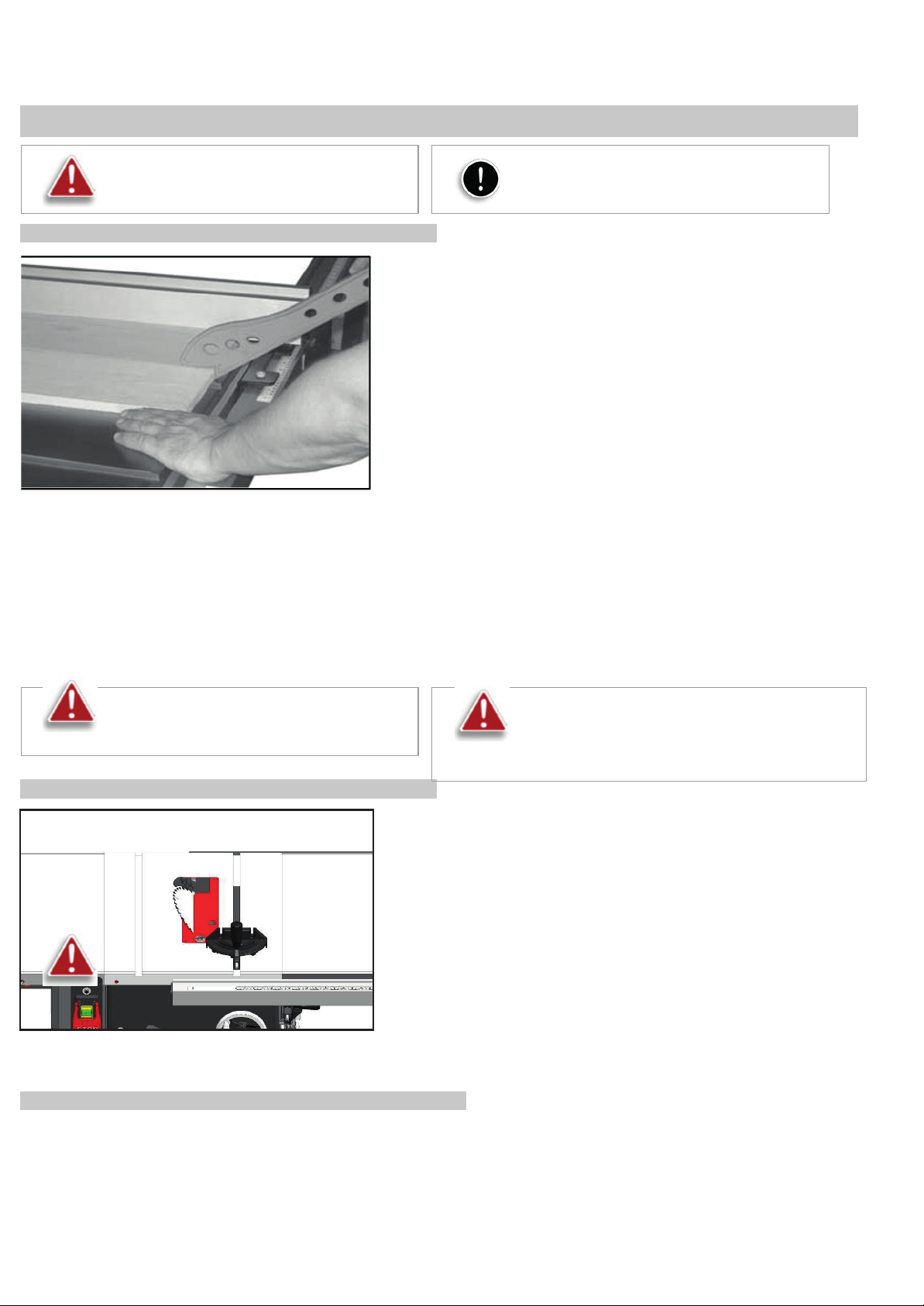
RIPPING
Cutting a wood plank or sheet of plywood lengthwise to reduce its width is
called “ripping”. To rip stock, hold the work with both hands pushing it into the
blade as well as firmly against the rip fence so that it is cut straight.
• Never rip or cut wood without using the fence or mitre gauge to guide it because the
stock could kickback.
• Always use the blade guard and riving knife assembly when cutting wood. The riving
knife prevents the saw “kerf” (the slit cut by the blade) from closing and binding the
blade, which can overload and/or stall the motor or cause the blade to lift and eject
the workpiece towards the front of the saw at very high speeds. The blade guard
keeps your fingers away from the blade and also reduces the amount of sawdust
flying free.
• Raise the saw blade only about 1/4" higher than the workpiece to be cut.
As you complete the rip, the wood will either remain on the table, tilt up to be caught on the end of the guard, or fall onto the floor (or outfeed table).
The waste part of the stock remains on the table to be removed only after the saw is stopped (unless it is large enough for immediate safe removal).
If the work to be ripped is narrow, it is safer to use a push stick, rather than the hands, to feed it into the blade Push sticks with non-slip grippers can be
purchased, but a shop-made one works just as well. When ripping extremely narrow stock that may not clear the width of the blade guard, or very thin
material such as paneling, which may slip between the underside of the fence and the table surface, a strip of wood as an auxi- liary guide can be
attached to the fence
the down position. Failure to do this could result in
serious personal injury or death.
blade is still spinning! whenever a rip cut is completed,
turn off the saw and wait for the blade to come to a
complete stop before reaching in to remove the
BEVEL RIPPING
Bevel ripping is performed the same as ripping but with the saw blade set to an angle
not perpendicular with the table surface. To tilt the blade to the left, anywhere
between 0° and 45°. This is used most often when cutting bevels, compound miters
or chamfers.
After changing the bevel angle verify the alignment of the guard and splitter; make
sure there is clearance with the saw blade.
RIPPING SMALL WORKPIECES
Do not attempt rip cuts if the work piece is too small, as this will oblige you to place your hands too close to the blade and put you at serious risk of
injury. When ripping narrower widths; use a push block or a push stick in order to avoid placing hands near the blade.
21
Page 22
Fusion Tablesaw
Warning: When cross-cutting round
saw blade
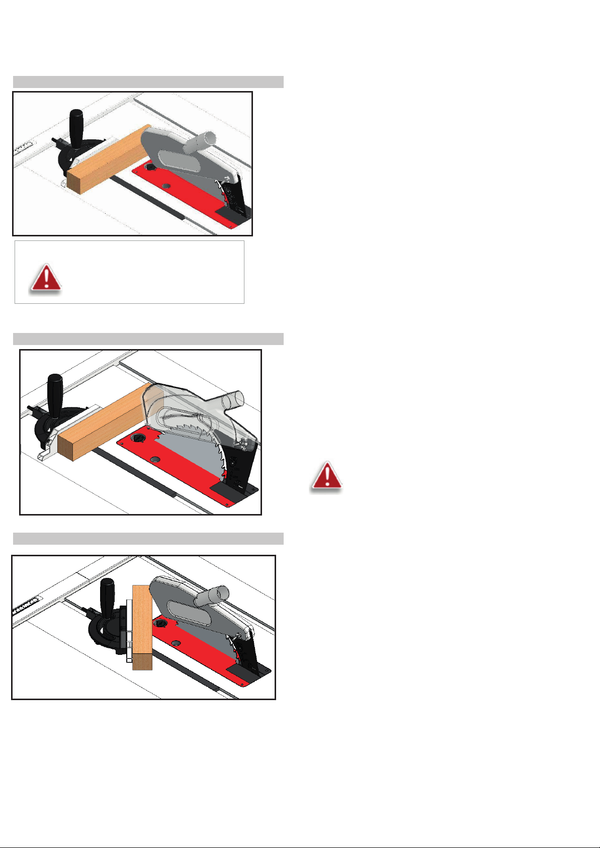
CROSS CUTTING
cut through, move one or both cut pieces.
stock it is necessary to secure the
workpiece against rotation by using a
suitable jig or holder and to use a suitable
BEVEL CROSS CUTTING
MITRE CUTS
Cutting against the grain, to shorten the length of a board is crosscutting. With
some smaller sized and rectangular pieces, you often have the choice of ripping or
crosscutting. Always use the miter gauge, when crosscutting; never cut a piece
unsupported. The miter gauge may be used in either slot, but most operators
prefer the left groove for typical work. When the blade is tilted for bevel cutting, use
the table slot that does not cause interference with your hand or the saw blade
guard.
To begin crosscutting, place the work on the miter gauge and, with the motor OFF,
slide it up close to the blade to align the outer edges of the teeth with your cut mark
Fig.
Keep a firm grip as you pull the miter gauge and the wood back away from the
blade. Lower the blade guard, turn on the saw and make the cut. When the work is
If long enough to handle without danger immediately off to the side, away from the
turning blade. Turn off the motor
This procedure is the same as cross cutting except that the blade is set to an
angle other than 0. After changing the bevel angle, verify the alignment of the
guard and splitter and verify that there is clearance with the saw blade
This operation is the same as cross cutting, except the miter gauge is set to
an angle other than 0. Hold the work piece firmly against the miter gauge
and feed the workpiece slowly into the blade to prevent it from moving during
the cut.
28
22
Page 23
Fusion Tablesaw
k
Maintenance
To keep you Laguna Tools machine in top performance for many years please follow this maintenance schedule and refer to any instructions.
Daily
Check:
• Loose mounting bolts
• Damaged saw blade
• Damaged riving knifes, splitters, or blade guards
• Worn or damaged wires
• Any other unsafe condition
Weekly
Maintenance:
• Clean table surface and miter slot grooves
• Clean and protect cast-iron table
• Clean rip fence
Monthly
• Clean/vacuum dust buildup from inside cabinet and off motors.
• Check/replace belt for proper tension, damage or wear.
Every 6–12
Lubricate trunnion slides.
•
• Lubricate worm gear.
• Lubricate leadscrew
• Lubricate gearing and gearboxes.
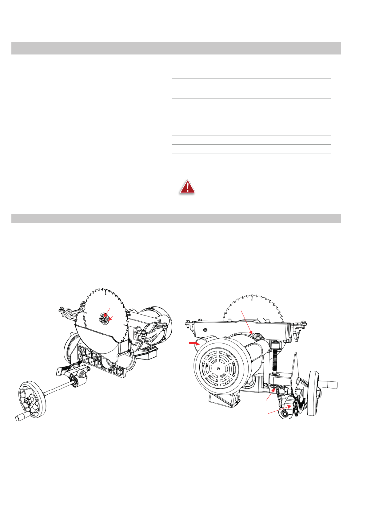
Internal Components Map
Maintenance:
Months:
A. Motor
B. Dust Shroud
C. Trunnion Slides (Support)
D. Upper Trunnion
E. Lower Trunnion
Notes
.
F. Arbor Nut
G. Arbor Washer (Flange)
H. Blade
I. Tilt Gearing
J. Height Gearing
warning: DO NOT perform any of the following steps,
installations, or adjustments with the saw connected to the
power source.
K. Belt (behind blade)
L. Worm Screw
M. Tilt Plate
N. Start Capacitor (see spec sheet)
O. Run Capacitor (see spec sheet)
f
g c
h
c
d
b
n
o
M
A
l
e
j
i
29
23
Page 24

Fusion Tablesaw
Behavior
Possible
Causes
Possible
Solution
1. Start capacitor at fault
1. Test/replace if faulty.
1. Motor or component loose
1. Inspect/replace damaged bolts/nuts, and re-tighten
1. Feed rate/cutting speed too fast
1. Decrease feed rate/cutting speed.
Trouble-Shooting
Machine will not start or
continues to trip the breaker.
Machine is excessively loud
is experiencing
vibration.
excessive
2. Motor connection wired wrong
3. Wiring at fault
4. Motor Start/Stop switch at fault
5. Motor at fault
6. Run capacitor at fault
7. Wall circuit breaker tripped or at fault
8. Power supply switched OFF or at fault
9. Plug/receptacle at fault or wired incorrectly
2. Blade at fault
3. Motor mount loose/broken
4. Machine incorrectly mounted
or
5. Arbor pulley loose
6. Belts worn or loose
7. Pulley loose or at fault
8. Arbor bearings at fault
9. Motor bearings at fault
2. Correct motor wiring connections.
3. Check/fix broken, disconnected, or corroded wires.
4. Replace switch.
5. Test/repair/replace.
6. Test/replace if faulty.
7. Ensure circuit size is correct/replace weak breaker.
8. Ensure power supply is on/has correct voltage.
9. Test wires and contacts; correct the wiring.
with thread-locking fluid.
2. Replace warped/bent blade; re-sharpen dull blade.
3. Tighten/replace.
4. Tighten mounting bolts; relocate/shim machine.
5. Retighten/replace arbor pulley.
6. Adjust tension of/replace belt
7. Realign/replace shaft, pulley, setscrew, and key.
8. Replace arbor housing bearings; replace arbor.
9. Test by rotating shaft; grinding/loose shaft requires
bearing replacement.
Machine trips the
or feels
underpowered
during
operation.
overload,
2. Workpiece material unsuitable for machine
3. Pulley/sprocket slipping on shaft
4. Motor bearings at fault
5. Contactor at fault
6. Motor overheated
7. Workpiece crooked; fence not aligned
8. Machine undersized for task; wrong blade
9. Run capacitor at fault
10. Belt is slipping from pulley
11. Motor wired incorrectly
12. Plug/receptacle at fault
13. Motor at fault
2. Only cut wood; ensure moisture is below 20%.
3. Replace loose pulley/shaft.
4. Test/repair/replace.
5. Test for good contacts/correct wiring.
6. Clean motor, let cool, and reduce workload.
7. Straighten or replace workpiece; adjust fence.
8. Use correct blade; reduce feed rate or depth of cut.
9. Test all legs for power/replace if faulty.
10. Adjust tension of/replace belt.
11. Test/repair/replace.
12. Wire motor correctly.
13. Test/repair/replace.
30
24
Page 25
Fusion Tablesaw
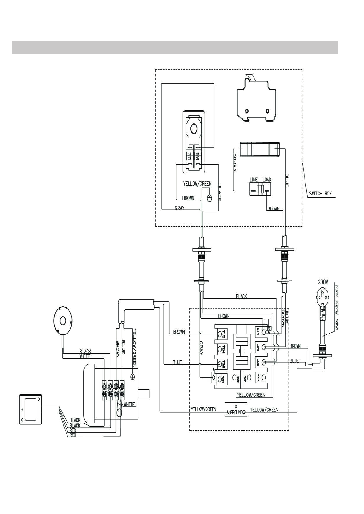
Wiring Diagram: Fusion F3 230V
32
25
Page 26
Fusion Tablesaw
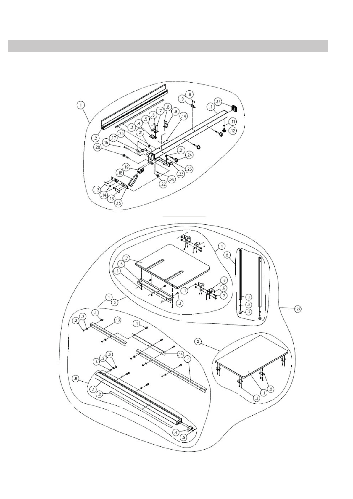
Parts Diagrams
Fence
Assembly
33
26
Page 27
Fusion Tablesaw
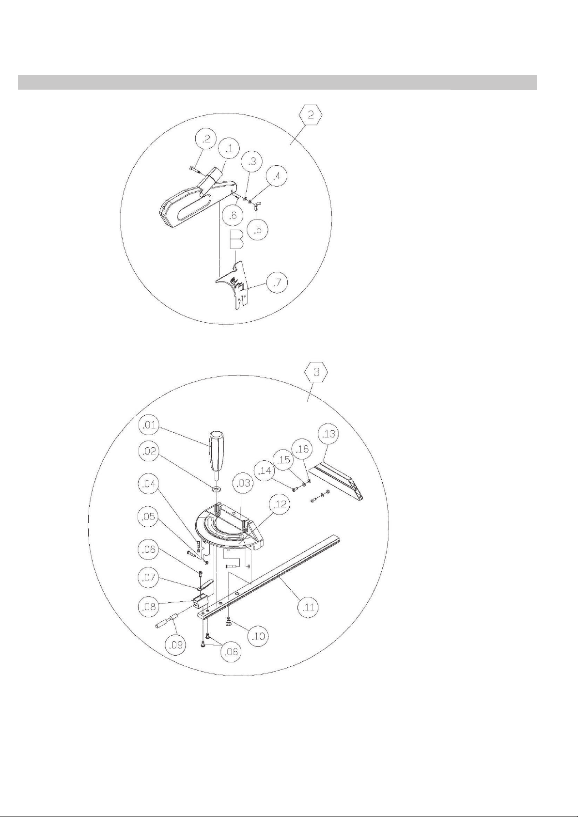
MITRE GAUGE, Blade guard
34
27
Page 28
Fusion Tablesaw
Motor and Trunnion
35
28
Page 29
Fusion Tablesaw
36
cabinet
29
Page 30
Fusion Tablesaw
37
F3 Cabinet
30
Page 31

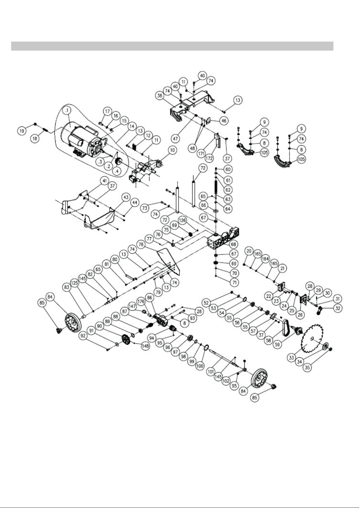
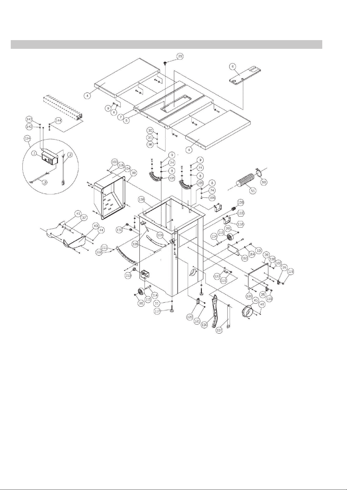
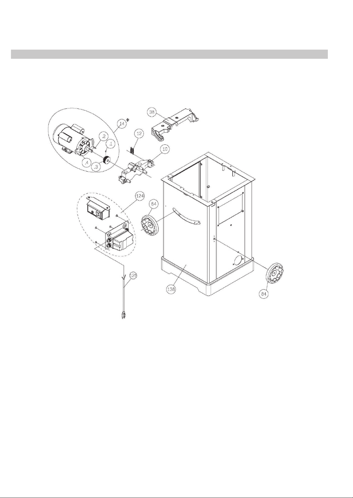
Key Part No. Descriptions Specification Q'ty
1 924707-001 Fence Assembly 1
.1 174712-308 Fence Body 1
.2 310511-909 Adaptor 1
.3 174713-000 Fix Plate 1
.4 250799-620 Pointer 1
.5 172847-905 Pointer Bracket 1
.6 001101-205 Round Head Screw M3*1.06P*6 2
.7 000304-210 Pan Head Screw M6*1.0P*6 2
.8 000302-101 Pan Head Screw M4*0.7P*6 4
.9 270007-901 Plate 2
.11 008005-100 Hex. Nut M6*1.0P(10B*5H) 1
.12 250587-615 Frictional Wheel 1
.13 250471-621 Frictional Plate 2
.14 002103-103 Flat Head Screw M6*1.0P*8 2
.15 172341-904 Bracket for Frictional Plate 1
.16 000002-308 Hex. Screw M6*1.0P*45 1
.17 171993-904 Bracket 1
.18 230301-615 Handle 1
.19 922141-001 Compress Cam Assembly 1
.20 000004-306 Hex. Screw M10*1.5P*50 1
.21 250472-621 Plastic Set Screw M12*1.75P 2
.22 008308-100 Lock Nut M10*1.5P(17B*12H) 1
.23 001902-109 SET Lock Screw M6*1.0P*6 2
.24 251354-615 Wing Screw 3
.25 250602-621 Frictional Plate 1
.26 008304-100 Lock Nut M6*1.0P(10B*6H) 1
.33 574997-000 Wear-resistant Sticker 2
.34 250557-615 End Cap 1
2 924708-001 Blade Guard Assembly 1
.1 924709-001 Blade Guard Cover 1
.2 001003-201 Shoulder Screw M6*1.0P*40 1
.3 006002-023 Flat Washer 6.3*13*2.0t 1
.4 006303-100 Spring Washer 6.5*10.5 1
.5 008404-200 Wing Nut M6*1.0P 1
.6 001201-601 Tapping Screw M4*1.41P*12L 1
.7 174714-904 Riving Knife 1
3 924710-001 Miter Gauge Assembly 1
.1 230140-615 Handle 1
.2 006002-051 Flat Washer 8.5*18*3.0t 1
31
Page 32

Key Part No. Descriptions Specification Q'ty
.3 090109-008 Miter Gauge Body 1
.4 000302-108 Pan Head Screw M4*0.7P*20 3
.5 008002-100 Hex. Nut M4*0.7P(7B*3.2H) 3
.6 003303-105 Pan Head Screw 3/16"-24NC*3/8" 3
.7 250226-620 Pointer 1
.8 130053-903 Spacer 1
.9 360381-901 Fixing Rod 1
.10 290023-902 Shoulder Screw 1
.11 310496-904 Slot Bar 1
.12 571614-000 Scale 1
.13 043716-000 O-Ring AS008 1
.14 310536-909 Fence Plate 1
.15 000304-209 Pan Head Screw M6*1.0P*20 2
.16 006002-023 Flat Washer 6.3*13*2.0t 2
.18 174721-000 Fix Plate 1
4 051437-008 Extension Table 2
5 011001-103 Spring Pin 3*10 1
6 924793-001 Table Insert Assembly 1
.1 251355-663 Table Insert 1
.2 001901-104 SET Lock Screw M5*0.8P*12 4
.3 002002-101 Pan Head Screw M5*0.8P*8 2
.4 006011-187 Flat Washer 5.3*16*1t 2
7 051426-008 Table 1
8 006001-049 Flat Washer 8.5*16*2.0t 18
9 000003-105 Hex. Screw M8*1.25P*25 10
*10 090322-000 Up-down Bracket for Fusion2 1
*10 051370-000 Up-down Bracket for Fusion2 1
11 008006-100 Hex. Nut M8*1.25P(13B*6.5H) 6
*12 280258-905 Spring for Fusion2 1
*12 280258-905 Spring for Fusion3 1
13 000104-106 Cap Screw M8*1.25P*20 5
*14 901203-001 Motor Assembly for Fusion2 2100W*230V*50HZ*1PH 1
*14 901216-001 Motor Assembly for Fusion3 2100W*230V*50HZ*1PH 1
15 006001-069 Flat Washer 10*20*3.0t 1
16 006307-100 Spring Washer 10.2*18.5 1
17 000004-103 Hex. Screw M10*1.5P*30 1
18 360863-901 Motor Fixing Shaft 1
19 008308-100 Lock Nut M10*1.5P(17B*12H) 1
20 008306-100 Lock Nut M8*1.25P(13B*9H) 3
32
Page 33

Key Part No. Descriptions Specification Q'ty
21 010005-000 Retaining Ring STW-14 1
22 130359-903 Bracket for Riving Knife 1
23 000104-104 Cap Screw M8*1.25P*16 2
24 280259-901 Spring 1
25 130363-903 Bushing 1
26 110073-000 Block 1
28 001902-710 SET Lock Screw M6*1.0P*8 5
29 000804-106 Round Head Screw M5*0.8P*16 2
30 361251-905 Pin 1
31 361250-901 Fixing Knob 1
32 110071-000 Lock Handle 1
33 390040-000 Saw Blade 250mm x 30mm x 40T 1
34 130388-000 Sawblade Clamp 1
35 380205-901 Nut TW5/8"-12 1
36 008302-100 Lock Nut M5*0.8P(8B*6H) 1
37 002503-101 Round Head Socket Lock Screw M5*0.8P*12 8
*38 090323-000 Upper Trunnion for Fusion2 1
*38 051369-000 Upper Trunnion for Fusion3 1
39 008304-100 Lock Nut M6*1.0P(10B*6H) 8
40 002601-107 Locking CAP screw M8*1.25P*25 2
41 174773-000 Fixing Plate 1
43 251398-615 Dust Hood 1
44 002002-101 Round Head Phillip Screw M5*0.8P*8 5
45 251418-615 Adaptor 1
46 174716-019 Arbor Lock Handle 1
47 280260-901 Spring 1
48 010206-000 Retaining Ring ETW-9 2
49 000303-104 Pan Head Screw M5*0.8P*12 3
50 042608-000 Clamp I.D.60-80mm 2
51 042620-008 Dust Hose 2.5”(I.D.)*800mm 1
52 008316-200 Lock Nut M10*1.5P(17B*8H) 1
53 006001-075 Flat Washer 10.3*22*2.0t 1
54 010103-000 Retaining Ring RTW-35 1
55 030211-002 Ball Bearing 6003 2
56 190270-901 Spacer 1
57 174305-901 Fixed Plate 1
58 014360-000 Poly-V-Belt 139J-7 1
59 361351-902 Arbor 1
60 000002-103 Hex. Screw M6*1.0P*16 1
33
Page 34

Key Part No. Descriptions Specification Q'ty
61 006001-020 Flat Washer 6.2*20*3.0t 1
62 006007-114 Flat Washer 6.4*16*1.6t 1
63 361245-901 Lead Screw 1
64 010007-000 Retaining Ring STW-16 1
65 012002-003 Key 4*4*8 2
66 174324-000 Washer 1
67 031011-001 Bearing 51100 2
68 090324-000 Trunnion Base 1
69 130257-000 Bevel Gear 2
70 006001-025 Flat Washer 6.4*16*1.0t 1
71 008317-300 Lock Nut M6*1.0P(10B*5H) 1
72 361246-000 Column 2
73 002601-108 Locking CAP screw M8*1.25P*35 2
74 006305-100 Spring Washer 8.2*15.4 13
75 006001-078 Flat Washer 10.5*19*1.5t 1
76 190273-901 Spacer 1
77 000202-101 SET Screw M5*0.8P*5 2
78 174309-901 Rotary Gear Plate 1
79 011004-101 Spring Pin 6*16 2
80 174322-156 Pointer 1
81 002402-101 Round Head Lock Screw w/Washer M5*0.8P*12/5*10.5*1.0t 1
82 361261-901 Shaft 1
83 251276-615 Bushing 1
*84 240061-008 Handwheel Assembly forFusion2 2
*84 924505-001 Handwheel Assembly for Fusion3 2
85 920703-001 Fixing Knob 2
86 090326-000 Worm Gear Box 1
87 320411-901 Worm Gear Shaft 1
88 030106-001 Ball Bearing 6201 1
89 010102-000 Retaining Ring RTW-32 1
90 130361-000 Gear 1
91 006001-127 Flat Washer 5.5*22*2.0t 1
92 000001-109 Hex. Screw M5*0.8P*12 1
93 000104-113 Cap Screw M8*1.25P*45 2
94 320411-901 Worm Shaft 1
95 001902-109 SET Lock Screw M6*1.0P*6 3
96 012002-007 Key 4*4*20 1
97 030104-001 Ball Bearing 6005 1
98 010011-000 Retaining Ring STW-25 1
34
Page 35

Key Part No. Descriptions Specification Q'ty
99 010004-000 Retaining Ring STW-13 1
100 010107-000 Retaining Ring RTW-47 1
101 361262-901 Shaft 1
102 360734-901 Bushing 1
103 000304-113 Pan Head Screw M6*1.0P*30 8
104 174789-196 Motor Cover 1
105 051135-000 Trunnion Support 2
106 000003-104 Hex. Screw M8*1.25P*20 4
107 174315-904 Arbor Wrench 1
108 008005-100 Hex. Nut M6*1.0P(10B*5H) 2
109 000002-105 Hex. Screw M6*1.0P*25 2
110 020008-000 Strain Relief SBR5-2 2
111 006001-001 Flat Washer 4.3*10*1.0t 2
112 000302-102 Pan Head Screw M4*0.7P*8 2
113 004001-101 Knob 5/16"-18NC*3/4" 2
114 000003-316 Hex. Screw M8*1.25P*60 2
115 250399-615 Wheel 2
117 230041-000 Leveling Foot 2
118 170541-904 Slide Shelf 2
119 049201-101 Hex. Screw w/Flat Washer M8*1.25P*16/(13B*6.5H) 2
120 174717-196 Side Cover 1
121 001603-102 Round Head Screw w/Washer M6*1.0P*10/6*13.2*1.0t 2
122 170965-904 Fix Plate 1
123 250407-615 Worm Shaft Bracket 1
*124 937985-001
*124 938029-001
Magnetic Switch Assembly for Fusion2
Magnetic Switch Assembly for Fusion3
1 938000-001 Magnetic Switch Assembly KJD-17-230V-BW 1
.1 251360-615 Switch Box 1
.2 924817-001 Reset Switch 16AMP(220V-240V) 1
.3 471044-024 Connect Cord 14AWG*1C*100mm 1
.4 174718-000 Fixed Plate 1
.5 001201-405 Tapping Screw M4*1.41P*16 2
.6 174719-904 Switch Plate 1
.7 023705-011 Strain Relief PGA13.5-08B 2
.8 491199-000 Fuse Assembly RT18-32X, 32A, AC690V/DC440V 1
.10 006002-139 Flat Washer 3*8*1.0t 2
.11 000301-205 Pan Head Screw M3*0.5P*25 2
.12 820013-001 Magnetic Switch Assembly 220V-240VKJD-17-230 1
.13 000302-101 Pan Head Screw M4*0.7P*6 2
1
1
35
Page 36

Key Part No. Descriptions Specification Q'ty
.14 006501-100 Tooth Washer 4.3*8.5(BW-4) 2
.15 023705-011 O-Ring P5 1
.16 340136-615 Seal Ring 1
.17 010201-000 Retaining Ring ETW-3 4
.18 001201-709 Tapping Screw M4*1.41P*25 4
2 938043-001 Magnetic Switch Assembly 3HP*220V-240V*1PH 1
3 491193-000 CE Plug P331-(IP44) 1
4 174971-904 Cord Fixing Plate (M6) 1
5 023705-011 Strain Relief PGB13.5-12B 1
125 043322-000 O-Ring P11 1
126 010001-000 Retaining Ring STW-10 1
127 925001-001 36" Rail & Rear Table Assembly 1
1 925002-001 36" Rail 1
1.1 001803-103 CAP Screw w/ Spring Washer M8*1.25P*25/8.2*13.7 7
1.2 006001-049 Flat Washer 8.5*16*2.0t 12
1.3 008006-100 Hex. Nut M8*1.25P(13B*6.5H) 12
1.4 048701-101 Square Screw M8*1.25P*20 5
1.7 174352-308 Rear Rail 8.2*15.4 1
1.8 924795-001 Front Rail Assembly 1
1.8.1 310546-911 Front Rail 1
1.8.2 573036-000 Scale 36" 1
1.8.4 250699-615 End Cap - R 1
1.8.5 001102-604 Round Hear Tapping Screw 0”~36” 2
1.13 174477-308 Rear Rail - L 1
1.14 174720-904 Connect Plate M4*1.59P*12 1
2 925003-001 Infill Table Assembly 1
2.1 440110-000 Infill Table 1
2.2 173139-902 Brace 4
2.3 230086-901 Tapping Screw 8
3 924796-001 Rear Table . Leg Assembly 1
3.1 924797-001 Rear Table . Leg Assembly 1
3.1.1 008308-100 Lock Nut M10*1.5P(17B*12H) 4
3.1.2 000004-112 Hex. Screw M10*1.5P*45 4
3.1.3 049201-101 Hex. Screw w/Flat Washer M8*1.25P*16/(13B*6.5H) 3
3.1.5 174780-904 Support Plate 1
3.1.6 001102-505 Round Hear Tapping Screw M4*1.59P*16 16
3.1.7 440099-000 Rear Table 1
3.1.8 171301-904 Fixed Plate 4
3.2 924798-001 Leg Assembly 1
36
Page 37

Key Part No. Descriptions Specification Q'ty
3.2.1 190208-365 Leg 2
3.2.2 008006-100 Hex. Nut M8*1.25P(13B*6.5H) 2
3.2.3 230041-000 Leveling Foot S20C+NBR 2
130 251362-615 Push Sticks 1
133 040002-000 Hex. Wrench 2.5mm 1
134 040006-000 Hex. Wrench 6mm 1
135 174569-904 Open Wrench 10*13 1
*138 174779-196 Cabinet for Fusion2 1
*138 174779-196 Cabinet for Fusion3 1
142 000002-101 Hex. Screw M6*1.0P*12 2
143 006001-033 Flat Washer 6.7*16*1.0t 2
144 008603-100 Square Screw M6*1.0P(10B*5H) 2
145 012002-005 Key 4*4*12 2
147 130368-903 Adjusting Bushing 1
148 001901-101 SET Lock Screw M5*0.8P*5 1
157 006001-137 Flat Washer 5.3*16*1.5t 1
159 170542-904 Hook 2
160 002504-102 Round Head Socket Lock Screw M4*0.7P*6 4
161 002402-102 Round Head Lock Screw w/Washer M5*0.8P*10-5*16*1.5t 4
162 006701-100 Wave Washer WW-6 1
164 006001-045 Flat Washer 8.5*16*1.0t 1
165 006702-100 Wave Washer WW-8 2
166 174711-000 Fix Plate 2
167 000003-102 Hex. Screw M8*1.25P*16 4
168 251358-615 Knob 1
169 049201-102 Hex. Screw w/Flat Washer M8*1.25P*12/(13B*5.5H) 3
*170 924854-001 Over Head Guards Assembly 36"
.1 042620-015 Dust Hose 1.5”(I.D.)*2700mm 1
.2 174887-904 Bracket 1
.4 850913-000 Hardware Bag for Overhead Guard 1
.4.1 042622-001 Clamp 1.5" 2
.4.2 001803-103 CAP Screw w/ Spring Washer M8*1.25P*25/8.2*13.7 1
.4.3 006001-049 Flat Washer 8.5*16*2.0t 1
.4.4 008006-100 Hex. Nut M8*1.25P(13B*6.5H) 1
171 200108-000 Sponge 1
172 174772-000 Plate 1
173 924807-001 Front Rail (L) Assembly 1
.1 310545-911 Front Rail (L) 1
.2 250698-615 End Cap 1
37
Page 38

Key Part No. Descriptions Specification Q'ty
.3 001102-604 Round Hear Tapping Screw M4*1.59P*12 2
.4 006001-049 Flat Washer 8.5*16*2.0t 2
.5 008006-100 Hex. Nut M8*1.25P(13B*6.5H) 2
.6 048701-101 Square Screw M8*1.25P*20 2
.7 360249-905 Connect Pin 2
175 000304-102 Round Head Phillip Screw M6*1.0P*10 2
176 190324-901 Spacer 1
Warranty
New machines and accessories sold by Laguna Tools carry a one-year warranty effective from the date of shipping.
Laguna Tools guarantees all new machines and accessories sold to be free of manufacturers’ defective workmanship, parts and materials. We will repair or replace, without charge, any parts determined by Laguna Tools, Inc. to be a manufacturer’s defect.
We require that the defective item/part be returned to the Laguna appointed dealer you purchased from with the complaint. Photographic / videos maybe required
when any fault is reported so we can agree action needed. Any machines returned
to Laguna appointed dealer must be returned with packaging in the same manner
in which it was received. If a part or blade is being returned it must have adequate
packaging to ensure no damage is received during shipping. In the event the item/
part is determined to be damaged due to lack of maintenance, cleaning or misuse/
abuse, the customer will be responsible for the cost to replace the item/part, plus all
related shipping charges. This limited warranty does not apply to natural disasters,
acts of terrorism, normal wear and tear, product failure due to lack of maintenance or
cleaning, damage caused by accident, neglect, lack of or inadequate dust collection,
misuse/abuse or damage caused where repair or alterations have been made or attempted by others. Laguna Tools, Inc. is not responsible for additional tools or modifications sold or performed (other than from/by Laguna Tools, Inc.) on any Laguna
Tools, Inc. machine.
Warranty maybe voided upon the addition of such described tools and/or modifications, determined on a case-by-case basis.
Normal user alignment, adjustment, tuning, machine settings and consumables ie;
blades are not covered by this warranty. It is the responsibility of the user to understand basic machinery operation, settings and procedures and to properly maintain
the equipment in accordance with the standards provided by the manufacturer.
The labour required to install replacement parts is the responsibility of the user.
Laguna Tools is not responsible for damage or loss caused by a freight company or
other circumstances not in our control.
All claims for loss or damaged goods must be notified to the authorised dealer within
twenty-four hours, if the machine is received damaged it must be signed for damaged.
Only new machines sold to the original owner are covered by this warranty.
38
Page 39

Declaration of Conformity
Product model: F3 Fusion Table Saw
Name and address of the manufacturer: Laguna Tools Inc. 2072 Alton Parkway, Irvine, California
92606, USA.
Name and address of the UK Authorised Representative: Axminster Tool Centre Ltd, Unit 10 Weycroft
Avenue, Axminster, Devon EX13 5PH, United Kingdom.
This declaration of conformity is issued under the sole responsibility of the manufacturer.
Object of the declaration: F3 Fusion Table Saw
The object of the declaration described above is in conformity with the relevant GB legislation:
Supply of Machinery (Safety) Regulations 2008 as amended.
Electromagnetic Compatibility Regulations 2016 as amended.
Laguna Tools Inc.
UK DECLARATION OF CONFORMITY
‘original’
References to the relevant harmonised standards used or references to the other technical
specifications in relation to which conformity is declared:
EN ISO 12100:2010 Safety of Machinery. General principles for design. Risk assessment and
risk reduction.
ISO 19085-9:2020 Woodworking machines - Safety - Part 9: Circular saw benches (with and
without sliding table) (ISO 19085-9:2019)
EN 60204-1:2018 Safety of machinery - Electrical equipment of machines - Part 1: General
requirements (IEC 60204-1:2016, modified)
Additional information:
Name and address of person authorised to compile the technical file: Axminster Tool Centre
Ltd, Unit 10 Weycroft Avenue, Axminster, Devon EX13 5PH, United Kingdom
The machinery fulfils all relevant provisions of Supply of Machinery (Safety) Regulations 2008
as amended.
Signed for and behalf of: Axminster Tool Centre Ltd.
(place and date of issue): Axminster, Devon, United Kingdom, 20th June 2024
(name, function): Andrew Parkhouse, Supply Chain Director
Signature:
39
Page 40

Distributed by
The packaging is suitable for recycling.
Please dispose of it in a responsible manner.
EU Countries Only
Do not dispose of electric tools together with household waste material.
By law they must be collected and recycled separately.
For after sales help visit
axminstertools.com or call 03332 406406
Axminster Tools, Axminster Devon EX13 5PH
 Loading...