

Page 1
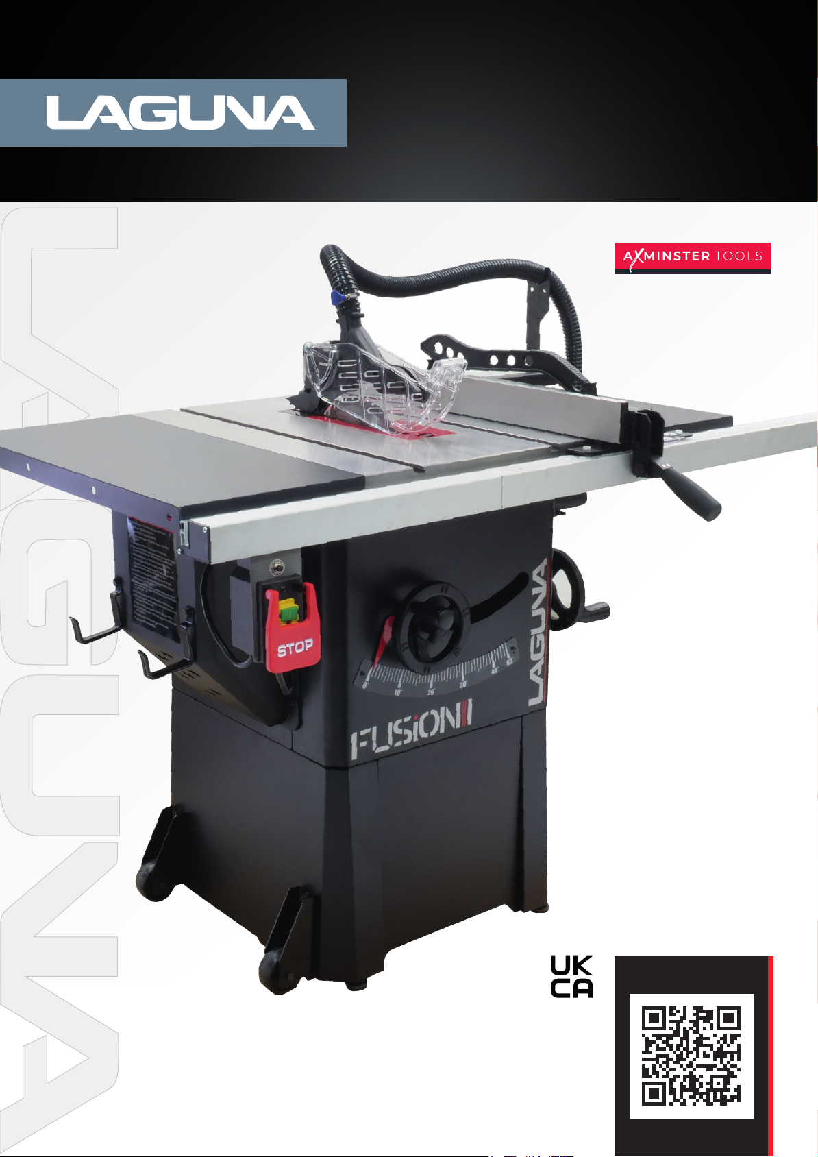
F 1 Fusion
Table Saw 230v
Code: 111785
Distributed by
N.B. Some pictures and diagrams in this manual may have buttons and electrical configurations
which differ slightly from the machine you purchased
Version: 4
Date: 1/10/25
DIGITAL MANUAL
Page 2

Contents
Safety 3
Specifications 4
Setup 7
Setup Help Sections 11
Base & Cabinet 12
Wings, Rails, & Fence 14
Installing/Removing the Blade Guard 15
Installing/Removing the Blade 15
Rear Extension Table 16
Table/Blade/Fence Alignment 18
Safety Device Alignment 18
Installing/Removing Throatplate 19
Installing/Removing Safety Accessories 20
Maintenance and Troubleshooting 21
Troubleshooting 22
Wiring 23
Parts 27
List 28
Conformity Certificates 29
Warranty & Support 30
2
Page 3

SAFETY
The following is a list of safety precautions you must consider when using a Table saw:
ALWAYS REMEMBER TO DISCONNECT THE POWER
TO THE TABLE SAW WHEN MAKING REPAIRS OR
ADJUSTING BLADES AND GUARDS.
• Eye and ear protection are required when operating a
Table saw. Dust extraction & respiratory PPE are highly
recommended.
• Do not wear gloves, loose clothing, jewellery, or any
dangling objects when operating a Table saw.
• Do not allow children to operate the machine.
• At all times all guards must be in place and fully
operational. If a guard seems to be missing or
damaged, adjust, replace or repair immediately.
• A riving knife MUST be used at all times when
performing through cuts and must be positioned
correctly.
• Ensure that the Rip fence is correctly aligned to the
blade to help prevent the risk of timber kick back.
• Never perform “free hand” cuts, a rip fence or mitre
cross cut fence should always be used.
• Never pull the timber through the blade from the rear
of the machine, always push through from the front.
• Disconnect the power to the Table saw when making
repairs or adjusting blades and guards.
• Hands and fingers must be kept clear of the blade,
always use push sticks when feeding smaller pieces into
the blade.
• Use only the recommended blade size and type for the
machine - see page (20) for recommendations.
ALWAYS REMEMBER TO READ THROUGH
THE MACHINE INSTRUCTIONS SUPPLIED.
Kickback
• The most common accidents among table saw users,
according to statistics, can be linked to kickback, the
high-speed ejection of timber from the table saw that
can strike the operator. Kickback can also result in the
operator’s hands making contact with the blade.
Kickback Prevention
• Tips to avoid the most common causes of kickback:
• Make sure the riving knife is always aligned with the
blade. A workpiece can bind or stop the flow of the cut
if the riving knife is misaligned, and result in kickback.
• Use a riving knife during every cut. The riving knife
maintains the kerf in the workpiece, which will reduce
the chance of kickback.
• Never attempt freehand cuts.
• The workpiece must be fed parallel to the blade,
otherwise kickback will likely occur. Always use the rip
fence or mitre gauge to support the workpiece.
• Make sure that the rip fence is parallel to the blade. If
not, the chances of kickback are very high. Take the time
to check and adjust the rip fence.
• Feed cuts through to completion. Anytime you stop
feeding a workpiece that is in the middle of a cut, the
chance of binding, resulting in kickback, is greatly increased.
• Ensure all blades are sharp and in good condition.
• Never cut pieces smaller than the table insert size.
• Long material should be supported at the same height
as the saw table.
• To avoid contact with a coasting blade, do not reach into
the cutting area until the blade comes to a full stop.
• Make sure the blade is not in contact with the material
when you start the saw.
• Never leave the machine unattended when it is running.
•Keep the table top & surrounding work area free from
excessive dust and debris to help prevent slipping or
tripping.
• Maintain a balanced stance at all times so that you do
not fall or lean against the blade or other moving parts.
Do not overreach or use excessive force to perform any
machine operation.
More safety information can be found at: http://www.hse.gov.uk/pubns/wis16.pdf
Tips for Kickback Protection
Kickback can happen even if precautions are taken to
prevent it. Listed below are some tips to protect you if
kickback does occur:
• Stand to the side of the blade when cutting. An ejected
workpiece usually travels directly in front of the blade.
• Wear safety glasses or a face shield. Your eyes and face
are the most vulnerable part of your body.
• Never place your hand behind the blade & never pull the
timber through the cut. If kickback occurs, your hand will
be pulled into the blade.
• Use a push stick to keep your hands further away from
the moving blade. If a kickback occurs, the push stick will
most likely take the damage that your hand would have
received.
3
Page 4
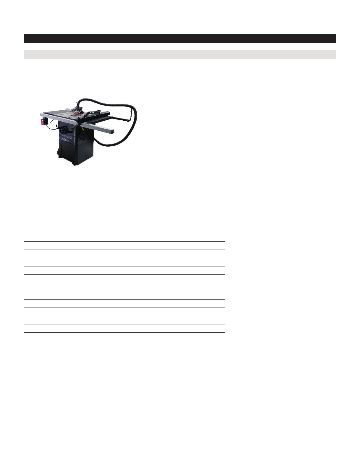
Specifications
Fusion F1 Table Saw (MTSF132110150-0130)
F1 Table Saw
Maximum Blade Diameter/bore 250 mm / 30 mm
Condensed Spec
Max Rip Right of Blade w/Included
Maximum Blade Diameter ....................................................... 10 in. (254 mm)
Fence & Rails 787.4 mm without sub fence
Max Rip Right of Blade w/Included Fence & Rails ................. 31 in. (787.4 mm)
Fence Type Camlock T-Shape w/Aluminium Sub Fence
Fence Type................................................................................ Camlock T-Shape w/Aluminum Face
Table Precision-Ground Cast Iron
Table .......................................................................................... Precision-Ground Cast Iron
Extension tables Pre-Formed Steel
Wings......................................................................................... Pre-Formed Steel
Cabinet Pre-Formed Steel
Cabinet ...................................................................................... Pre-Formed Steel
Trunnions Cast Alloy Dust
Trunnions .................................................................................. Cast Alloy
Port Size 101.6 mm
Blade Guard Dust Port Size 38.1 mm
Dust Port Size ........................................................................... 4 in. (101.6 mm)
Weight, Gross 120 KG
Blade Guard Dust Port Size ..................................................... 1.5 in. (38.1 mm)
Weight, Net 110 KG
Weight, Gross............................................................................ 214 Lbs (97 Kg)
Overall Width (side-to-side) 1550 mm
Weight, Net................................................................................ 195 lbs. (88.5 Kg)
Overall Depth (front-to-back) 1575 mm
Overall Width (side-to-side) ..................................................... 58.81 in. (1494 mm)
Table Height 869 mm
Overall Depth (front-to-back) ................................................... 37.2 in. (945 mm)
Power Requirement 13A, 230V
Overall Height ........................................................................... 42.51 in. (1080 mm)
Motor power 1.5HP, 1450W
Power Requirement .................................................................. 110V, Single-Phase, 60 Hz
Country of Origin Taiwan
Horsepower .............................................................................. 1.5HP
Country of Origin ...................................................................... Taiwan
Certified by a Nationally Recognized Testing Laboratory (NRTL) Yes
F1 Features
Fusion Hi-Lo Dust Collection
Fusion Over-Under Trunnions
Polished Cast Iron Table
Reset Switch
Quick-Release Blade Guard
Riving Knife Included
Push Stick included
Mitre Guage Included
15
4
Page 5

Blade Changing Tool Included
Integrated Tool Storage
Premium Handles
Included 10 x 60T Carbide-Tipped Blade
Premium Arbor and Motor Bearings
Main Information
Table Saw Type ........................................................................ Hybrid Cabinet
Maximum Blade Diameter ....................................................... 10 in. (254 mm)
Arbor Size .................................................................................. 0.62 in. (15.87 mm)
Arbor Speed .............................................................................. 4000 RPM
Blade Tilt Direction ................................................................... Left
Max Blade Tilt ........................................................................... 45 deg.
Maximum Depth of Cut At 90 Degrees ................................... 3.12 in. (79.37 mm)
Maximum Depth of Cut At 45 Degrees ................................... 2.12 in. (53.97 mm)
Max Rip Right of Blade w/Included Fence & Rails ................. 31 in. (787.4 mm)
Max Rip Left of Blade w/Included Fence & Rails ................... 19.68 in. (500 mm)
Additional Blade Information
Included Blade Information ..................................................... 10" x 60T
Riving Knife/Spreader Thickness ............................................ 0.09 in. (2.28 mm)
Required Blade Body Thickness .............................................. >3.0mm
Required Blade Kerf Thickness ............................................... <2.0mm
F1 Table Saw
Table Information
Floor to Table Height ............................................................... 34.37 in. (873 mm)
Table Size with Extension Wings Width .................................. 44.01 in. (1118 mm)
Table Size with Extension Wings Depth ................................. 27 in. (686 mm)
Distance Front of Table to Center of Blade ............................ 13.46 in. (342 mm)
Distance Fron t of Table to Blade At Maximum Cut ............... 8.66 in. (220 mm)
Main Table Size Thickness ...................................................... 1.49 in. (38 mm)
Fence Information
Fence Type................................................................................ Camlock T-Shape w/Aluminum Face
Fence Size Length .................................................................... 33.46 in. (850 mm)
Fence Size Width ...................................................................... 9.84 in. (250 mm)
Fence Size Height ..................................................................... 2.44 in. (62 mm)
Fence Rail Type ........................................................................ Aluminum Extrusion/Angle Steel
Fence Rail Length ..................................................................... 59.37 in. (1508 mm)
Fence Rail Width ....................................................................... 2.92 in. (74.2 mm)
Fence Rail Height ..................................................................... 1.96 in. (50 mm)
Miter Gauge Information
Miter Gauge Slot Type.............................................................. T-Slot
Miter Gauge Slot Size Width .................................................... 0.74 in. (19 mm)
Miter Gauge Slot Size Height ................................................... 0.38 in. (9.8 mm)
16
5
Page 6

Construction
Table .......................................................................................... Precision-Ground Cast Iron
Wings......................................................................................... Pre-Formed Steel
Cabinet ...................................................................................... Pre-Formed Steel
Trunnions .................................................................................. Cast Alloy
Body Assembly ......................................................................... Pre-Formed Steel
Fence Assembly ....................................................................... Aluminum Extruded Body
Rails ........................................................................................... Steel
Miter Guage Construction........................................................ Aluminum Body with Steel Bar
Guard ......................................................................................... Steel and Clear Plastic
Body/Cabinet Paint Type/Finish ............................................. Powder Coated
Arbor Bearings .......................................................................... Sealed & Permanently Lubricated
Other Related Information
Number of Dust Ports .............................................................. 1.00
Dust Port Size ........................................................................... 4 in. (101.6 mm)
Compatible Mobile Base .......................................................... YES
Blade Guard Dust Port Size ..................................................... 1.5 in. (38.1 mm)
Dust Collection CFM Requirements ........................................ 400.00
Dust Collection Static Pressure............................................... 5" H20
F1 Table Saw
Product Dimensions
Weight, Gross............................................................................ 214 Lbs (97 Kg)
Weight, Net................................................................................ 195 lbs. (88.5 Kg)
Overall Width (side-to-side) ..................................................... 58.81 in. (1494 mm)
Overall Depth (front-to-back) ................................................... 37.2 in. (945 mm)
Overall Height ........................................................................... 42.51 in. (1080 mm)
Footprint Width ......................................................................... 20.49 in. (520.6 mm)
Footprint Length ....................................................................... 20.66 in. (525 mm)
Space Required for Full Range of Movement Width (side-to-side) 58.81 in. (1494 mm)
Space Required for Full Range of Movement Depth (front-to-back) 37.2 in. (945 mm)
Shipping Dimensions
Carton Number ......................................................................... 1.00
Carton Type .............................................................................. Box
Content ...................................................................................... Everything
Weight, Gross............................................................................ 214 Lbs (97 Kg)
Length ....................................................................................... 42.32 in. (1075 mm)
Width ......................................................................................... 26.77 in. (680 mm)
Height ........................................................................................ 25.59 in. (650 mm)
Must Ship Upright ..................................................................... YES
ELECTRICAL
Power Requirement .................................................................. 110V, Single-Phase, 60 Hz
Prewired Voltage ...................................................................... 110V
Full-Load Current Rating .......................................................... 13A
Minimum Circuit Size ............................................................... 20A
Connection Type ...................................................................... Cord & Plug
Power Cord Included ................................................................ Yes
17
6
Page 7

F1 Table Saw
Power Cord Length ................................................................... 6 ft.
Power Cord Gauge ................................................................... 14 AWG
Plug Included ............................................................................ Yes
Included Plug Type ................................................................... 5-15
Switch Type .............................................................................. ON/OFF Push Button Switch w/Large Shut-Off
Paddle & Padlock
MOTOR
Use............................................................................................. Main
Horsepower .............................................................................. 1.5HP
Phase ........................................................................................ Single-Phase
Amps ......................................................................................... 13A
Speed ........................................................................................ 4000 RPM
Type ........................................................................................... TEFC Capacitor-Start Induction
Power Transfer ......................................................................... Poly-V Belt Drive
Bearings .................................................................................... Sealed & Permanently Lubricated
OTHER SPECIFICATIONS
Country of Origin ...................................................................... Taiwan
Warranty .................................................................................... 1 Year
Approximate Assembly & Setup Time .................................... 1 Hour
Serial Number Location ........................................................... ID Label on Front of Cabinet
Sound Rating ............................................................................ 60-78 DBa
ISO 9001 Factory ...................................................................... Yes
Certified by a Nationally Recognized Testing Laboratory (NRTL) Yes
18
7
Page 8
F1 Table Saw
Setup
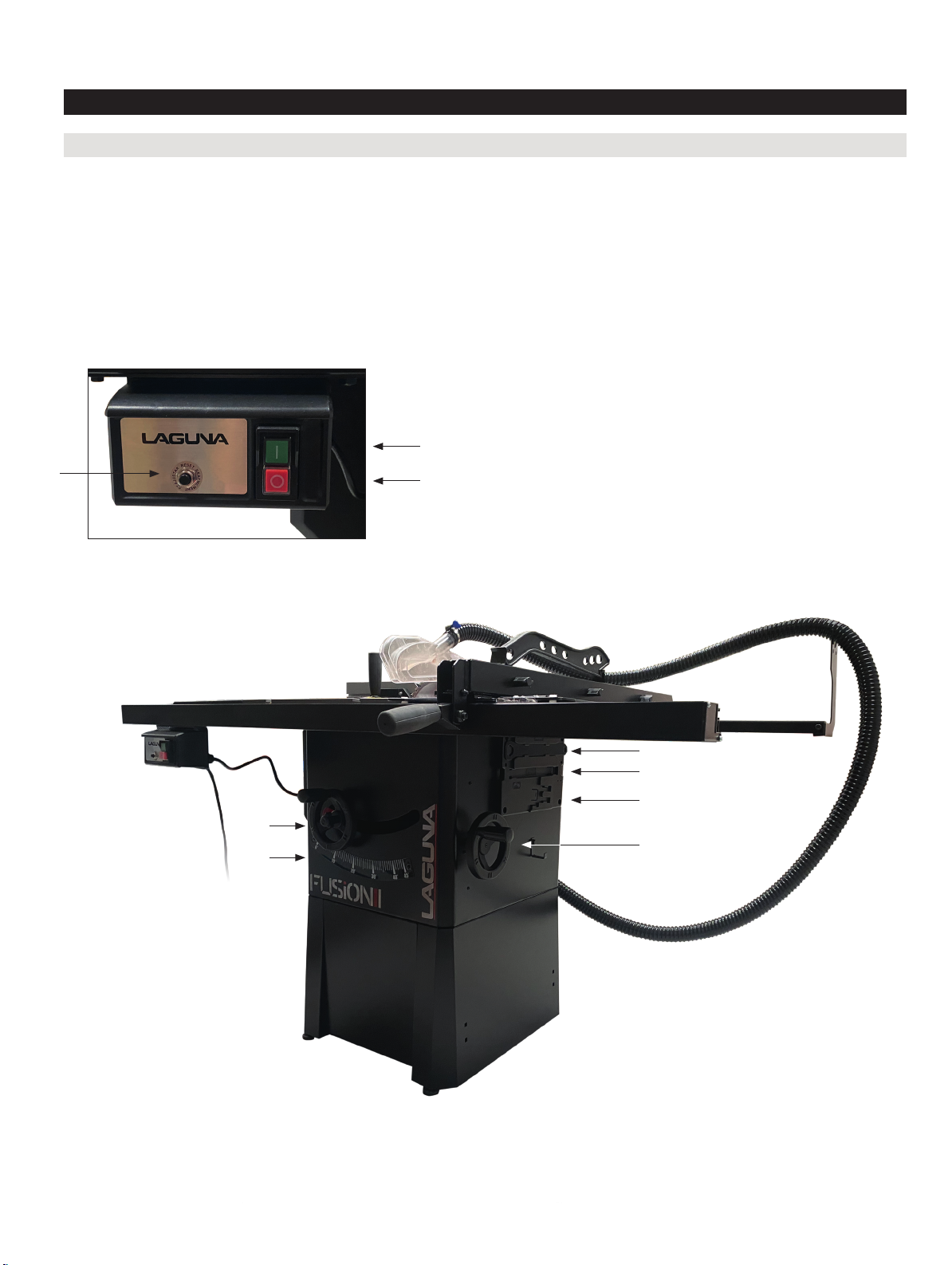
Fusion F1 Table Saw (MTSF132110150-0130)
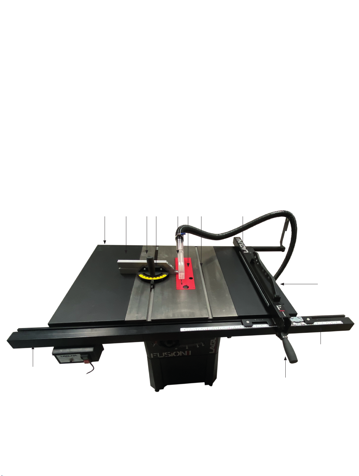
A. Motor Reset B. ON C. OFF D. Arbor Tilt Wheel
E. Blade Guard Storage F. Riving Knife Storage G. Miter Gauge Storage H. Blade Change Tool
I. Arbor Height Wheel J. Arbor Tilt Gauge K. 4” Dust Outlet L. Mobility Wheels
M. Motor Cover N. Rip Fence Storage O. Rear Fence Rail P. Wing
Q. Table R. Miter Gauge S. Blade Guard T. Throat Plate
U. Miter Slot V. Rip Fence W. Push Stick X. Front Fence Rail
Y. Fence Lock Z. Rip Fence Scale
B
A
C
H
G
E
I
D
J
19
8
Page 9
F1 Table Saw
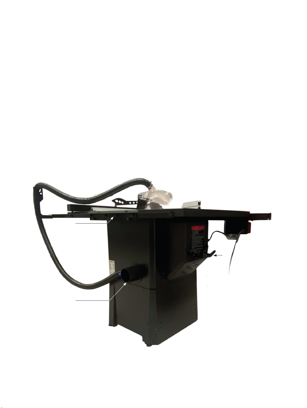
A. Motor Reset B. ON C. OFF D. Arbor Tilt Wheel
E. Blade Guard Storage F. Riving Knife Storage G. Miter Gauge Storage H. Blade Change Tool
I. Arbor Height Wheel J. Arbor Tilt Gauge K.4” Dust Outlet L. Mobility Wheels
M. Motor Cover N. Rip Fence Storage O. Rear Fence Rail P. Wing
Q. Table R. Miter Gauge S. Blade Guard T. Throat Plate
U. Miter Slot V. Rip Fence W. Push Stick X. Front Fence Rail
Y. Fence Lock Z. Rip Fence Scale
O
K
N
M
20
9
Page 10
F1 Table Saw
A. Motor Reset B. ON C. OFF D. Arbor Tilt Wheel
E. Blade Guard Storage F. Riving Knife Storage G. Miter Gauge Storage H. Blade Change Tool
I. Arbor Height Wheel J. Arbor Tilt Gauge K. 4” Dust Outlet L. Mobility Wheels
M. Motor Cover N. Rip Fence Storage O. Rear Fence Rail P.Wing
Q. Table R. Miter Gauge S. Blade Guard T. Throat Plate
U. Miter Slot V. Rip Fence W. Push Stick X. Front Fence Rail
Y. Fence Lock Z. Rip Fence Scale
O P Q R S T U
V
W
Z
X
21
10
Y
Page 11

F1 Table Saw
Setup Help Sections
Receiving
It is likely that your machine will be delivered by a third party. Before unboxing, be sure to inspect the
packaging and shipping documents supplied by the driver. Ensure that there is no visible damage to the
shipment. If any damage has occurred because of shipment, note the damage on the bill of lading or refuse
the shipment. Immediately call the dealer store where the machine was purchased.
1. Never accept a shipment that is damaged or partial without notifying the shipping company and the
purchasing store.
Placement
Prior to removing the machine from the packaging, decide the operating location of the machine. The
dimensions and floor space can be found here: Dimensions.
1. There should be sufficient area at the front of the machine to allow you to work on it comfortably.
2. There should be sufficient area at the back of the machine to allow access for adjustments and
maintenance to be conducted.
3. The better the lighting the more accurately and safely you will be able to work.
4. You should select a solid flat floor, preferably one made of concrete or something similar.
5. Locate it close to a power source and dust collection (if applicable).
Unboxing
Once in place, carefully unbox and remove all components. Unboxing guidelines:
1. Do not cut deep into a box with a blade as it could scratch the paint; only cut deep enough to cut the tape
or use a dull edge.
2. Prior to setting up the machine, organize all hardware and setup tools needed.
22
11
Page 12
F1 Table Saw
Base and cabinet
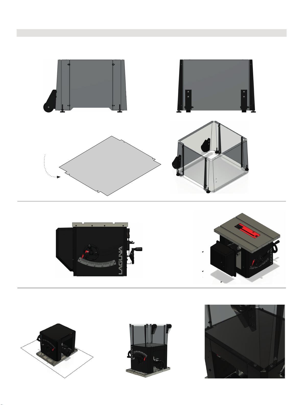
Setup the base according to the following diagram. If you purchased the wheels, now is a great time to
install them. They can go on the left or the right side, but it makes a lot more sense to put them on the left.
Please t the dust tray (part 141)
Before the nal assembly of the
machine onto the stand.
With the base put together, remove the motor cover of the saw body.
To bolt the base to the cabinet, make sure the saw blade and all spreaders are removed and lay the cabinet
on the cast iron top against some cardboard.
N.B. Mobility wheels shown in these pictures are not supplied with this machine
23
12
Page 13
F1 Table Saw
24
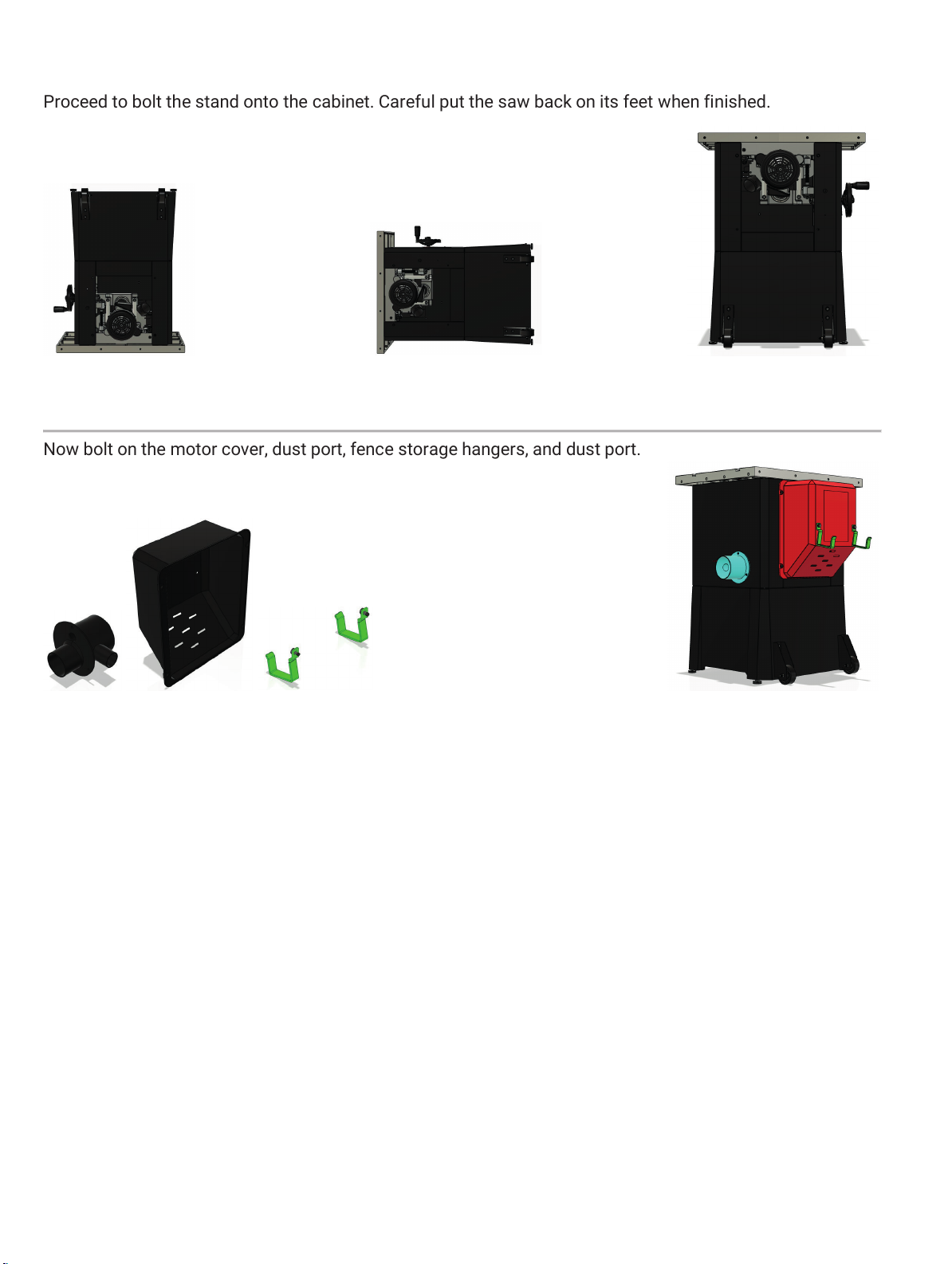
Proceed to bolt the stand onto the cabinet. Careful put the saw back on its feet when finished.
Now bolt on the motor cover, dust port, fence storage hangers, and dust port.
N.B. Mobility wheels shown in these pictures are not supplied with this machine
13
Page 14
Wings, Rails, & Fence
F1 Table Saw
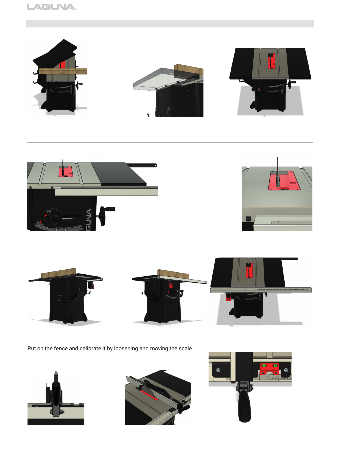
Put on the fence and calibrate it by loosening and moving the scale.
Attached the wings. Use a flat material to level and then bolt down.
Allign the front fence to the blade using the notch on the scale.
F1 Table Saw
Use a flat material to level and attatch the fence guides. Make sure to install the switch.
N.B. Mobility wheels shown in these pictures are not supplied with this machine
25
14
Page 15
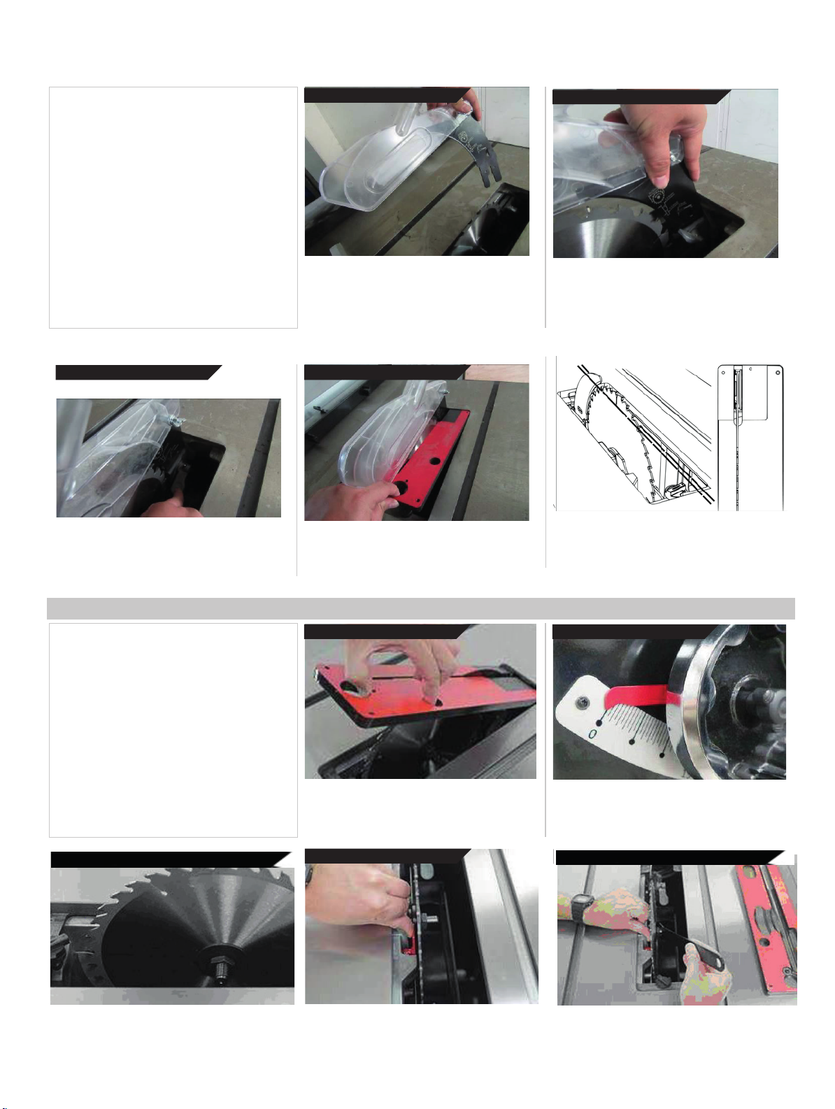
Installing/Removing the Blade
Guard
1. Un-plug the tablesaw!
2. Make sure the lock is in open position
3. Insert the blade guard
4. Position the guard insert
5. Lock the blade guard
6. Reinstall throat plate
CAUTION: Make sure the blade guard is inline with the blade. If it is not in line, please
see the Adjustments Section.
3.
insert the blade
WARNING: MAKE SURE SAW IS UNPLUGGED.
With the throat plate removed, and the cam lock
mechanism in the open position (pulled up), insert
the blade guard insert into the slot.
guard 4.
position
Hold up the pawls and position the blade guard
against the left inside of the casing and push down.
Slide the riving knife against the left inside
Make sure the guard is positioned correctly and
of the casing and push down. Make sure the
guard is positioned correctly and seated in
seated in the bottom of the casing. Grasp the
the bottom of the casing.
pawls with one hand, leaving the other hand
to activate the cam action lock.
TO
LEFT
OF CASING
free
5.
lock THE Blade
Keep firm hold of the blade guard with left hand
and engage the cam lock with the thumb of your
right hand.
Guard 6.
Reinstall the throat
Grasp the pawls up and out of the way to re-insert
the throat plate. Lock the throat plate.
Reinstall and lock the throat plate
plate
CAUTION: Make sure the riving knife is in-line with
the blade. If it is not in line, please see the
Adjustments Section.
Installing/Removing the Blade
2.
Remove
1. Un-plug the tablesaw!
2. Remove any blade guards, riving knifes,
splitters, and the throat plate to access the
blade.
3. Set the arbor tilt to 0 degrees and lock.
4. Raise saw to highest position.
5. Engage blade lock (red component).
6. Remove the arbor nut and flange with
arbor wrench.
7. Remove or install blade.
CAUTION: Make sure the teeth of the blade
are facing the front of the saw as shown.
WARNING: MAKE SURE SAW IS UNPLUGGED.
To access the blade remove all accessories
around the blade, including riving knifes, throat
plates, ect.
all accessories 3.
Set the arbor tilt to 0 degrees and lock the arbor to
prevent it from moving when installing or removing
blades.
Set arbor tilt
to 0
and
lock.
4.
Raise saw blade
4.Raise Sawblade to highest position
highest
pos.
to
5.
Engage the blade
lock
15
6. Remove arbour nut and flange
6.
Remove arbor nut and
flange
Page 16
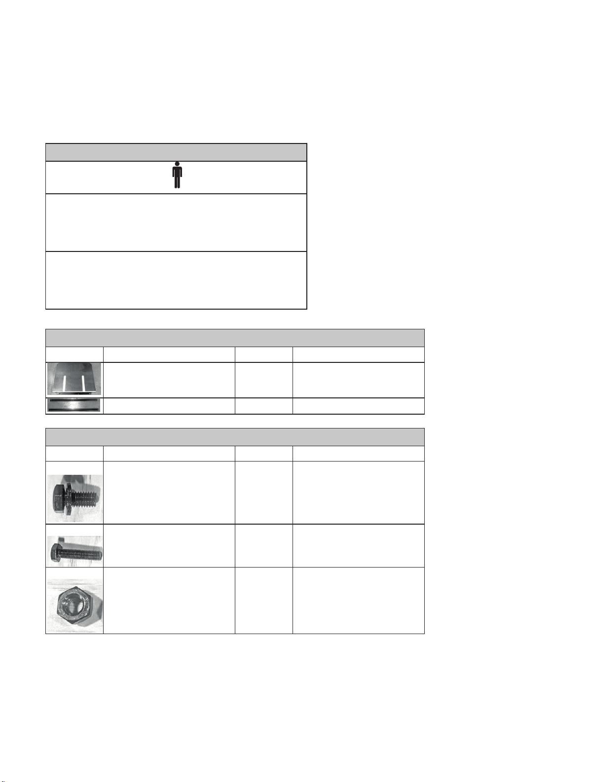
Rear Extension
Add. Required Tools:
the
rear
Hardware
Washer
The Fusion F1 table saw’s rear extension table supports both the fence and the work piece. In conjunction with the rear rail,
the rear extension table provides an extra support table for the length of the wood piece being cut.
Table
Quick Reference Guide
Level
General Wrench
17mm socket wrench (optional)
Troubleshooting/Tips:
For easiest assembly, flip the rear extension table so that
face is down. After the table has been flipped, attach the
extension legs to the table.
Parts
REF Description
Rear Extension Table
Rear Extension Table Legs
Q
Installation
1
2
Rear Rail Assembly, F1 Table
Rear Extension Table
REF Description
C
Hex Cap Screw w/ Flat
(longer)
I
J
Hex Cap Bolt (51mm)
use with Nylon Lock Nuts(H)
Nylon Lock Nuts (16mm)
Q
Installation
3 of 5
4 of 4
4 of 4
Rear Extension Table, F1 Table
Rear Extension Table Legs,
Rear Extension table
Rear Extension Table Legs,
Rear Extension table
16
Page 17
Rear Extension
Table
The Fusion F1 table saw’s rear extension table supports both the fence and the work piece. In conjunction with the rear rail,
the rear extension table provides an extra support table for the length of the wood piece being cut.
Quick Reference Guide
Add. Required Tools:
Level
General Wrench
17mm socket wrench (optional)
Troubleshooting/Tips:
For easiest assembly, flip the rear extension table so that the
face is down. After the table has been flipped, attach the rear
extension legs to the table.
Parts
REF
Description
Q Installation
Rear Extension Table
1
Rear Rail Assembly, F1 Table
Rear Extension Table Legs
2
Rear Extension Table
Hardware
REF
Description
Q Installation
C
Hex Cap Screw w/ Flat Washer
(longer)
3 of 5
Rear Extension Table, F1 Table
I
Hex Cap Bolt (51mm)
use with Nylon Lock Nuts(H)
4 of 4
Rear Extension Table Legs,
Rear Extension table
J
Nylon Lock Nuts (16mm)
4 of 4
Rear Extension Table Legs,
Rear Extension table
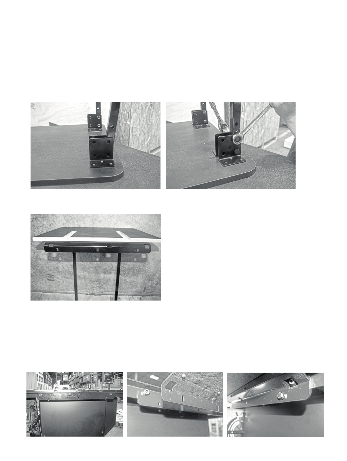
Attaching Legs to the Rear Extension Table:
aligned with the last two bolt holes of the metal bracket.
4.
Thread the 51 mm hex bolts through the metal L-bracket.
Pre-
installation
Aligning the bracket
1.
Flip the rear extension table so that the face is down.
2.
Place the rear extension legs between the metal L-brackets on either side of the table.
3.
Align the rear extension leg’s bolt holes with bracket’s bolt holes. Ensure that the rear extension leg’s bolt holes are
5.
Thread nylon lock nuts on to the back of the hex bolts. Tighten with a wrench or a 17 mm socket wrench (optional).
Attaching legs to table:
Installed
Legs
Securing
Bolts
Attaching the Rear Extension Table to the Table Saw:
1.
Locate the three through holes on the back mounting bracket of the rear extension table.
2.
Align these three through holes with the three threaded holes on the rear support bracket.
3.
Thread one of the three (longer) Hex Bolt with Flat Washer through each of the threaded holes.
NOTICE! The height of the rear extension table’s legs can be adjusted as needed to level the table.
Pre-
installation
Aligning the bracket
Bolt into thread holes:
17
Page 18
F1 Table Saw
Safety Device Alignment
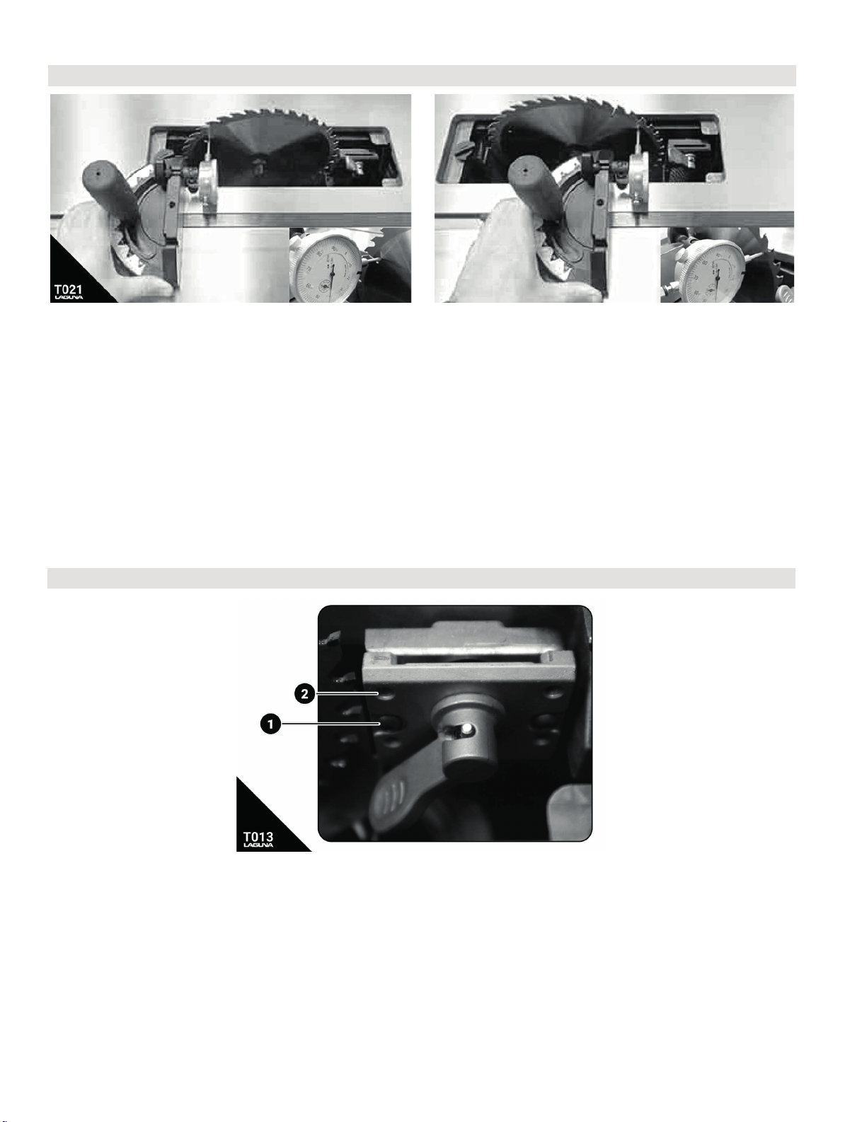
Fig T013: Safety Device adjustments. (1) locking bolts. (2) adjustment set screws.
The riving knife, blade guard, or splitter must be aligned with the blade to be used effectively. The riving
knife should only be used with blades specified on the riving knife (or vice versa). To adjust the position of
the blade safety attachments, relative to the saw blade:
• Loosen the two locking bolts. These two bolts fasten the assembly in-between the set screws and the
arbor block.
• Adjust the set screws as needed to correct the out-of-align blade attachment. Do small adjustments
and check.
Table/Blade/Fence Alignment
F1 Table Saw
Fig T021: Blade/Table alignment with mitre gauge and dial indicator.
It is good practice to make sure that the table is always parallel to the blade by checking it often. You can
do this with a combination square or with a dial indicator on an appropriate mount. There are several
dedicated tools to do this job well like the saw gauge.
With the throat plate and all attachments removed, raise the blade to the highest position at 90 degrees with
the table. Take an initial measurement about ½ inch from the ground edge of the blade as shown.
Keep the miter gauge against the left rail and slowly move across the blade. Take the second measurement
and compare with the initial measurement. Adjust the table to compensate false measurements. There are
3 bolts to loosen prior to adjusting the table.
Safety Device Alignment
Fig T013: Safety Device adjustments. (1) locking bolts. (2) adjustment set screws.
The riving knife, blade guard, or splitter must be aligned with the blade to be used effectively. The riving
knife should only be used with blades specified on the riving knife (or vice versa). To adjust the position of
the blade safety attachments, relative to the saw blade:
• Loosen the two locking bolts. These two bolts fasten the assembly in-between the set screws and the
arbor block.
• Adjust the set screws as needed to correct the out-of-align blade attachment. Do small adjustments
and check.
18
Page 19
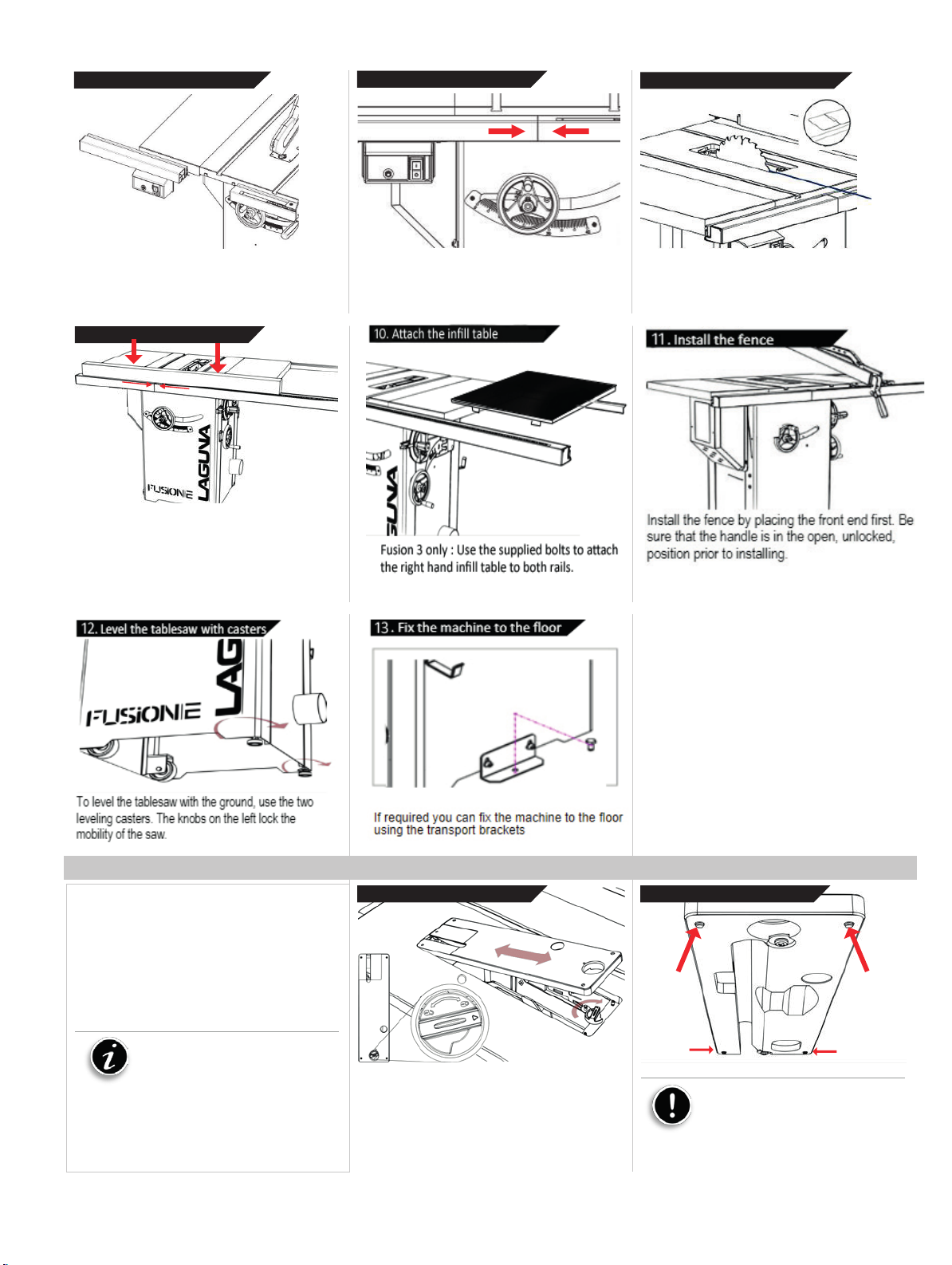
6.
Insert short rail and
switch 7.
Join front fence
supports 8.
Align the front rail with
blade
Adjust lock plate location and fix the machine on the
f
increase the chance of kickback.
Insert the short front rail into the first square head
bolt. IMPORTANT: Insert the switch assembly
before joining the two front rail pieces. STOP
BEFORE TIGHTENING.
9.
Level and fasten front
This step may take 2 persons. To level the front
rail sections to the table top, u
edge atop the loosely fit rail sections. Apply
downward force to the straight edge while keeping
the two sections firmly together. Simultaneously
fasten down the bolts.
12. Fix the machine to the floor
rail
se a ridged straight
Align the pins and join the two front rail pieces and
firmly push together.
Install the
10.
Install the fence by placing the front end first. Be
sure that the handle is in the open, unlocked,
position prior to installing.
fence
Using the blade notching on the measuring tape,
align the entire front rail section to the blade.
11.
Level the tablesaw with
To level the tablesaw with the ground, use the two
leveling casters. The knobs on the left lock the
mobility of the saw.
casters
*
If required you can fix the machine to the floor
using the transport brackets
loor by screw.
Installing/Removing the Throatplate
1. Un-plug the tablesaw!
2. Insert the throat plate back end first.
3. Lower the throatplate to the table.
4. Lock the throat plate with the thumb-lock.
5. Level the throatplate with the table using
the cat screws.
Notice: This machine is shipped
with a zero-clearance throat plate that
has already been cut at the factory.
Because of this, there may be some
residue already in the saw.
Installing the throat
WARNING: MAKE SURE SAW IS UNPLUGGED.
To remove or install the throat plate, first set it to
the unlock position. Then, insert the rear end first
and tilt the other en
plate
d down into position.
* N.B. Mobility wheels
shown in this picture are
Fusion 3 only
Leveling the throat
To level the throatplate, adjust the leveling screws.
Use
Caution: Make sure the throat
plate is lower than the cast iron table.
Having the throat plate higher at any
position can interfere with the workpiece
feed and cause injury or harm and
plate
19
Page 20
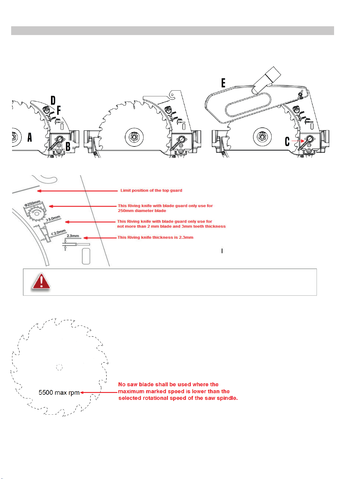
Warning: Since Riving Knife, other than those offered by Laguna, has not been tested with this product, use
Installing/Removing Safety Accessories
A: Saw
⚫
⚫
blade
block
B: Accessory insert
C: Cam action
lever
Note on the Riving Knife
D: Riving
E:
F:
knife
Guard
Blade
Blade Compliant
Markings
of such accessories with this tool could be hazardous. To reduce the risk of injury, only Laguna,
recommended accessories should be used with this product.
Note on the Blade
20
Page 21
F1 Table Saw
Daily Check:
Any other unsafe condition
Weekly Maintenance:
Monthly Maintenance:
Every 6–12 Months:
• Lubricate gearing and gearboxes.
Maintenance & Troubleshooting
Never perform and setup, maintenance or adjustment procedures with the machine connected
to the power source!
If you have any doubt about the described procedure, seek professional assistance. Do not
attempt any procedure that you feel is unsafe, or that you do not have the physical capability of achieving.
When removing banding, extreme caution must be used as the banding will spring when cut.
The machine is heavy. Ensure that you have enough people to do the job safely.
There may be sawdust in or around your new machine as a result of thorough testing.
General
Keep your machine clean. At the end of each day, clean the machine. Wood contains moisture, and if
sawdust or wood chips are not removed, they will cause rust. In general, we recommend that you only use a
Teflon-based lubricant on the saw. Regular oil attracts dust and dirt. Teflon lubricant tends to dry and has
less of a tendency to accumulate dirt and saw dust. Periodically check that all nuts and bolts are tight.
Drive belt
The drive belt should last for many years (depending on the usage) but needs to be inspected regularly for
cracks, cuts and general wear. If damage is found, replace the belt.
Bearings
All bearings are sealed for life and do not require any maintenance. If a bearing becomes faulty, replace it.
Rust
The saw is made from steel and cast iron. All non-painted surfaces will rust if not protected. It is
recommended that they be protected by applying wax or a Teflon- based lubricant to them.
• Loose mounting bolts
• Damaged saw blade
• Damaged riving knifes, splitters, or blade
g
uards
• Clean table surface and miter slot grooves
• Clean and protect cast iron table
• Clean rip fence
• Worn or damaged wires
•
• Clean/vacuum dust buildup from inside
cabinet and off motors.
• Check/replace belt for proper tension, damag
o
r wear
• Lubricate trunnion slides.
• Lubricate worm gear.
e
• Lubricate leadscrew.
27
21
Page 22

F1 Table Saw
Behavior
Possible Causes
Solutions
Machine will not
1. Start capacitor at fault.
1. Test/replace if faulty.
wiring.
Machine is
1. Motor or component loose.
1. Inspect/replace damaged bolts/nuts,
replacement.
Machine trips the
1. Feed rate/cutting speed too fast.
12. Plug/receptacle at fault.
1. Decrease feed rate/cutting speed.
10. Test/repair/replace.
T
he fusion 1 should not come out of square as the trunnion is bolted to the table. If the
procedure results in false measurement, please check the blade and arbor nut prior to any further
adjustments.
Troubleshooting
start or continues
to trip the breaker.
excessively loud or
is experiencing
excessive
vibration.
2. Motor connection wired wrong.
3. Wiring at fault.
4. Motor Start/Stop switch at fault.
. M
5
otor at fault.
6. Run capacitor at fault.
7. Wall circuit breaker tripped or at fault.
8. Power supply switched OFF or at
fault.
9. Plug/receptacle at fault or wired
incorrectly.
2. Blade at fault.
3. Motor mount loose/broken.
4. Machine incorrectly mounted.
5. Arbor pulley loose.
6. Belts worn or loose.
7. Pulley loose or at fault.
8. Arbor bearings at fault.
2. Correct motor wiring connections.
3. Check/fix broken, disconnected, or
corroded wires.
4.Replace switch.
5. Test/repair/replace.
6. Test/replace if faulty.
7. Ensure circuit size is correct/replac
eak breaker.
w
8. Ensure power supply is on/has
correct voltage.
9. Test wires and contacts; correct t
he
and re tighten with thread-locking fluid.
2. Replace warped/bent blade; re-
sharpen dull blade.
3. Tighten/replace.
4. Tighten mounting bolts;
relocate/shim machine.
5. Re-tighten/replace arbor pulley.
6. Adjust tension of/replace belt.
7. Realign/replace shaft, pulley,
setscrew, and key.
8a. Replace arbor housing bearings;
replace arbor.
8b. Test by rotating shaft;
grinding/loose shaft requires bearing
e
overload, or feels
underpowered
during operation.
2. Workpiece material unsuitable for
machine.
3. Pulley/sprocket slipping on shaft.
4. Motor bearings at fault.
5. Contactor (internal breaker) at fault.
6. Motor overheated.
7. Workpiece crooked; fence not
aligned.
8. Machine undersized for task; wrong
blade.
9. Run capacitor at fault.
10. Belt is slipping from pulley.
11. Motor wired incorrectly.
22
2. Only cut wood; ensure moisture is
below 20%.
3. Test for good contacts/correct wiring.
4. Replace loose pulley/shaft.
5. Test/repair/replace.
6. Test all legs for power/replace if
faulty.
7. Clean motor, let cool, and reduce
workload.
8. Straighten or replace workpiece;
adjust fence.
9. Use correct blade; reduce feed rate or
depth of cut.
29
Page 23
F1 Table Saw
13. Motor at fault.
11. Adjust tension of/replace belt.
12. Wire motor correctly.
13. Test/repair/replace.
Dust Collection
1. Inadequate suction
1. The optional zero clearance throat
shroud port and the external 4" port.
F1 Table Saw
2. No suction
plate will supply better dust collection
than the standard die cast throat plate.
2. move motor cover and verify that the
internal hose is fixed to the blad
e
Wiring
VOLTAGE. Before connecting this tool to a power supply (receptacle, outlet, etc.) make sure that
the voltage supplied is the same that is specified on the nameplate of the tool. IF IN DOUBT, DO NOT PLUG
IN THE MACHINE. Using this tool with a voltage different than that stated on the nameplate can damage the
electrical components of this machine and any such damage will not be covered by a warranty.
CIRCUIT BREAKER. Also make sure that the power supply is equipped with the appropriate
breaker and plug according to your local electrical code. To do this, first check the motor plate to get the
FLA amperage of the machine, if worn out or not present then refer to the specifications sheet. If there is
any doubt in regards to choosing the appropriate circuit breaker, please consult an electrician or an
electrical supply source.
ELECTRICAL SHOCK. It is extremely dangerous to work on live wires and/or electrical systems
that are connected to a power source. ALWAYS disconnect the power from the machine prior to performing
any maintenance or adjustments.
MOTOR WIRING: The information in this manual was current at the time of printing but may be
different than the diagram on your machine. ALWAYS use the supplied wiring diagram with the machine or
motor (under the electrical covering) if present.
30
23
Page 24
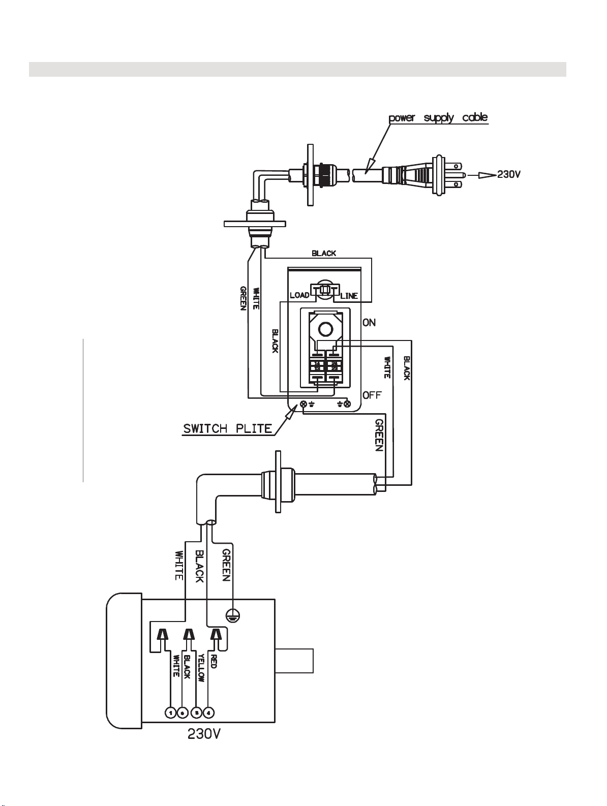
F1 Table Saw
Wiring
VOLTAGE. Before connecting this tool to a power supply (receptacle, outlet, etc.) make sure that
the voltage supplied is the same that is specified on the nameplate of the tool. IF IN DOUBT, DO NOT PLUG
IN THE MACHINE. Using this tool with a voltage different than that stated on the nameplate can damage the
electrical components of this machine and any such damage will not be covered by a warranty.
CIRCUIT BREAKER. Also make sure that the power supply is equipped with the appropriate
breaker and plug according to your local electrical code. To do this, first check the motor plate to get the
FLA amperage of the machine, if worn out or not present then refer to the specifications sheet. If there is
any doubt in regards to choosing the appropriate circuit breaker, please consult an electrician or an
electrical supply source.
ELECTRICAL SHOCK. It is extremely dangerous to work on live wires and/or electrical systems
that are connected to a power source. ALWAYS disconnect the power from the machine prior to performing
any maintenance or adjustments.
MOTOR WIRING: The information in this manual was current at the time of printing but may be
different than the diagram on your machine. ALWAYS use the supplied wiring diagram with the machine or
motor (under the electrical covering) if present.
F1 Table Saw
Fusion F1 Table Saw (MTSF132110150-0130)
24
31
Page 25
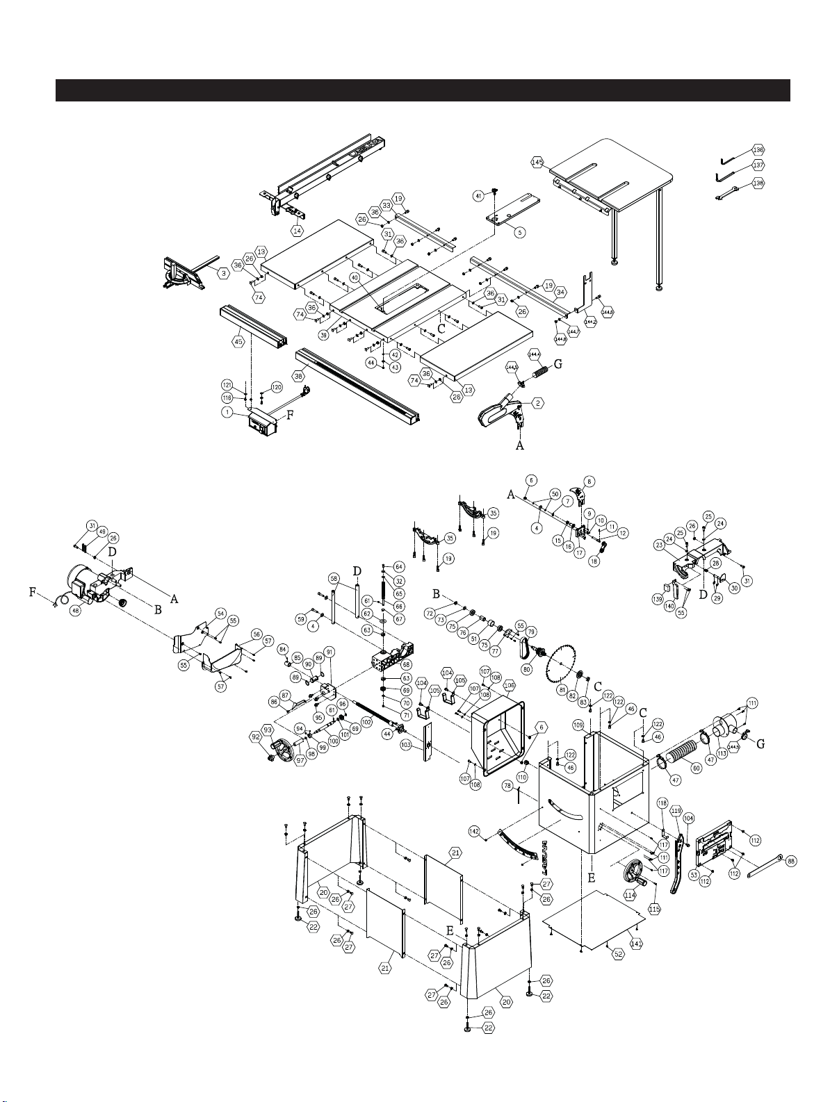
Parts
F1 Table Saw
25
Page 26
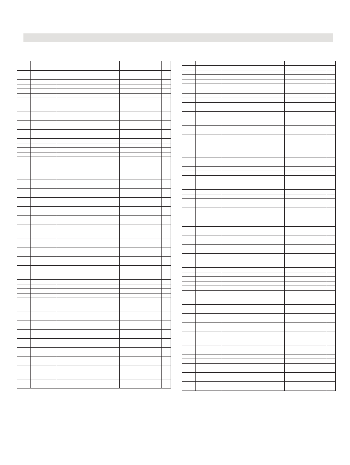
Fusion F1 Table Saw Parts Table (MTSF132110150-0130)
11. Parts list
F1 Table Saw
Key Part No. Descriptions Specification Q'ty
1 938128-001 Magnetic Switch Assembly KJD-17-230V 1
2 924708-001 Blade Guard Assembly 1
3 924710-001 Miter Gauge Assembly 1
4 006001-045 Flat Washer 8.5*16*1.0t 3
5 924793-001 Table Insert Assembly 1
6 008306-100 Lock Nut M8*1.25P(13B*9H) 3
7 010005-000 Retaining Ring STW-14 1
9 001902-710 SET Lock Screw M6*1.0P*8 4
10 000804-105 Round Head Screw M5*0.8P*20 2
11 361251-905 Pin 1
12 361250-901 Fixing Knob 1
13 925201-001 Extension Table Assembly 2
14 925205-001 Fence Assembly 1
15 280259-901 Spring 1
16 130363-903 Bushing 1
17 110073-000 Bracket for Riving Knife 1
18 110071-000 Lock Handle 1
19 001803-103 CAP Screw w/ Spring Washer M8*1.25P*25/8.2*13.7 12
20 924629-001 Stand 2
21 924630-001 Stand Connect Plate 2
22 230109-615 Leveling Foot 4
23 090323-000 Upper Trunnion 1
24 006305-100 Spring Washer 8.2*13.7 2
25 002601-102 Locking CAP screw M8*1.25P*20 2
26 008006-100 Hex. Nut M8*1.25P(13B*6.5H) 34
27 001001-101 Shoulder Screw M8*1.25P*16 16
28 280260-901 Spring 1
29 010206-000 Retaining Ring ETW-9 2
30 174716-019 Arbor Lock Handle 1
31 000104-106 Cap Screw M8*1.25P*20 10
36 006001-049 Flat Washer 8.5*16*2.0t 20
32 006001-020 Flat Washer 6.2*20*3.0t 1
33 924631-001 Rear Rail-L Assembly 1
34 924632-001 Rear Rail-R Assembly 1
35 110020-000 Trunnion Support 2
38 925204-001 Front Rail (R) Assembly 1
39 051464-000 Table 1
40 011001-103 Spring Pin 3*10 1
41 251358-615 Knob 1
42 006701-100 Wave Washer WW-6 1
43 006001-137 Flat Washer 5.3*16*1.5t 1
44 008302-100 Lock Nut M5*0.8P(8B*6H) 3
45 924576-001 Front Rail (L) Assembly 1
46 000104-103 Cap Screw M8*1.25P*12 4
47 042608-000 Clamp 60-80mm(I.D.) 2
48 901311-001
381483-902 1
49 280266-000 Spring 1
50 006702-100 Wave Washer WW-8 2
51 361473-901 Spacer 1
52 001104-703 Round Hear Tapping Screw M5*2.12P*12 4
53 251251-615 #NENÍ_K_DISPOZICI 1
54 174773-000 Fixing Plate 1
55 002503-101 Round Head Socket Lock Screw M5*0.8P*12 8
56 251398-615 Dust Hood 1
57 002002-101 Round Head Phillip Screw M5*0.8P*8 5
58 361246-000 Column 2
59 002601-108 Locking CAP screw M8*1.25P*35 2
60 042620-017 Dust Hose 2.5”(I.D.)*500mm 1
61 012002-003 Key 4*4*8 2
62 174324-000 Washer 1
63 031011-001 Bearing 51100 2
64 000002-103 Hex. Screw M6*1.0P*16 1
65 006007-114 Flat Washer 6.4*16*1.6t() 1
66 361245-901 Lead Screw 1
67 010007-000 Retaining Ring STW-16 1
68 090324-000 #NENÍ_K_DISPOZICI 1
69 130257-000 Bevel Gear 2
70 006001-025 Flat Washer 6.4*16*1.0t 1
71 008317-300 Lock Nut M6*1.0P(10B*5H) 1
1100W*230V*50HZ*1PH
72 008316-200 Lock Nut M10*1.5P(17B*8H) 1
73 006001-075 Flat Washer 10.3*22*2.0t 1
74 048701-101 Square Screw M8*1.25P*20 6
92 920703-001 Fixing Knob 1
97 250406-615 Bushing 1
115 001801-102 CAR Screw w/Spring Washer
119 251362-615 Push Sticks 1
136 040002-000 Hex. Wrench 2.5mm 1
137 040004-000 Hex. Wrench 4mm 1
138 174569-904 Open Wrench 10*13 1
104 049201-101 Hex. Screw w/Flat Washer
105 170541-904 Slide Shelf 2
75 030211-002 Ball Bearing 6003 2
76 190270-901 Spacer 1
77 174305-901 Fixed Plate 1
78 230297-615 Fixed Chain 1
79 014360-000 Poly-V-Belt 139J-7(PU-Bando) 1
80 361351-902 Arbor 1
81 390040-000 Saw Blade 250mm x 30mm x 40T 1
82 130388-000 Sawblade Clamp 1
83 380205-901 Nut TW5/8"-12(in) 1
84 001902-109 SET Lock Screw M6*1.0P*6 1
85 130377-903 Stop Ring 1
86 002402-101 Round Head Lock Screw w/Washer
87 174464-156 Pointer 1
88 174315-904 Arbor Wrench 1
89 010011-000 Retaining Ring STW-25 2
90 361290-902 Guide Shaft 1
91 174465-904 Leading Shaft Bracket 1
93 920715-002 Handwheel Assembly of Up-Down 1
94 000202-101 SET Screw M5*0.8P*5 2
95 001501-101
96 010001-000 Retaining Ring STW-10 1
98 043322-000 O-Ring P11 1
99 190273-901 Bushing 1
100 361273-902 Shaft 1
101 006001-078 Flat Washer 10.5*19*1.5t 1
102 924513-001 Lead Screw Assembly 1
103 173370-901 Fixed Plate 1
104 049201-101 Hex. Screw w/Flat Washer
106 251239-615 Motor Cover 1
107 000304-107 Pan Head Screw M6*1.0P*16 4
1
108 006001-022 Flat Washer 6.3*13*1.0t 4
109 174527-000 Cabinet 1
110 020002-000 Strain Relief SB7R-1 1
111 000303-104 Pan Head Screw M5*0.8P*12 5
112 001603-102 Round Head Screw w/Washer
113 251418-615 Adaptor 1
114 920718-002 Handwheel Assembly of Angel 1
116 000002-101 Hex. Screw M6*1.0P*12 2
117 001103-901 Round Hear Tapping Screw M4.5*1.81P*9 4
118 170965-904 Fix Plate 1
120 006001-033 Flat Washer 6.7*16*1.0t 2
121 008603-100 Square Screw M6*1.0P(10B*5H) 2
122 006504-100 Tooth Washer 8.4*15(BW-8) 4
139 200108-000 Sponge 1
140 174772-000 Chip Guard 1
142 001601-101 Round Head Screw w/Washer M4*0.7P*8/4*10*0.8t 2
144 924854-001 Over Head Guards Assembly 36" 1
144.1 042620-015 Dust Hose 1.5”(I.D.)*2700mm() 1
144.2 174887-904 Brace 1
144.5 042622-003 Clamp 30-45mm(I.D.) 2
144.6 001803-103 CAP Screw w/ Spring Washer M8*1.25P*25/8.2*13.7 1
144.7 006001-049 Flat Washer 8.5*16*2.0t 1
144.8 008006-100 Hex. Nut M8*1.25P(13B*6.5H) 1
145 925202-001 Rear Table Assembly 1
Cap Screw w/Lock Washer&Flat
Washer
M5*0.8P*12-5.1*9.3*1.3t
M8*1.25P*16/
(13B*6.5H)
M5* 0.8P* 12/5* 10.5*
1.0t
M8* 1.25P* 20/8.2*
13.7/8.5* 19* 2t
M8*1.25P*16/
(13B*6.5H)
M6* 1.0P* 10/6* 13.2*
1.0t
1
2
1
3
1
4
26
Page 27

Laguna Tools Inc.
UK DE
Product model: F1 Fusion Table Saw
Name and address of the manufacturer: Laguna Tools Inc. 2072 Alton Parkway, Irvine, California
92606, USA.
Name and address of the UK Authorised Representative: Axminster Tool Centre Ltd, Unit 10 Weycroft
Avenue, Axminster, Devon EX13 5PH, United Kingdom.
This declaration of conformity is issued under the sole responsibility of the manufacturer.
Object of the declaration: F1 Fusion Table Saw
The object of the declaration described above is in conformity with the relevant GB legislation:
Supply of Machinery (Safety) Regulations 2008 as amended.
Electromagnetic Compatibility Regulations 2016 as amended.
References to the relevant harmonised standards used or references to the other technical
specifications in relation to which conformity is declared:
CLARATION OF CONFORMITY
‘original’
EN ISO 12100:2010 Safety of Machinery. General principles for design. Risk assessment and
risk reduction.
ISO 19085-9:2020 Woodworking machines - Safety - Part 9: Circular saw benches (with and
without sliding table) (ISO 19085-9:2019)
EN 60204-1:2018 Safety of machinery - Electrical equipment of machines - Part 1: General
requirements (IEC 60204-1:2016, modified)
Additional information:
Name and address of person authorised to compile the technical file: Axminster Tool Centre
Ltd, Unit 10 Weycroft Avenue, Axminster, Devon EX13 5PH, United Kingdom
The machinery fulfils all relevant provisions of Supply of Machinery (Safety) Regulations 2008
as amended.
Signed for and behalf of: Axminster Tool Centre Ltd.
(place and date of issue): Axminster, Devon, United Kingdom, 20
(name, function):
Andrew Parkhouse, Supply Chain Director
th
June 2024
Signature:
27
27
Page 28

28
Page 29

Warranty
New machines and accessories sold by Laguna Tools carry a one-year
warranty effective from the date of shipping.
Laguna Tools guarantees all new machines and accessories sold to be
free of manufacturers’ defective workmanship, parts and materials.
We will repair or replace, without charge, any parts determined by
Laguna Tools, Inc. to be a manufacturer’s defect.
We require that the defective item/part be returned to the Laguna
appointed dealer you purchased from with the complaint. Photographic / videos maybe required when any fault is reported so we can
agree action needed. Any machines returned to Laguna appointed dealer must be returned with packaging in the same manner
in which it was received. If a part or blade is being returned it must
have adequate packaging to ensure no damage is received during
shipping. In the event the item/part is determined to be damaged
due to lack of maintenance, cleaning or misuse/abuse, the customer
will be responsible for the cost to replace the item/part, plus all related shipping charges. This limited warranty does not apply to natural
disasters, acts of terrorism, normal wear and tear, product failure due
to lack of maintenance or cleaning, damage caused by accident,
neglect, lack of or inadequate dust collection, misuse/abuse or damage caused where repair or alterations have been made or attempted
by others. Laguna Tools, Inc. is not responsible for additional tools or
modifications sold or performed (other than from/by Laguna Tools,
Inc.) on any Laguna Tools, Inc. machine.
Warranty maybe voided upon the addition of such described tools
and/or modifications, determined on a case-by-case basis.
Normal user alignment, adjustment, tuning, machine settings and
consumables I.E; blades are not covered by this warranty. It is the
responsibility of the user to understand basic machinery operation,
settings and procedures and to properly maintain the equipment in
accordance with the standards provided by the manufacturer.
The labour required to install replacement parts is the responsibility
of the user. Laguna Tools is not responsible for damage or loss caused
by a freight company or other circumstances not in our control.
All claims for loss or damaged goods must be notified to the authorised dealer within twenty-four hours, if the machine is received damaged it must be signed for damaged.
Only new machines sold to the original owner are covered by this
warranty.
29
Page 30

F1 Table Saw
Laguna takes pride in our products and stands behind them with continuing service and support for our customers. Your Laguna machine was
designed to bring a new dimension of productivity to your shop.
Before using your machine for the first time, learn how to use it. This manual covers a step-by-step process of assembly and machine operation. If
you have any questions, this manual will provide answers.
We do our best to thoroughly document every product that we sell for customer reference. Several files are compiled to cover all components of a
machine.
Several machines may be covered by one manual.
Many machines sold by Laguna include components with independent owners’ manuals.
Owner’s Manuals
Owners’ manuals will guide the purchasing party
Warranty - All information about warranty, how to file a warranty claim, and how-to receiver support.
Safety - The safety related rules and guidelines set forth by the manufacturing parties to be strictly followed in the operation of the machine or
product.
Set Up - Guidelines to set-up the product from state of shipping to state of operation.
Operation - Procedure based sections covering the basic process that the machine or product was designed to do.
Maintenance - Maintenance Schedule and procedures that must be followed.
Troubleshooting - Procedure based help sections to repair an out of service machine or product.
Parts - A list of replacement parts offered for the Machine. This section may not include all the parts included with the purchase – if the part was not
included in this section then it will be available from a third party.
Schematics – Line drawings of electrical, pneumatic, and dimensional configurations of the machine or product.
Specification Sheets
Specification Sheets will aid in proper machine selection and serve as a reference for the purchasing party. For convenience, the specifications
sheet has been included in the end of this manual.
Description - A detailed description of why the machine was developed,
General Specifications - All specifications that are common to all machine categories.
Category Specifications - Specifications unique to the specific category of the machine.
Dimensional Drawing
Capacities Drawing
Accessories, Options, and Consumables
Videos
In most cases a video is the best media to cover a setup or help topic.
All videos made by Laguna are uploaded and stored to youtube.com where they are then linked to websites.
https://www.youtube.com/user/LagunaTools
Websites
Websites holds all information about our product range. Check it often for any updates to your machine. As innovation happens, that is where you
will find it.
lagunatools.com
lagunatools.ca
lagunatools.eu
supermaxtools.com
lagunacleanair.com
lagunalathe.com
The information contained in this publication was correct at the time of print. In the interest of continuous innovation, we reserve the right to change
specifications, design or included equipment without notice or obligation. No part of this publication may be reproduced, transmitted, or translated
into any language in any form by any means without our written permission. Errors and omissions may be current.
Laguna Tools, Inc. LAGUNA® and the LAGUNA Logo® are the registered trademarks of Laguna Tools, Inc. All rights reserved. 04/01/2019
2072 Alton Parkway Irvine, CA 92606 U.S.A.
S
ervice: +1 (949) 474-1200 or email [email protected]
lagunatools.com
2
30
Page 31

31
Page 32

Distributed by
The packaging is suitable for recycling.
Please dispose of it in a responsible manner.
EU Countries Only
Do not dispose of electric tools together with household waste material.
By law they must be collected and recycled separately.
For after sales help visit
axminstertools.com or call 03332 406406
Axminster Tools, Axminster Devon EX13 5PH
 Loading...