

Page 1
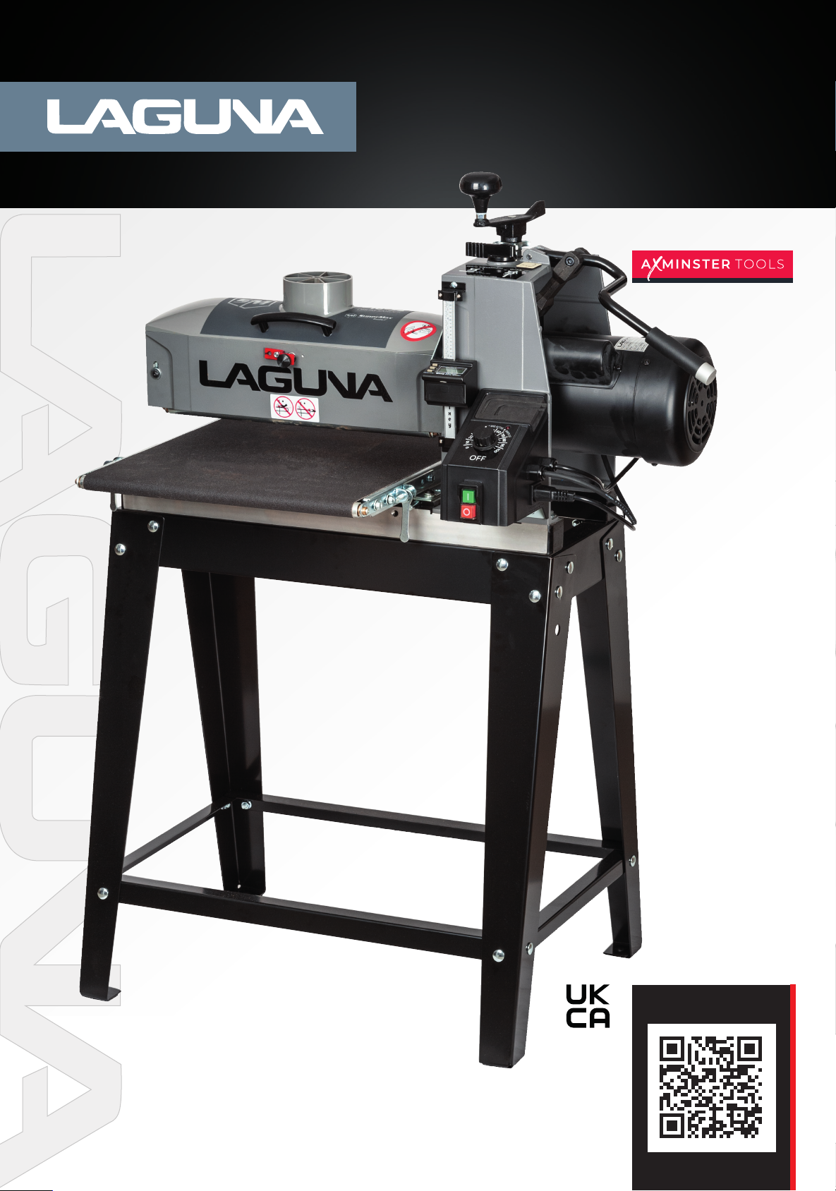
16|32 Sander 230v
Code: 111781
Distributed by
N.B. Some pictures and diagrams in this manual may have buttons and electrical configurations
which differ slightly from the machine you purchased
Version: 2
Date: 1/10/25
DIGITAL MANUAL
Page 2

Contents
Safety Rules 3
Noise Emissions 4
Specifications 6
About The Supermax Tools Drum Sander 6
Unpacking Your Drum Sander 6
Assembling Your Tools Drum Sander 7
Installing Your Tools Drum Sander 9
Setting Up Your Supermax Tools Drum Sander 10
Abrasive Selection Guide 12
Operating Your Drum Sander 14
Maintenance 18
Supply Checklist 19
Troubleshooting Your Supermax Tools Drum Sander 20
Wiring Diagram 22
Parts List And Diagrams 23
Conformity Certificates 29
Warranty 31
2
Page 3
SAFETY RULES
1. KEEP GUARDS IN PLACE and in working order.
2. REMOVE ADJUSTING KEYS AND WRENCHES.
Form habit of checking to see that keys and ad-
justing wrenches are removed from tool before
turning it on.
3. KEEP WORK AREA CLEAN. Cluttered areas and
benches invite accidents.
4. DON'T USE IN DANGEROUS ENVIRONMENT.
Don't use power tools in damp or wet locations,
or expose them to rain. Keep work area well
lighted.
5. KEEP CHILDREN AWAY. All visitors should be
kept safe distance from work area.
6. MAKE WORKSHOP CHILD PROOF with padlocks,
master switches, or by removing starter keys.
7. DON'T FORCE TOOL. It will do the job better and
safer at the rate for which it was designed.
8. USE RIGHT TOOL. Don't force tool or attachment
to do a job for which it was not designed.
9. USE PROPER EXTENSION CORD. Make sure
your extension cord is in good condition. When
using an extension cord, be sure to use one
heavy enough to carry the current your product
will draw. An undersized cord will cause a drop
in line voltage resulting in loss of power and
overheating. Table A (on the next page) shows
the correct size to use depending on cord length
and nameplate ampere rating. If in doubt, use
the next heavier gage. The smaller the gage nu-
mber, the heavier the cord.
10. WEAR PROPER APPAREL. Do not wear loose
clothing, gloves, neckties, rings, bracelets, or
other jewelry which may get caught in moving
parts. Nonslip footwear is recommended. Wear
protective hair covering to contain long hair.
11. ALWAYS USE SAFETY GLASSES. Also use face
or dust mask if cutting operation is dusty. Eve-
ryday eyeglasses only have impact resistant
lenses, they are NOT safety glasses.
12. SECURE WORK. Use clamps or a vise to hold
work when practical. It's safer than using your
hand and it frees both hands to operate tool.
13. DON'T OVERREACH. Keep proper footing and
balance at all times.
14. MAINTAIN TOOLS WITH CARE. Keep tools sharp
and clean for best and safest performance. Fol-
low instructions for lubricating and changing ac-
cessories.
15. DISCONNECT TOOLS before servicing; when
changing accessories, such as blades, bits, cut-
ters, and the like.
16. REDUCE THE RISK OF UNINTENTIONAL STA-
TING. Make sure switch is in off position before
plugging in.
17. USE RECOMMENDED ACCESSORIES. Consult
the owner's manual for recommended acces-
sories. The use of improper accessories may
cause risk of injury to persons.
18. NEVER STAND ON TOOL. Serious injury could
occur if the tool is tipped or if the cutting tool is
unintentionally contacted.
19. CHECK DAMAGED PARTS. Before further use of
the tool, a guard or other part that is damaged
should be carefully checked to determine that
it will operate properly and perform its intended
function - check for alignment of moving parts,
binding of moving parts, breakage of parts,
mounting, and any other conditions that may
affect its operation. A guard or other part that
is damaged should be properly repaired or re-
placed.
20. DIRECTION OF FEED. Feed work into a blade or
cutter against the direction of rotation of the
blade or cutter only.
21. NEVER LEAVE TOOL RUNNING UNATTENDED.
TURN POWER OFF. Don't leave tool until it co-
mes to a complete stop.
Some dust created by power sanding, sawing, grinding, drilling and other construction activities contain chemicals
known to cause cancer, birth defects or other reproductive harm. Some examples of these chemicals are:
• Lead from lead based paint.
• Crystalline silica from bricks, cement, and other masonry products.
• Arsenic and chromium from chemically treated lumber.
Your risk of exposure varies, depending on how often you do this type of work. To reduce your exposure to these
chemicals, work in a well-ventilated area and work with approved safety equipment, such as face or dust masks
that are specically designed to lter out microscopic particles.
3
Page 4
P2
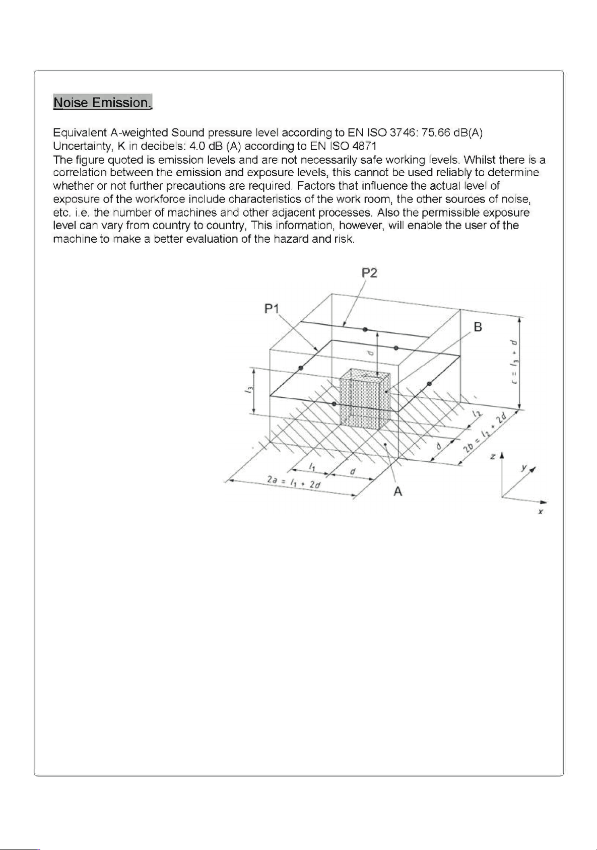
4
Page 5
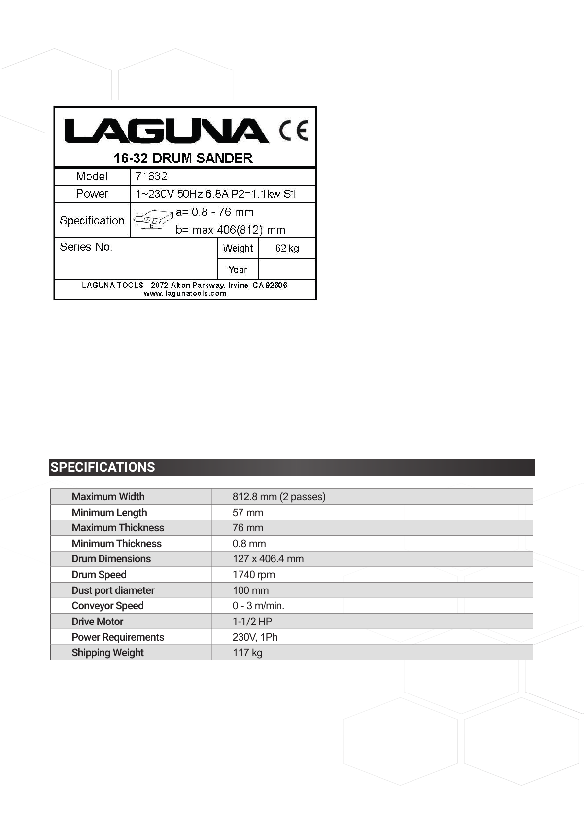
SPECIFICATIONS
Maximum Width 812.8 mm (2 passes)
Minimum Length 57 mm
Maximum Thickness 76 mm
Minimum Thickness 0.8 mm
Drum Dimensions 127 x 406.4 mm
Drum Speed 1740 rpm
Dust port diameter 100 mm
Conveyor Speed 0 - 3 m/min.
Drive Motor 1-1/2 HP
Power Requirements 230V, 1Ph
Shipping Weight 117 kg
METAL SCREW
OUTLET BOX
COVER OF GROUNDED
OUTLET BOX
GROUDING PIN
GROUDING PIN
5
Page 6
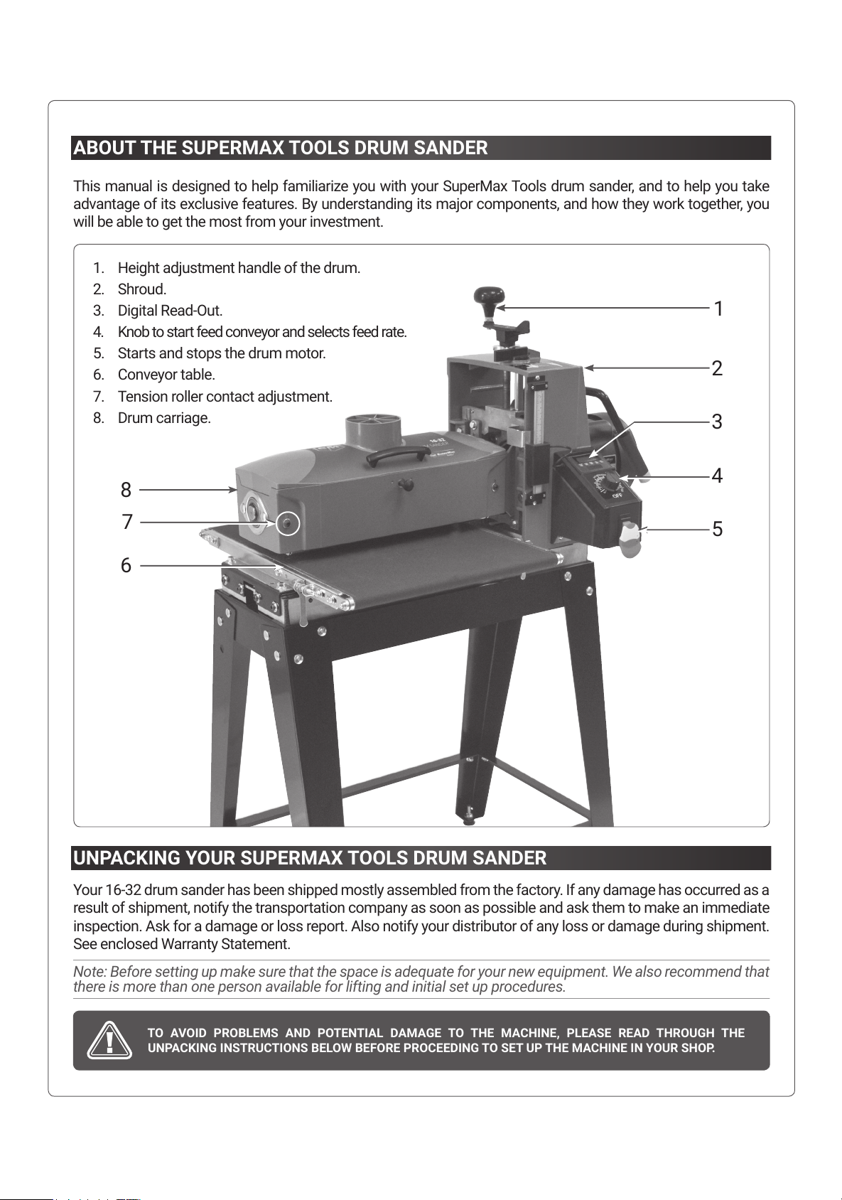
ABOUT THE SUPERMAX TOOLS DRUM SANDER
This manual is designed to help familiarize you with your SuperMax Tools drum sander, and to help you take
advantage of its exclusive features. By understanding its major components, and how they work together, you
will be able to get the most from your investment.
UNPACKING YOUR SUPERMAX TOOLS DRUM SANDER
Your 16-32 drum sander has been shipped mostly assembled from the factory. If any damage has occurred as a
result of shipment, notify the transportation company as soon as possible and ask them to make an immediate
inspection. Ask for a damage or loss report. Also notify your distributor of any loss or damage during shipment.
See enclosed Warranty Statement.
Note: Before setting up make sure that the space is adequate for your new equipment. We also recommend that
there is more than one person available for lifting and initial set up procedures.
TO AVOID PROBLEMS AND POTENTIAL DAMAGE TO THE MACHINE, PLEASE READ THROUGH THE
UNPACKING INSTRUCTIONS BELOW BEFORE PROCEEDING TO SET UP THE MACHINE IN YOUR SHOP.
1
3
4
5
7
6
8
2
1. Height adjustment handle of the drum.
2. Shroud.
3. Digital Read-Out.
4. Knob to start feed conveyor and selects feed rate.
5. Starts and stops the drum motor.
6. Conveyor table.
7. Tension roller contact adjustment.
8. Drum carriage.
6
Page 7
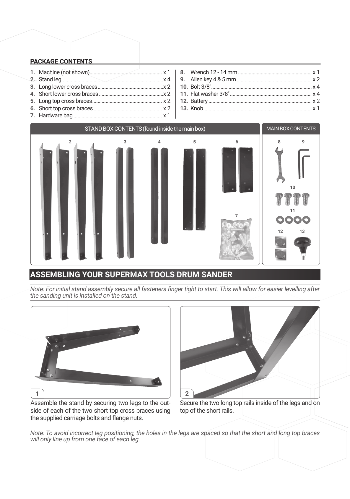
PACKAGE CONTENTS
ASSEMBLING YOUR SUPERMAX TOOLS DRUM SANDER
Note: For initial stand assembly secure all fasteners nger tight to start. This will allow for easier levelling after
the sanding unit is installed on the stand.
Note: To avoid incorrect leg positioning, the holes in the legs are spaced so that the short and long top braces
will only line up from one face of each leg.
1. Machine (not shown) ...................................................... x 1
2. Stand leg ............................................................................x 4
3. Long lower cross braces .................................................x 2
4. Short lower cross braces ................................................x 2
5. Long top cross braces .................................................... x 2
6. Short top cross braces ................................................... x 2
7. Hardware bag .................................................................. x 1
8. Wrench 12 - 14 mm ....................................................... x 1
9. Allen key 4 & 5 mm ....................................................... x 2
10. Bolt 3/8"...................................................... ..................... x 4
11. Flat washer 3/8" ............................................................. x 4
12. Battery ............................................................................. x 2
13. Knob ................................................................................. x 1
Assemble the stand by securing two legs to the out-
side of each of the two short top cross braces using
the supplied carriage bolts and flange nuts.
Secure the two long top rails inside of the legs and on
top of the short rails.
1 2
2 53 4 6
78
7
89
10
11
12 13
STAND BOX CONTENTS (found inside the main box)
MAIN BOX CONTENTS
7
Page 8
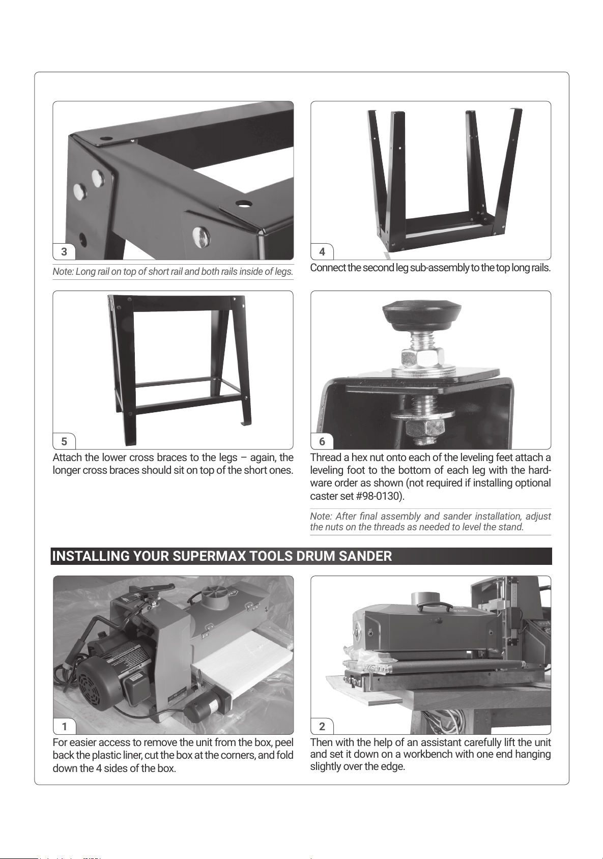
Connect the second leg sub-assembly to the top long rails.
Note: Long rail on top of short rail and both rails inside of legs.
3
For easier access to remove the unit from the box, peel
back the plastic liner, cut the box at the corners, and fold
down the 4 sides of the box.
Then with the help of an assistant carefully lift the unit
and set it down on a workbench with one end hanging
slightly over the edge.
INSTALLING YOUR SUPERMAX TOOLS DRUM SANDER
1 2
Attach the lower cross braces to the legs – again, the
longer cross braces should sit on top of the short ones.
Thread a hex nut onto each of the leveling feet attach a
leveling foot to the bottom of each leg with the hard-
ware order as shown (not required if installing optional
caster set #98-0130).
Note: After nal assembly and sander installation, adjust
the nuts on the threads as needed to level the stand.
5 6
4
8
Page 9
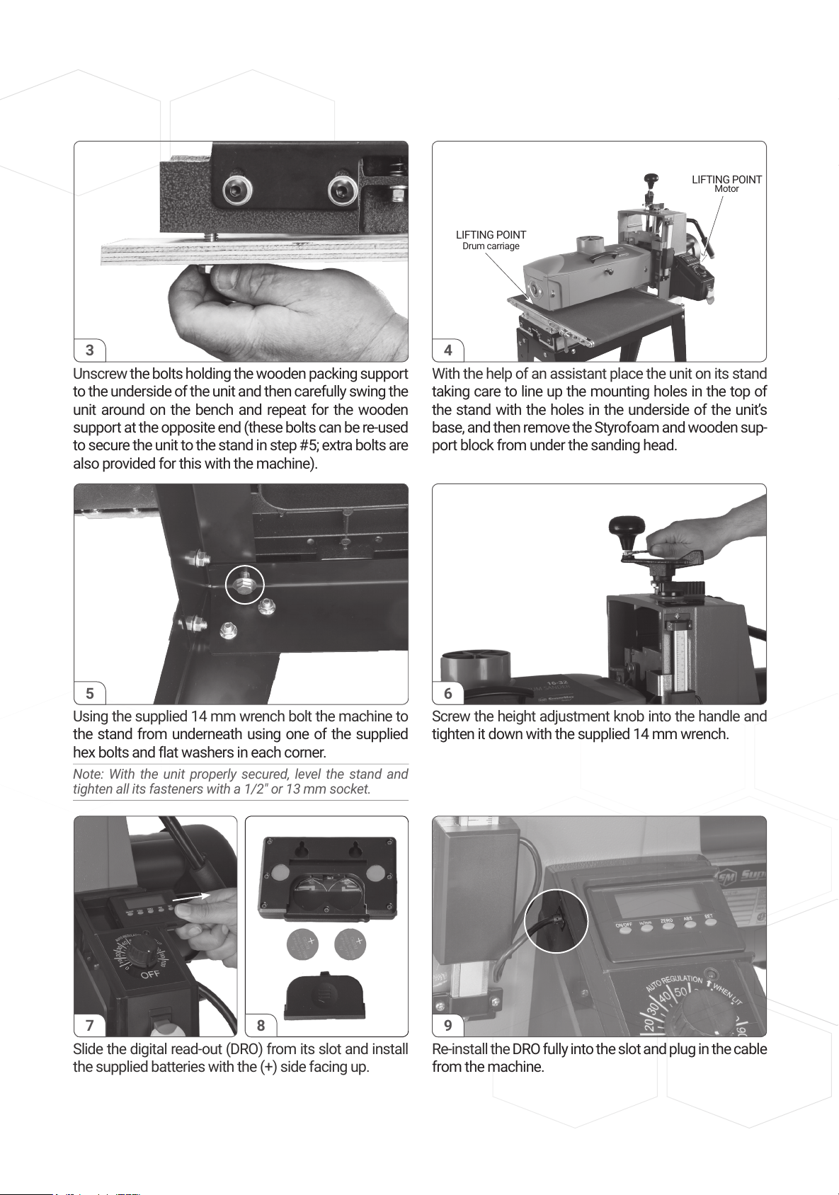
Unscrew the bolts holding the wooden packing support
to the underside of the unit and then carefully swing the
unit around on the bench and repeat for the wooden
support at the opposite end (these bolts can be re-used
to secure the unit to the stand in step #5; extra bolts are
also provided for this with the machine).
With the help of an assistant place the unit on its stand
taking care to line up the mounting holes in the top of
the stand with the holes in the underside of the unit’s
base, and then remove the Styrofoam and wooden sup-
port block from under the sanding head.
3
Using the supplied 14 mm wrench bolt the machine to
the stand from underneath using one of the supplied
hex bolts and flat washers in each corner.
Note: With the unit properly secured, level the stand and
tighten all its fasteners with a 1/2" or 13 mm socket.
Screw the height adjustment knob into the handle and
tighten it down with the supplied 14 mm wrench.
5 6
Slide the digital read-out (DRO) from its slot and install
the supplied batteries with the (+) side facing up.
Re-install the DRO fully into the slot and plug in the cable
from the machine.
7 8 9
4
LIFTING POINT
LIFTING POINT
Motor
Drum carriage
9
Page 10
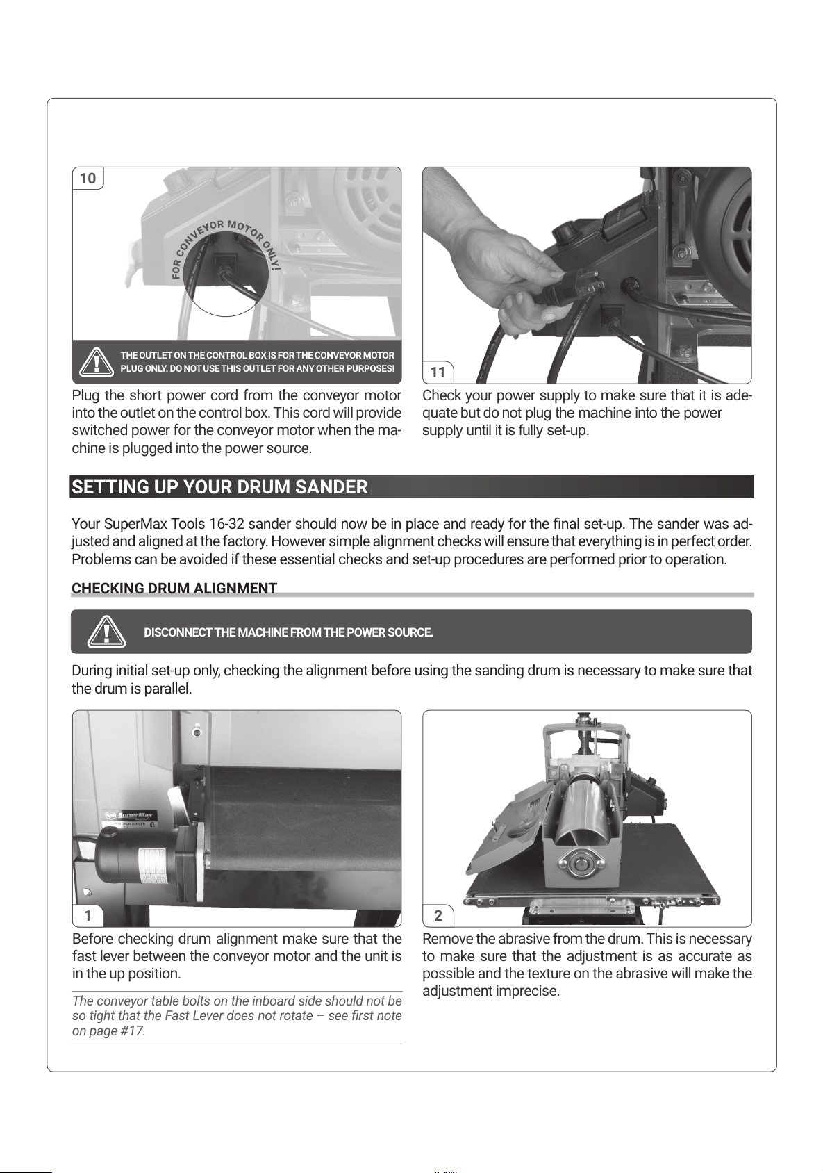
Plug the short power cord from the conveyor motor
into the outlet on the control box. This cord will provide
switched power for the conveyor motor when the ma-
chine is plugged into the power source.
Check your power supply to make sure that it is ade-
quate but do not plug the machine into the power
supply until it is fully set-up.
11
SETTING UP YOUR DRUM SANDER
Your SuperMax Tools 16-32 sander should now be in place and ready for the nal set-up. The sander was ad-
justed and aligned at the factory. However simple alignment checks will ensure that everything is in perfect order.
Problems can be avoided if these essential checks and set-up procedures are performed prior to operation.
CHECKING DRUM ALIGNMENT
During initial set-up only, checking the alignment before using the sanding drum is necessary to make sure that
the drum is parallel.
Remove the abrasive from the drum. This is necessary
to make sure that the adjustment is as accurate as
possible and the texture on the abrasive will make the
adjustment imprecise.
Before checking drum alignment make sure that the
fast lever between the conveyor motor and the unit is
in the up position.
The conveyor table bolts on the inboard side should not be
so tight that the Fast Lever does not rotate – see rst note
on page #17.
1 2
DISCONNECT THE MACHINE FROM THE POWER SOURCE.
10
THE OUTLET ON THE CONTROL BOX IS FOR THE CONVEYOR MOTOR
PLUG ONLY. DO NOT USE THIS OUTLET FOR ANY OTHER PURPOSES!
f
o
r
c
o
n
v
e
y
o
r
m
o
t
o
r
o
n
l
y
!
10
Page 11
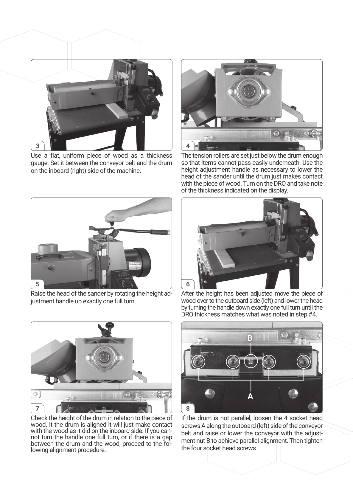
Use a flat, uniform piece of wood as a thickness
gauge. Set it between the conveyor belt and the drum
on the inboard (right) side of the machine.
The tension rollers are set just below the drum enough
so that items cannot pass easily underneath. Use the
height adjustment handle as necessary to lower the
head of the sander until the drum just makes contact
with the piece of wood. Turn on the DRO and take note
of the thickness indicated on the display.
3
Raise the head of the sander by rotating the height ad-
justment handle up exactly one full turn.
After the height has been adjusted move the piece of
wood over to the outboard side (left) and lower the head
by turning the handle down exactly one full turn until the
DRO thickness matches what was noted in step #4.
5 6
4
Check the height of the drum in relation to the piece of
wood. It the drum is aligned it will just make contact
with the wood as it did on the inboard side. If you can-
not turn the handle one full turn, or if there is a gap
between the drum and the wood, proceed to the fol-
lowing alignment procedure.
If the drum is not parallel, loosen the 4 socket head
screws A along the outboard (left) side of the conveyor
belt and raise or lower the conveyor with the adjust-
ment nut B to achieve parallel alignment. Then tighten
the four socket head screws
7 8
B
A
11
Page 12
POWER AND ELECTRICAL SAFETY
The SuperMax Tools 16-32 drum sander requires 230V, single-phase service. After the dust collection sys-
tem is in place and the drum alignment is checked your machine should be ready to be powered up and operated.
ABRASIVE SELECTION GUIDE
To attach a strip to the drum, follow the procedure below.
GRIT COMMON APPLICATION
36 GRIT Abrasive planing, surfacing rough-sawn boards, maximum stock or glue removal
60 GRIT Surfacing and dimensioning boards, trueing warped boards
80 GRIT Light dimensioning, removal of planer ripples
100 GRIT Light surfacing, removal of planer ripples
120 GRIT Light surfacing, minimal stock removal
150 GRIT Finish sanding, minimal stock removal
180 GRIT Finish sanding only, not for stock removal
220 GRIT Finish sanding only, not for stock removal
Note: See page #20 for complete list of pre-cut abrasives offered by SuperMax Tools for this specic unit.
CONNECTING DUST COLLECTORS
Dust collection is necessary for the SuperMax Tools 16-32 drum sander. The sander comes equipped with a
100 mm diameter dust exhaust port at the top of the cover. Check to make sure that the minimum dust
requirements are suf.cient. To attach to your collection system, install 100 mm hose from your collector. The
minimum recommended dust collector capacities is 600 cfm. For best results, follow the recommendations of the
manufacturer of your dust collection equipment. When connecting dust collectors straight pipe is preferred
because it is the least restrictive for airflow. If straight pipe is not possible Y’s and elbows are preferred because
they are less restrictive to airflow than T’s.
Note: Some applications will require more dust collection than the recommended minimum.
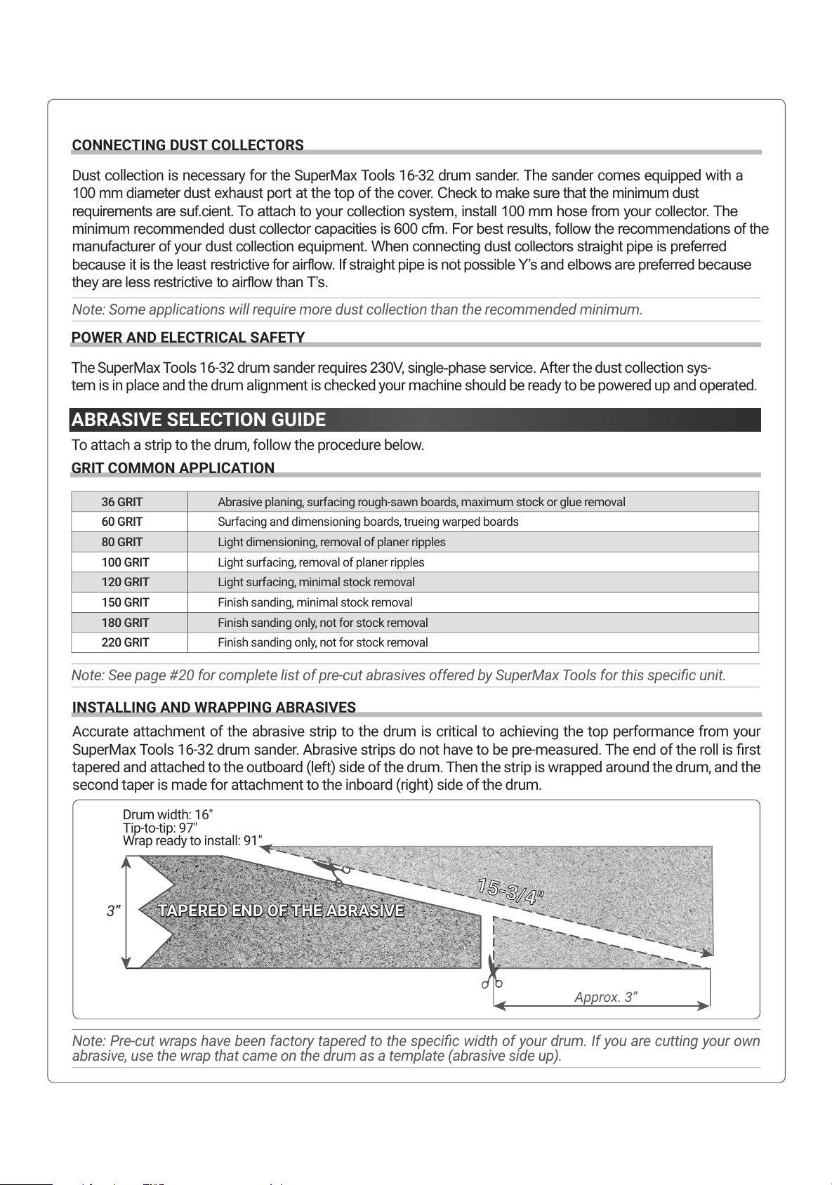
INSTALLING AND WRAPPING ABRASIVES
Accurate attachment of the abrasive strip to the drum is critical to achieving the top performance from your
SuperMax Tools 16-32 drum sander. Abrasive strips do not have to be pre-measured. The end of the roll is rst
tapered and attached to the outboard (left) side of the drum. Then the strip is wrapped around the drum, and the
second taper is made for attachment to the inboard (right) side of the drum.
Note: Pre-cut wraps have been factory tapered to the specic width of your drum. If you are cutting your own
abrasive, use the wrap that came on the drum as a template (abrasive side up).
Approx. 3’’
Bande abrasive (côté abrasif vers le haut)
3’’
15-3/4
"
TAPERED END OF THE ABRASIVE
Drum width: 16"
Tip-to-tip: 97"
Wrap ready to install: 91"
12
Page 13
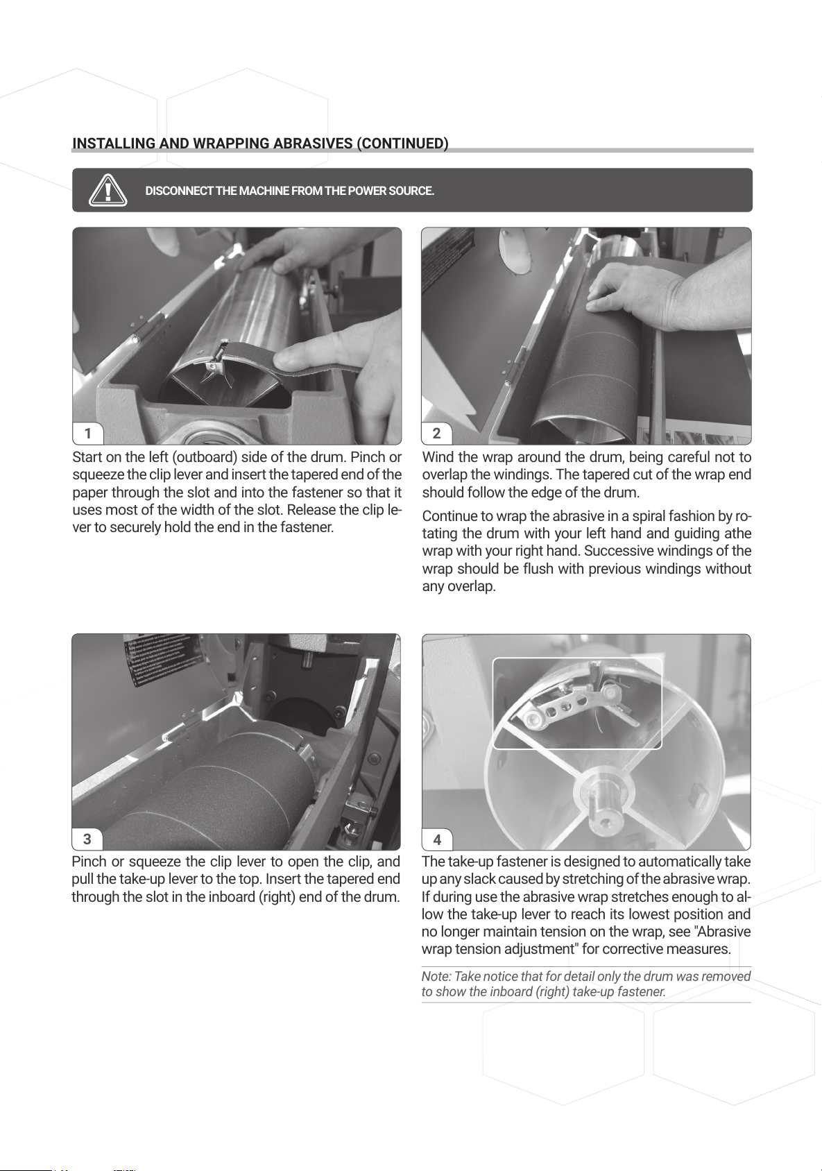
INSTALLING AND WRAPPING ABRASIVES (CONTINUED)
Pinch or squeeze the clip lever to open the clip, and
pull the take-up lever to the top. Insert the tapered end
through the slot in the inboard (right) end of the drum.
The take-up fastener is designed to automatically take
up any slack caused by stretching of the abrasive wrap.
If during use the abrasive wrap stretches enough to al-
low the take-up lever to reach its lowest position and
no longer maintain tension on the wrap, see "Abrasive
wrap tension adjustment" for corrective measures.
Note: Take notice that for detail only the drum was removed
to show the inboard (right) take-up fastener.
3
Start on the left (outboard) side of the drum. Pinch or
squeeze the clip lever and insert the tapered end of the
paper through the slot and into the fastener so that it
uses most of the width of the slot. Release the clip le-
ver to securely hold the end in the fastener.
Wind the wrap around the drum, being careful not to
overlap the windings. The tapered cut of the wrap end
should follow the edge of the drum.
Continue to wrap the abrasive in a spiral fashion by ro-
tating the drum with your left hand and guiding athe
wrap with your right hand. Successive windings of the
wrap should be flush with previous windings without
any overlap.
1 2
DISCONNECT THE MACHINE FROM THE POWER SOURCE.
4
13
Page 14
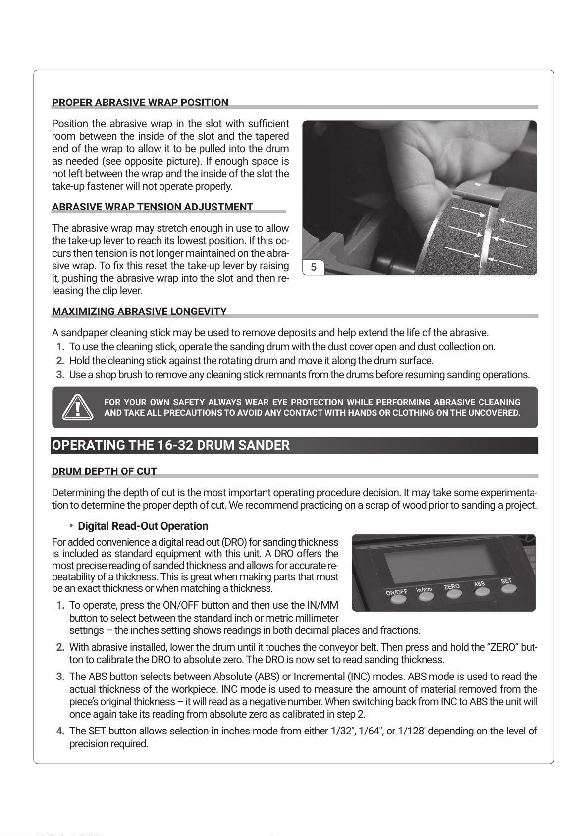
PROPER ABRASIVE WRAP POSITION
Position the abrasive wrap in the slot with sufcient
room between the inside of the slot and the tapered
end of the wrap to allow it to be pulled into the drum
as needed (see opposite picture). If enough space is
not left between the wrap and the inside of the slot the
take-up fastener will not operate properly.
ABRASIVE WRAP TENSION ADJUSTMENT
The abrasive wrap may stretch enough in use to allow
the take-up lever to reach its lowest position. If this oc-
curs then tension is not longer maintained on the abra-
sive wrap. To x this reset the take-up lever by raising
it, pushing the abrasive wrap into the slot and then re-
leasing the clip lever.
MAXIMIZING ABRASIVE LONGEVITY
A sandpaper cleaning stick may be used to remove deposits and help extend the life of the abrasive.
1. To use the cleaning stick, operate the sanding drum with the dust cover open and dust collection on.
2. Hold the cleaning stick against the rotating drum and move it along the drum surface.
3. Use a shop brush to remove any cleaning stick remnants from the drums before resuming sanding operations.
OPERATING THE 16-32 DRUM SANDER
DRUM DEPTH OF CUT
Determining the depth of cut is the most important operating procedure decision. It may take some experimenta-
tion to determine the proper depth of cut. We recommend practicing on a scrap of wood prior to sanding a project.
• Digital Read-Out Operation
For added convenience a digital read out (DRO) for sanding thickness
is included as standard equipment with this unit. A DRO offers the
most precise reading of sanded thickness and allows for accurate re-
peatability of a thickness. This is great when making parts that must
be an exact thickness or when matching a thickness.
1. To operate, press the ON/OFF button and then use the IN/MM
button to select between the standard inch or metric millimeter
settings – the inches setting shows readings in both decimal places and fractions.
2. With abrasive installed, lower the drum until it touches the conveyor belt. Then press and hold the “ZERO” but-
ton to calibrate the DRO to absolute zero. The DRO is now set to read sanding thickness.
3. The ABS button selects between Absolute (ABS) or Incremental (INC) modes. ABS mode is used to read the
actual thickness of the workpiece. INC mode is used to measure the amount of material removed from the
piece’s original thickness – it will read as a negative number. When switching back from INC to ABS the unit will
once again take its reading from absolute zero as calibrated in step 2.
4. The SET button allows selection in inches mode from either 1/32", 1/64", or 1/128' depending on the level of
precision required.
FOR YOUR OWN SAFETY ALWAYS WEAR EYE PROTECTION WHILE PERFORMING ABRASIVE CLEANING
AND TAKE ALL PRECAUTIONS TO AVOID ANY CONTACT WITH HANDS OR CLOTHING ON THE UNCOVERED.
5
14
Page 15
OPERATING THE 16-32 DRUM SANDER (CONTINUED)
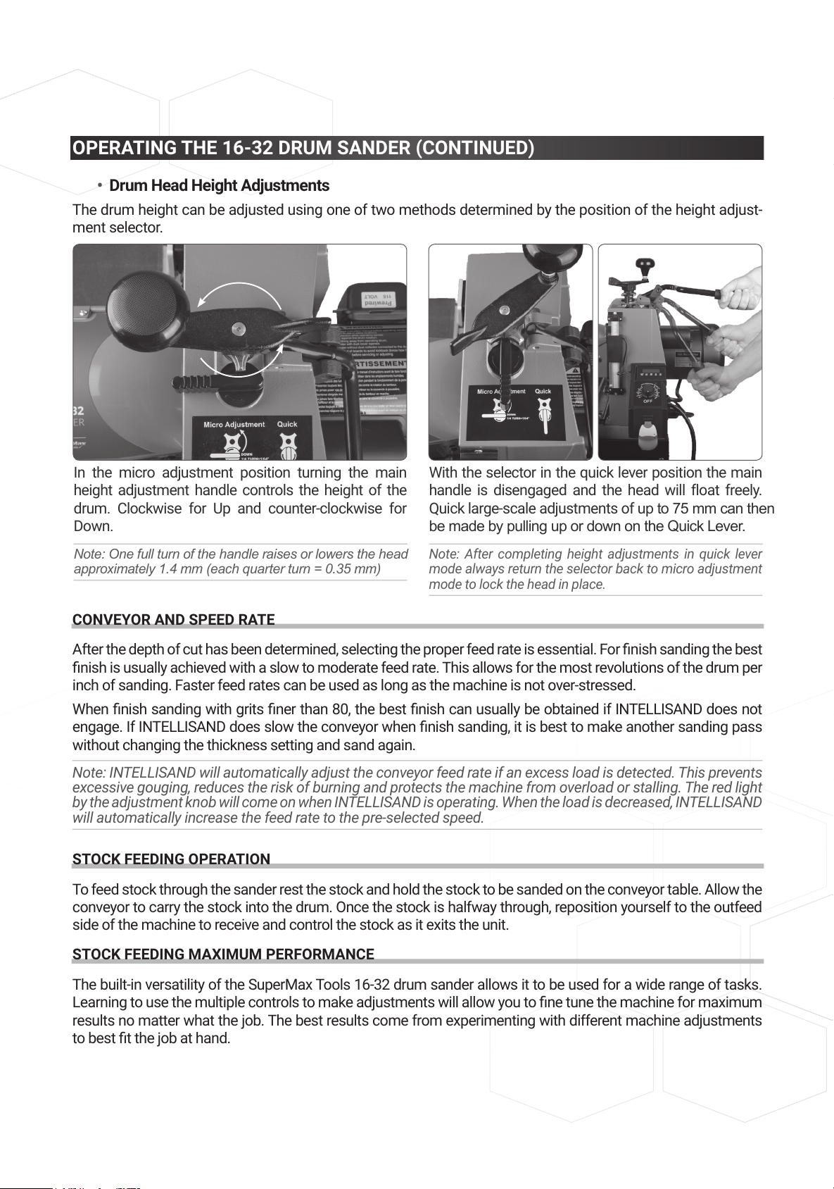
• Drum Head Height Adjustments
The drum height can be adjusted using one of two methods determined by the position of the height adjust-
ment selector.
CONVEYOR AND SPEED RATE
After the depth of cut has been determined, selecting the proper feed rate is essential. For nish sanding the best
nish is usually achieved with a slow to moderate feed rate. This allows for the most revolutions of the drum per
inch of sanding. Faster feed rates can be used as long as the machine is not over-stressed.
When nish sanding with grits ner than 80, the best nish can usually be obtained if INTELLISAND does not
engage. If INTELLISAND does slow the conveyor when nish sanding, it is best to make another sanding pass
without changing the thickness setting and sand again.
Note: INTELLISAND will automatically adjust the conveyor feed rate if an excess load is detected. This prevents
excessive gouging, reduces the risk of burning and protects the machine from overload or stalling. The red light
by the adjustment knob will come on when INTELLISAND is operating. When the load is decreased, INTELLISAND
will automatically increase the feed rate to the pre-selected speed.
STOCK FEEDING OPERATION
To feed stock through the sander rest the stock and hold the stock to be sanded on the conveyor table. Allow the
conveyor to carry the stock into the drum. Once the stock is halfway through, reposition yourself to the outfeed
side of the machine to receive and control the stock as it exits the unit.
STOCK FEEDING MAXIMUM PERFORMANCE
The built-in versatility of the SuperMax Tools 16-32 drum sander allows it to be used for a wide range of tasks.
Learning to use the multiple controls to make adjustments will allow you to ne tune the machine for maximum
results no matter what the job. The best results come from experimenting with different machine adjustments
to best t the job at hand.
With the selector in the quick lever position the main
handle is disengaged and the head will float freely.
Quick large-scale adjustments of up to 75 mm can then
be made by pulling up or down on the Quick Lever.
Note: After completing height adjustments in quick lever
mode always return the selector back to micro adjustment
mode to lock the head in place.
In the micro adjustment position turning the main
height adjustment handle controls the height of the
drum. Clockwise for Up and counter-clockwise for
Down.
Note: One full turn of the handle raises or lowers the head
approximately 1.4 mm (each quarter turn = 0.35 mm)
15
Page 16
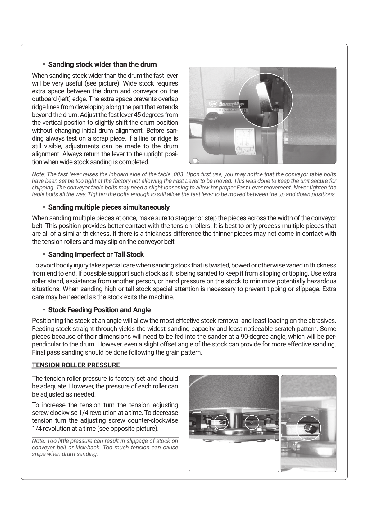
• Sanding stock wider than the drum
When sanding stock wider than the drum the fast lever
will be very useful (see picture). Wide stock requires
extra space between the drum and conveyor on the
outboard (left) edge. The extra space prevents overlap
ridge lines from developing along the part that extends
beyond the drum. Adjust the fast lever 45 degrees from
the vertical position to slightly shift the drum position
without changing initial drum alignment. Before san-
ding always test on a scrap piece. If a line or ridge is
still visible, adjustments can be made to the drum
alignment. Always return the lever to the upright posi-
tion when wide stock sanding is completed.
Note: The fast lever raises the inboard side of the table .003. Upon rst use, you may notice that the conveyor table bolts
have been set be too tight at the factory not allowing the Fast Lever to be moved. This was done to keep the unit secure for
shipping. The conveyor table bolts may need a slight loosening to allow for proper Fast Lever movement. Never tighten the
table bolts all the way. Tighten the bolts enough to still allow the fast lever to be moved between the up and down positions.
• Sanding multiple pieces simultaneously
When sanding multiple pieces at once, make sure to stagger or step the pieces across the width of the conveyor
belt. This position provides better contact with the tension rollers. It is best to only process multiple pieces that
are all of a similar thickness. If there is a thickness difference the thinner pieces may not come in contact with
the tension rollers and may slip on the conveyor belt
• Sanding Imperfect or Tall Stock
To avoid bodily injury take special care when sanding stock that is twisted, bowed or otherwise varied in thickness
from end to end. If possible support such stock as it is being sanded to keep it from slipping or tipping. Use extra
roller stand, assistance from another person, or hand pressure on the stock to minimize potentially hazardous
situations. When sanding high or tall stock special attention is necessary to prevent tipping or slippage. Extra
care may be needed as the stock exits the machine.
• Stock Feeding Position and Angle
Positioning the stock at an angle will allow the most effective stock removal and least loading on the abrasives.
Feeding stock straight through yields the widest sanding capacity and least noticeable scratch pattern. Some
pieces because of their dimensions will need to be fed into the sander at a 90-degree angle, which will be per-
pendicular to the drum. However, even a slight offset angle of the stock can provide for more effective sanding.
Final pass sanding should be done following the grain pattern.
TENSION ROLLER PRESSURE
The tension roller pressure is factory set and should
be adequate. However, the pressure of each roller can
be adjusted as needed.
To increase the tension turn the tension adjusting
screw clockwise 1/4 revolution at a time. To decrease
tension turn the adjusting screw counter-clockwise
1/4 revolution at a time (see opposite picture).
Note: Too little pressure can result in slippage of stock on
conveyor belt or kick-back. Too much tension can cause
snipe when drum sanding.
16
Page 17
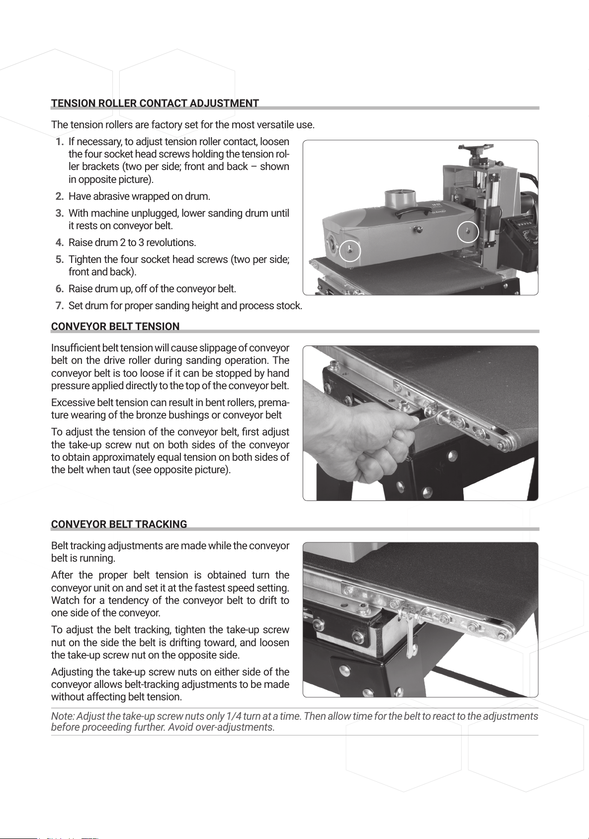
TENSION ROLLER CONTACT ADJUSTMENT
The tension rollers are factory set for the most versatile use.
1. If necessary, to adjust tension roller contact, loosen
the four socket head screws holding the tension rol-
ler brackets (two per side; front and back – shown
in opposite picture).
2. Have abrasive wrapped on drum.
3. With machine unplugged, lower sanding drum until
it rests on conveyor belt.
4. Raise drum 2 to 3 revolutions.
5. Tighten the four socket head screws (two per side;
front and back).
6. Raise drum up, off of the conveyor belt.
7. Set drum for proper sanding height and process stock.
CONVEYOR BELT TENSION
Insufcient belt tension will cause slippage of conveyor
belt on the drive roller during sanding operation. The
conveyor belt is too loose if it can be stopped by hand
pressure applied directly to the top of the conveyor belt.
Excessive belt tension can result in bent rollers, prema-
ture wearing of the bronze bushings or conveyor belt
To adjust the tension of the conveyor belt, rst adjust
the take-up screw nut on both sides of the conveyor
to obtain approximately equal tension on both sides of
the belt when taut (see opposite picture).
CONVEYOR BELT TRACKING
Belt tracking adjustments are made while the conveyor
belt is running.
After the proper belt tension is obtained turn the
conveyor unit on and set it at the fastest speed setting.
Watch for a tendency of the conveyor belt to drift to
one side of the conveyor.
To adjust the belt tracking, tighten the take-up screw
nut on the side the belt is drifting toward, and loosen
the take-up screw nut on the opposite side.
Adjusting the take-up screw nuts on either side of the
conveyor allows belt-tracking adjustments to be made
without affecting belt tension.
Note: Adjust the take-up screw nuts only 1/4 turn at a time. Then allow time for the belt to react to the adjustments
before proceeding further. Avoid over-adjustments.
17
Page 18
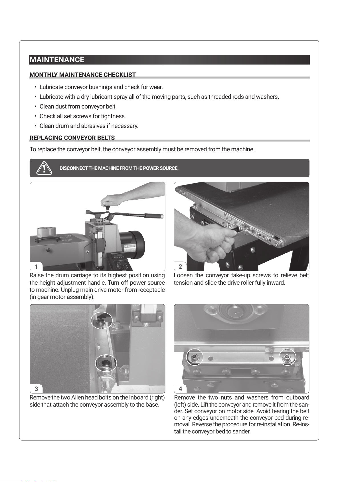
MAINTENANCE
MONTHLY MAINTENANCE CHECKLIST
• Lubricate conveyor bushings and check for wear.
• Lubricate with a dry lubricant spray all of the moving parts, such as threaded rods and washers.
• Clean dust from conveyor belt.
• Check all set screws for tightness.
• Clean drum and abrasives if necessary.
REPLACING CONVEYOR BELTS
To replace the conveyor belt, the conveyor assembly must be removed from the machine.
DISCONNECT THE MACHINE FROM THE POWER SOURCE.
Raise the drum carriage to its highest position using
the height adjustment handle. Turn off power source
to machine. Unplug main drive motor from receptacle
(in gear motor assembly).
Loosen the conveyor take-up screws to relieve belt
tension and slide the drive roller fully inward.
1 2
Remove the two Allen head bolts on the inboard (right)
side that attach the conveyor assembly to the base.
Remove the two nuts and washers from outboard
(left) side. Lift the conveyor and remove it from the san-
der. Set conveyor on motor side. Avoid tearing the belt
on any edges underneath the conveyor bed during re-
moval. Reverse the procedure for re-installation. Re-ins-
tall the conveyor bed to sander.
3 4
18
Page 19
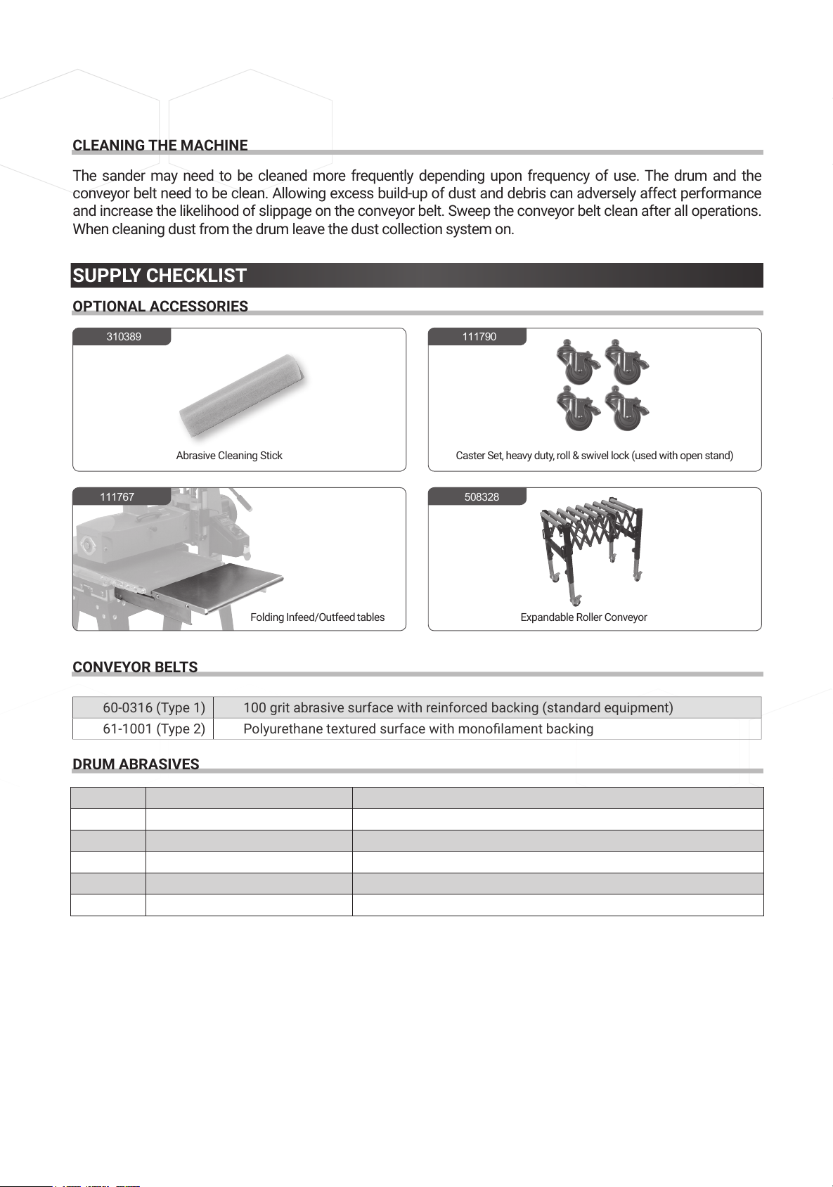
CLEANING THE MACHINE
The sander may need to be cleaned more frequently depending upon frequency of use. The drum and the
conveyor belt need to be clean. Allowing excess build-up of dust and debris can adversely affect performance
and increase the likelihood of slippage on the conveyor belt. Sweep the conveyor belt clean after all operations.
When cleaning dust from the drum leave the dust collection system on.
SUPPLY CHECKLIST
OPTIONAL ACCESSORIES
CONVEYOR BELTS
60-0316 (Type 1) 100 grit abrasive surface with reinforced backing (standard equipment)
61-1001 (Type 2)
DRUM ABRASIVES
60-6036 SuperMax Tools 16-32 - 4-Wraps in Box
60-6060 SuperMax Tools 16-32 - 4-Wraps in Box
60-6080 SuperMax Tools 16-32 - 4-Wraps in Box
60-6100 SuperMax Tools 16-32 - 4-Wraps in Box
60-6120 SuperMax Tools 16-32 - 4-Wraps in Box
60-6150 SuperMax Tools 16-32 - 4-Wraps in Box
60-6180 SuperMax Tools 16-32 - 4-Wraps in Box
60-6220 SuperMax Tools 16-32 - 4-Wraps in Box
60-6000 Assorted box (36/80/80/120 grit)
310389 111790
508328111767
Abrasive Cleaning Stick
Caster Set, heavy duty, roll & swivel lock (used with open stand)
N.B. The codes shown here are for ordering at Axminster tools
For more details visit axminstertools.com
111803 SUPMX-60-6000 16/32, 4 WRAPS PRE-CUT 36/80/80/120
111803 SUPMX-60-6036 16/32, 36G- 4 Wraps Pre-Cut
111804 SUPMX-60-6080 16/32, 80G- 4 WRAPS PRE-CUT
111805 SUPMX-60-6120 16/32, 120G- 4 WRAPS PRE-CUT
111806 SUPMX-60-6150 16/32, 150G- 4 Wraps PRE-CUT
111807 SUPMX-60-6180 16/32, 180G- 4 WRAPS PRE-CUT
N.B. The codes shown here are for ordering at Axminster tools
For more details visit axminstertools.com
19
Page 20
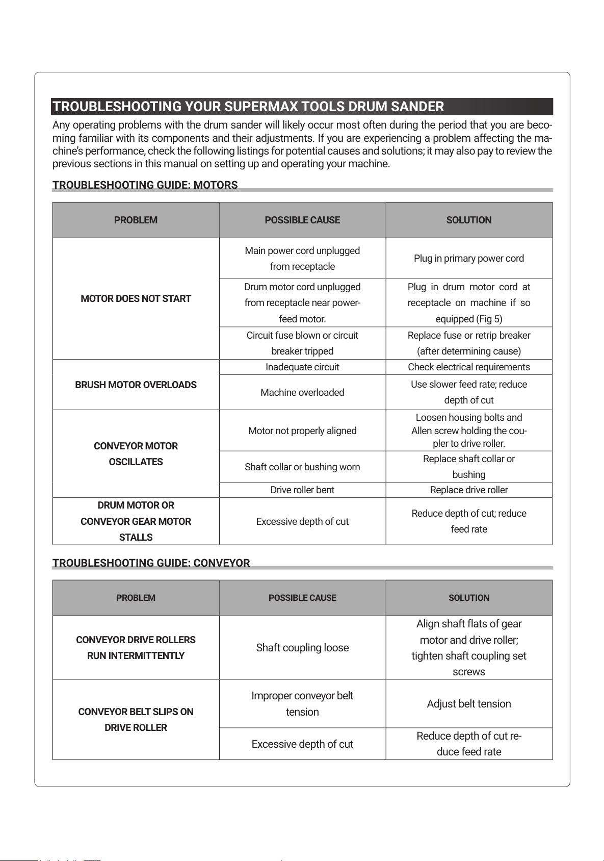
TROUBLESHOOTING YOUR SUPERMAX TOOLS DRUM SANDER
Any operating problems with the drum sander will likely occur most often during the period that you are beco-
ming familiar with its components and their adjustments. If you are experiencing a problem affecting the ma-
chine’s performance, check the following listings for potential causes and solutions; it may also pay to review the
previous sections in this manual on setting up and operating your machine.
TROUBLESHOOTING GUIDE: MOTORS
PROBLEM POSSIBLE CAUSE SOLUTION
MOTOR DOES NOT START
Main power cord unplugged
from receptacle
Plug in primary power cord
Drum motor cord unplugged
from receptacle near power-
feed motor.
Plug in drum motor cord at
receptacle on machine if so
equipped (Fig 5)
Circuit fuse blown or circuit
breaker tripped
Replace fuse or retrip breaker
(after determining cause)
BRUSH MOTOR OVERLOADS
Inadequate circuit Check electrical requirements
Machine overloaded
Use slower feed rate; reduce
depth of cut
CONVEYOR MOTOR
OSCILLATES
Motor not properly aligned
Loosen housing bolts and
Allen screw holding the cou-
pler to drive roller.
Shaft collar or bushing worn
Replace shaft collar or
bushing
Drive roller bent Replace drive roller
DRUM MOTOR OR
CONVEYOR GEAR MOTOR
STALLS
Excessive depth of cut
Reduce depth of cut; reduce
feed rate
TROUBLESHOOTING GUIDE: CONVEYOR
PROBLEM POSSIBLE CAUSE SOLUTION
CONVEYOR DRIVE ROLLERS
RUN INTERMITTENTLY
Shaft coupling loose
Align shaft flats of gear
motor and drive roller;
tighten shaft coupling set
screws
CONVEYOR BELT SLIPS ON
DRIVE ROLLER
Improper conveyor belt
tension
Adjust belt tension
Excessive depth of cut
Reduce depth of cut re-
duce feed rate
20
Page 21
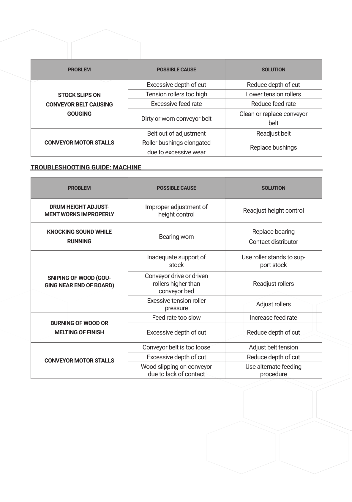
PROBLEM POSSIBLE CAUSE SOLUTION
STOCK SLIPS ON
CONVEYOR BELT CAUSING
GOUGING
Excessive depth of cut Reduce depth of cut
Tension rollers too high Lower tension rollers
Excessive feed rate Reduce feed rate
Dirty or worn conveyor belt
Clean or replace conveyor
belt
CONVEYOR MOTOR STALLS
Belt out of adjustment Readjust belt
Roller bushings elongated
due to excessive wear
Replace bushings
TROUBLESHOOTING GUIDE: MACHINE
PROBLEM POSSIBLE CAUSE SOLUTION
DRUM HEIGHT ADJUST-
MENT WORKS IMPROPERLY
Improper adjustment of
height control
Readjust height control
KNOCKING SOUND WHILE
RUNNING
Bearing worn
Replace bearing
Contact distributor
SNIPING OF WOOD (GOU-
GING NEAR END OF BOARD)
Inadequate support of
stock
Use roller stands to sup-
port stock
Conveyor drive or driven
rollers higher than
conveyor bed
Readjust rollers
Exessive tension roller
pressure
Adjust rollers
BURNING OF WOOD OR
MELTING OF FINISH
Feed rate too slow Increase feed rate
Excessive depth of cut Reduce depth of cut
CONVEYOR MOTOR STALLS
Conveyor belt is too loose Adjust belt tension
Excessive depth of cut Reduce depth of cut
Wood slipping on conveyor
due to lack of contact
Use alternate feeding
procedure
21
Page 22
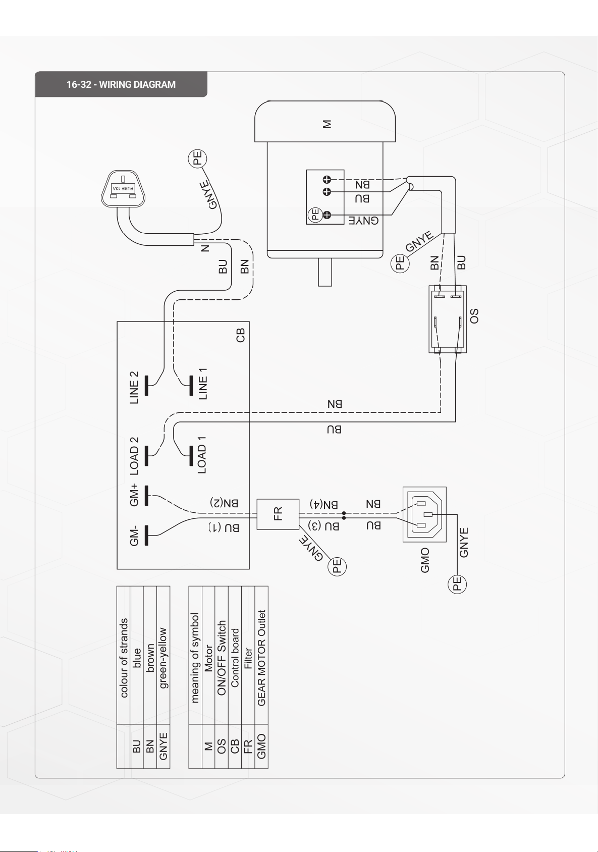
16-32 - WIRING DIAGRAM
22
Page 23
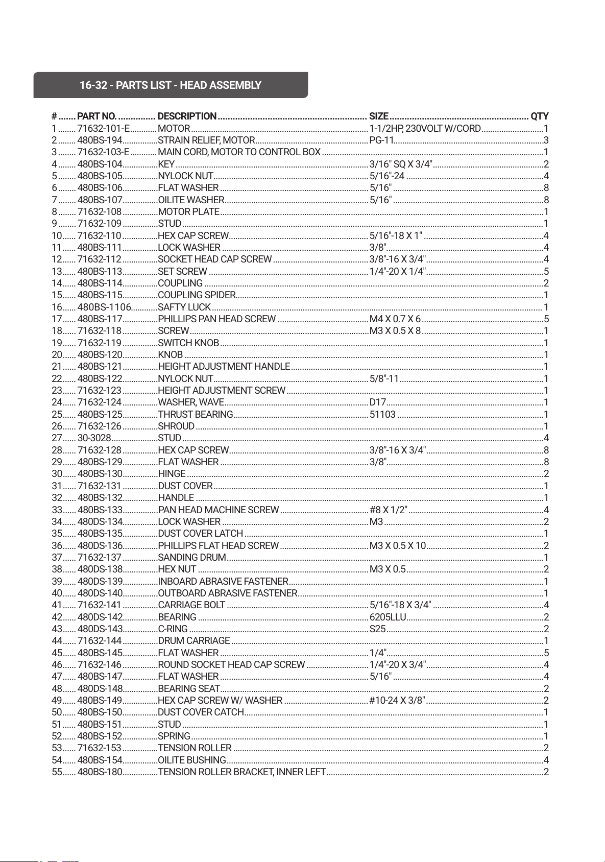
# ....... PART NO. ............... DESCRIPTION ............................................................ SIZE ........................................................ QTY
1 ........ 71632-101 - E ............MOTOR ................................................................................1-1/2H P, 230VO LT W/CORD ............................1
2 ........ 480BS-194 ................STRAIN RELIEF, MOTOR ...................................................PG-11 ....................................................................3
3 ........ 71632-103-E ............ MAIN CORD, MOTOR TO CONTROL BOX ....................................................................................................1
4 ........ 480BS-104 ................KEY .......................................................................................3/16" SQ X 3/4" ..................................................2
5 ........ 480BS-105 ................NYLOCK NUT ...................................................................... 5/16"-24 ..............................................................4
6 ........480BS-106 ................FLAT WASHER ...................................................................5/16" ....................................................................8
7 ........ 480BS-107 ................OILITE WASHER .................................................................5/16" ....................................................................8
8 ........ 71632-108 ................MOTOR PLATE ..................................................................................................................................................1
9 ........ 71632-109 ................STUD ...................................................................................................................................................................1
10 ...... 71632-110 ................HEX CAP SCREW ...............................................................5/16"-18 X 1" ......................................................4
11 ...... 480BS-111 ................LOCK WASHER ..................................................................3/8".......................................................................4
12 ...... 71632-112 ................SOCKET HEAD CAP SCREW ...........................................3/8"-16 X 3/4" .....................................................4
13 ...... 480BS-113 ................SET SCREW ........................................................................1/4"-20 X 1/4" .....................................................5
14 ...... 480BS-114 ................COUPLING .........................................................................................................................................................2
15 ...... 480BS-115 ................COUPLING SPIDER ...........................................................................................................................................1
16 ...... 480BS-1106 ............SAFTY LUCK ..................................................................................................................................................... 1
17 ...... 480BS-117 ................PHILLIPS PAN HEAD SCREW .........................................M4 X 0.7 X 6 .......................................................5
18 ...... 71632-118 ................SCREW.................................................................................M3 X 0.5 X 8 .......................................................1
19 ...... 71632-119 ................SWITCH KNOB ..................................................................................................................................................1
20 ...... 480BS-120 ................KNOB ..................................................................................................................................................................1
21 ...... 480BS-121 ................HEIGHT ADJUSTMENT HANDLE .................................................................................................................
.1
22 ...... 480BS-122 ................NYLOCK NUT ...................................................................... 5/8"-11 .................................................................1
23 ...... 71632-123 ................HEIGHT ADJUSTMENT SCREW ....................................................................................................................1
24 ...... 71632-124 ................WASHER, WAVE .................................................................D17 .......................................................................1
25 ...... 480BS-125 ................THRUST BEARING .............................................................51103 ..................................................................1
26 ......71632-126 ................SHROUD .............................................................................................................................................................1
27 ...... 30-3028 .....................STUD ...................................................................................................................................................................4
28 ...... 71632-128 ................HEX CAP SCREW ...............................................................3/8"-16 X 3/4" .....................................................8
29 ...... 480BS-129 ................FLAT WASHER ...................................................................3/8".......................................................................8
30 ...... 480BS-130 ................HINGE .................................................................................................................................................................2
31 ...... 71632-131 ................DUST COVER .....................................................................................................................................................1
32 ...... 480BS-132 ................HANDLE .............................................................................................................................................................1
33 ...... 480BS-133 ................PAN HEAD MACHINE SCREW ........................................#8 X 1/2" .............................................................4
34 ...... 480DS-134................LOCK WASHER .................................................................. M3 ........................................................................2
35 ...... 480BS-135 ................DUST COVER LATCH .......................................................................................................................................1
36 ......480DS-136................PHILLIPS FLAT HEAD SCREW ........................................M3 X 0.5 X 10 .....................................................2
37 ...... 71632-137 ................SANDING DRUM ...............................................................................................................................................1
38 ...... 480DS-138................HEX NUT .............................................................................M3 X 0.5 ..............................................................2
39 ...... 480DS-139................INBOARD ABRASIVE FASTENER ...................................................................................................................1
40 ...... 480DS-140................OUTBOARD ABRASIVE FASTENER ...............................................................................................................1
41 ...... 71632-141 ................CARRIAGE BOLT ................................................................ 5/16"-18 X 3/4" ..................................................4
42 ...... 480DS-142................BEARING .............................................................................6205LLU ..............................................................2
43 ...... 480DS-143................C-RING .................................................................................S25 .......................................................................2
44 ...... 71632-144 ................DRUM CARRIAGE .............................................................................................................................................1
45 ...... 480BS-145 ................FLAT WASHER ...................................................................1/4".......................................................................5
46 .....
.71632-146 ................ROUND SOCKET HEAD CAP SCREW ............................ 1/4"-20 X 3/4" .....................................................4
47 ...... 480BS-147 ................FLAT WASHER ...................................................................5/16" ....................................................................4
48 ...... 480DS-148................BEARING SEAT ..................................................................................................................................................2
49 ...... 480BS-149 ................HEX CAP SCREW W/ WASHER ......................................#10-24 X 3/8" .....................................................2
50 ...... 480BS-150 ................DUST COVER CATCH .......................................................................................................................................1
51 ...... 480BS-151 ................STUD ...................................................................................................................................................................1
52 ...... 480BS-152 ................SPRING ...............................................................................................................................................................1
53 ...... 71632-153 ................TENSION ROLLER ............................................................................................................................................2
54 ...... 480BS-154 ................OILITE BUSHING ...............................................................................................................................................4
55 ...... 480BS-180 ................TENSION ROLLER BRACKE T, INNER LEFT ..................................................................................................2
16-32 - PARTS LIST - HEAD ASSEMBLY
23
Page 24
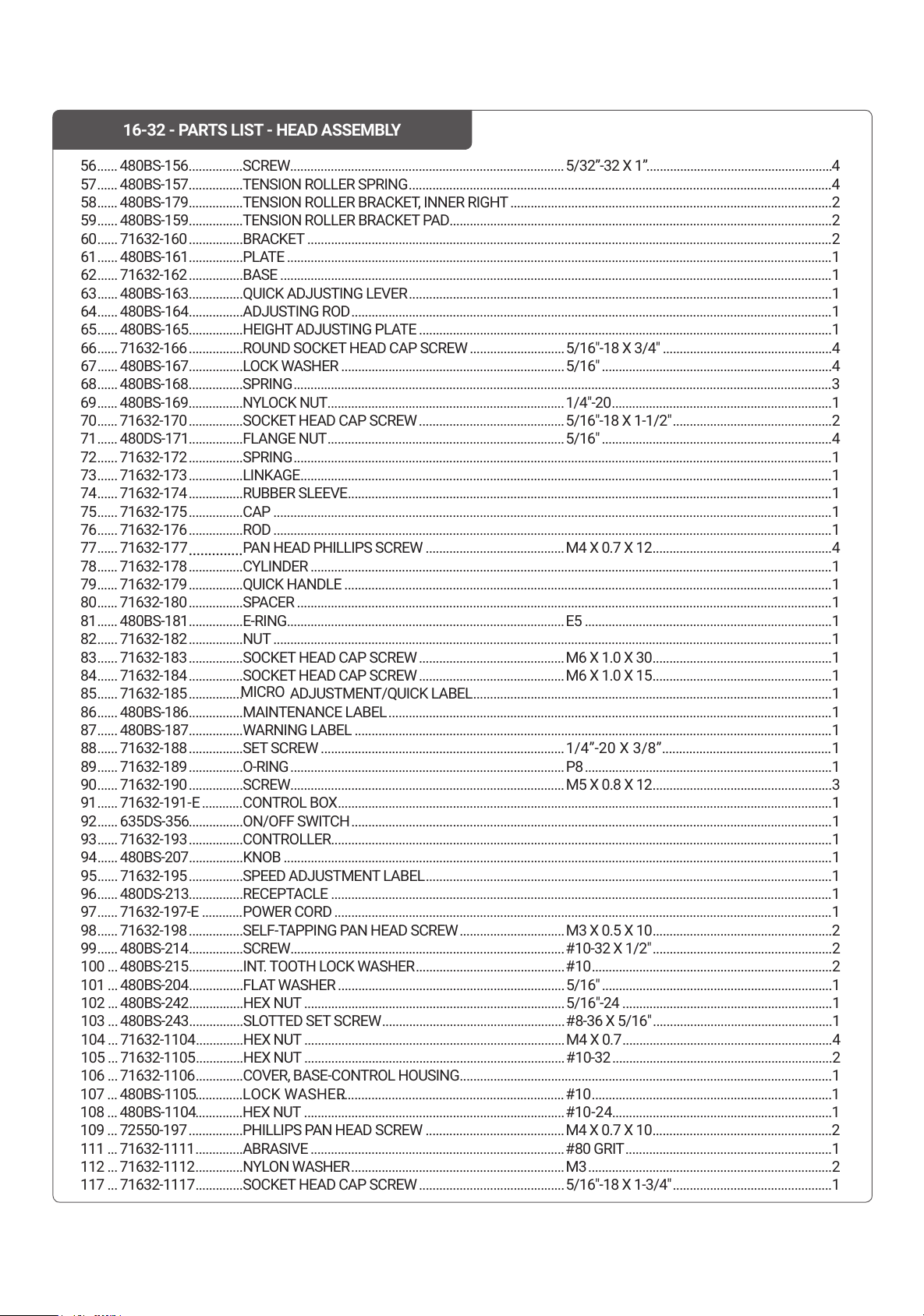
56 ...... 480BS-156 ................SCREW .................................................................................5/32”-32 X 1” .......................................................4
57 ...... 480BS-157 ................TENSION ROLLER SPRING .............................................................................................................................4
58 ...... 480BS-179 ................TENSION ROLLER BRACKE T, INNER RIGHT ...............................................................................................2
59 ...... 480BS-159 ................TENSION ROLLER BRACKET PAD .................................................................................................................2
60 ......71632-160 ................BRACKET ...........................................................................................................................................................2
61 ......480BS-161 ................PLATE .................................................................................................................................................................1
62 ......71632-162 ................BASE ...................................................................................................................................................................1
63 ......480BS-163 ................QUICK ADJUSTING LEVER .............................................................................................................................1
64 ......480BS-164 ................ADJUSTING ROD ..............................................................................................................................................1
65 ......480BS-165 ................HEIGHT ADJUSTING PLATE ..........................................................................................................................1
66 ...... 71632-166 ................ROUND SOCKET HEAD CAP SCREW ............................ 5/16"-18 X 3/4" ..................................................4
67 ......480BS-167 ................LOCK WASHER ..................................................................5/16" ....................................................................4
68 ......480BS-168 ................SPRING ...............................................................................................................................................................3
69 ......480BS-169 ................NYLOCK NUT ......................................................................1/4"-20 .................................................................1
70 ...... 71632-170 ................SOCKET HEAD CAP SCREW ...........................................5/16"-18 X 1-1/2" ...............................................2
71 ...... 480DS-171................FLANGE NUT ......................................................................5/16" ....................................................................4
72 ...... 71632-172 ................SPRING ...............................................................................................................................................................1
73 ...... 71632-173 ................LINKAGE .............................................................................................................................................................1
74 ...... 71632-174 ................RUBBER SLEEVE ...............................................................................................................................................1
75 ...... 71632-175 ................CAP .....................................................................................................................................................................1
76 ......71632-176 ................ROD .....................................................................................................................................................................1
77 ...... 71632-177
..............
PAN H EAD PHILLIPS SCREW .........................................M4 X 0.7 X 12 .....................................................4
78 ...... 71632-178 ................CYLINDER ..........................................................................................................................................................1
79 ...... 71632-179 ................QUICK HAND
LE ................................................................................................................................................1
80 ...... 71632-180 ................SPACER ..............................................................................................................................................................1
81 ...... 480BS-181 ................E-RING ..................................................................................E5 .........................................................................1
82 ...... 71632-182 ................NUT .....................................................................................................................................................................1
83 ...... 71632-183 ................SOCKET HEAD CAP SCREW ...........................................M6 X 1.0 X 30 .....................................................1
84 ...... 71632-184 ................SOCKET HEAD CAP SCREW ........................................... M6 X 1.0 X 15 .....................................................1
85 ...... 71632-185 ................
MICRO
ADJUSTMENT/QUICK LABEL ..........................................................................................................1
86 ......480BS-186 ................MAINTENANCE LABEL ...................................................................................................................................1
87 ...... 480BS-187 ................WARNING LABEL .............................................................................................................................................1
88 ...... 71632-188 ................SET SCREW ........................................................................1/4”-20 X 3/8” ..................................................1
89 ...... 71632-189 ................O-RING ................................................................................. P8 .........................................................................1
90 ...... 71632-190 ................SCREW .................................................................................M5 X 0.8 X 12 .....................................................3
91 ...... 71632-191 - E ............CONTROL BOX ..................................................................................................................................................1
92 ...... 635DS-356 ................ON/OFF SWITCH ..............................................................................................................................................1
93 ...... 71632-193 CONTROLLER ....................................................................................................................................................1
94 ...... 480BS-207 ................KNOB ..................................................................................................................................................................1
95 ...... 71632-195 ................SPEED ADJUSTMENT LABEL ........................................................................................................................1
96 ......480DS-213................RECEPTACLE ....................................................................................................................................................1
97 ...... 71632-197-E POWER CORD ...................................................................................................................................................1
98 ...... 71632-198 ................SELF-TAPPING PAN HEAD SCREW ...............................M3 X 0.5 X 10 .....................................................2
99 ...... 480BS-214 ................SCREW .................................................................................#10-32 X 1/2" .....................................................2
100 ...480BS-215 ................INT. TOOTH LOCK WASHER ............................................#10 .......................................................................2
101 ...480BS-204 ................FLAT WASHER ...................................................................5/16" ....................................................................1
102 ...480BS-242 ................HEX NUT .............................................................................5/16"-24 ..............................................................1
103 ...480BS-243 ................SLOTTED SE
T SCREW ......................................................#8-36 X 5/16" .....................................................1
104 ...71632-1104 ..............HEX NUT .............................................................................M4 X 0.7 ..............................................................4
105 ...71632-1105 ..............HEX NUT .............................................................................#10-32 .................................................................2
106 ...71632-1106 ..............COVER, BASE-CONTROL HOUSING ..............................................................................................................1
107 ...480BS-1105 ..............LOCK WASHER ................................................................... 1
108 ...480BS-1104 ..............HEX NUT 1
109 ...72550-197 ................PHILLIPS PAN HEAD SCREW .........................................M4 X 0.7 X 10 .....................................................2
111 ...71632-1111 ..............ABRASI V E
112 ... 71632-1112 ..............NYLON WASHER
...........................................................................#80 GRIT .............................................................1
117 ...71632-1117 ..............
...............................................................M3 ........................................................................2
16-32 - PARTS LIST - HEAD ASSEMBLY
............
#10.......................................................................
.............................................................................#10-24.................................................................
...........................................SOCKET HEAD CAP SCREW 5/16"-18 X 1-3/4"...............................................1
................
24
Page 25

16-32 - PARTS LIST - HEAD ASSEMBLY
121 ...71632-1121 .............. 1
122 ...71632-1122 ..............TOOL STORAGE ...............................................................................................................................................1
123 ...71632-1123 ..............DRO FIXED PLATE ...........................................................................................................................................1
124 ...71632-1124 ..............DIGITAL READOUT ASSEMBLY ....................................................................................................................1
FL AT WASHER ...................................................................M3 ........................................................................
25
Page 26
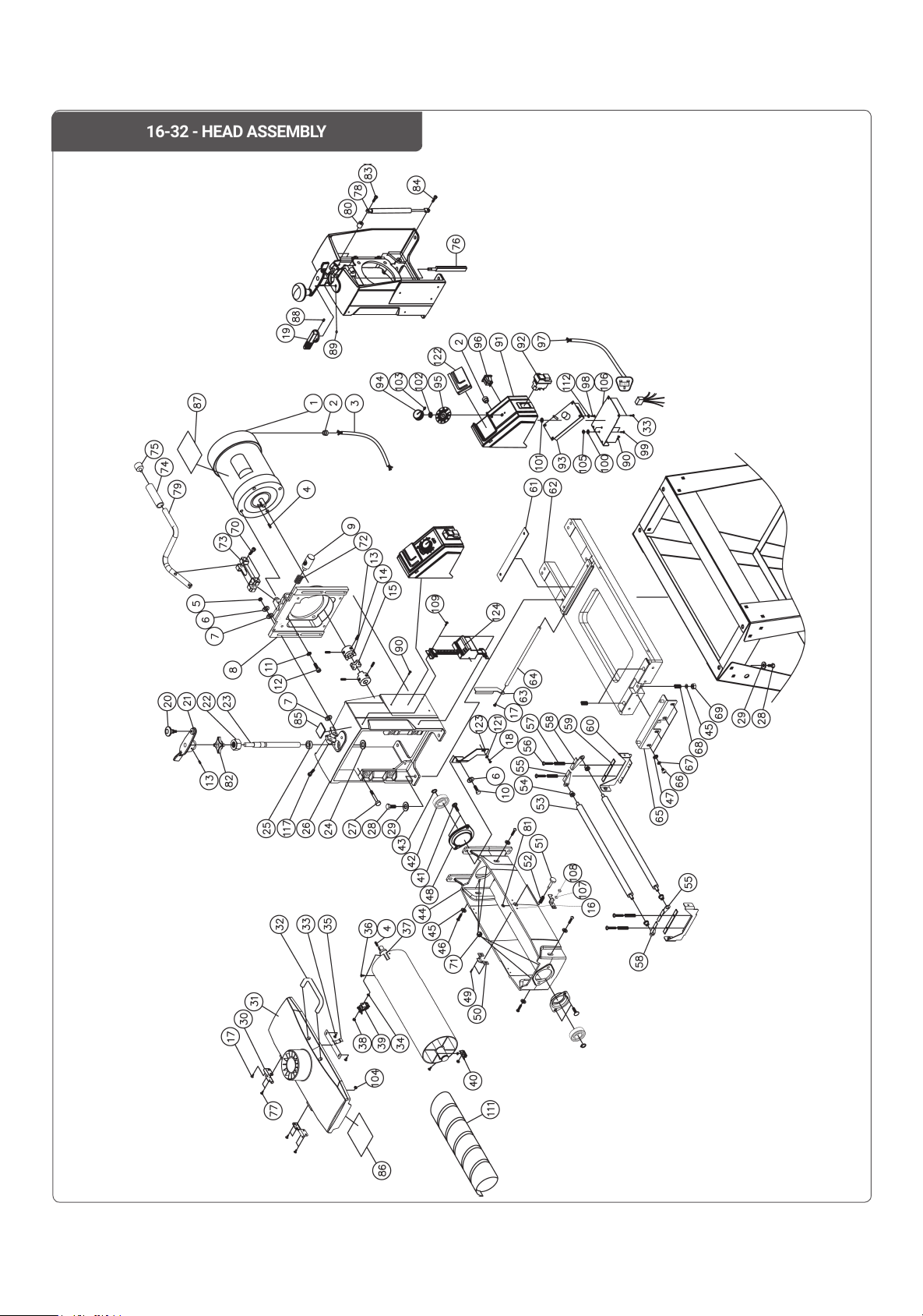
16-32 - HEAD ASSEMBLY
26
Page 27
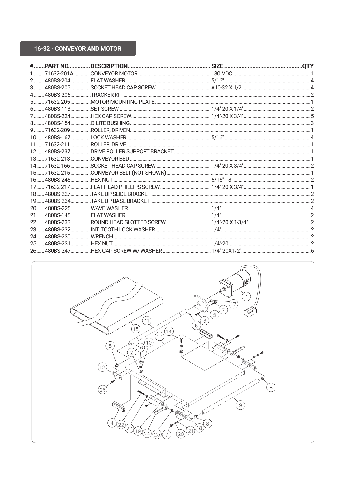
# .......PART NO. .............DESCRIPTION..................................................... SIZE ..................................................QTY
1 ........ 71632-201 A .............CONVEYOR MOTOR .........................................................180 V D C ..............................................................1
2 ........ 480BS-204 ................FLAT WASHER ...................................................................5/16" ....................................................................4
3 ........ 480BS-205 ................SOCKET HEAD CAP SCREW ...........................................#10-32 X 1/2" .....................................................4
4 ........ 480BS-206 ................TRACKER KIT ....................................................................................................................................................2
5 ........ 71632-205 ................MOTOR MOUNTING PLATE ...........................................................................................................................1
6 ........480BS-113 ................SET SCREW ........................................................................1/4"-20 X 1/4" .....................................................2
7 ........ 480BS-224 ................HEX CAP SCREW ............................................................... 1/4"-20 X 3/4" .....................................................5
8 ........ 480BS-154 ................OILITE BUSHING ...............................................................................................................................................3
9 ........ 71632-209 ................ROLLER, DRIVEN ...............................................................................................................................................1
10 ...... 480BS-167 ................LOCK WASHER ..................................................................5/16" ....................................................................4
11 ...... 71632-211 ................ROLLER, DRIVE ..................................................................................................................................................1
12 ...... 480BS-237 ................DRIVE ROLLER SUPPORT BRACKET ............................................................................................................1
13 ...... 71632-213 ................CONVEYOR BED ...............................................................................................................................................1
14 ...... 71632-166 ................SOCKET HEAD CAP SCREW ...........................................1/4"-20 X 3/4" .....................................................2
15 ...... 71632-215 ................CONVEYOR BELT (NOT SHOWN) ..................................................................................................................1
16 ......480BS-245 ................HEX NUT .............................................................................5/16"-18 ..............................................................2
17 ...... 71632-217 ................FLAT HEAD PHILLIPS SCREW ........................................ 1/4"-20 X 3/4" .....................................................1
18 ...... 480BS-227 ................TAKE UP SLIDE BRACKET ..............................................................................................................................2
19 ...... 480BS-234 ................TAKE UP BASE BRACKET ...............................................................................................................................2
20 ...... 480BS-225 ................WAVE WASHER .................................................................1/4".......................................................................4
21 .....
. 480BS-145 ................FLAT WASHER ...................................................................1/4".......................................................................2
22 ...... 480BS-233 ................ROUND HEAD SLOTTED SCREW ..................................1/4"-20 X 1-3/4" .................................................2
23 ...... 480BS-232 ................INT. TOOTH LOCK WASHER ............................................1/4".......................................................................2
24 ...... 480BS-230 ................WRENCH ............................................................................................................................................................2
25 ...... 480BS-231 ................HEX NUT .............................................................................1/4"-20 .................................................................2
26 ......480BS-247 ................HEX CAP SCREW W/ WASHER ......................................1/4"-20X1/2" .......................................................6
16-32 - CONVEYOR AND MOTOR
27
Page 28
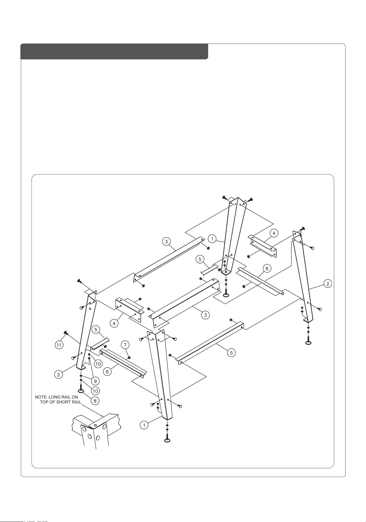
16-32 - OPEN STAND ASSEMBLY
# .......PART NO. .............DESCRIPTION..................................................... SIZE ..................................................QTY
1 .......480BS-501 ........... LEG, LEFT ..........................................................................................................................................2
2 .......480BS-502 ........... LEG, RIGHT (WITH TOOL HOLDER) ..............................................................................................2
3 .......71632-303 ............ TOP CROSS BRACE, LONG ............................................................................................................2
4 .......71632-304 ............ TOP CROSS BRACE, SHORT ..........................................................................................................2
5 .......71632-305 ............ LOWER CROSS BRACE RAIL, LONG .............................................................................................2
6 ....... 71632-306 ............LOWER CROSS BRACE RAIL, SHORT ..........................................................................................2
7 .......480BS-507 ........... FLANGE NUT ............................................................. 5/16" ..........................................................
8 .......480BS-508 ........... LEVELING FOOT ..............................................................................................................................4
9 .......480BS-129 ........... FL AT WASHER ..........................................................3/8" ..............................................................8
10..... 480BS-509 ........... HEX NUT..................................................................... 3/8"-16 .........................................................8
11..... 480BS-506 ........... CARRIAGE BOLT .......................................................5/16"-18 X 5/8" ........................................ 24
24
28
Page 29

Laguna Tools Inc.
UK DECLARATION OF CONFORMITY
‘original’
Product model: 16-32 Drum Sander
Name and address of the manufacturer: Laguna Tools Inc. 2072 Alton Parkway, Irvine, California
92606, USA.
Name and address of the UK Authorised Representative: Axminster Tool Centre Ltd, Unit 10 Weycroft
Avenue, Axminster, Devon EX13 5PH, United Kingdom.
This declaration of conformity is issued under the sole responsibility of the manufacturer.
Object of the declaration: 16-32 Drum Sander
The object of the declaration described above is in conformity with the relevant GB legislation:
Supply of Machinery (Safety) Regulations 2008 as amended.
Electromagnetic Compatibility Regulations 2016 as amended.
References to the relevant harmonised standards used or references to the other technical
specifications in relation to which conformity is declared:
.
EN ISO 12100:2010 Safety of machinery - General principles for design - Risk assessment and risk reduction.
EN 60204-1:2018 Safety of machinery - Electrical equipment of machines - Part 1: General requirements.
ISO 13849-1:2023 Safety of machinery - Safety-related parts of control systems - Part 1: General principles for
design (ISO 13849-1:2023).
EN 50370-1:2005 Electromagnetic compatibility (EMC) - Product family standard for machine tools - Part 1:
Emission.
EN 50370-2:2003 Electromagnetic compatibility (EMC) - Product family standard for machine tools - Part 2:
Immunity.
EN 61000-4-2:2009 Electromagnetic compatibility (EMC) -Part 4-2: Testing and measurement techniques Electrostatic discharge immunity test.
EN 61000-4-4:2012 Electromagnetic compatibility (EMC) - Part 4-4: Testing and measurement techniques - Electrical
fast transient/burst immunity test (IEC 61000-4-4:2012). IEC 61000-4-6:2023 Electromagnetic compatibility (EMC) Part 4-6: Testing and measurement techniques - Immunity to conducted disturbances, induced by radio-frequency
fields.
EN IEC 61000-6-4:2019 Electromagnetic compatibility (EMC) - Part 4-6: Testing and measurement techniques Immunity to conducted disturbances, induced by radio-frequency fields.
Additional information:
Name and address of person authorised to compile the technical file: Axminster Tool Centre
Ltd, Unit 10 Weycroft Avenue, Axminster, Devon EX13 5PH, United Kingdom
The machinery fulfils all relevant provisions of Supply of Machinery (Safety) Regulations 2008
as amended.
Signed for and behalf of: Axminster Tool Centre Ltd.
(place and date of issue): Axminster, Devon, United Kingdom, 20
(name, function): Andrew Parkhouse, Supply Chain Director
Signature:
29
th
June 2024
Page 30

30
Page 31

Warranty
New machines and accessories sold by Laguna Tools carry a one-year
warranty effective from the date of shipping.
Laguna Tools guarantees all new machines and accessories sold to be
free of manufacturers’ defective workmanship, parts and materials.
We will repair or replace, without charge, any parts determined by
Laguna Tools, Inc. to be a manufacturer’s defect.
We require that the defective item/part be returned to the Laguna
appointed dealer you purchased from with the complaint. Photographic / videos maybe required when any fault is reported so we can
agree action needed. Any machines returned to Laguna appointed dealer must be returned with packaging in the same manner
in which it was received. If a part or blade is being returned it must
have adequate packaging to ensure no damage is received during
shipping. In the event the item/part is determined to be damaged
due to lack of maintenance, cleaning or misuse/abuse, the customer
will be responsible for the cost to replace the item/part, plus all related shipping charges. This limited warranty does not apply to natural
disasters, acts of terrorism, normal wear and tear, product failure due
to lack of maintenance or cleaning, damage caused by accident,
neglect, lack of or inadequate dust collection, misuse/abuse or damage caused where repair or alterations have been made or attempted
by others. Laguna Tools, Inc. is not responsible for additional tools or
modifications sold or per ormed (other than from/by Laguna Tools,
Inc.) on any Laguna Tools, Inc. machine.
Warranty maybe voided upon the addition of such described tools
and/or modifications, de ermined on a case-by-case basis.
Normal user alignment, adjustment, tuning, machine settings and
consumables I.E; blades are not covered by this warranty. It is the
responsibility of the user to understand basic machinery operation,
settings and procedures and to properly maintain the equipment in
accordance with the standards provided by the manufacturer.
The labour required to install replacement parts is the responsibility
of the user. Laguna Tools is not responsible for damage or loss caused
by a freight company or other circumstances not in our control.
All claims for loss or damaged goods must be notified o the authorised dealer within twenty-four hours, if the machine is received damaged it must be signed for damaged.
Only new machines sold to the original owner are covered by this
warranty.
31
Page 32

Distributed by
The packaging is suitable for recycling.
Please dispose of it in a responsible manner.
EU Countries Only
Do not dispose of electric tools together with household waste material.
By law they must be collected and recycled separately.
For after sales help visit
axminstertools.com or call 03332 406406
Axminster Tools, Axminster Devon EX13 5PH
 Loading...