

laguna 14-Twelve Bandsaw User Manual
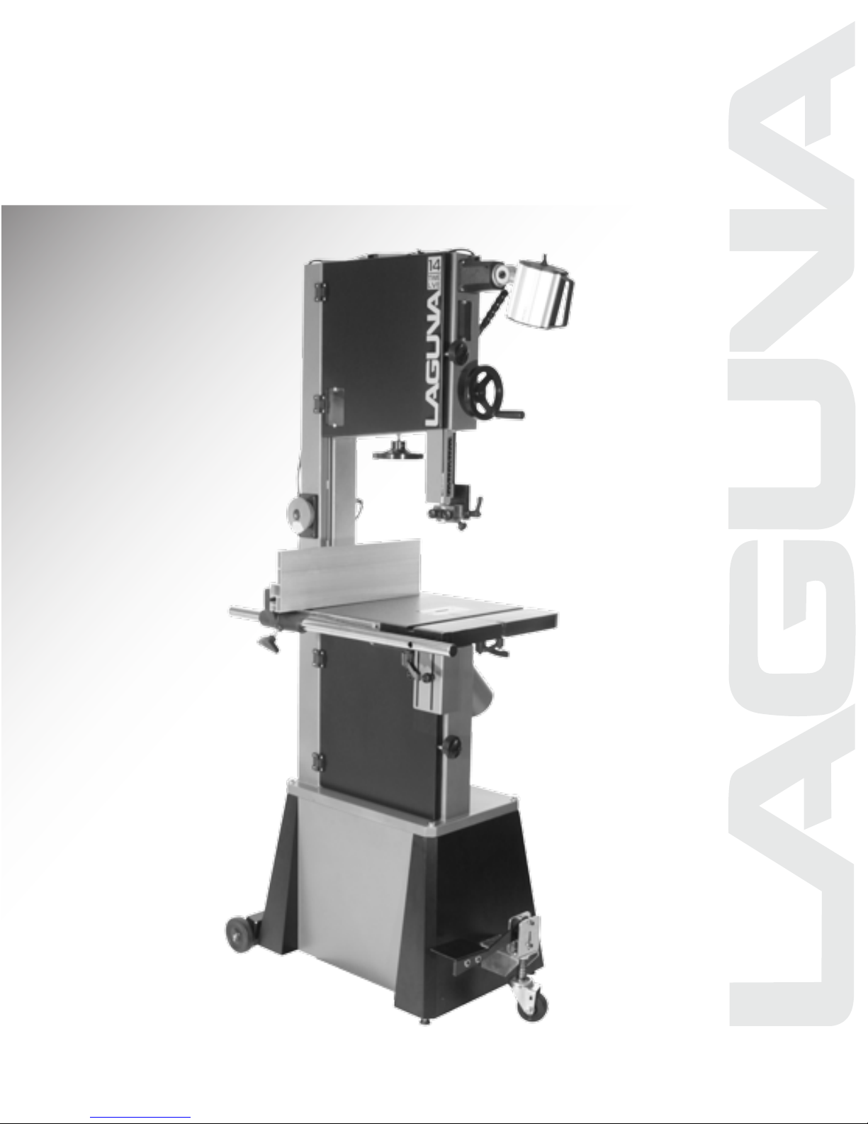
14-Twelve
Bandsaw Manual
LAGUNA TOOLS
17101 Murphy Ave.
Irvine, California 92614
Ph: 800.234.1976
www.lagunatools.com
Part No. MBAND1412-175
© 2013 Laguna Tools, Inc. All rights reserved.

2
Dear Woodworker,
Thank you for your purchase and welcome to the Laguna Tools group of
discriminating woodworkers. I understand that you have a choice of where to
purchase your machines and appreciate the confidence you have in our
products.
Every machine sold by Laguna Tools has been carefully designed and well
thought through from a woodworker’s perspective. I cut on our bandsaws,
lathes, table saws and combination machines. Through
experience, I work hard to make our machines better. I strive to give you
machines that inspire you to create works of art. Machines that are a joy to run
and work on. Machines that encourage your performance.
Today, we offer high-performance machines with innovative solutions that
meet the needs of woodworkers and their ever-evolving craft.
my hands-on
I started Laguna Tools as a woodworker; I still am.
Thank you again for beco
Torben Helshoj
President and Founder - Laguna Tools
Thriving on Innovation
ming a Laguna Tools customer.

3
WARNING: For your own safety, read instruction manual before operating bandsaw
1. Wear eye protection.
2. Do not remove jammed cut off pieces until blade has stopped.
3. Maintain proper adjustment of blade tension, blade guides and thrust
bearings.
4. Adjust upper guide to just clear workpiece.
5. Hold workpiece firmly against table.
6. ALWAYS USE A PUSH STICK. Never allow your hands / fingers to come close
to the bandsaw blade.
Safety Rules
1. KEEP GUARDS IN PLACE and in working order.
2. REMOVE ADJUSTING KEYS AND WRENCHES.
keys and adjusting wrenches are removed from tool before turning it on.
that
3. KEEP WORK AREA CLEAN. Cluttered areas and benches invite accidents.
4. DON'T USE IN DANGEROUS ENVIRONMENT. Don't use power tools in damp
or wet locations, or expose them to rain. Keep work area well lighted.
5. KEEP CHILDREN AWAY. All visitors should be kept safe distance from work
area.
6. MAKE WORKSHOP KID PROOF with padlocks, ma
starter keys.
7. DON'T FORCE TOOL. It
was designed.
8. USE RIGHT TOOL. Don't force tool or attachment to do a job for which it was not
designed.
9. USE PROPER EXTENSION CORD. Make sure your extension cord is in good
condition. When using an extension cord, be sure to use one heavy enough to
carry the current your product will draw. An undersized cord will cause
line voltage, resulting in loss of power and overheating. Table A shows the
correct size to use depending on cord length and nameplate ampere rating. If in
doubt, use the next heavier gage. The smaller the gage number, the heavier the
cord.
10. WEAR PROPER APPAREL. Do not wear loose clothing, gloves, neckties, rings,
bracelets or other jewelry that may get caught in moving parts. Nonslip footwear
is recommended. Wear protective hair c
Form habit of checking to see
ster switches or by removing
will do the job better and safer at the rate for which it
a drop in
overing to contain long hair.

4
Table A
Amperage Rating
Volts
Total length of cord in feet
120
25
50
100
150
240
50
100
200
300
More Than
Not More Than Minimum gauge for cord
0
6
18
16
16
14
6
10
18
16
14
12
10
12
16
16
14
12
12
16
14
12
Not Recommended
11. ALWAYS USE SAFETY GLASSES. Also use face or dust mask if cutting
operation is dusty. Everyday eyeglasses only have impact-resistant lenses; they
are NOT safety glasses.
12. SECURE WORK. Use clamps or a vise to hold work when practical. It's safer
than using your hand, and it frees both hands to operate tool.
13. DON'T OVERREACH. Keep proper footing and balance at all times.
14. MAINTAIN TOOLS WITH CARE. Keep tools sharp and clean for best and safest
performance. Follow instructions for lubricating
and changing accessories.
15. DISCONNE
CT TOOLS before servicing, when changing accessories such as
blades, bits and cutters.
16. REDUCE THE RISK OF UNINTENTIONAL STARTING. Make sure switch is in
off position before plugging in.
17. USE RECOMMENDED ACCESSORIES. Consult the owner's manual for
recommended accessories. The use of improper accessories may cause risk of
injury to persons.
18. NEVER STAND ON TOOL Serious injury could occur if the tool is tipped or
if the
cutting tool is unintentionally contacted.
19. CHEC
K DAMAGED PARTS. Before further use of the tool, a guard or other part
that is damaged should be carefully checked to determine that it will operate
properly and perform its intended function – check for alignment of moving parts,
binding of moving parts, breakage of parts, mounting and any other conditions
that may affect its operation. A guard or other part that is damaged sh
ould be
properly repaired or replaced.
20. DIRECTION OF FEED. Feed work into a blade or cutter against the direction of
rotation of the blade or cutter only.
21. NEVER LEAVE TOOL RUNNING UNATTENDED TURN POWER OFF. Don't
leave tool until it comes to a complete stop.

5
Grounding Instructions
1. All grounded, cord-connected tools:
In the event of a malfunction or breakdown, grounding provides a path of least
resistance for electric current to reduce the risk of electric shock. This tool is
equipped with an electric cord having an equipment-grounding conductor and a
grounding plug. The plug must be plugged into a matching outlet that is properly
installed and grounded in accordance with all local codes and ordinances.
Do no
installed by a qualified electrician.
Improper connection of the equipment-grounding conductor can result in a risk of
electric shock. The conductor with insulation having an outer surface that is
green with or without yellow stripes is the equipment-grounding conductor. If
repair or replacement of the electric cord or plug is necessary, do not connect
th
Check with a qualified electrician or service personnel if the grounding
instructions are not completely understood, or if in doubt as to whether the tool is
properly grounded.
Use only 3-wire extension cords that have 3-prong grounding plugs and 3 pole
receptacles that accept the tool's plug.
Repair or replace damaged or worn cord immediately.
2. Grounded, cord-connected tool
nominal rating less than 150 volts:
t modify the plug provided – if it
e equipment-grounding conductor to a live terminal.
This tool is intended for
illustrated in Sketch A in Fig. 1. The tool has a grounding plug that looks like the
plug illustrated in Sketch A in Fig. 1. A temporary adapter, which looks like the
adapter illustrated in Sketch B and C, may be used to connect this plug to a 2pole receptacle as show
available. The temporary adapter should be used only until a properly grounded
outlet can be installed by a qualified electrician. This adapter is not permitted
in Canada. The green-colored rigid ear, lug and the like, extending from the
adapter, must be connected to a permanent ground such as a properly
grounded outlet box.
use on a circuit that has an outlet that looks like the one
n in Sketch B if a properly grounded outlet is not
will not fit the outlet, have the proper outlet
s intended for use on a supply circuit having a

6
Fig. 1
3. Grounded, cord-connected tools intended for use on a supply circuit having a
nominal rating of 150–250 volts, inclusive:
This tool is intended for use on a circuit that has an outlet that looks like the one
illustrated in Sketch D. The tool has a grounding plug that looks like the plug
illustrated in Sketch D. Make sure the tool is connected to an outlet having the
same configuration as the plug. No adapter is available or should be used with
this tool. If the tool must be reconnected for use on a different type of electric
circuit, the reconnection should be made by qualified service personnel; and
after reconnection, the tool should comply with all local codes and ordinances.

7
Page number
Safety Rules
3
Warranty
8
Noise emission
9
Specification sheet
9
Receiving your machine
10
Introduction to your machine
10
Parts of the bandsaw
13
Where to locate your machine
17
Unpacking your machine
17
Assembly and set up
18
Testing the bandsaw
26
Using the bandsaw
36
Maintenance and troubleshooting
48
Electrical drawing
53
Exploded view drawings and parts list
54
Table of Contents

8
Limited Warranty
New woodworking machines sold by Laguna Tools carry a one-year warranty from
the date of shipping. Laguna Tools guarantees all new machines sold to be free of
manufacturers’ defective workmanship, parts, and materials.
We will repair or replace, without charge, any parts determined by Laguna Tools,
Inc., to be a manufacturer's defect. We require the defective item/part to be returned
to Laguna Tools. In the event the item/part is determined to be damaged due to lack
maintenance, cleaning or misuse/abuse, the customer will be responsible for the
of
cost to replace the item/part, plus all related shipping charges.
This limited warranty does not apply to natural disasters, acts of terrorism, normal
wear and tear, product failure due to lack of maintenance or cleaning, damage
caused by accident, neglect, lack of or inadequate dust collection, misuse/abuse or
damage caused when repair or alterations have been made or attempted by others.
Laguna Tools,
performed (other than from/by Laguna Tools, Inc.) on any Laguna Tools, Inc.,
woodworking machine. Warranty may be voided upon the addition of such noted
tools and/or modifications, determined on a case-by-case basis.
Normal user alignment, adjustment, tuning and machine settings are not covered by
this warranty. It is the responsibility of the user to understand basic woodworking
machinery settings and
accordance with the standards provided by the manufacturer.
Parts, under warranty, are shipped at Laguna Tools, Inc's cost either by common
carrier, FedEx Ground service or similar method.
Technical support to install replacement parts is primarily provided by phone, fax, or
e-mail. The labor required to install replacement parts is the responsibility of the
user.
Laguna Tools is not responsible for damage or loss ca
other circumstances not in our control.
Only new machines sold to the original owner are covered by this warranty.
For warranty repair information, call 1-800-332-4094.
Copyright 2012 Laguna Tools, Inc
** Warning – no portion of these materials may be reproduced without written
approval from Laguna Tools, Inc.
Inc., is not responsible for additional tools or modifications sold or
procedures and to properly maintain the equipment in
used by a freight company or

9
Motor voltage/hp
Breaker
15 amp
Throat
13 5/8" (346mm)
Table cast iron
16" x 21 1/2" (406.4mm x 546mm)
Table tilt
- 7 degrees + 45 degrees
Miter slot
3/8" x 3/4" (9.525mm x 19.05mm)
Table height
38" (965mm)
Fly wheel
Cast iron
Resaw Capacity
12" (305mm)
Minimum Blade length
114 3/4" (2,914mm)
Maximum blade length
116" (2,946mm)
Maximum blade width
3/4" (19mm)
Minimum blade width
1/8" (3mm)
Guides
Laguna ceramic
Height
70 1/4" (1,784mm)
Machine Dimensions (W x D)
Stand Footprint
31 1/2" x 26 7/8" (800mm x 683mm)
25 1/4" x 18 1/8" (642mm x 460mm)
Machine Dimensions with
kit
34 3/4" x 27 1/4" (882mm x 692mm)
Weight gross
275 lbs (125 kg)
Weight net
258 lbs (117 kg)
Package size
22 7/8" x 22 7/8" x 55" (581mm x
581mm x 1397mm)
Mobility kit
Optional
Industrial work-light
Optional
Noise Emission
.
Notes concerning noise emission
Given that there exists a relationship between noise level and exposure times, it is
not precise enough to determine the need for supplementary precautions. The
factors affecting the true level of exposure to operators are clearly the amount of
time exposed, the characteristics of working environment, other sources of dust and
noise, etc. For example, adjacent machines may contribute to the level of ambient
noise. It is possible that exposure level limits will vary from country to country.
.
Specification Sheet
115/230V, 1-3/4HP, 60Hz, 14/7A,
prewired 115V, 50W work lamp as option)
mobility kit (W x D)
Stand Footprint with mobility
33 3/16" x 20 1/2" (843mm x 521mm)
10
Receiving Your Machine
.
It is probable that your machine will be delivered by a third party. Before you unpack
your new machine, you will need to first inspect the packing, invoice and shipping
documents supplied by the driver.
Ensure that there is no visible damage to the packing or the machine. You need to
do this prior to the driver leaving. All damage must be noted on the delivery
documents and signed by you and the delivery driver. You must then contact the
seller within 24 hours.
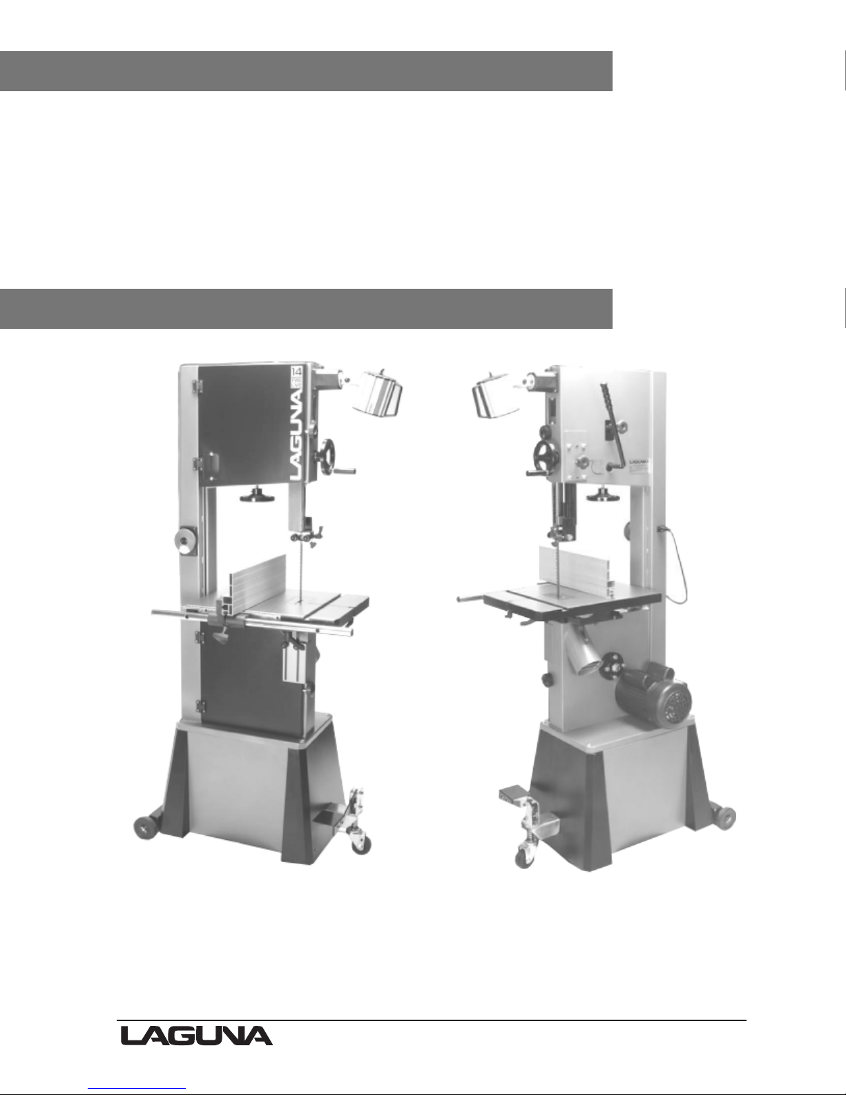
Introduction to Bandsaws
.
This bandsaw is designed to give you years of safe service. Read this owner’s
manual in its entirety before assembly or use.
The bandsaw is generally defined as a saw blade in the form of an endless steel
band that rotates around two or more wheels. This blade is a continuous metal band
with teeth on one side. As the wheels rotate, so does the band, which creates the

11
continuous sawing action. Because the direction of the blade is always downward
Optional mobility kit
Stand plates
toward the table, there is little danger (except for special cuts) that the wood will be
thrown back at the operator, which is called a kickback. There is always danger of
kickback when a circular saw is being used.
For safety reasons many woodworkers prefer the bandsaw especially when cutting
small pieces. The unique feature of the bandsaw is that the work piece can be
rotated around th
e blade creating a curve. It is the tool most often used when curves
have to be cut in wood. Because the bandsaw blade is fairly thin, it can cut thick
stock with a minimum of horsepower. For this reason the bandsaw is often used
when valuable pieces of wood are made into a thin piece of veneer.
What you will receive with the bandsaw.
Optional light
Stand side plates
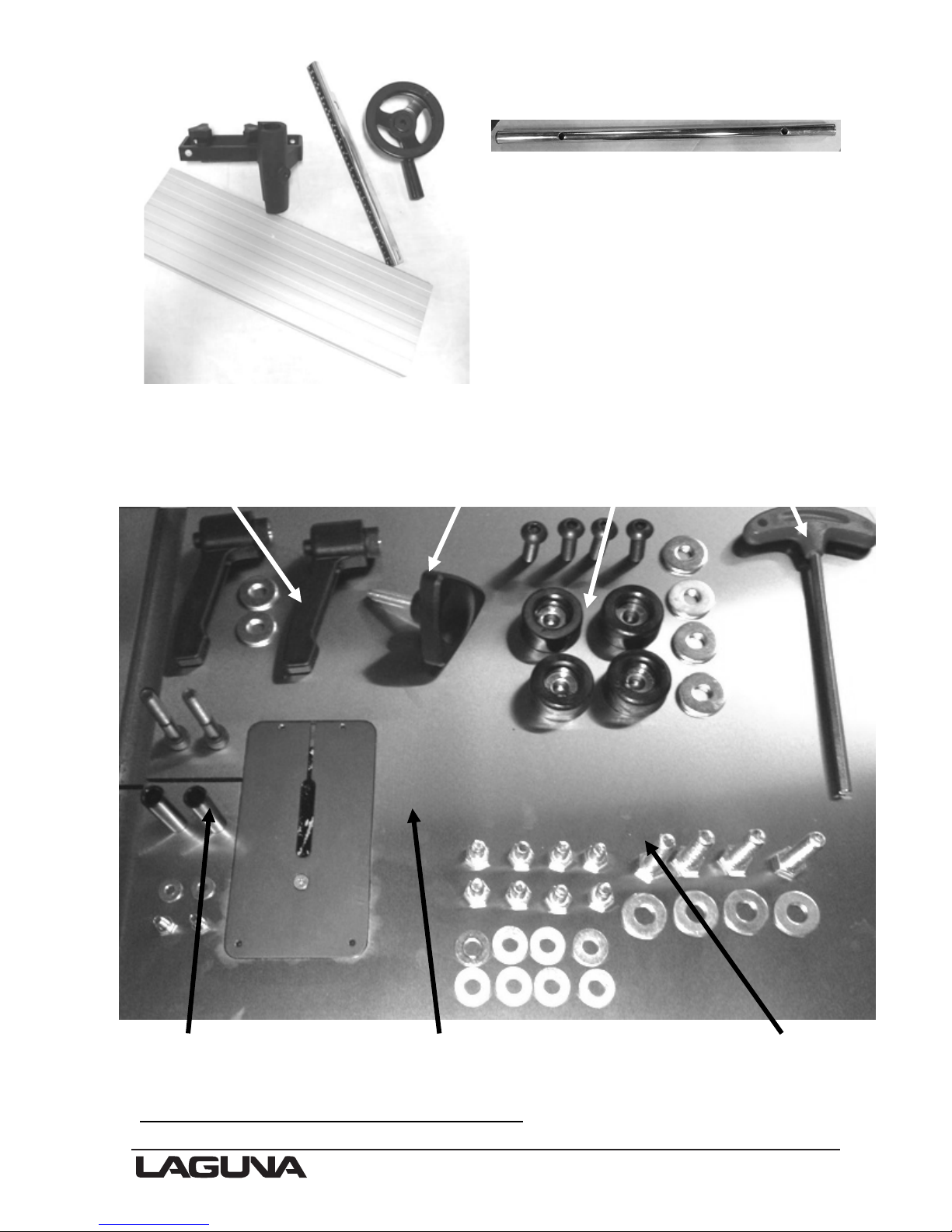
12
Fence parts and hand wheel
Fence guide bar
Table ratchet handles Fence lock knob Feet & screws T-handle
Fence bar parts and fixings Table Fixings
Note: The mobility kit and light are optional

13
2 1 5 6 8
15 16 12 13 4
9 11 3 17
1. Tension indicator window
10. Rip fence assembly
2. Switch
11. Dust port 4”
3. Motor
12. Quick-release blade tension lever
4. Frame
13. Blade tracking knob
5. Blade tension handle
14. Optional mobility kit
6. Blade tracking window
15. Optional light
7. Cast iron table
16. Blade guide shaft lock knob
8. Blade guide adjustment hand wheel
17. 110v power socket
9. Blade guide
18. Flywheel
Parts of the Bandsaw
18
10 14 7
The bandsaw does not have many parts. The major parts are discussed in this
manual. If you are not familiar with the bandsaw, take the time to read this section
and become familiar with the machine.

14
1. Tension indicator/window
Tension indicators are designed to indicate the compression of a spring. As a
rule, the greater the spring compression, the greater the tension on the blade.
The tension scale does not register until the blade is relatively taut and is located
on the inside of the body of the bandsaw. The tension scale is a general
reference and not a rule. The tension indicator is visible with the upper door
closed by looking through the
2. Switch
tension indicator window.
The start–stop switch activates the motor when it is pulled out and deactivates the
machine when pressed in. The switch can be deactivated by removing the yellow
safety plug.
3. Motor
The bandsaw is supplied with a 1 3/4 hp, 110V motor. It drives the lower flywheel
through a drive belt.
4. Frame
The frame of the bandsaw is a U-shaped frame, which houses all the parts of the
machine. This is the heart of the bandsaw
and has to be very rigid, as it takes the
strain of the blade being tensioned.
5. Blade tension handle
The blade tension handle moves the blade tension and tilt assembly vertically. The
vertical action compresses a spring that ensures that the blade tens
ion is constant
and will not change dramatically as the blade length increases due to the heat
generated by the cutting action.
6. Blade tracking window
There is a blade tracking window on the side of the frame that allows
the edge of the
upper flywheel to be viewed. This allows the tracking of the blade to be achieved
with the door closed.
7. Cast iron table
The table supports the work piece and can tilt to produce cuts at various angles. It
has a groove to the right-hand side of the blade, which is used
to guide the miter
gauge. In the centre there is a table insert which the blade passes through. Should
the blade wander off center, this table insert will protect t
he blade from damage, as it
is soft and should not damage the blade. The table also supports the adjustable
fence, which is used for parallel cuts. There is a nut and bolt that join both sides of
the table and stops the table from warping. The nut and bolt must always be fitted in
the table and only removed when removing or fitting a blade.

15
8. Blade guide adjustment hand wheel
The upper blade guides are attached to the blade guide shaft. The shaft is vertically
adjustable with a hand wheel. The guides should be adjusted so the guides are just
above the wood being cut. This gives the blade maximum stability and is also the
safest way to operate the bandsaw.
9. Blade guides
There are two sets of blade guides, one above and one below the table. The
function of the guides is to give the blade stability and ensure that the blade
movement left/right, forward/back is kept to a minimum. The guides above the table
are fitted to a shaft that has vertical adjustment. The upper guides are adjustable so
that the guides are held just above the job being cut. This gives the blade the
maximum amount of stabi
lity and also keeps the amount of blade that is exposed to
a minimum. The guides have ceramic inserts that can be adjusted for almost zero
clearance.
10. Rip fence assembly
bly.
The rip fence assembly consists of a guide rail, cast knuckle, fence attachment
casting, rule and a high-low fence. The guide rail is attached to the table side. It
guides the fence assembly across the table. The cast knuckle slides on the guide
rail and is lockable in any positi
casting is attac
hed to the cast knuckle with three screws that when loosened allow
on to suit the width of cut. The fence attachment
the fence to be adjusted for drift. The fence is attached to the fence attachment
casting with two studded knobs that allow the fence to be adjusted laterally across
the table to suit the job being cut. The fence can be fitted in the low 1/2" or high 5
1/2" position.
There is a rule that is fitt
ed to the side of the table and can be used as a quick guide
on the distance that the fence is from the blade.
Note. The rule will have to be adjusted each time the fence is adjusted for drift, as
this will change the distance the fence is from the blade.
11. Dust port 4"
The bandsaw produces a lot of sawdust, so extraction is very important. This is
achieved by connecting a 4" dust extraction hose to the dust ports located at the
side of th
e machine with a minimum capacity of 1,000 CFM. The stronger the
suction from the dust collector, the better for you and the machine.
12. Quick-release blade tension lever
There is a quick-release tension lever at the back of the bandsaw. The lever is a
convenient way of quickly releasing the tension on the blade and speeds up blade
change dramatically.
13. Blade-tracking knob
The blade-tracking knob is located at the back of the bandsaw and is used to adjust
the blade tracking. The kno
b must be locked once the adjustment is completed.

16
14. Optional mobility kit
The optional mobility kit is fitted to the stand and consists of two fixed wheels at the
back of the bandsaw and a swiveling wheel at the front of the band saw. The swivel
wheel is activated and deactivated with a foot lever.
With the swivel wheel deactivated, the bandsaw sits on two feet.
15. Optional light
The optional light is fitted with four screws through pre-drilled holes at the top of the
bandsaw. The bandsaw is provided with an 110V socket that the light can be
connected to.
16. Blade guide shaft lock knob
shaft lock knob.
The upper blade guide is fixed to the blade guide shaft, which is vertically
adjustable. Once the guides have been adjusted vertically, the shaft is locked in
position with the lock knob.
17. 110V power socket
The band saw is supplied with an 110V socket that the optional light can be
connected to.
18. Flywheel
The blade is suspended over two wheels that are covered with rubber called a tire.
The tire cushions the bla
de and protects the teeth from coming in contact with the
metal of the flywheel. The lower wheel is the drive wheel and is attached to the
motor with a rubber drive belt. The lower flywheel powers the blade and pulls the
blade down through the work piece. The top wheel has two functions. One function
is to balance or track the blade on the wheels, and the second one is to tension the
blade. Both functions are adjustable.
.
Guards
When running, the blade can be very dangerous, and the amount of blade that is
exposed must be kept to a minimum. The machine is supplied with a number of
guards, all of which MUST
be installed and used while the machine is running.
There is a guard that is attached to the lower door and is adjustable vertically once
the door is closed. There is a guard on the guide vertical adjustment shaft.
Tilt and tension mechanism
The upper wheel is attached to the tilt and tension mechanism. This mechanism
adjusts the wheel so that the bandsaw blade can be adjusted for tracking. This is
achieved by a screwed handle at the back of the machine th
at pushes on the
mechanism and adjusts the axis of the wheel so that it runs true with the lower
wheel. The second function is to tension the blade, which is achieved by adjusting
the upper flywheel vertically. A handle is located below upper flywheel and, when

17
rotated, will move the wheel up or down. The machine has a quick-acting blade
release mechanism that is located at the back of the machine and will remove the
tension from the blade to speed the removal and fitting of blades. The mechanism
has a spring, which helps to keep the tension constant as the blade expands and
contracts with the heat generated by the
cutting action.
Electrical connection
The bandsaw is provided with a cable and
110V plug.
Identification
ere is a plate at the back of the machine
Th
listing all the manufacturing data, including
the serial number, model and blade
length.
Where to Locate Your Bandsaw
Before you remove your bandsaw from the pallet, select the area where you will use
your machine. There are no hard-and-fast rules for its location, but below are a few
guidelines.
1. There should be an area at the front and back of the machine suitable for the
length of wood that you will be
this may not be important
2. Adequate lighting. The better the lighting, the more accurate and safely you will
be able to work
3. Solid floor. You should select a solid, flat floor, preferably concrete or something
similar.
4. Close to power source and dust collection.
cutting. If you intend to use your saw for scrollwork,
but should be considered at this stage.
Unpacking Your Machine
To unpack your machine, you will need tin snips, knife and a wrench.
Note: The machine is heavy, and if you have any doubt about the described
procedure, seek professional assistance. Do not attempt any procedure that you feel
is unsafe or that you do not have the physical capability of achieving.
Using the tin snips, cut the banding that is securing the machine to the pallet (if
fitted).
WARNING: EXTREME CAUTION MUST BE USED BECAUSE THE BANDING
WILL SPRING AND COULD CAUSE INJURY.
Your bandsaw will be shipped in custom packaging consisting of a heavy-duty
cardboard box and Styrofoam internal packaging.
1. Open the cardboard box and remove the loose parts and top Styrofoam.
.

18
2. Lift the bandsaw out of the packaging. You will need two or more people, as the
Fixing bolts
Leveling feet
bandsaw is heavy.
3. Lift the bottom Styrofoam out and remove the parts that are packaged under the
bandsaw and packaging.
Assembly and Set Up
Assembling the bandsaw stand
Stand viewed from inside
The stand consists of two sets of panels.
Two side panels and two back/front
panels.
1. Assemble the panels with the fixings
supplied.
2. Turn the assembly upside down and fit
the feet one per corner as shown.
The height of the feet is not important, as
they have to be adjusted once the stand is
fitted to the band saw. It is recommend
that the feet be screwed in all the way with
the lock nuts left loose.
Note. If you have purchased the optional
it
mobility kit,
(detailed below).
Note. If a mobility kit is being fitted, only two leveling feet will be required, as the
back wheels are used to stabilize the bandsaw.
should be fitted now

19
Optional mobility kit
Support bracket fixing screw
fitted
Assembling the mobility kit to the stand
Front mobility wheel with spring
Mobility front wheel screwed onto the
shaft
The mobility kit consists of a front swivel wheel and two wheels at the back of the
bandsaw.
1. Fit the support bracket
This will hold the bracket in position.
(item 20) to the inside of the stand with the one top screw.

20
2. Fit the front swivel wheel on the stand as shown by bolting in position through the
Fixing screws No leveling feet fitted
Back mobility wheel assembly
stand onto the support bracket. Do not fully tighten the screws, as the height of the
wheel will have to be adjusted to suit the stand.
3. Fit the spring onto the shaft and then screw the wheel onto the shaft
5. Fit the back mobility wheel bracket level with the base of the stand as shown.
Note. Do not fit the two leveling feet to the back of the stand
.
6. Turn the stand the correct way up so
that it sits on the wheels and the leveling feet.

21
Bandsaw raised off the ground
Motor supported
Fitting the stand to the bandsaw (shown with opitional mobility kit).
You will probably find that it is easier to fit the stand to the bandsaw with it in the
horizontal position and then lifting it to the vertical position as shown in the above
photographs. If you lay your bandsaw down as shown, it must be a minimum of 8"
off the ground. The motor must be supported, or the bandsaw will tip over.
Other people find it easer to lift the bandsaw onto the assembled stand.
Regardless of the option t
complete the assembly. The machine is heavy, and if you have any doubt about the
described procedure, seek professional assistance. Do not attempt any procedure
hat you choose, you will need more than one person to
 Loading...