

Page 1
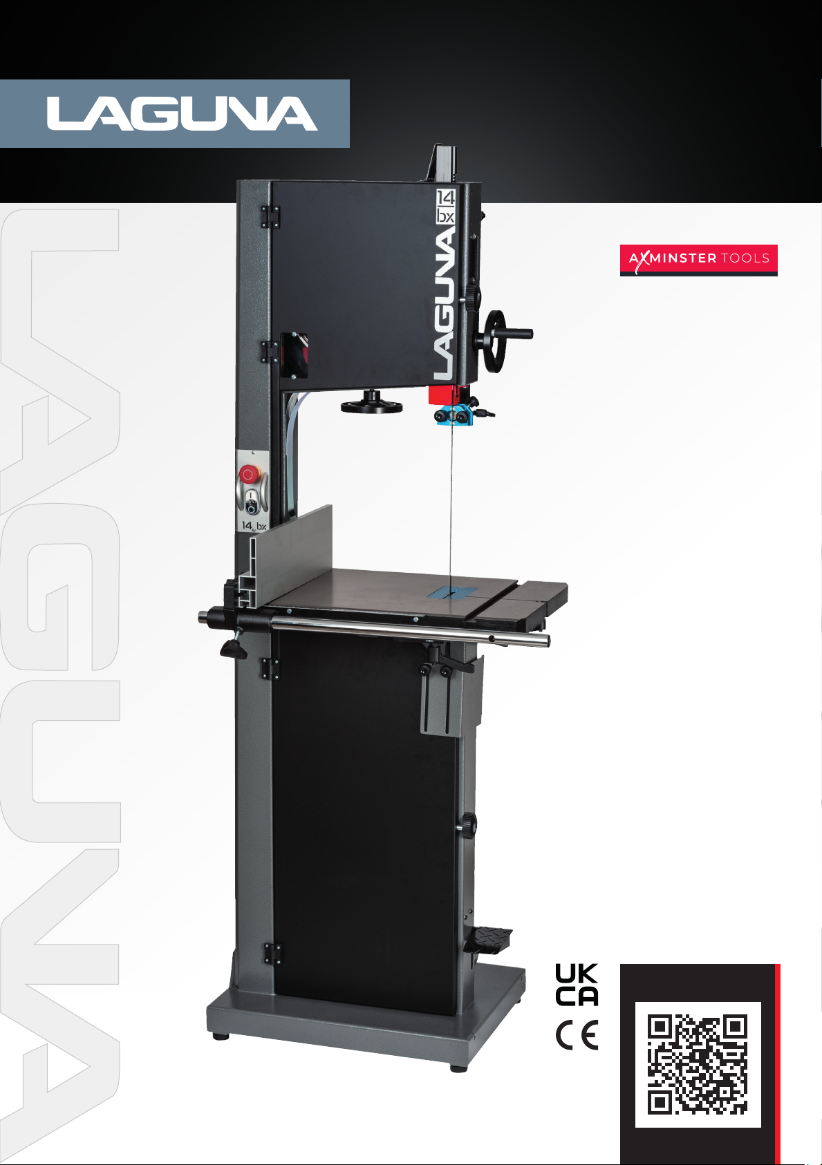
14|BX Bandsaw 230v
Code: 111783
Distributed by
N.B. Some pictures and diagrams in this manual may have buttons and electrical configurations
which differ slightly from the machine you purchased
Version: 4
Date: 1/10/25
DIGITAL MANUAL
Page 2

Contents
Safety Rules 3
Specification sheet 7
Noise emission 7
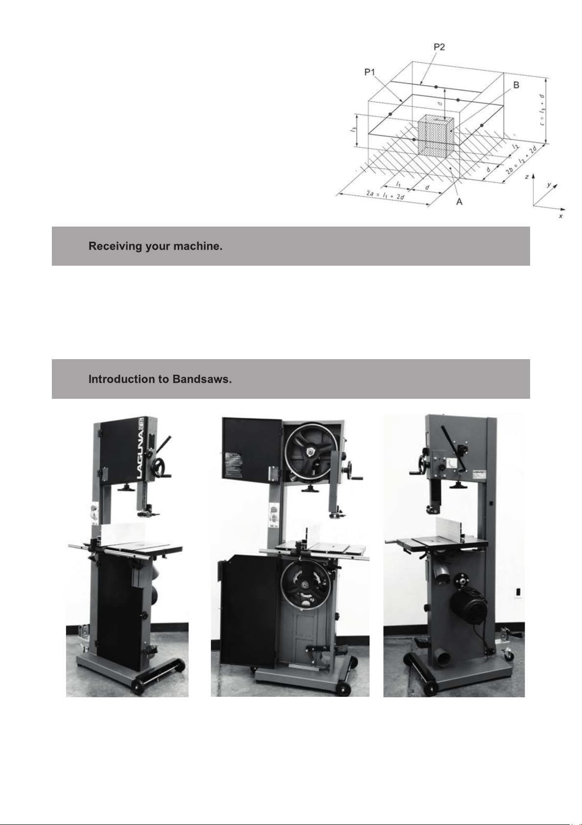
Receiving your machine 8
Introduction to Bandsaws 8
What you will receive with your Bandsaw 9
Parts of the Bandsaw 11
Where to locate your machine 15
Unpacking your machine 15
Assembly and setup 16
Maintenance 44
Troubleshooting 48
Electrical drawing 51
Exploded view drawings/parts 52
Conformity Certificates CE/UKCA 69
Warranty 70
2
Page 3
4
SAFETY RULES
1. KEEP GUARDS IN PLACE and in working order.
2. REMOVE ADJUSTING KEYS AND WRENCHES.
Form habit of checking to see that keys and ad-
justing wrenches are removed from tool before
turning it on.
3. KEEP WORK AREA CLEAN. Cluttered areas and
benches invite accidents.
4. DON'T USE IN DANGEROUS ENVIRONMENT.
Don't use power tools in damp or wet locations,
or expose them to rain. Keep work area well
lighted.
5. KEEP CHILDREN AWAY. All visitors should be
kept safe distance from work area.
6. MAKE WORKSHOP CHILD PROOF with padlocks,
master switches, or by removing starter keys.
7. DON'T FORCE TOOL. It will do the job better and
safer at the rate for which it was designed.
8. USE RIGHT TOOL. Don't force tool or attachment
to do a job for which it was not designed.
9. USE PROPER EXTENSION CORD. Make sure
your extension cord is in good condition. When
using an extension cord, be sure to use one
heavy enough to carry the current your product
will draw. An undersized cord will cause a drop
in line voltage resulting in loss of power and
overheating. Table A (on the next page) shows
the correct size to use depending on cord length
and nameplate ampere rating. If in doubt, use
the next heavier gage. The smaller the gage nu-
mber, the heavier the cord.
10. WEAR PROPER APPAREL. Do not wear loose
clothing, gloves, neckties, rings, bracelets, or
other jewelry which may get caught in moving
parts. Nonslip footwear is recommended. Wear
protective hair covering to contain long hair.
11. ALWAYS USE SAFETY GLASSES. Also use face
or dust mask if cutting operation is dusty. Eve-
ryday eyeglasses only have impact resistant
lenses, they are NOT safety glasses.
12. SECURE WORK. Use clamps or a vise to hold
work when practical. It's safer than using your
hand and it frees both hands to operate tool.
13. DON'T OVERREACH. Keep proper footing and
balance at all times.
14. MAINTAIN TOOLS WITH CARE. Keep tools sharp
and clean for best and safest performance. Fol-
low instructions for lubricating and changing ac-
cessories.
15. DISCONNECT TOOLS before servicing; when
changing accessories, such as blades, bits, cut-
ters, and the like.
16. REDUCE THE RISK OF UNINTENTIONAL STA-
TING. Make sure switch is in off position before
plugging in.
17. USE RECOMMENDED ACCESSORIES. Consult
the owner's manual for recommended acces-
sories. The use of improper accessories may
cause risk of injury to persons.
18. NEVER STAND ON TOOL. Serious injury could
occur if the tool is tipped or if the cutting tool is
unintentionally contacted.
19. CHECK DAMAGED PARTS. Before further use of
the tool, a guard or other part that is damaged
should be carefully checked to determine that
it will operate properly and perform its intended
function - check for alignment of moving parts,
binding of moving parts, breakage of parts,
mounting, and any other conditions that may
affect its operation. A guard or other part that
is damaged should be properly repaired or re-
placed.
20. DIRECTION OF FEED. Feed work into a blade or
cutter against the direction of rotation of the
blade or cutter only.
21. NEVER LEAVE TOOL RUNNING UNATTENDED.
TURN POWER OFF. Don't leave tool until it co-
mes to a complete stop.
Some dust created by power sanding, sawing, grinding, drilling and other construction activities contain chemicals
known to cause cancer, birth defects or other reproductive harm. Some examples of these chemicals are:
• Lead from lead based paint.
• Crystalline silica from bricks, cement, and other masonry products.
• Arsenic and chromium from chemically treated lumber.
Your risk of exposure varies, depending on how often you do this type of work. To reduce your exposure to these
chemicals, work in a well-ventilated area and work with approved safety equipment, such as face or dust masks
that are specically designed to lter out microscopic particles.
3
Page 4
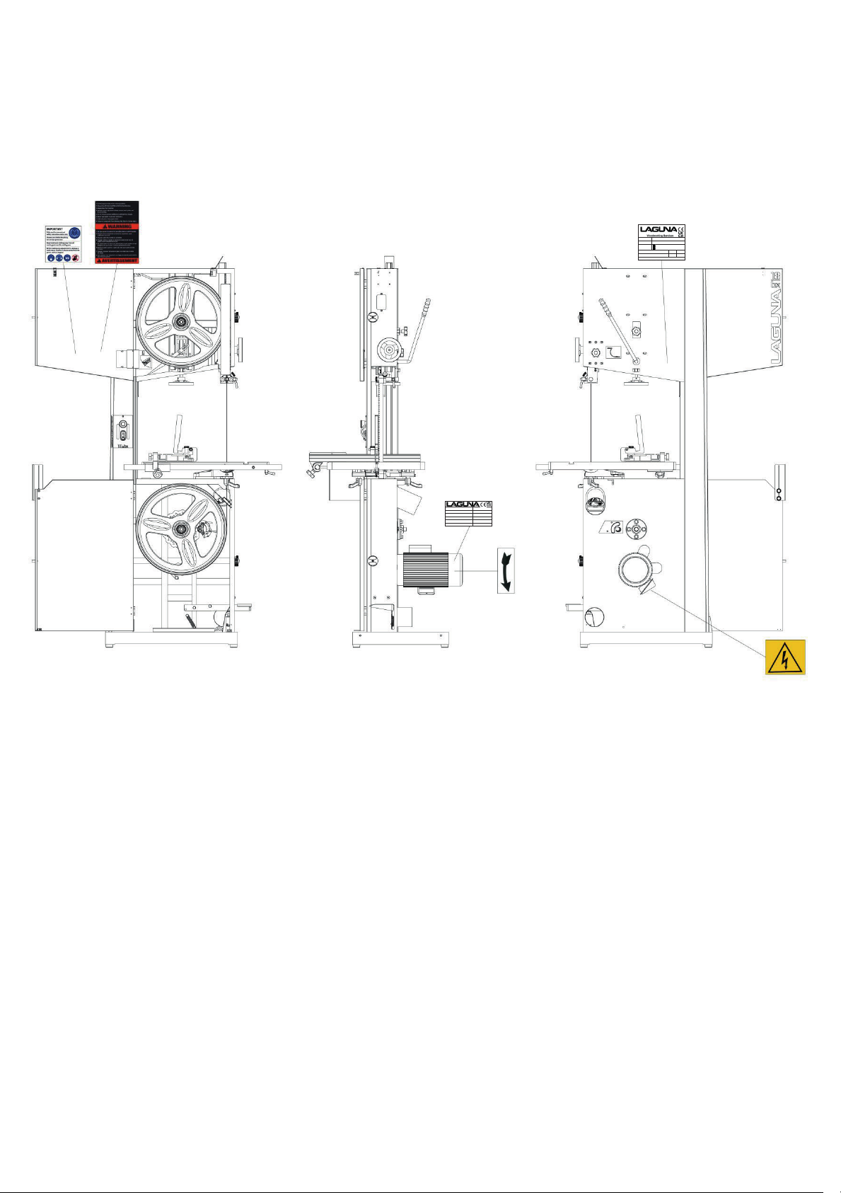
Location of warning signs
Model
14bx
Power
1~230V 50Hz 9.8A P2=1.9kw S1
Specification
v0=965 m /min SCCR=6k A
Article No.
Weight 123kg
Series No.
Year
LAGUNA TOOLS 2072 Alton Parkway. Irvine, CA 92606
www. lagunatools.com
TYPE MBAND14BX220-250-45-UK
1~230V
IEC 60034-1
50Hz
IP54
9.8A
I.CL. B
COSφ 0.97
P2=1.9kw S1
SERIES
1420 /min
3-19mm x 2914-2946mm
LAGUNA-B-0003
5
4
Page 5

The woodworking band saw is a saw with a long, sharp blade consisting of a continuous band
Woodworking band saw
of toothed metal stretched between two wheels to cut material. They are used principally in
woodworking and lumbering. These bandsaws have two wheels rotating in the same plane,
one of which is powered. The blade itself can come in a variety of sizes and tooth pitches
(teeth per inch, or TPI), which enables the machine to be highly versatile and able to cut a
wide variety of wood materials.
6
5
Page 6
Emergency stop switch
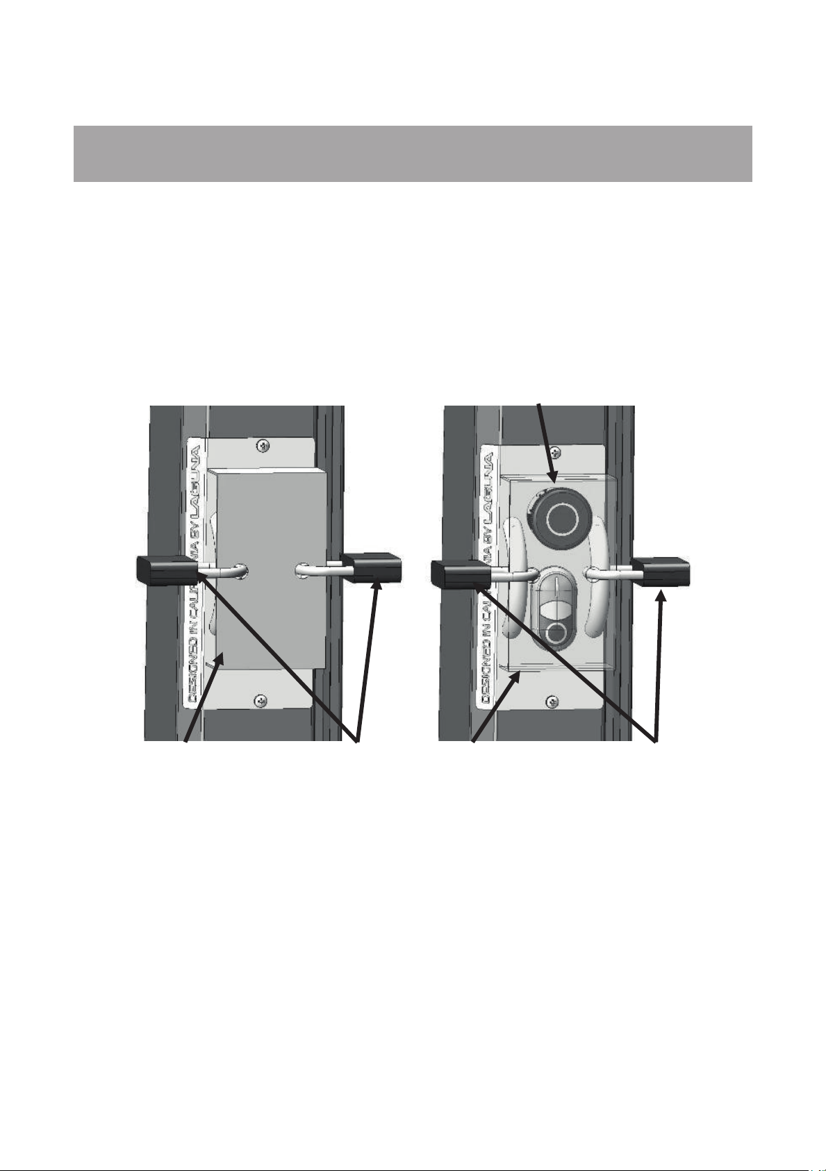
Locking the bandsaw.
It is strongly recommended that the bandsaw is never be left unattended in the unlocked
condition.
To lock the machine it is recommended that a cover (not supplied) is made to lock the control
panel. We have supplied two concepts for locking the panel (see below). The cover can be
made from wood or plastic.
First, push down the emergency stop. Then lock the cover together by putting padlocks [not
included] on the two handles on the control panel. To safeguard your machine from
unauthorized operation and accidental starting by young children, the use of padlocks is
strongly recommended
Wooden safety cover Padlock
Plastic safety cover Padlock
7
6
Page 7

MBAND14BX110-175
MBAND14BX220-250
Motor voltage/hp
Breaker
15 amp
15 amp
Throat
13 5/8" (346mm)
13 5/8" (346mm)
Table cast iron
16" x 21 1/2" (406.4mm x
546mm)
16" x 21 1/2" (406.4mm x
546mm)
Table tilt
- 7 degrees + 45 degrees
- 7 degrees + 45 degrees
Miter slot
3/8" x 3/4" (9.525mm x
19.05mm)
3/8" x 3/4" (9.525mm x
19.05mm)
Table height
38" (965mm)
38" (965mm)
Fly wheel
Cast iron
Cast iron
Resaw capacity
13" (330.2mm)
13" (330.2mm)
Minimum blade length
114 3/4" (2,914mm)
114 3/4" (2,914mm)
Maximum blade
length
116" (2,946mm)
116" (2,946mm)
Maximum blade width
3/4" (19mm)
3/4" (19mm)
Minimum blade width
1/8" (3mm)
1/8" (3mm)
Guides
Laguna ceramic
Laguna ceramic
Height
70 1/2" (1,790mm)
70 1/2" (1,790mm)
Machine Dimensions
29 3/4" x 26 7/8" (755mm x
(576mmx446mm)
29 3/4" x 28 1/16" (755mm x
(576mmx446mm)
Machine Dimensions
mobility kit
36 5/8" x 26 7/8" (930mm x
36 5/8" x 28 1/16" (930mm x
Weight gross
282 lbs (128 kg)
292 lbs (132.7 kg)
Weight net
260 lbs (118 kg)
270 lbs (122.7 kg)
Package size (W x D x
H)
73 1/8" x 26 1/2" x 24 5/16"
(1857mm x 673mm x 618mm)
73 1/8" x 26 1/2" x 24 5/16"
(1857mm x 673mm x 618mm)
Mobility kit
Optional
Optional
Industrial work light
Optional
Optional
Specification.
230V / 1 3/4 HP 1Ph 50Hz 230V / 2 1/2 HP 1Ph 50Hz
(W x D) Base
Footprint
with mobility kit (W x
D)
Base Footprint with
683mm)
22 11/16" x 17 9/16"
683mm)
33" x 20 1/2" (838mm x 521mm)
713mm)
22 11/16" x 17 9/16"
713mm)
33" x 20 1/2" (838mm x 521mm)
Noise emission.
Equivalent A-weighted Sound pressure level according to EN ISO 3746: 73.56 dB(A)
Uncertainty, K in decibels: 4.0 dB (A) according to EN ISO 4871
10
7
Page 8
The figure quoted is emission levels and are not necessarily safe
working levels. Whilst there is a correlation between the emission
and exposure levels, this cannot be used reliably to determine
whether or not further precautions are required. Factors that
influence the actual level of exposure of the workforce include
characteristics of the work room, the other sources of noise, etc.
i.e. the number of machines and other adjacent processes. Also
the permissible exposure level can vary from country to country,
This information, however, will enable the user of the machine to
make a better evaluation of the hazard and risk.
It is probable that your machine will be delivered by a third party. Before you unpack your new
machine, you will need to first inspect the packing, invoice and shipping documents supplied
by the driver.
Ensure that there is no visible damage to the packing or the machine. You need to do this
prior to the driver leaving. All damage must be noted on the delivery documents and signed
by you and the delivery driver. You must then report the damage to the sel
ler within 24 hours.
11
8
Page 9
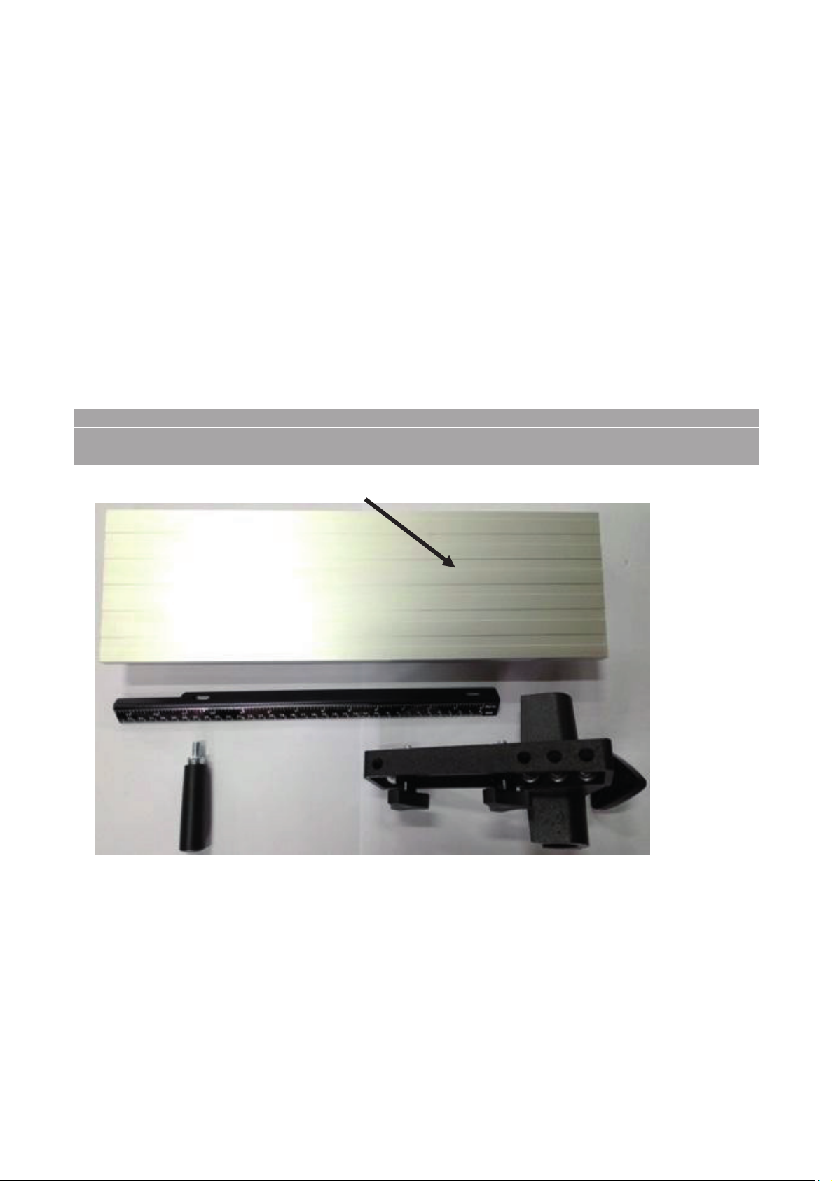
Fence
Fence parts
This bandsaw is designed to give you years of safe service. Read this owner’s manual in its
entirety before assembly or use.
The bandsaw is generally defined as a saw blade in the form of an endless steel band that
rotates around two or more wheels. This blade is a continuous metal band with teeth on one
side. As the wheels rotate, so does the band, which creates the continuous sawing action.
Because the direction of the blade is always downward toward the table, there is little danger
(except for special cuts) that the wood will be thrown back at the operator, which is called a
kickback. "There is always danger of kickback when a circular saw is being used".
For safety reasons many woodworkers prefer the bandsaw especially when cutting small
pieces. The unique feature of the bandsaw is that the work piece can be rotated around the
blade creating a curve. It is the tool most often used when curves have to be cut in wood.
Because the bandsaw blade is fairly thin, it can cut thick stock with a minimum of horsepower.
For this reason the bandsaw is often used when valuable pieces of wood are made into a thin
piece of veneer.
What you will receive with your Bandsaw.
12
9
Page 10
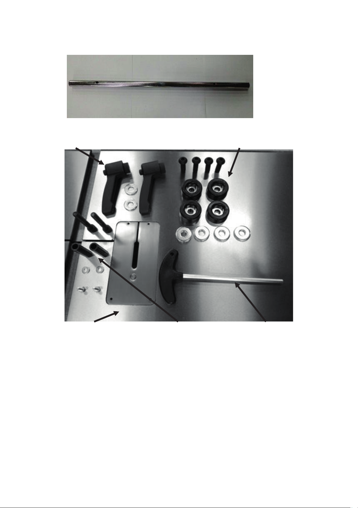
Fence guide bar
Table ratchet handles & washers Rubber feet and fixings
Table Fence guide bar attachment parts T bar
10
13
Page 11
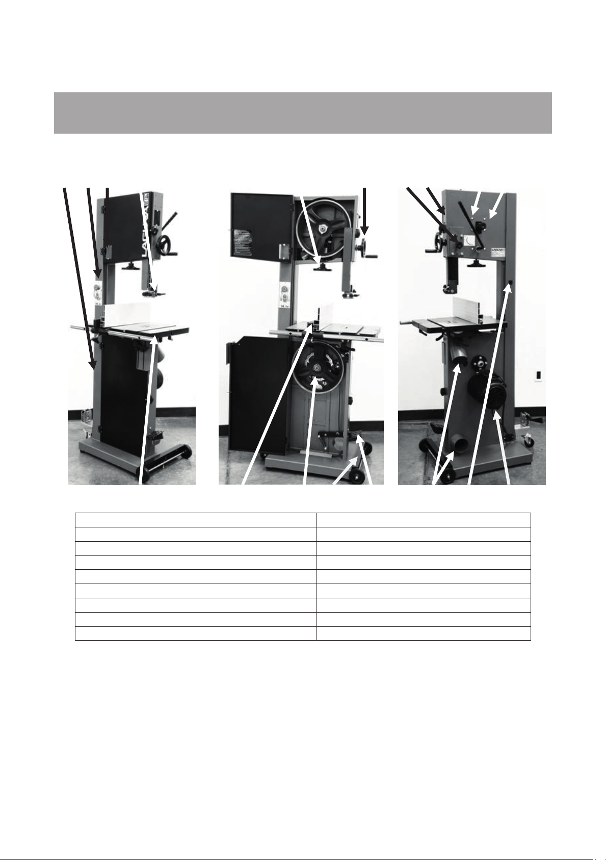
4 2 1 9
5 8
16 6 12 13
11 15 3
1. Tension indicator window
2. Switch
3. Motor
4. Frame
5. Blade tension handle
6. Blade tracking window
7. Cast iron table
8. Blade guide adjustment hand wheel
9. Blade guide
Parts of the Bandsaw.
Note: The mobility kit and light are optional.
7
The bandsaw does not have many parts. The major parts are discussed in this manual. If you
are not familiar with the bandsaw, take the time to read this section and become familiar with
the machine.
10 17 14 18
10. Rip fence assembly
11. Dust port 4”
12. Quick-release blade tension lever
13. Blade tracking knob
14. Optional mobility kit
15. Power socket
16. Blade guide shaft lock knob
17. Flywheel
18. Brake foot pedal
14
11
Page 12
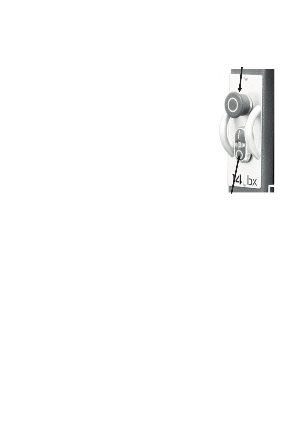
1. Tension indicator / window.
Tension indicators are designed to indicate the compression of a
spring. As a rule, the greater the spring compression, the greater
Emergency stop
button
the tension on the blade. The tension scale does not register until
the blade is relatively taut and is located on the inside of the body
of the bandsaw. The tension scale is a general reference and not
a rule. The tension indicator is visible with the upper door closed
by looking through the tension indicator window.
2. Switch.
To start the machine press the "I" button on the start stop switch.
To shut off the machine press the "O" on the start stop switch.
When the safety switch is pressed it stops the power to the motor.
To reset it, twist and it will pop out and allow power to be supplied
to the motor.
3. Motor.
The bandsaw is supplied with a 1 3/4 hp, or 2 1/2 hp,
220V motor. It drives the lower flywheel through a drive belt.
4. Frame.
The frame of the bandsaw is a U-shaped frame, which houses all
Start / Stop buttons
the parts of the machine. This is the heart of the bandsaw and has
to be very rigid, as it takes the strain of the blade being tensioned.
5. Blade tension handle.
The blade tension handle moves the blade tension and tilt assembly vertically. The vertical
action compresses a spring that ensures that the blade tension is constant and will not
change dramatically as the blade length increases due to the heat generated by the cutting
action.
6. Blade tracking window.
There is a blade tracking window on the side of the frame that allows the edge of the upper
flywheel to be viewed. This allows the tracking of the blade to be achieved with the door
closed.
7. Cast iron table.
The table supports the work piece and can tilt (-7 degrees to +45 degrees) to produce cuts at
various angles. It has a groove to the right-hand side of the blade, which is used to guide the
miter gauge. In the center there is a table insert which the blade passes through. Should the
blade wander off center, this table insert will protect the blade from damage, as it is soft and
should not damage the blade. The table also supports the adjustable fence, which is used for
parallel cuts. There is a nut and bolt that joins both sides of the table and stops the table from
warping. The nut and bolt must always be fitted in the table and only removed when removing
or fitting a blade.
15
12
Page 13

8. Blade guide adjustment hand wheel.
The upper blade guides are attached to the blade guide shaft. The shaft is vertically
adjustable with a hand wheel. The guides should be adjusted so the guides are just above the
wood being cut. This gives the blade maximum stability and is also the safest way to operate
the bandsaw.
9. Blade guides.
There are two sets of blade guides, one above and one below the table. The function of the
guides is to give the blade stability and ensure that the blade movement left/right,
forward/back is kept to a minimum. The guides above the table are fitted to a shaft that has
vertical adjustment. The upper guides are adjustable so that the guides are held just above
the job being cut. This gives the blade the maximum amount of stability and also keeps the
amount of blade that is exposed to a minimum. The guides have ceramic inserts that can be
adjusted for almost zero clearance.
10. Rip fence assembly.
The rip fence assembly consists of a guide rail, cast knuckle, fence attachment casting, rule
and a high-low fence. The guide rail is attached to the table side. It guides the fence assembly
across the table. The cast knuckle slides on the guide rail and is lockable in any position to
suit the width of cut. The fence attachment casting is attached to the cast knuckle with three
screws that when loosened allow the fence to be adjusted for drift. The fence is attached to
the fence attachment casting with two studded knobs that allow the fence to be adjusted
laterally across the table to suit the job being cut. The fence can be fitted in the low 1/2" or
high 5 1/2" position.
There is a rule that is fitted to the side of the table and can be used as a quick guide on the
distance that the fence is from the blade.
Note. The rule will have to be adjusted each time the fence is adjusted for drift, as this will
change the distance the fence is from the blade.
11. Dust ports 4".
The bandsaw produces a lot of sawdust, so extraction is very important. This is achieved by
connecting a 4" dust extraction hoses with a minimum capacity of 1,000 CFM to the two dust
ports located at the back of the machine. The stronger the suction from the dust collector, the
better for you and the machine.
12. Quick-release blade tension lever.
There is a quick-release tension lever at the back of the bandsaw. The lever is a convenient
way of quickly releasing the tension on the blade and speeds up blade change dramatically.
13. Blade-tracking knob.
The blade-tracking knob is located at the back of the bandsaw and is used to adjust the blade
tracking. The knob must be locked once the adjustment is completed.
16
13
Page 14
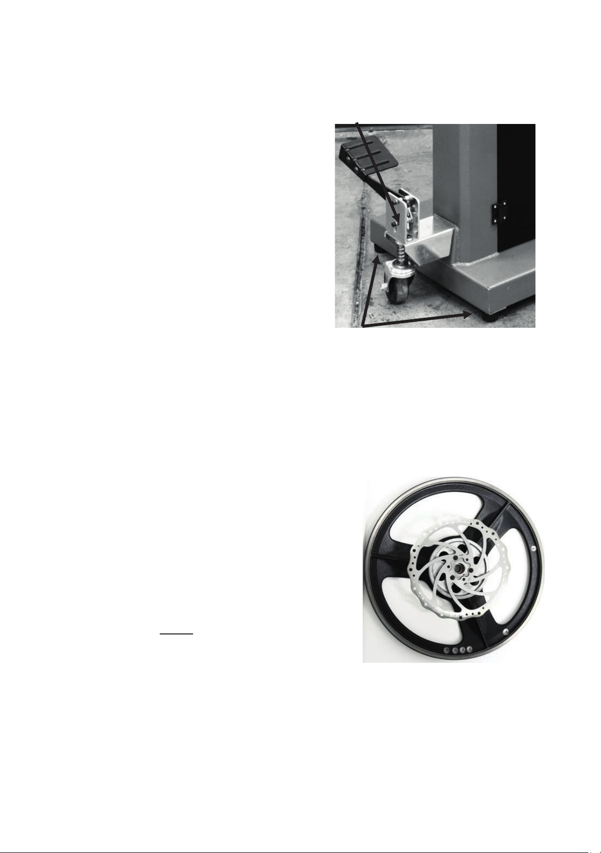
14. Optional mobility kit.
Swivel wheel assembly
The optional mobility kit is fitted to the base of the
bandsaw and consists of two fixed wheels at the
front of the bandsaw and a swivel wheel at the
back of the band saw. The swivel wheel is
activated and deactivated with a foot lever.
With the swivel wheel deactivated, the bandsaw
sits on two rubber feet.
15. Optional light.
The optional light is fitted with four screws through
pre-drilled holes at the top of the bandsaw. The
bandsaw is provided with a 220V socket
that the light can be connected to.
16. Blade guide shaft lock knob.
The upper blade guide is fixed to the blade guide
Rubber feet
shaft, which is vertically adjustable. Once the
guides have been adjusted vertically, the shaft is locked in position with the lock knob.
17. Flywheel.
The blade is suspended over two wheels that are covered with rubber called a "tire". The tire
cushions the blade and protects the teeth from coming in contact with the metal of the
flywheel. The lower wheel is the drive wheel and is attached to the motor with a rubber drive
belt. The lower flywheel powers the blade and pulls the blade down through the work piece.
The top wheel has two functions. One function is to balance or track the blade on the wheels,
and the second one is to tension the blade. Both functions are adjustable.
18. Brake.
The bandsaw is provided with a brake that is operated
by applying the foot pedal. When the foot pedal is
applied, the power is removed from the motor and the
flywheel is slowed by the disc break.
19. Guards.
When running, the blade can be very dangerous, and
the amount of blade that is exposed must be kept to a
minimum. The machine is supplied with a number of
guards, all of which MUST
be installed and used while
the machine is running. There is a guard that is
attached to the lower door and is adjustable vertically
once the door is closed. There is a guard on the guide
Disc break on flywheel
vertical adjustment shaft.
17
14
Page 15
v0=965 m /min SCCR=6k A
Series No.
Year
LAGUNA TOOLS 2072 Alton Parkway. Irvine, CA 92606
www. lagunatools.com
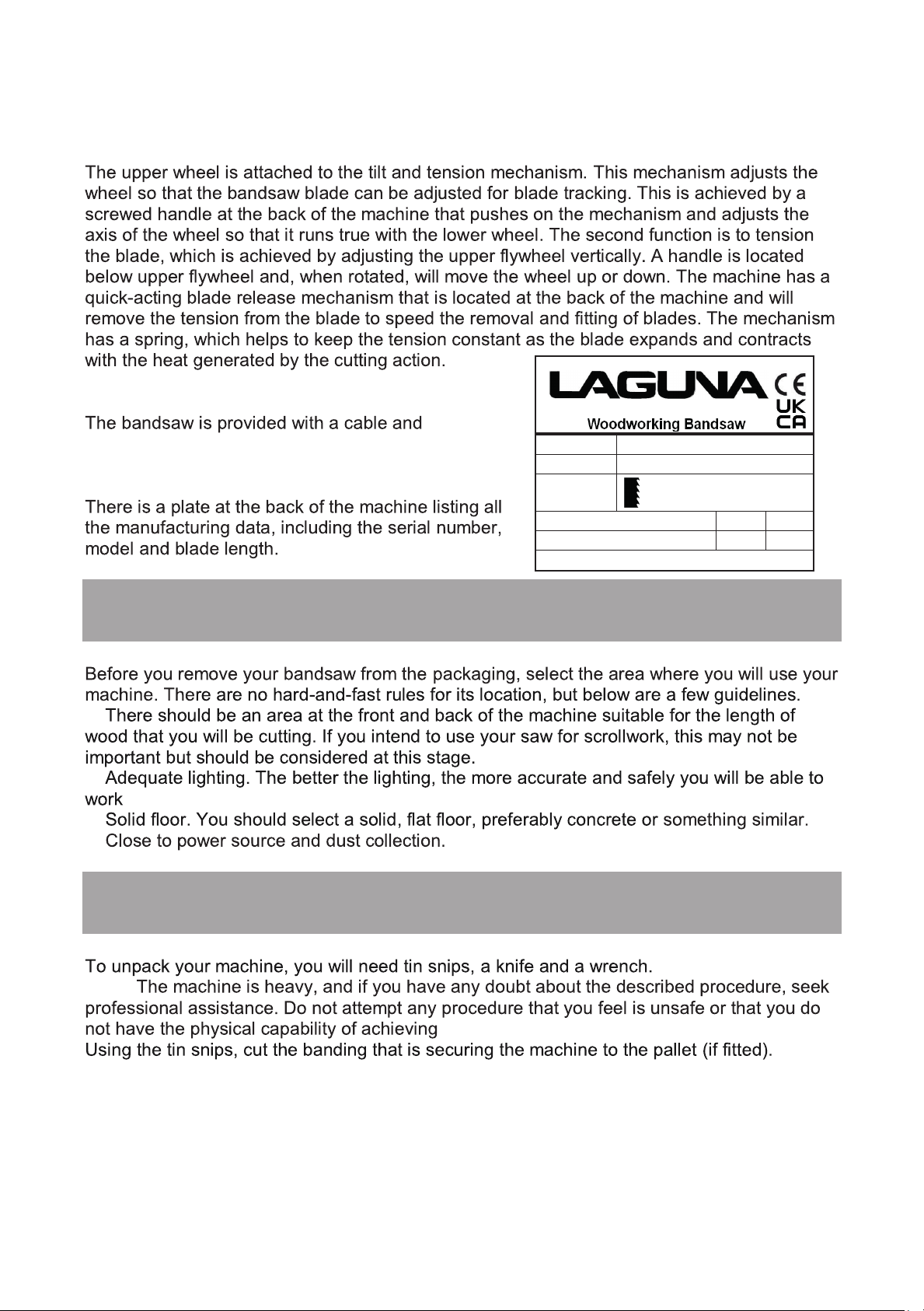
20. Blade tilt and tension mechanism.
21. Electrical connection.
22. Identification.
plug.
Model 14bx
Power
Specification
Article No. LAGUNA-B-0003 Weight 123kg
1~230V 50Hz 9.8A P2=1.9kw S1
3-19mm x 2914-2946mm
1.
2.
3.
4.
Note:
Where to locate your Bandsaw.
Unpacking your Bandsaw.
.
WARNING: EXTREME CAUTION MUST BE USED BECAUSE THE BANDING WILL
18
15
Page 16
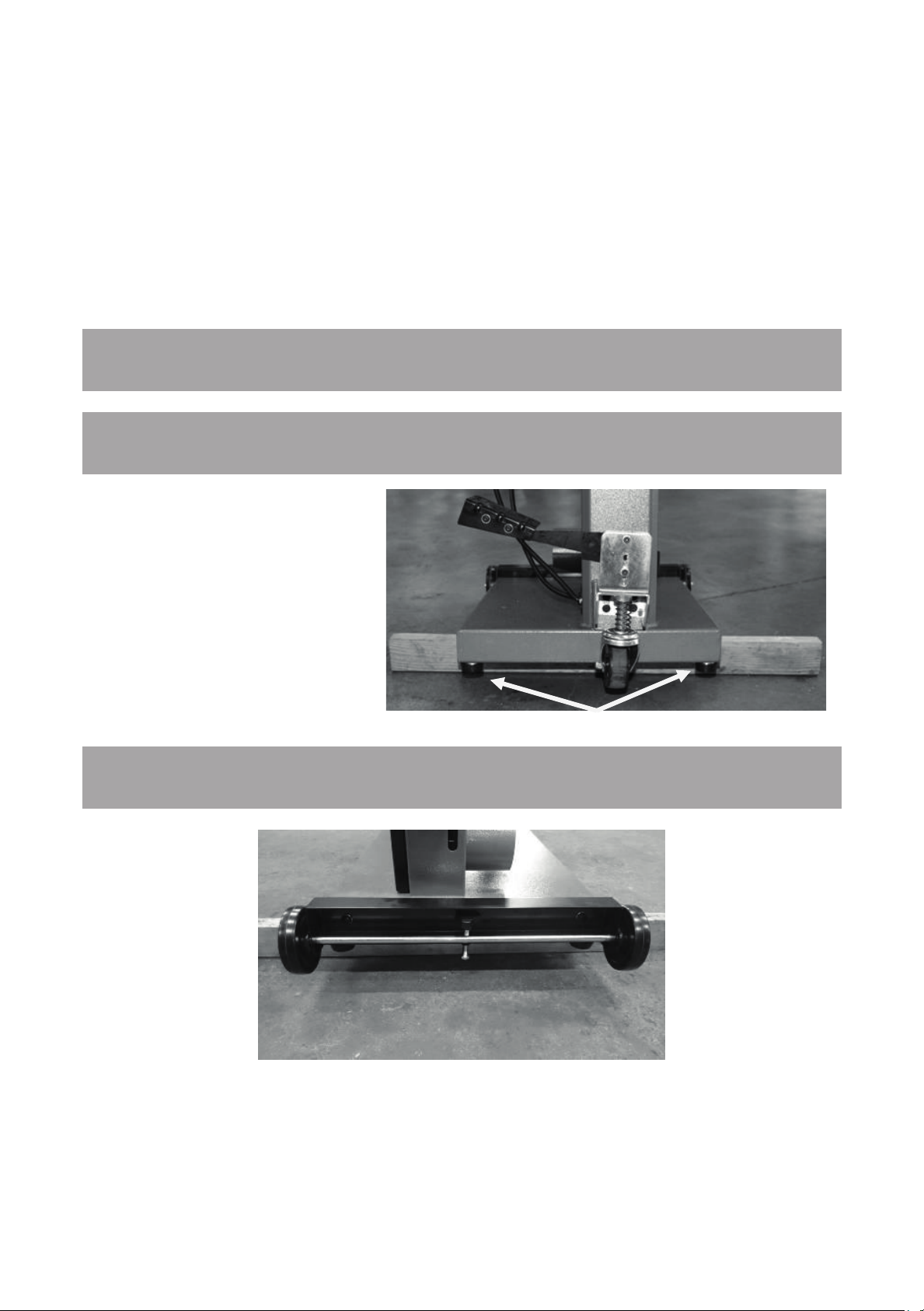
Bandsaw supported on wooden block
Rubber feet
SPRING AND COULD CAUSE INJURY.
Your bandsaw will be shipped in custom packaging consisting of a heavy-duty cardboard box
and Styrofoam internal packaging.
1. Open the cardboard box and remove the loose parts and top Styrofoam.
2. Lift the bandsaw out of the packaging. You will need two or more people, as the bandsaw
is heavy.
3. Lift the bottom Styrofoam out and remove the parts that are packaged under the bandsaw
and packaging.
Assembly and set up.
Assembling the rubber feet.
Method 1.
Fit the rubber feet to the bandsaw
prior to removing it from the
packaging.
Method 2.
1. Support the bandsaw on
wooden blocks.
2. Assemble the rubber feet with
the fixings provide both at front
and back of the bandsaw.
Assembling the optional mobility kit
19
16
Page 17
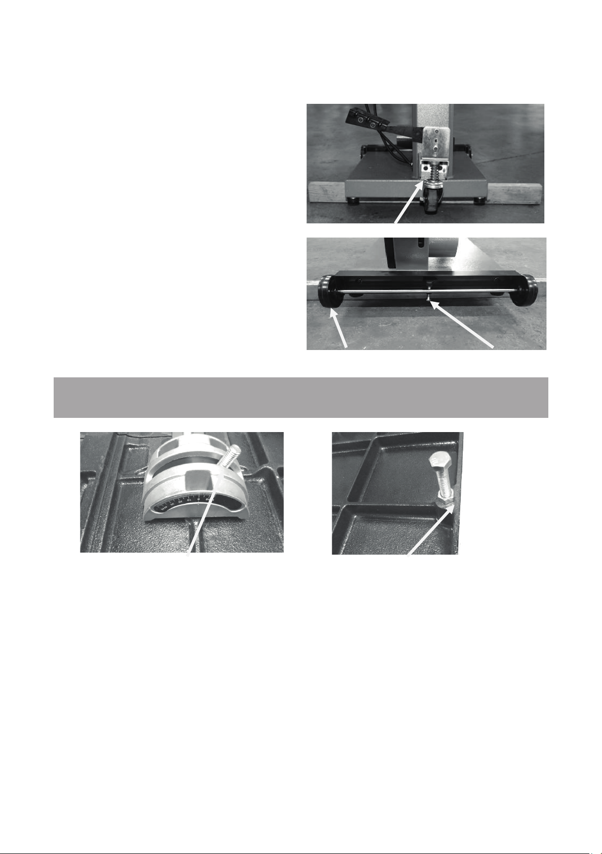
Trunion clamp stud
Tilt stop bolt
Rear swivel wheel
Front wheels Locking screw
1. Support the bandsaw on wooden blocks.
2. Fit the swivel assembly to the back of the
bandsaw with the provided bolts.
3. Fit the front wheels to the front of the
bandsaw with the bolts provided and remove
the two rubber feet that are close to the front
wheels..
Note. Never operate the bandsaw with the
mobility kit engaged or the front wheel
assembly locking screw not engaged.
Fitting the table.
It is possible to fit the table to the bandsaw with one person but far easier if you have two
people, one to lift the table and one to guide the trunion clamp studs.
17
20
Page 18
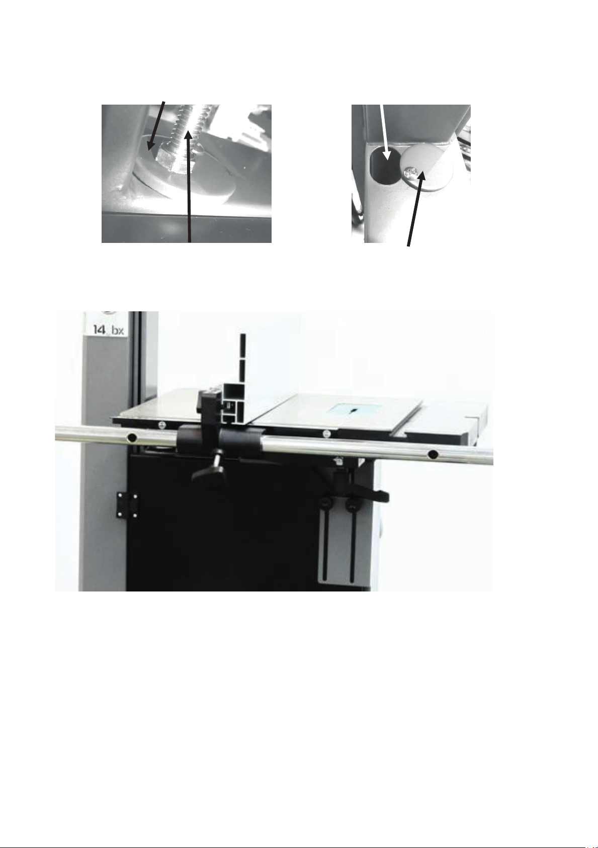
Tilt blanking disc
Tilt stop bolt
Table tilt hole
Tilt blanking disc
Table mounted to the bandsaw
The table has a reference stop bolt that is used to quickly align the table after tilting. The stop
bolt hits the tilt-blanking disc when it is positioned over the table tilt hole. When the tilt
blanking disc is moved away from the hole, it allows the tilt stop bolt to pass through the table
tilt hole, and the table can be moved to the maximum amount of tilt (-7 degrees).
21
18
Page 19
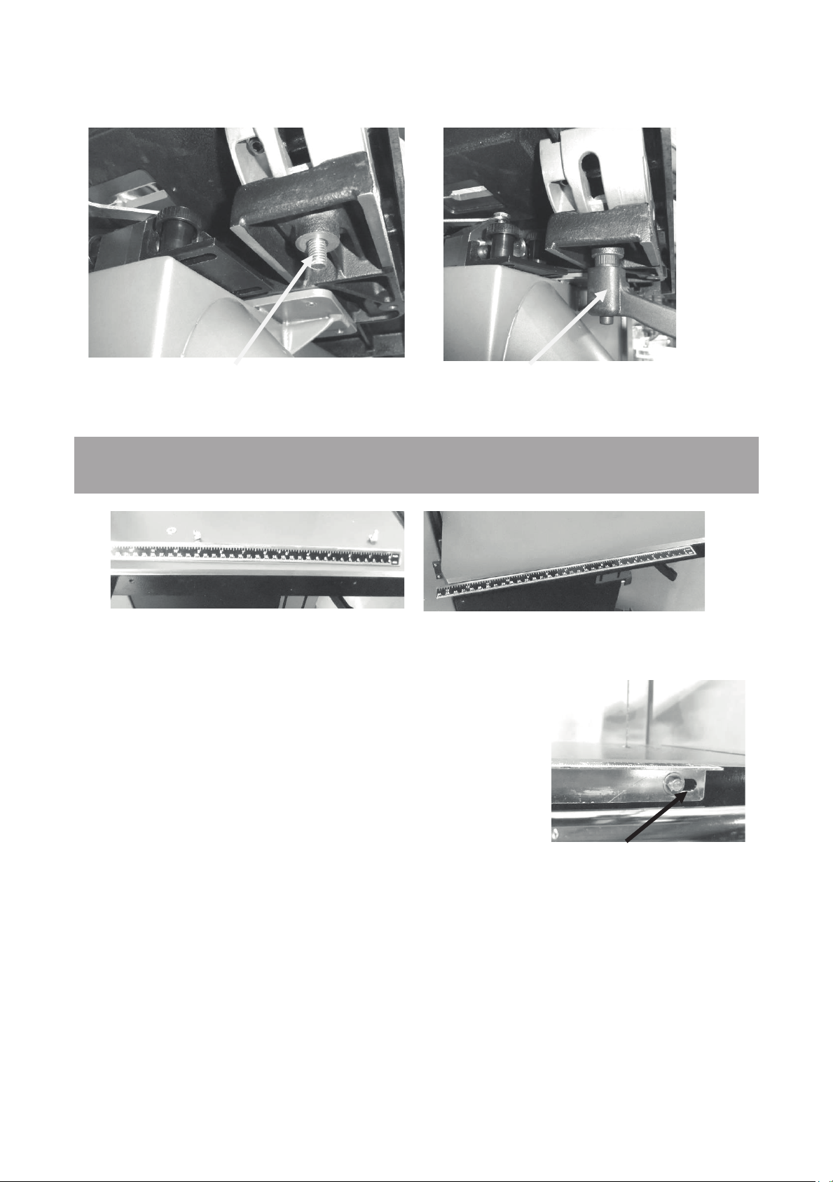
Trunion clamp stud
Ratchet handle
Table rule with fixings
Table with rule mounted
Rule adjustment slot
With the table fitted to the trunions, assemble the two ratchet handles and flat washers.
How to adjust the table for square to the blade. This will be detailed later in the manual.
Fitting the table rule.
Attach the rule to the table with the fixings supplied. Do not
fully tighten the bolts, as the position of the rule will have to be
adjusted to suit the blade, which will be detailed later in the
manual.
22
19
Page 20
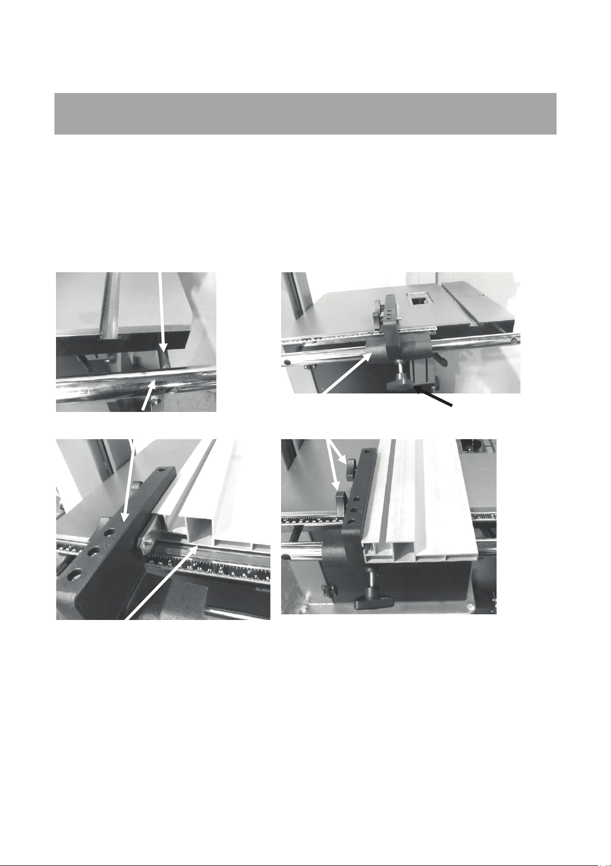
Spacer
Fence bar
Fence support
Fence in low position
Lock knob
Fitting the fence.
1. Fit the fence bar to the table with the screws and spacers supplied.
Note. The distance between the fixing holes and the end of the bar is not symmetrical, and
the end that has the longest distance must be at the back of the bandsaw (closest to the
column).
2. Slide the fence support onto the fence bar and fit the fence support clamp screw.
3. Slide the fence onto the clamping strip.
4. Lift the fence just clear of the table and secure it in position with the clamping screws.
Fence support
Fence support lock knob
Fence clamped in low position
23
20
Page 21
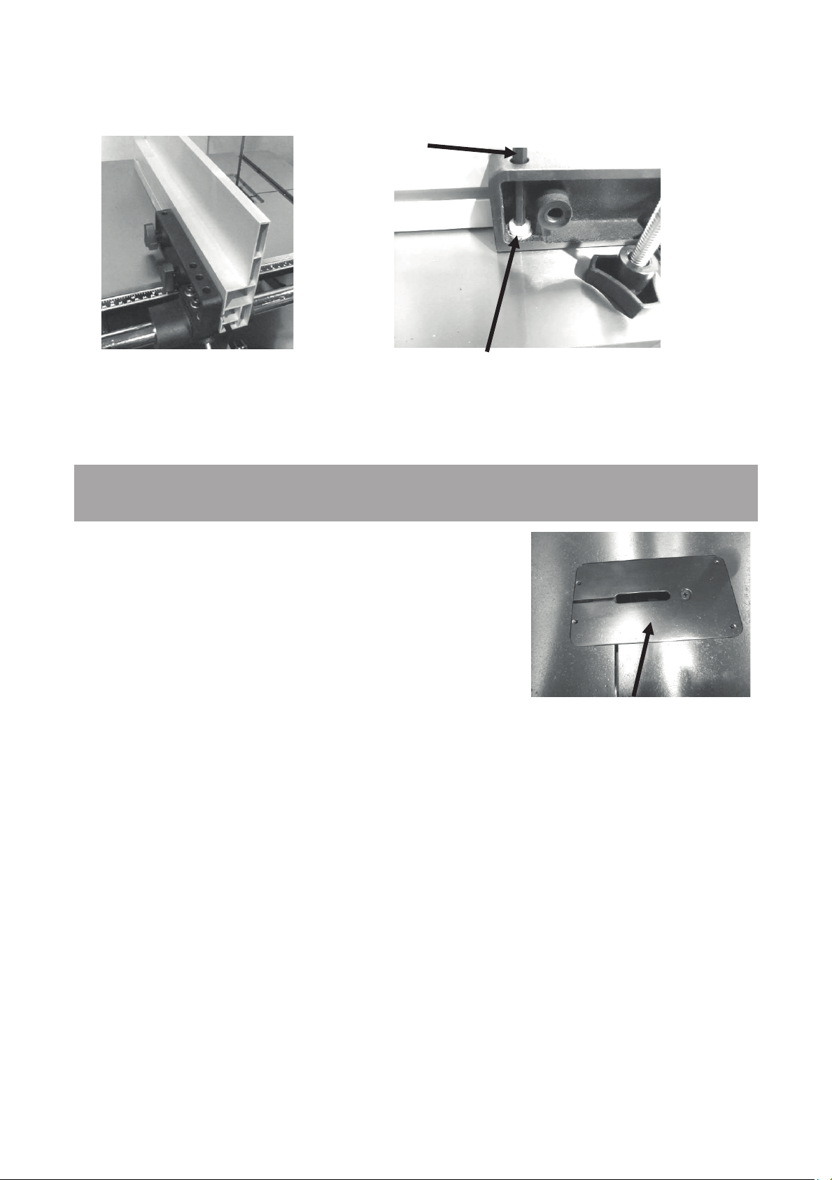
Fence in high position
Allen key
Support Allen screw
Table insert
The fence support and the fence are held off the table with a nylon-support Allen screw. This
screw ensures that the fence and the fence support do not damage the table. The screw is
adjustable to compensate for wear.
Note. The fence clamp screw is shown removed.
Fitting the table insert.
The machine is supplied with a removable table insert that
is held in position with a screw. The table insert is removed
when blades are removed or fitted to the machine. The
insert is made of soft aluminium so that if the blade wanders
and contacts the insert, there is less chance of damaging
the blade. Adjusting screws are provided to adjust the insert
vertically level with the table. The insert comes factory set,
but should adjustment become necessary, place the insert
in the table with the screw fitted. Place a straight edge
across the table and insert and adjust the screws so that
the table insert is level with the top of the table.
24
21
Page 22
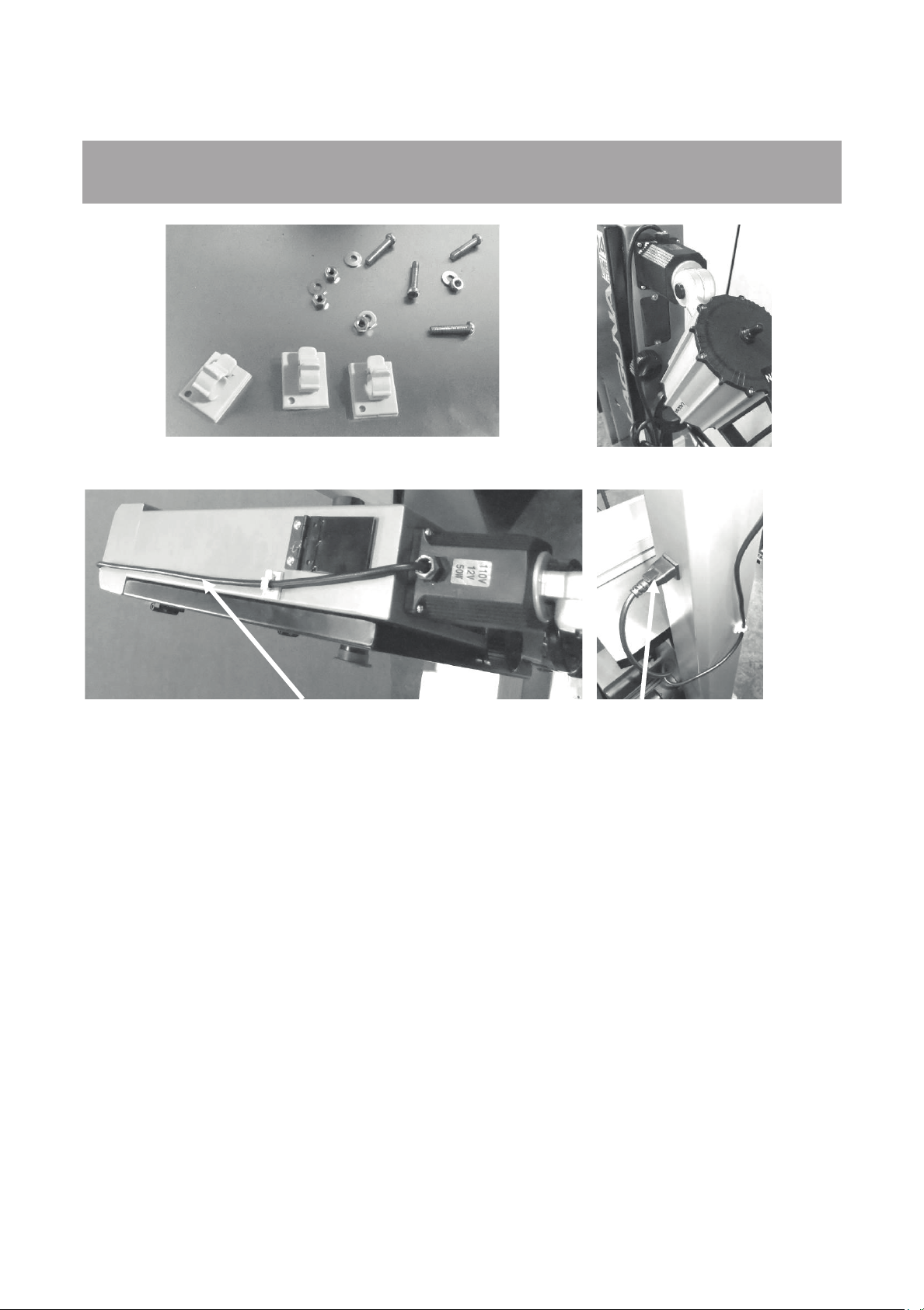
position
Fitting the optional light.
Fixing screws and cable clips
Light fitted in
Suggested cable route
Light plugged into
socket
The light is fitted to the top of the bandsaw as shown. The light is supplied with a plug.
The cable must be held in position with the clips provided and positioned so that the
cable is safe and will not in any way come close to the blade or cabinet door. Above
is the suggested cable route. Use the sticky cable clamps to secure the cable along
the top of the bandsaw. Ensure that the cable is not over the vertical shaft hole, as it
could be damaged when the shaft exits the hole.
25
22
Page 23
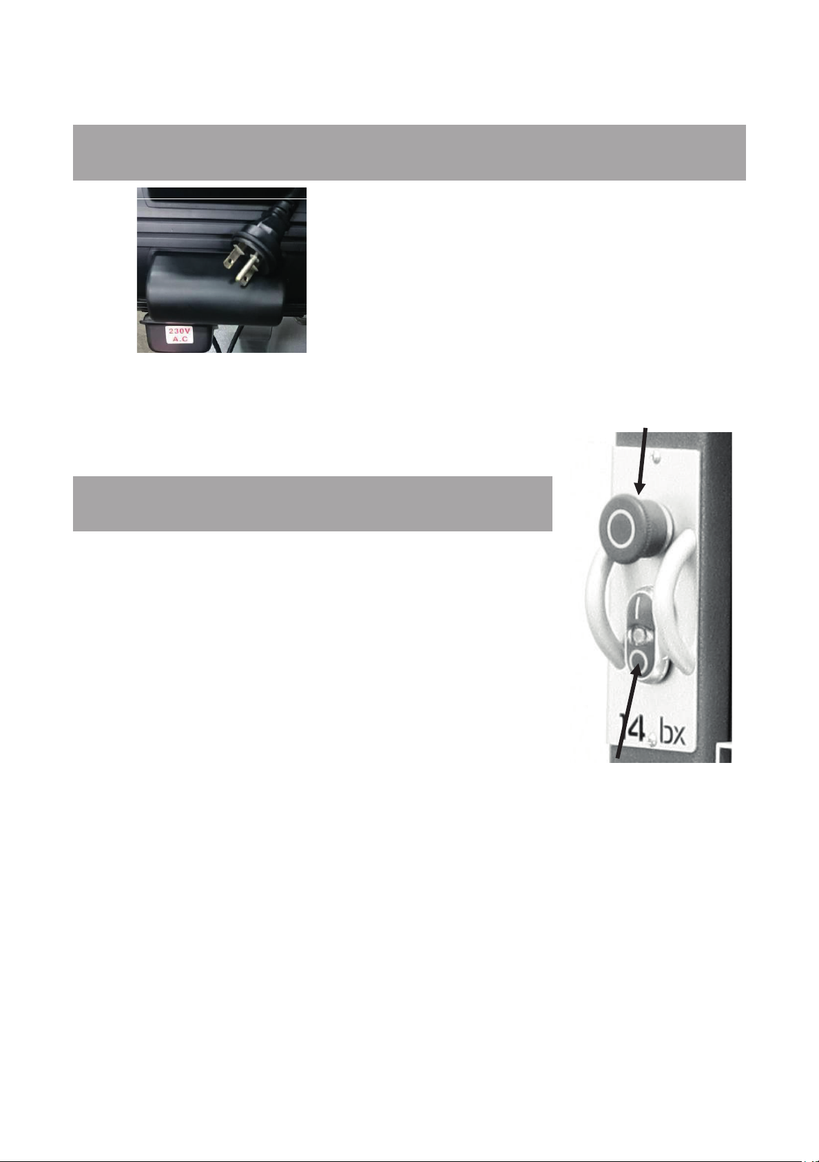
Connecting the bandsaw to the electricity supply.
220V Electrical plug and Cable
The bandsaw is supplied pre-wired with a 220V plug.
It is recommended that the bandsaw be connected to a
Emergency stop
button
15 amp breaker. The start/stop switch activates the motor .
Testing the bandsaw.
1. Close the doors.
2. Check that the red safety switch is in the fully out position.
3. Check that the machine is clear of all tools and other loose
objects.
4. Check that all the adjusting and locking handles are tight.
5. Check that there is no blade fitted; it is far safer to test the
machine without a blade fitted.
6. Connect the bandsaw to the electricity supply.
7. Start the bandsaw by pressing the green start button.
8. The lower flywheel is now turning.
9. Now is the time to check that the stop switch is functioning
correctly.
10. With the machine running (no blade fitted), operate the red
Start / Stop buttons
stop switch by pressing toward the machine. The motor should have the power turned off and
slow down.
11. If the switches fail to operate correctly, do not use the machine until the fault has been
corrected.
12. With the motor running, press the red emergency stop button. The motor should have the
power turned off and slow down.
13. With the motor running, press the foot break pedal.
The motor should have the power removed and come to a stop.
Should the bandsaw fail the test, it must not be used until the fault has been corrected.
26
23
Page 24

Before starting the bandsaw.
Read and understand the instruction manual before operating the saw.
1. If you are still not thoroughly familiar with the operation of the bandsaw, get advice from a
qualified person.
2. Make sure the machine is properly grounded and that the wiring codes are followed.
3. Do not operate the bandsaw while under the influence of drugs, alcohol or medicine or if
tired.
4. Always wear eye protection, safety glasses or a safety shield, and hearing protection.
5. Wear a dust mask; long-term exposure to the fine dust created by the bandsaw is not
healthy.
6. Remove your tie, rings, watch and all jewelry. Roll up your sleeves; you do not want
anything to get caught in the saw.
7. Make sure that the guards are in place and use them at all times. The guards protect you
from coming in contact with the blade.
8. Make sure that the saw blade teeth point downward toward the table.
9. Adjust the upper blade guard so that it is just clearing the material being cut.
10. Make sure that the blade has been properly tensioned and tracked.
11. Stop the machine before removing the scrap piece from the table.
12. Always keep your hands and fingers away from the blade.
13. Make sure that you use the proper size and type of blade.
14. Hold the work piece firmly against the table. Do not attempt to saw stock that does not
have a flat surface facing down, unless a suitable support is used.
15. Use a push stick at the end of a cut. This is the most dangerous time because the cut is
complete and the blade is exposed. Push sticks are commercially available.
16. Hold the wood firmly and feed it into the blade at a moderate speed.
17. Turn off the machine if you have to back the material out of an uncompleted or jammed
cut.
27
24
Page 25
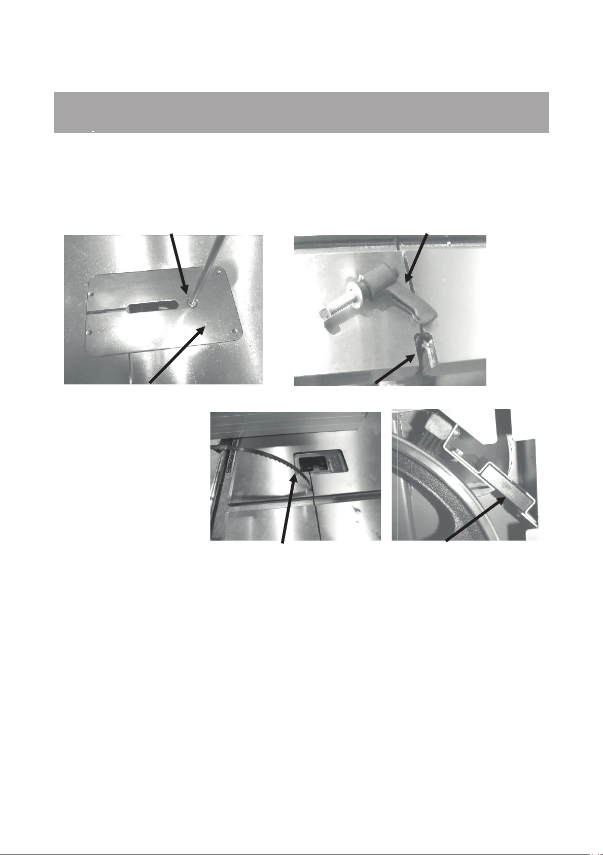
Clamp screw
Throat plate
Table split clamp screw
Table split clamp slot
Plastic blanking block
Blade in table split
Fitting a blade to the bandsaw.
A lot of people do not like to change the blades and go to great lengths to avoid doing it. To
use the bandsaw to its greatest advantage, you will have to use the appropriate blade and
track it quickly. This is a habit that can be easily developed. If you use a step-by-step method
of tracking and tensioning, the procedure should only take a minute or two. Be careful when
using blades, especially wide ones. Always use gloves and safety glasses.
Disconnect the power
from the bandsaw.
1. Remove the throat plate
by removing the clamp
screw.
2. Remove the table split
clamp ratchet handle.
3. Remove the plastic
blanking plate.
4. Adjust the side guide
and back guide out as far as they will go (both upper and lower guides). This will ensure that
they do not interfere with the blade while you are fitting, tracking and tensioning the blade.
5. Uncoil the blade. Remember to use gloves and safety glasses. The blade may have dirt or
oil on it, so use a clean rag to clean the blade by pulling rearwards so that the cloth does not
hook on the teeth
6. Inspect the teeth and the general condition of the blade. If the teeth are pointing in the
wrong direction when you hold the blade up to the machine, you will have to turn it inside out.
To do this, hold the blade with both hands and rotate.
7. Slide the blade through the table split.
28
25
Page 26
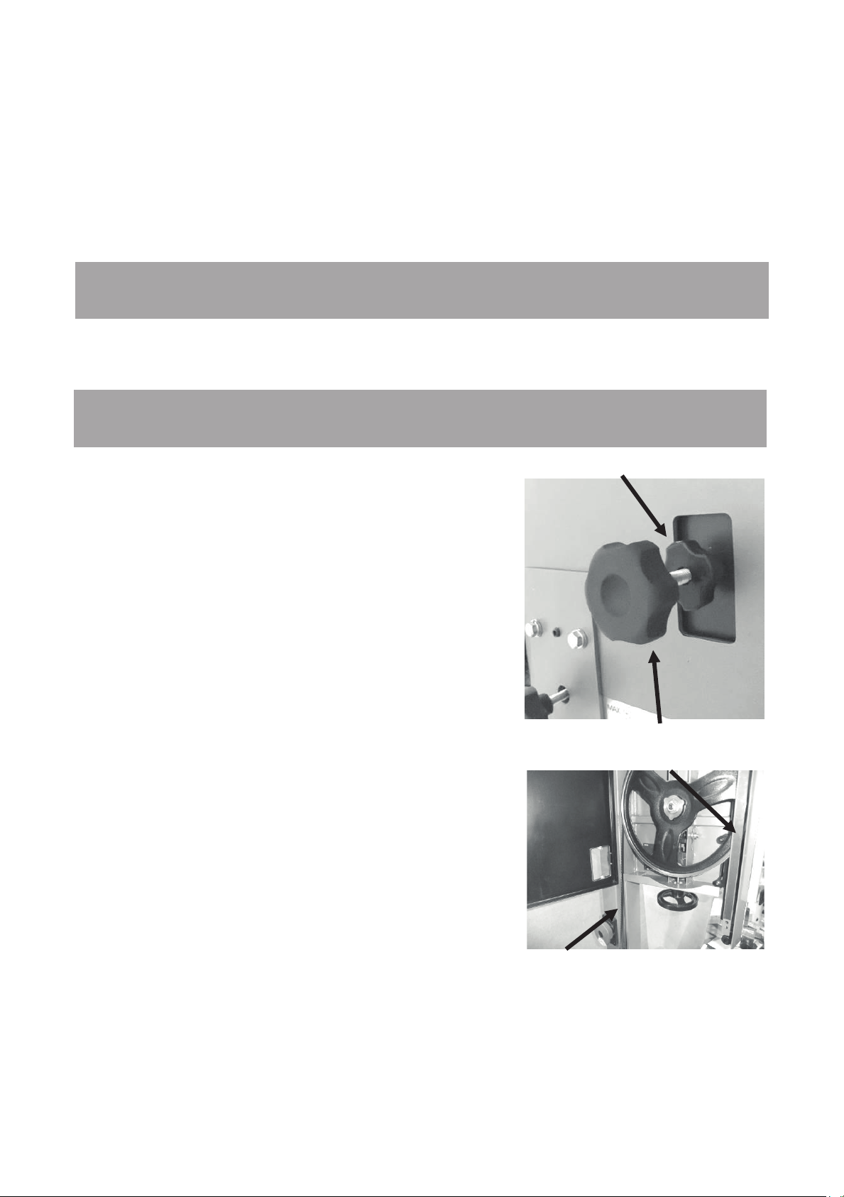
8. Open the blade guard door. Slide the blade over the top flywheel and feed through the slot
at the side of the vertical column. Then feed the blade into the blade guard slot and close the
blade guard door.
9. Deactivate the quick action blade tension lever and rotate the blade tension wheel so that
the blade can fit over the lower flywheel.
10. Activate the quick action blade tension lever.
11. Apply light tension to the blade with the blade tension wheel.
Tracking the blade.
Lock knob
Tracking knob
Blade guard door
Blade in column slot
8. Open the blade guard door. Slide the blade over the top flywheel and feed through the slot
at the side of the vertical column. Then feed the blade into the blade guard slot and close the
blade guard door.
9. Deactivate the quick action blade tension lever and rotate the blade tension wheel so that
the blade can fit over the lower flywheel.
10. Activate the quick action blade tension lever.
11. Apply light tension to the blade with the blade tension wheel.
Tracking the blade.
N.B. When tracking a blade the wheels will be stiff to turn, this is normal, the drive belt
can be released to aid the turning of the wheels if needed.
There are different opinions
should be on the wheels. One group of people
recommends that with large blades you should track the
blade so that the teeth hang just over the front edge of the
rubber. The second group recommends that all blades,
regardless of their size, should run in the center of the
wheel. The advantage of running the large blades with the
teeth not contacting the rubber of the wheel is that they
cannot damage the tire. The disadvantage is that the
wheel is crowned and the blade is not tensioned in the
center of the band, which gives the blade a tendency to
wobble or flutter. The advantage of running large blades
on the center of the wheels is that they are tensioned in
the center of the band and have fewer tendencies to
wobble and flutter. The disadvantage is that blades with a
large set on the teeth have a tendency to damage the
rubber of the tire. This does not have a great effect on the
performance of the bandsaw, as all blades are running on
the center section of the tire, which is not affected. We
recommend that you balance all blades on the center of
the wheels for optimum performance and a smoother cut.
1. To track the blade, start rotating the wheels by hand in
the normal direction. As you do this, watch the blade to
determine where the blade wants to track. If the blade is
tracking too far forward or backward, make small
adjustments with the tracking adjustment knob located at
the back of the bandsaw while still rotating the wheel.
Once the blade is tracking in the correct position, fully tension the blade and re-track. Lock the
tracking adjustment handle.
Tracking position of the blade on the wheels.
on the position that the blade
26
Page 27
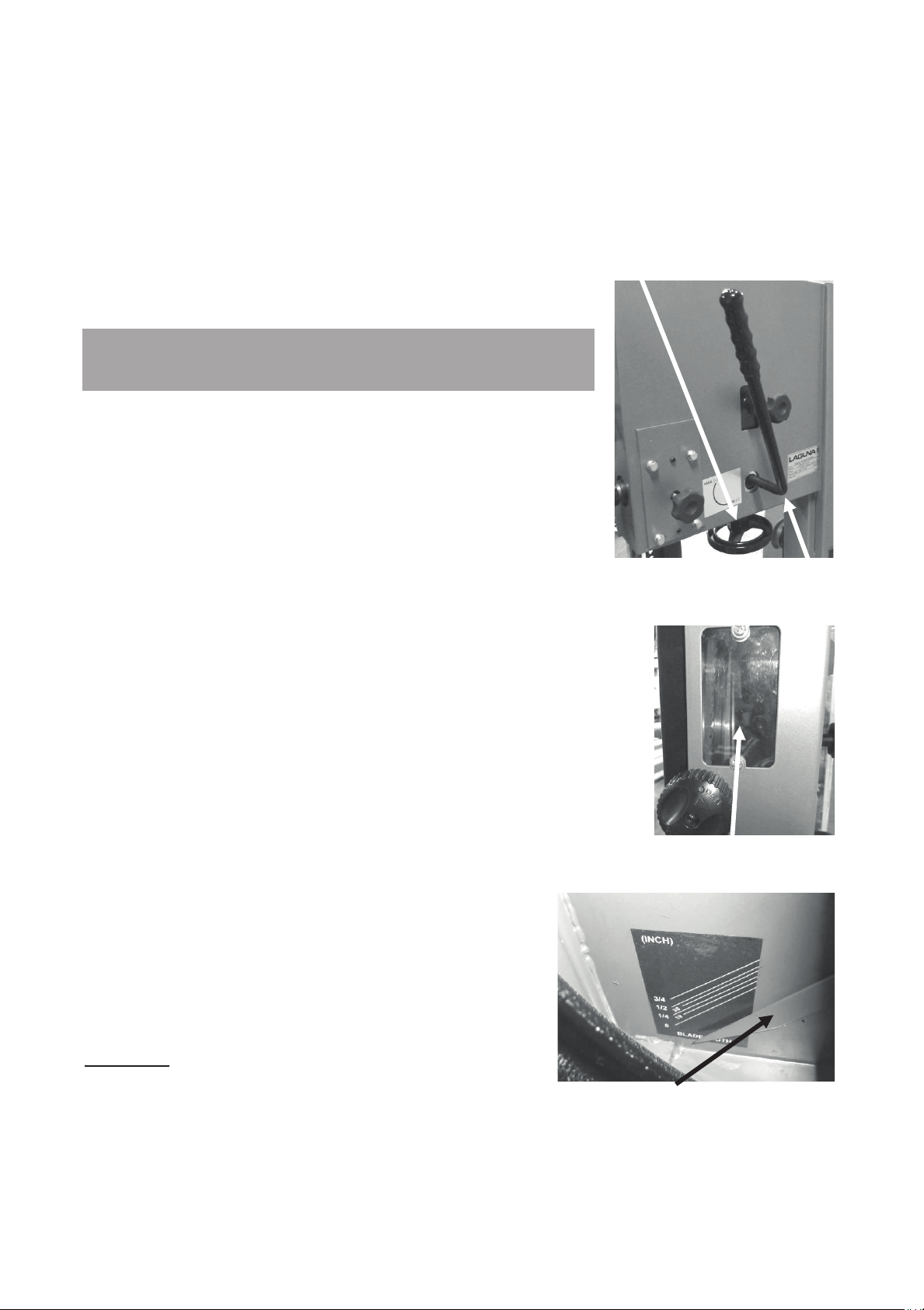
Blade tension wheel
tension lever (activated)
window
Blade tension indicator
Note. Tensioning the blade is covered later in the manual.
2. Refit the plastic blanking block.
Note: The blade must be fully tensioned for final tracking.
Note: Never track the blade with the saw running.
Note. There is a window on the side of the bandsaw that
allows the blade on the upper flywheel to be viewed. This will
assist you while you are tracking the blade.
Tensioning the blade.
There are a lot of opinions on how to tension a blade and if you
should buy a blade tension gauge. Before you purchase a
blade tension gauge, note the following points:
Most blade tension gauges are fitted to the blade and measure
the amount the blade stretches when you tension it. Each
blade manufacturer uses a different type of steel with different
tensile strength. This means that each type of steel has a
different rate of stretch. For example, if you buy a tension
gauge from one blade manufacturer, it is designed for use on
their blades, or range of blades, and will not necessarily give
you accurate readings in lbs/square inch on another manufacturer’s
blades because their blades stretch at a different rate. In reality,
there is nothing quite as quick or as accurate as experience.
Your machine is fitted with a blade tension indicator, which
measures the deflection of the tension spring on the upper flywheel.
We recommend that you use it only as a general guide and use one
of the following tensioning procedures to tension the blade.
Quick action blade
Method 1.
Looking at the top wheel, place your finger at the 9 o'clock position.
Move your finger down 6", and, using moderate pressure with your
thumb, press on the flat of the blade. You should get 3/16" to 1/4" of
deflection. Refit all the guards and close the doors. Replace the
table insert and check that the blade moves freely
through the table insert. Check that all wrenches and
loose parts are removed from the machine.
Plug the machine into the power. Turn the machine on
for a second and switch off. Watch how the blade runs.
If the blade tracks well, then run the machine at full
power. If the blade tracking needs adjustment, repeat
adjustment.
Method 2.
Tension the blade as described in method 1.
Blade tracking
30
27
Page 28

Close all the doors and ensure that all the guards are fitted.
Start the band saw and look at the blade from the front of the machine. Start to detension the
blade very slowly until the blade starts to flutter (wobble from side to side). Then start to
tension the blade until the blade stops fluttering and is running true. Increase the tension on
the blade by one complete turn on the tension handle. You may find that each size and type of
blade will need more or less additional tension. For example, a 1/16" blade will need less
additional tension than a 3/4" blade. Again, experience is the key, and with a little practice it
will become second nature.
The key to all tensioning is to get the blade to cut straight and true with the minimum amount
of tension. The less tension that you put on the blade, the longer the blade and the machine
will last.
Note. The upper flywheel has a spring that is used to keep a constant pressure on the blade
during use. As the blade cuts, heat is generated, which causes the blade length to expand.
The spring compensates for the change in length, and you must never bottom out the spring
while tensioning the blade.
Note. If you are not using the bandsaw for extended periods of time (overnight), remove the
tension on the blade. This will increase the life of your blade and the machine. If tension is left
on the machine, flats or grooves can be formed in the rubber of the wheels, which will detract
from the performance of the machine and in extreme cases cause vibration. Removing the
tension will greatly enhance the life of the machine, bearings and tires.
Label the machine “detensioned.” On the label, mark the number of turns that you
detensioned; this way you will know how many turns that you have to put back on to have
your blade correctly tensioned.
Removing the blade from the bandsaw.
1. Disconnect the power to the bandsaw.
2. Remove the table split clamp that aligns the two table halves.
3. Remove all the guards.
4. Remove the table insert.
5. Remove the tension on the upper flywheel.
6. Open the doors and remove the blade from the wheels (use gloves and eye protection) and
gently slide the blade through the table slot.
Adjusting the blade guards.
Introduction.
Welcome to a new era in bandsawing. You have purchased a bandsaw with a revolutionary
blade guide system that is designed to give you years of safe, high-quality bandsawing. Most
blade guides are designed to support the blade on the sides and either above or below the
side guides at the back of the blade. This can allow the blade to twist as pressure from the
wood being cut pushes against the back blade guide. The Laguna Guide eliminates this by
31
28
Page 29

supporting the blade above and below the back blade guide, giving the blade unsurpassed
stability. The Laguna Guide also incorporates patented ceramic as the blade support material.
The advantage of this material is its ability to resist wear, and with care it should give years of
safe service.
Please read the following notes as they will assist you in getting the optimum
performance from your Laguna guide system.
As with the roller guide systems, the Laguna guide system will damage your blade if it is not
adjusted correctly. The guide blocks must not come in contact with the teeth of the blade. It is
advisable to run the blade by hand with the guide blocks completely clear of the blade, and
only when you are completely sure that the blade is running consistently in the correct
position, you may then adjust the surround guide blocks as detailed in this manual.
Note on using the Laguna ceramic guide system.
1. When fitting a blade to your bandsaw, adjust the guide blocks as detailed later and run the
blade by hand through the guide blocks for at least two complete revolutions.
2. The weld on a new blade may not be perfectly aligned, and the misalignment could hit the
ceramic blocks (side and back), causing damage to the blocks or the blade. If the blade has a
bad weld, return it to your blade supplier or side dress and file the back of the blade as
needed.
3. The back blade guide is manufactured from ceramic, so as the blade pushes against it,
friction between the blade and the ceramic occurs. This action generates a certain amount of
sparks. This is normal and will become less with time as the back of the blade guide
smoothes out the back of the blade.
4. The back blade guide will slowly form a small grove as the blade is used (this is normal). It
is recommended that for approximately every 8 hours of use, the guide be rotated 15
degrees. This will ensure that the groove does not become too deep and will greatly extend
the life of your guide.
5. The 14-12 Laguna guide system can be used with 1/8" to 3/4" blades.
6. The Laguna guide system uses ceramic to support and guide the blade. This has many
advantages (very poor conductor of heat, very resistant to wear, etc.). The disadvantage is
that it is very brittle, so the guides must never be dropped, exposed to hard knocks, hit with
hard objects or used with badly welded blades. Any of the above actions may cause the
ceramic to chip or break and will detract from the performance of the Laguna guide system.
Any mistreatment of the guide system will render the warranty void.
7. The side guide blocks must be tightened before running the machine to avoid jamming the
blade and damaging the machine and/or guide blocks.
8. When cutting gummy or green wood, the blade can become covered with resin. You will
find that the surround guide system ceramic blocks remove the resin as the blade is moved
through the guide blocks and keep that part of the blade clean. For this reason it is
recommended that the blocks be adjusted as close to the gullet as possible, but the teeth
must not come in contact with the blocks, as they will become damaged. Although the guide
blocks clean the blade, some woods will still gum the blade and the resin will have to be
removed with solvent.
32
29
Page 30
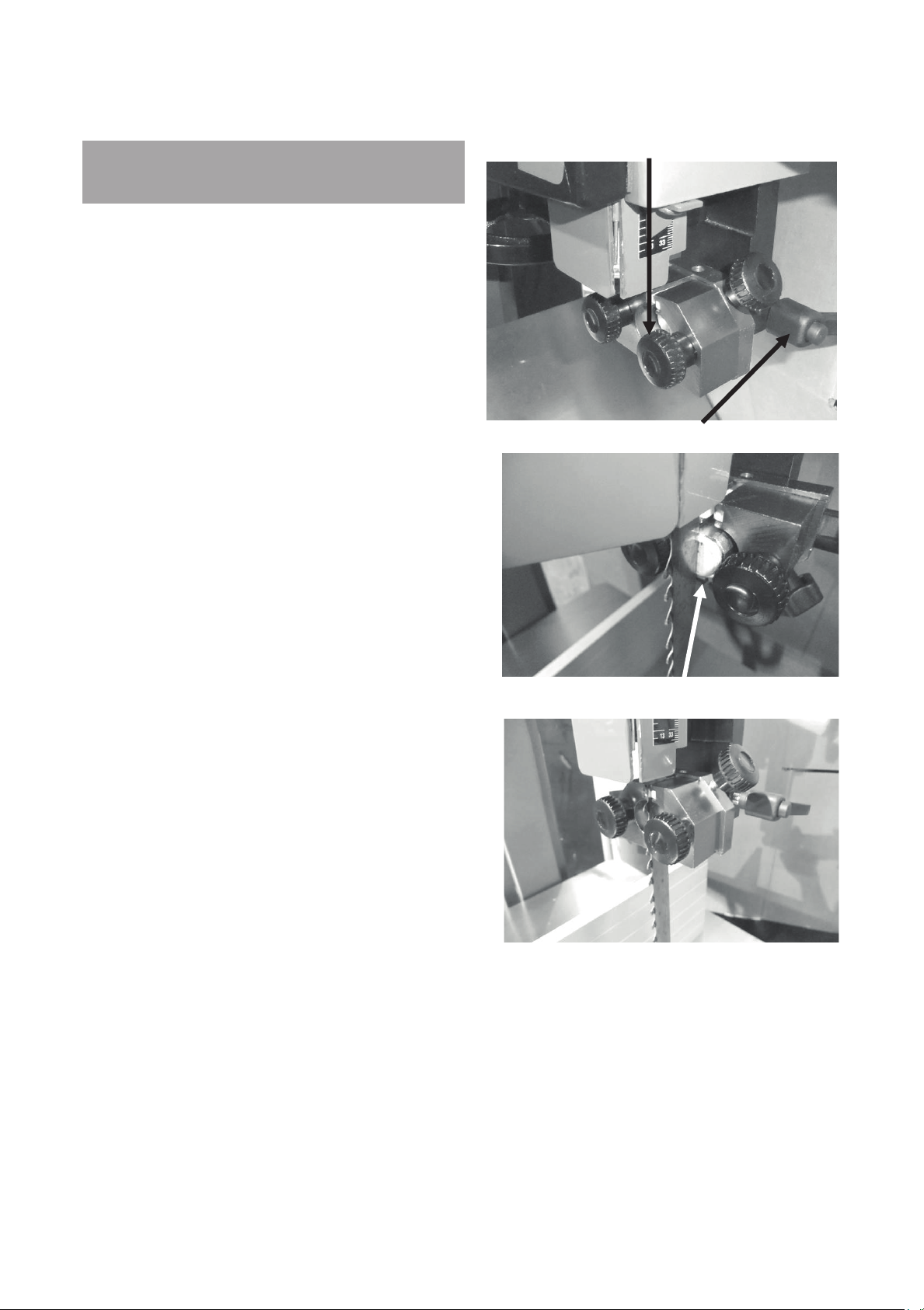
Side guide clamp screw
Back guide clamp screw
blade
Adjusted guide
Adjusting the blade guides.
The blade should run through the center of
the rear blade guide, and the side guides
should be parallel with the blade. If they have
been moved out of adjustment, adjust as
follows:
Top Upper Side Guides Parallel
Adjustment.
Loosen the side guides and move out as far as
possible. Loosen the guide assembly and
move back away from the blade.
Move the back blade guide forward so it just
touches the back of the blade and lock in
position.
Loosen the guide clamp screw that allows the
side guides to move forward and back. Adjust so
that the ceramic blocks are just behind the gullet
of the teeth and are parallel to the blade.
Retighten the clamp screws.
Gently push one side guide so that it touches the
blade and lock it in position. Bring the other
guide toward the blade so that there is minimal
clearance between the blade and the guide. You
can put a thin piece of paper to put between the
blade and the guide to obtain the correct
clearance until you gain experience. Tighten the
clamp screws and remove the paper. Rotate the
blade by hand, ensuring that the weld of the
blade does not hit the ceramic blocks, as this will
cause damage. If the blade has a bad weld,
dress the blade or return it to your supplier.
Rotate the blade by hand and check that the
back of the blade does not hit the blade guide
with a bad weld. If the back of the blade hits the
back blade guide at the weld, then dress the
blade or, in excessive cases, return the blade to
the supplier.
Back guide touching the back of the
33
30
Page 31
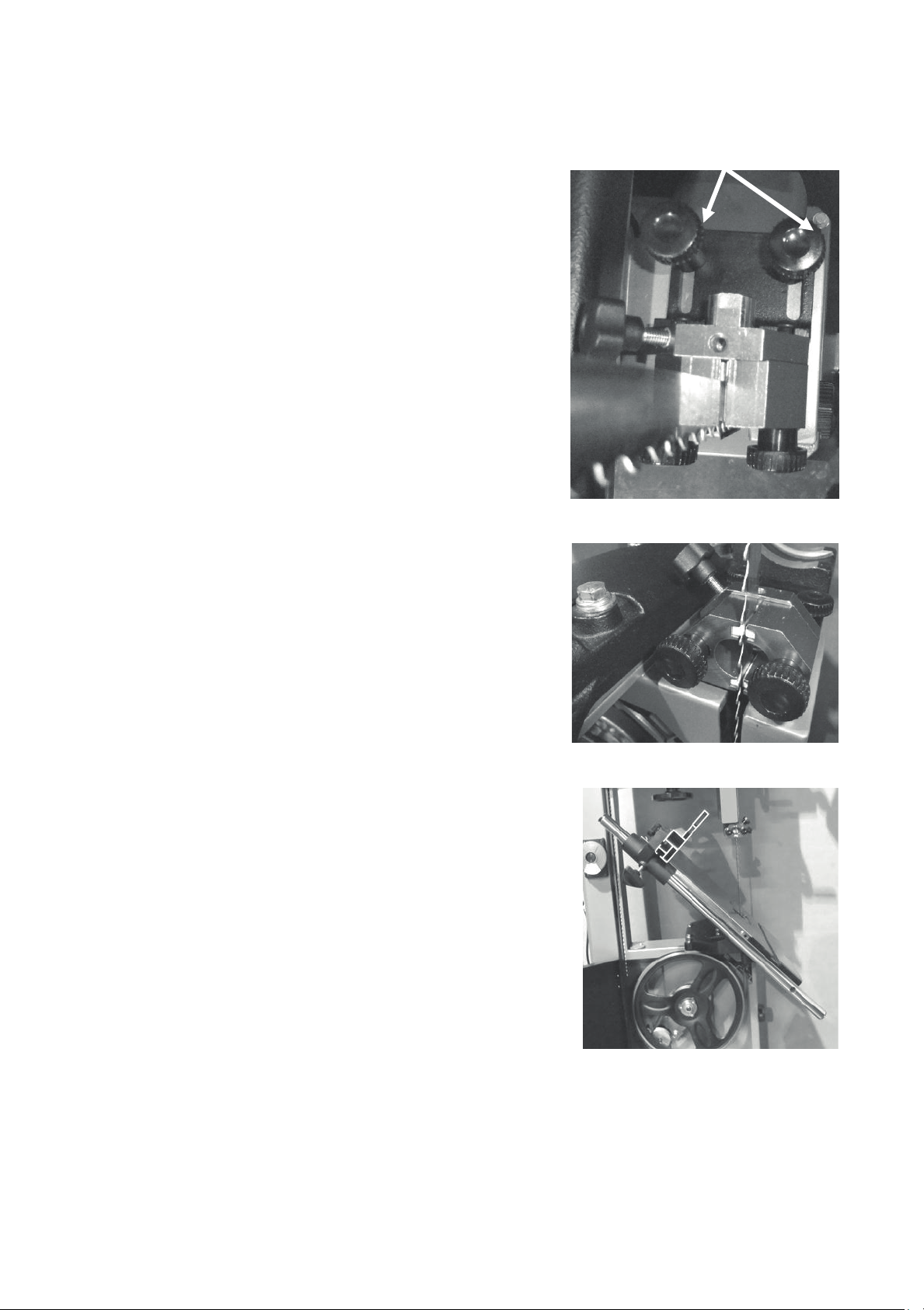
Guide locking screws
the table removed for clarity
ceramic just behind the gullet
Table adjusted to 45 degrees
Lower blade guide.
The lower blade guides have two locking screws that,
when released, allow the guide assembly to be moved
forward and back. Rotate the blade by hand and ensure
that it is tracking consistently in the correct position.
Loosen the side guides and move out from the blade.
Loosen the two clamp screws that allow the guide
assembly to move forward and back. Adjust it so that the
ceramic blocks are just behind the gullet of the blade and
retighten the clamp screws.
Place a dollar bill or piece of paper of similar thickness
between the guide blocks and the blade. Gently bring
both side guides toward the blade so that slight pressure
is exerted on the blade. Tighten the clamp screws and
remove the paper. Rotate the blade by hand, ensuring
that the weld of the blade does not hit the ceramic blocks,
as this will cause damage. If the blade has a bad weld,
dress the blade or return it to your supplier.
Loosen the rear guide clamp screw and push the guide
forward so that it just touches the back of the blade.
Tighten the guide in position.
Rotate the blade by hand and check to see that the
back of the blade does not hit the blade guide with a
bad weld. If the back of the blade hits the rear blade
guide at the weld, then dress the blade or, in excessive
cases, return the blade to the supplier.
Note: You will probably find that the guides can be
adjusted more easily by tilting the table to 45 degrees.
Note: Rotate the back guide by approximately 15
degrees after every 8 hours of use. This will greatly
extend the life of the back blade guide, as it will even out
the wear.
Before you cut any wood, read the safety rules at the
front of this manual.
Lower blade guide shown with
Side guides adjusted with
34
31
Page 32
Using the bandsaw.
lthough the bandsaw is usually associated with cutting curves, a variety of straight cuts are
A
easily made with the saw. In fact, it is often used to rip wood because it is much safer than a
radial arm saw and also has a smaller saw cut, so it wastes less wood. This becomes very
important when using expensive wood where waste must be kept to a minimum. The cut is
safer because the force of the cut is straight down on the table; the work cannot be pulled
back or kicked back, which sometimes happens with table or radial arm saws. The bandsaw
can also cut very thick stock, which the radial arm, or table saw cannot do. The disadvantage
of cutting with the bandsaw is that the surface finish of the cut is not as good as with the table
or radial arm saw. This can be overcome to a great degree by using the Resaw king blade
from Laguna. The blade has many of advantages such as superior surface finish to the cut,
thin kerf (low wood waste), it can be re-sharpened, will cut hard woods and has a long life.
Ripping.
Ripping is a cut made with the grain of the wood. The four most common cuts made with the
grain of the wood are rip, bevel, taper and resaw cuts. There are two frequently used
techniques for making straight bandsaw cuts. One technique is to use a single point to guide
the work. The rationale for using a single point is that the saw may tend to cut at a slight
angle. This is called drift or lead. The single point allows the operator to compensate for the
drift and cut the wood straight. With a little practice, you will obtain satisfactory results using
this method. However, you now own a real bandsaw, so this method is not recommended.
Another method is to use the rip fence as a guide. Once set up, this takes the guesswork out
of cutting, reduces the stress on the operator and is a must for volume work. Once you have
mastered the setup procedure, you will tend to use the single point method less and less.
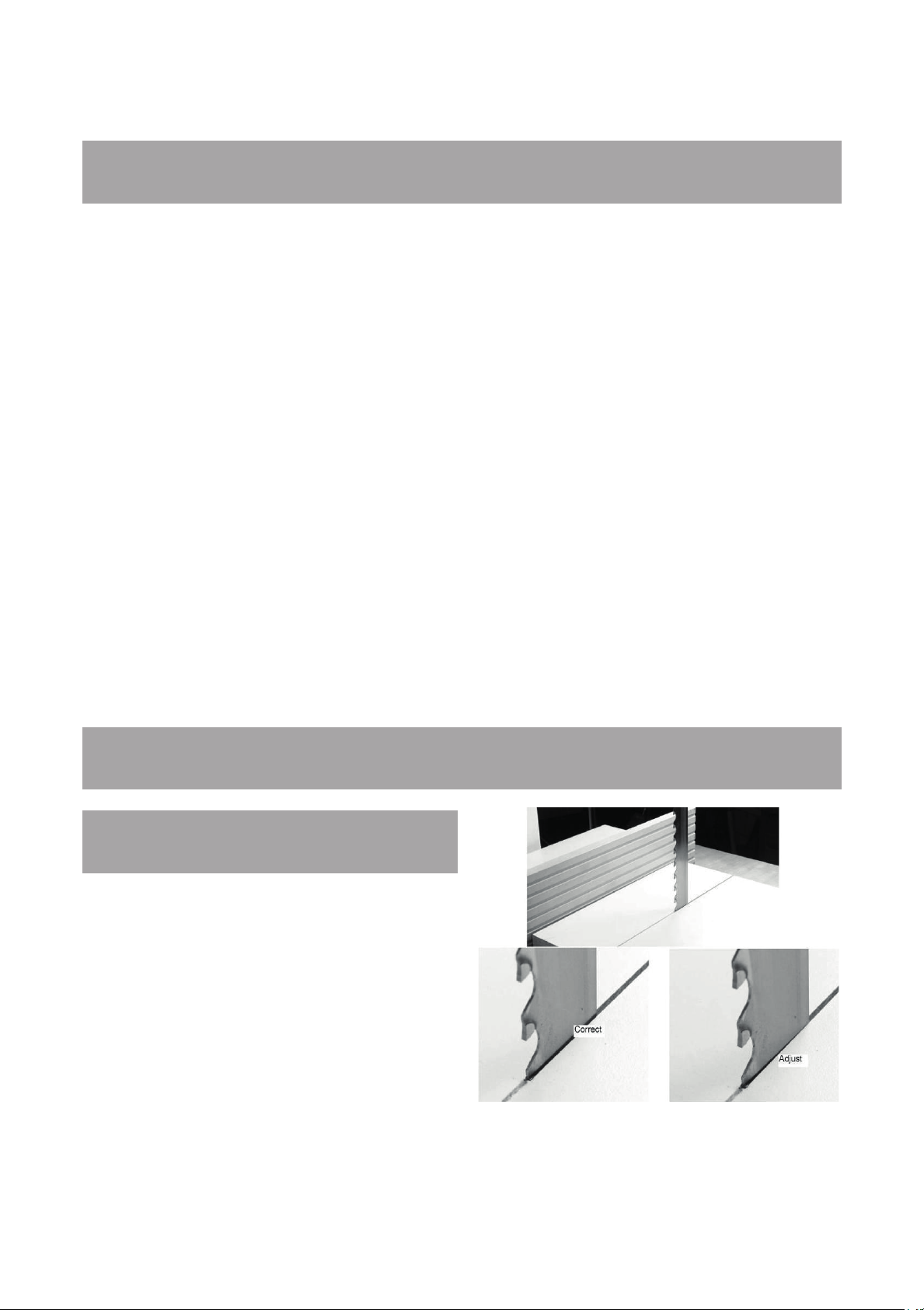
Adjusting the fence for drift.
Method 1.
1.
Make a straight pencil line on the edge of
board.
2. Feed the wood into the blade cutting next
to the pencil mark. If the blade is drifting, yo
ill have to compensate by angling the wood
w
to keep the cut straight.
3. Stop the cut in the middle of the wood an
m
ark (with pencil) the angle on the table. Thi
a
u
d
s
35
32
Page 33

is the angle of drift, and you will have to set the fence to the pencil line.
4. To adjust the fence, loosen the clamp bolts that attach it to the cast bracket. Move the
f
ence so that it lines up with the pencil mark on the table and retighten the clamp screws.
Method 2.
1.
Set the fence parallel with the blade by loosening the clamp screws that hold it to the cast
bracket. It is not important that it is exact because you will be readjusting later in the
procedure.
2. Using a piece of scrap wood, make a cut while holding the wood against the fence. Sto
he cut in the middle of the wood.
t
3. Look at the position of the back of the blade within the saw cut. The back of the blade
should be in the center of the slot, but you will probably find that it is closer to one side.
4. Slightly loosen the clamp screws and adjust the fence to compensate.
Repeat steps 2, 3 and 4 until the blade is centered
N
ote: You may have to do several fine adjustments, and it is better to do several smal
ustments until you become skilled at the procedure. Once you have mastered the process,
adj
it should only take a minute to perform the adjustment.
Note: Each blade has a slightly different drift, and each time you change a blade, you must
check and readjust if necessary.
N
ote: It is worth taking the time to set the fence accurately as it will save frustration and
enhance the performance of your machine.
.
p
l
Adjusting the table rule.
There is a rule that is fitted to the side of the table and can be used as a quick guide on the
distance that the fence is from the blade.
Note. The rule will have to be adjusted each time the fence is adjusted for drift, as this will
change the distance the fence is from the blade.
Once the fence has been adjusted for drift:
1. Lock the fence to the rail.
2. Measure the distance from the front of the blade to the fence.
3. Check the distance indicated on the rule.
4. Loosen the clamp bolts and adjust the rule.
5. Tighten the clamp bolts and recheck.
33
36
Page 34
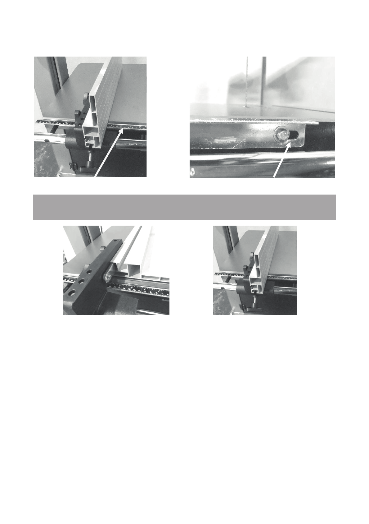
Table rule
Adjustment slot
Fence in low position
Fence in high position
Fence position.
The aluminum fence can be used in two height positions (high and low). The low position is
handy for cutting thin wood and is used where the fence in the high position would make it
awkward to complete cuts. The fence in the high position is used for supporting tall work.
Changing the fence height.
1. Loosen the clamp screws that are located on the cast bracket.
2. Slide the aluminum fence off the cast iron bracket.
3. Slide the aluminum fence back onto the bracket using the second slot and retighten the
clamp screws.
37
34
Page 35

Resawing.
Resawing is the process of cutting a board in half along its height. The bandsaw is perhaps
the most creative tool in the shop because of its ability to cut thick or thin, straight or curved.
The ability to cut thick stock such as re-sawing, making veneers, book matching or cutting
flitches from small logs has great appeal to the woodworker. These capabilities greatly
enhance the woodworker’s design ability without the need for additional equipment. When a
board is resawed and the two pieces are lying next to each other, you will note that they are
mirror images of each other. When these two boards are glued together, it is called bookmatching.
Note: It is unsafe to cut wood that is unsupported by the table and should never
be attempted. This is especially important to note when cutting round logs.
Blades.
Introduction.
The selection and use of blades is a very extensive subject, and there have been many
books written on it. This section of the manual is intended as a general guide only.
Selecting a blade.
Using the correct blade is important, as it is the first step in attaining good bandsaw
performance. The most frequently asked question is "How do I decide on the correct blade to
use?" The answer is not simple, and we will explore it in this section of the manual. Firstly,
there is NO ideal blade that will do everything. The blades that you choose will be determined
by the type of work that you are doing. Large-tooth wide blades are selected for fast course
cuts, and fine, thin blades are used for intricate scrollwork. You will find that you will need a
large selection of blades if you do a lot of varied work and fewer blades if you are
concentrating on one section of bandsawing such as re-sawing. Using the wrong blade is the
best way to abuse it. Using a blade for its intended purpose allows for maximum efficiency
and is the best way to prolong its life.
Blade terms.
Set.
The amount that the teeth are wider than the thickness of the backing material. The larger the
set, the larger the saw cut and the smaller the radius that can be cut. This can also be an
38
35
Page 36

advantage if you are cutting a job that has a tendency to nip the blade. The smaller the set,
the smaller the saw cut and the larger the radius that can be cut; the wood waste is less. On
tipped blades (Resaw King) there is no set, as the tip is wider than the backing material.
Thickness.
The thicker the blade, the stiffer the blade and the straighter the cut. The thicker the
band, the greater the tendency for the blade to break.
Pitch.
The size of the teeth. This is usually quoted in teeth per inch (TPI). The larger the tooth, the
faster the cut because the tooth has a large gullet and has a greater capacity to transport
large amounts of sawdust through the job. The larger the tooth, the coarser the cut and the
poorer the surface finish of the cut. The smaller the tooth, the slower the cut as the tooth has
a small gullet and cannot transport large amounts of sawdust through the job. The smaller the
tooth, the finer the cut and the better the surface finish of the cut
Material Hardness.
When choosing the blade with the proper pitch, one factor you should consider is the
hardness of the material that is being cut: the harder the material, the finer the pitch that is
required. For example, exotic hardwoods such as ebony and rosewood require blades with a
finer pitch than American hardwoods such as oak or maple. Soft wood such as pine will
quickly clog the blade, decreasing its ability to cut. Having a variety of tooth configurations in
the same width will most likely give you an acceptable choice for a particular job. There are
certain things that indicate if a blade has a proper pitch, too fine a pitch or too coarse a pitch.
Some are listed below:
Proper Pitch.
Blades cut quickly.
A minimum amount of heat is created when the blade cuts.
Minimum feeding pressure is required.
Minimum horsepower is required.
The blade makes quality cuts for a long period.
Pitch Is Too Fine.
The blade cuts slowly.
There is excessive heat, which causes premature breakage or rapid dulling.
Unnecessarily high feeding pressure is required.
Unnecessarily high horsepower is required.
The blade wears excessively.
Pitch Is Too Coarse.
The blade has a short cutting life.
The teeth wear excessively.
The bandsaw vibrates.
36
39
Page 37

Width.
The dimension from the back of the blade to the front of the teeth. The wider the blade, the
stiffer the blade and the straighter the cut. This is usually called beam strength. But wide
blades cannot cut small radiuses.
The narrower the blade, the more flexible the blade and the greater the tendency the blade
has to wander. These have low-beam strength, but can cut small radiuses. Blades are
available from 1/8" up for your machine.
Kerf.
The width of the saw cut. The larger the kerf, the smaller the radius that can be cut, the
greater the amount of wood the blade has to be removed by the blade and the greater the
horse power that is needed because the blade is doing more work. The greater the kerf, the
larger the amount of wood that is being wasted by the cut.
Hook or Rake.
The cutting angle or shape of the tooth. The greater the angle, the more aggressive the tooth
and the faster the cut. But the faster the cut, the faster the tooth will blunt, and the poorer will
be the surface finish the cut will have. Aggressive blades are suitable for soft woods but will
not last when cutting hard woods. The smaller the angle, the less aggressive the tooth, the
slower the cut and the harder must be the wood that the blade is suitable to cut. Hook teeth
have a progressive cutting angle and take the form of a progressive radius. They are used for
fast cutting where finish is not important. Rake teeth have a flat cutting angle and are used for
a fine surface finish of the cut.
Gullet.
The area in which the sawdust has to be transported through the wood, the larger the
tooth (pitch) the bigger the gullet is.
Relief.
The angle from the tip of the tooth back. The greater the angle, the more aggressive
the tooth but the weaker the tooth.
Beam Strength.
This is the ability of the blade to resist bending backwards. The wider the blade, the stronger
the beam strength; therefore, a 1" blade has far greater beam strength than a 1/8" blade and
will cut straighter and is more suitable for resawing.
Blade Selection.
As you have seen from the previous section, there are a great number of variables. The blade
selection that you will make will greatly depend on the type of work that you intend to do with
your machine. If you have experience with the bandsaw, you will probably have a good idea
of the blades that are suitable for you. If you lack the experience or are unsure of the type of
work you will be doing with your machine, we recommend that you purchase a selection
similar to that listed below, which is a good general selection and will allow you to tackle most
jobs. As you gain experience, you will settle on the blades that suit you.
40
37
Page 38

1. 1/4" 6 TPI. This is a small, aggressive blade that is suitable for tight curves and fast cutting
where a good surface finish of the cut is not important.
2. 1/4" 14 TPI. This is a small, fine blade suitable for reasonably tight cuts where the surface
finish is important but speed of cut is less important.
3. 1/2" 3 TPI. This is a general-purpose blade that can cut large radiuses and short sections
of straight cuts. The cut is fast but the surface finish of the cut is poor.
4. 3/4" 3 TPI. This is a general-purpose blade, which will be used for straight cuts and is
suitable for large radiuses.
Rounding the back of the blade.
With most guide systems it is recommended that the back of the blade be rounded with a
stone. As the machine is supplied with Laguna ceramic guides, this is not imperative because
the ceramic will round the back of the blade as it is used. However, if you decide that you
want to round the back of the blade, a procedure follows.
A round blade back creates smooth interaction between the thrust bearing and the blade. If
the blade rotates slightly, there is no sharp blade corner to dig into the thrust bearing; also,
the rounding process smoothes the weld. A blade with a round back makes tight turns better
because the round back has smooth interaction with saw kerfs.
After the guides have been adjusted and the machine is running, hold the stone against the
back corner of the blade for about a minute. Wear safety glasses when rounding the blade.
Then, do the same thing on the opposite corner. Next, slowly move the stone to round the
back. The more pressure you put on the back, the faster you will remove the metal. Be careful
that the inside of the machine is free of sawdust because sparks could start a fire. On small
blades such as a 1/4" blade, the pressure on the back of the blade may bring the blade
forward off the front of the wheels. Therefore, be careful not to put too much pressure on the
stone. When doing this, it is also important that the upper guides be positioned right above
the stone.
The blade has teeth and extreme caution must be exercised, as your hands will
be very close to them.
Causes of blade breakage.
1. Excessive blade thickness in relation to the flywheel diameter.
2. Defective welding.
3. Incorrect tension, particularly if the blade is over tensioned; the tension spring no longer
fulfils its function.
38
41
Page 39
4. After use it is recommended that you slacken the tension, especially overnight. (Be sure to
place a clearly visible note on the machine that you have done this.
5. Misalignment of the flywheels.
6. Irregularity of flywheel surface, for instance, an accumulation of sawdust while cutti
r
esinous materials.
You can correct these problems by readjusting the machine, changing the way you operate it
or by changing the blade. Try only one change at a time
Causes of blade dulling.
1.
Poorly set side guides or rear thrust guide.
2. Poor tracking
Wrong blade selection. If the blade is too narrow, it will flex more easily and decrease the
3.
quality of the cut. The blade should also have the correct pitch and width
4. The tooth pitch is too fine (too many teeth per inch).
5. Certain woods will dull a steel blade very quickly, especially tropical hardwoods (teak, koa
tc.). Other woods with a high silicon content will also dull the blade quickly; even a cut a
e
s
hort as 6” will cause damage to the blade.
6. On certain exotic woods, the ends have been painted. This is done to control the drying.
The paint is very abrasive and will dull the blade as you cut through it. It is recommended that
you cut the painted ends off your wood
.
.
.
.
ng
s
,
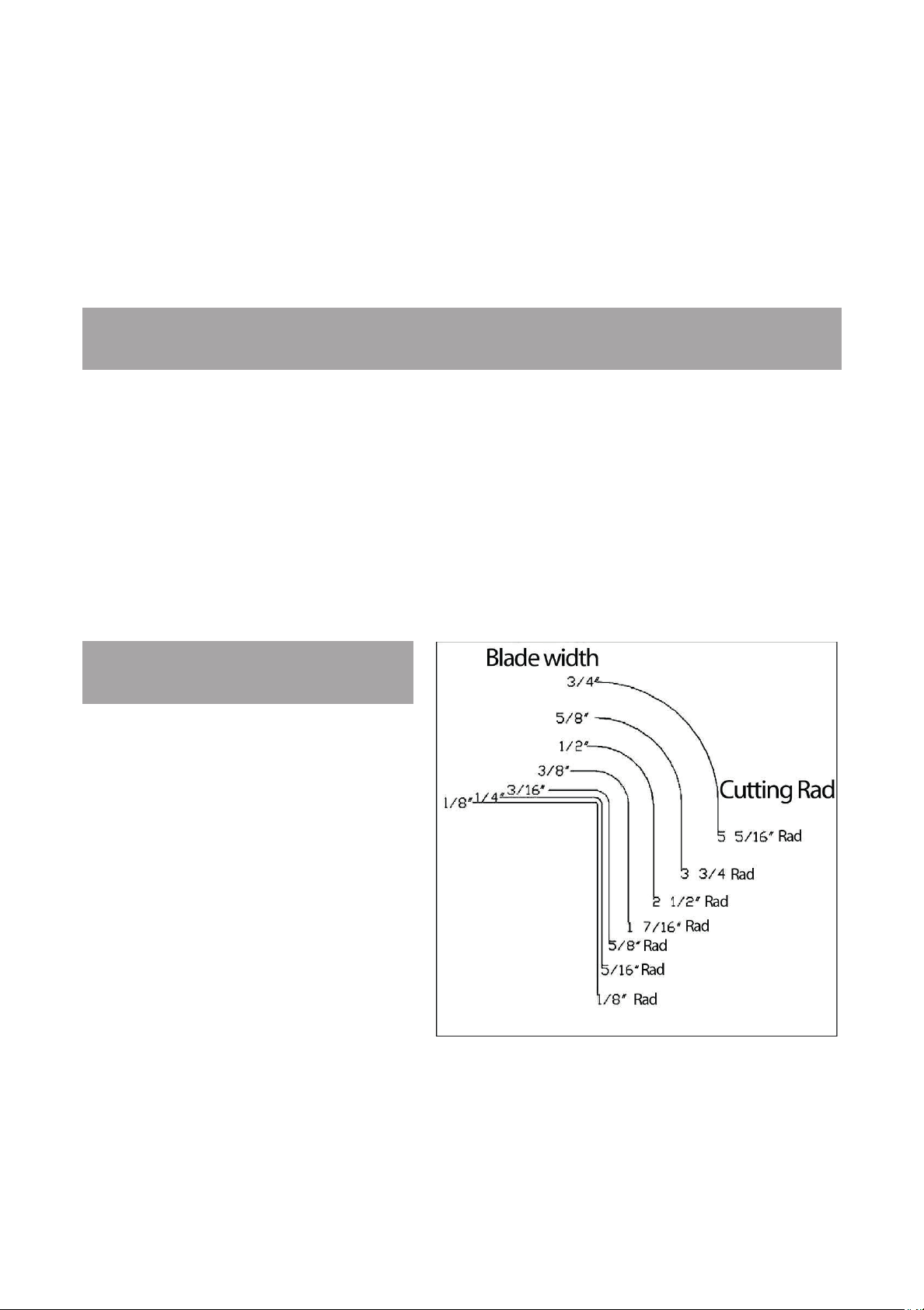
Using a radius chart.
Unt
il you become well acquainted with
your saw, it is best to use the contour
(radius) chart to determine which size
blade to use for a specific application.
Radius charts can be found in many
woodworking books, magazine articles
and on blade boxes. They differ slightly
from one another but are good as rough
indicators of how tightly a curve can be
cut with a particular blade. Each blade
saw and operator is different, so it is
impossible to make a truly accurate
chart. A blade can cut continuously
without backtracking any curve that has
a radius as much as or more than is
shown on the chart. For example: a
3/16" blade will cut a circle with a 5/16" radius or a 5/8" diameter. To test if a 3/16" blade
39
42
Page 40

would work for a particular curve, place a dime (roughly 5/8") over the pattern. The 3/16"
blade can cut a curve bigger than the dime, but not smaller. You can use everyday items such
as coins or a pencil to determine which blade to use. A quarter is the size of the tightest cut
that can be made with a 1/4" blade. A dime is the size of the tightest curve that can be cut
with a 3/16" blade. A pencil eraser is the size of the tightest turn that you can make with a 1/8"
blade. After a while you won't even need an object to size the possible curve of a blade
because you will have become familiar with this process. There are options to matching the
blade to the smallest curve pattern. If there is only one very tight cut, it may be best to use a
turning hole, a relief cut, successive passes or to change the blade. If you have a lot of cutting
to do, you can use a wider blade for the bigger curves and then switch to a narrower blade for
the tighter curves. Changing the blades can often save cutting and finish time. The chart
above is only a rough guide and is not to scale, but from the information you can construct
your own guide.
How to coil a bandsaw blade.
Without a doubt it is more difficult to explain how to coil a bandsaw blade than it is to actually
do it. Nevertheless, below are easy-to-follow instructions on folding a blade.
Method One.
While wearing a jacket or long-sleeved shirt and gloves, hold the blade in front of you in one
large loop, with the teeth facing towards you. Place your foot on the blade, holding it on the
ground. Grasp the blade with both hands, with your thumbs to the outside, at approximately
the 10 o'clock and 2 o'clock positions (Step 1). Slowly twist the top of the blade away from
your body (Step 2). Bring your hands together to form two loops while folding down (Step 3).
Continue rotating the blade until you form three loops.
Note. It is recommended that the blade be placed on material that will not damage the blade
teeth (wood or cardboard). Your foot is there to give stability and not to clamp the blade, so
do not exert excessive force, or the teeth/band may be damaged. The photographs are
shown without gloves to enable the hand/thumb position to be shown. Gloves must be worn,
as the blade could cause injury.
43
40
Page 41
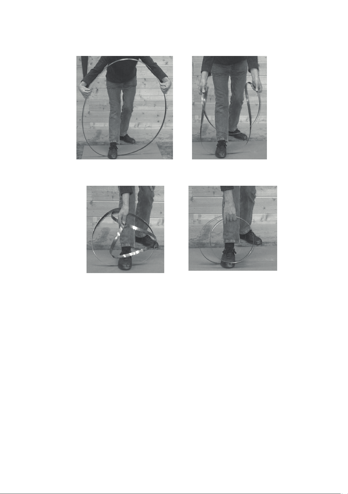
Step 1
Step 3
Step 2
Done
Note: In order to show the hand/thumb position of the man in the
photographs, he is not wearing gloves, but gloves MUST BE WORN
as the blade could cause injury.
44
41
Page 42
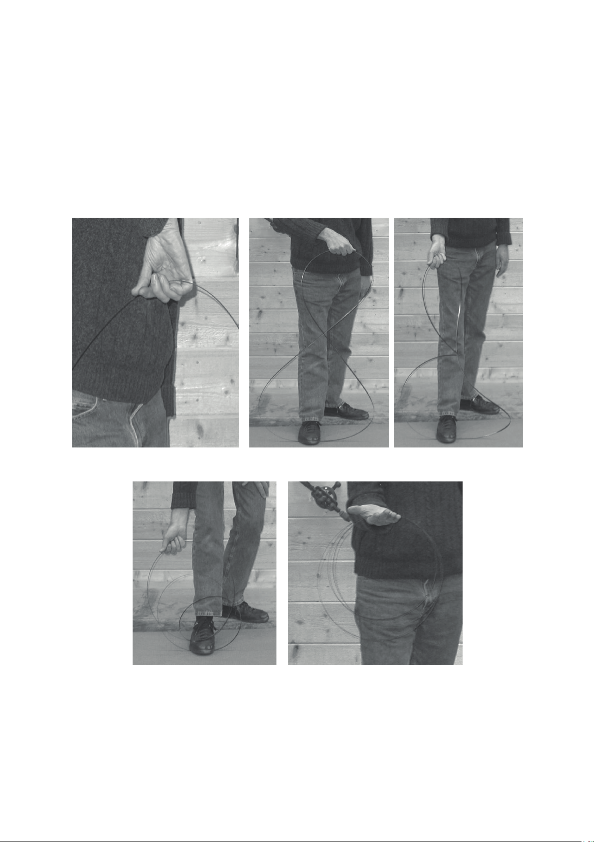
Method Two.
There is another variation of this that works well with small blades but simply is not
possible for larger bandsaw blades, unless you're very big and strong. This method works
the same as the method above, but rather than holding the blade with both hands, grasp
the blade at the top while holding the bottom of the blade with your foot (teeth still facing
away from you). Grasp the blade with your hand, twisting your arm such that your elbow is
facing away from your body (Step 1). Turn the palm of your hand toward your body about
180 degrees and then continue turning while pushing down on the blade (Steps 2, 3 and
4). The blade will fold down upon itself into three circles, lying flat on the ground (Done).
St
ep 1
Step 4
Step 2
Done
St
ep 3
45
42
Page 43
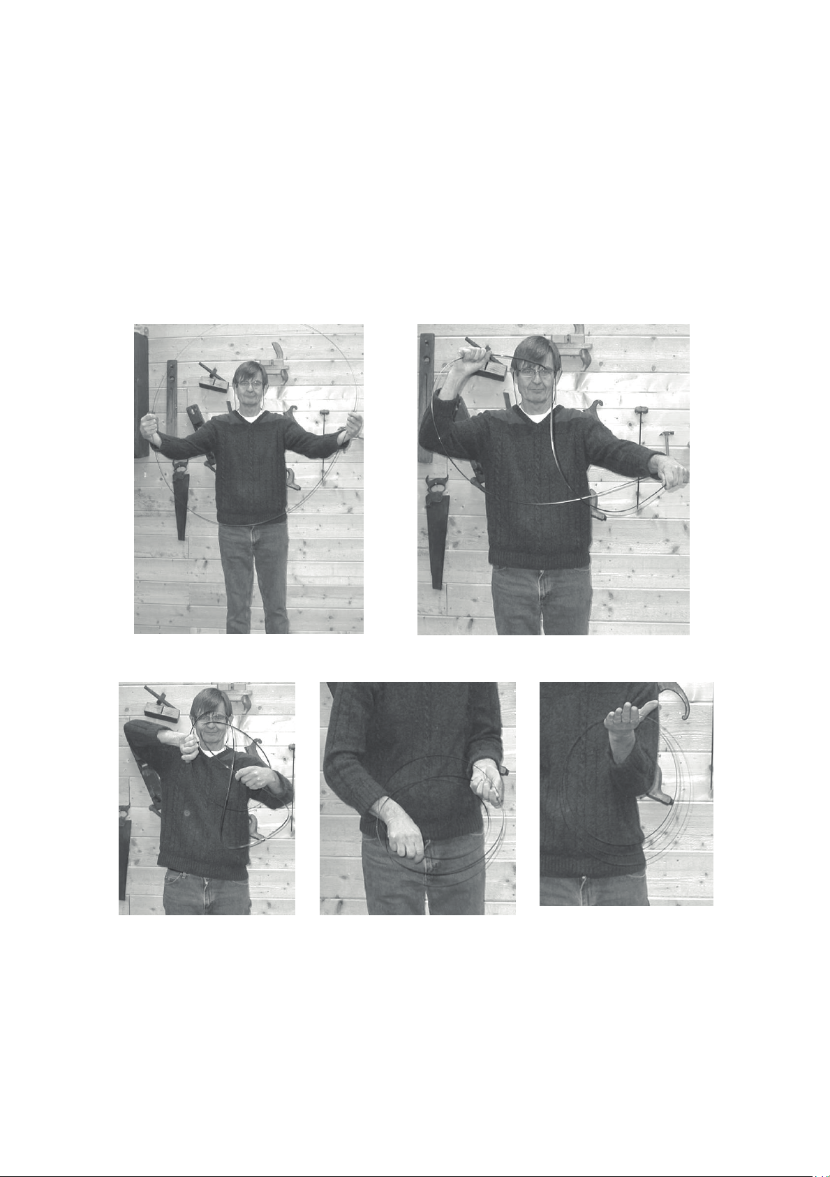
Method Three.
The steering wheel method. Start with the blade in front of you, as if you're holding a
steering wheel with your hands at the 9 o'clock and 3 o'clock positions. Simultaneously
twist your left hand up and your right hand down. As the blade starts to fold, move your
hands closer together while tilting your left hand to the right and your right hand to the left.
The blade will fall into three coils. A variation of this method is to hold the blade as above,
but twist both hands inward, so you're looking at your knuckles and the blade will again fall
into three coils.
Step 1
Step 3
Step 2
Step 4
Done
46
43
Page 44
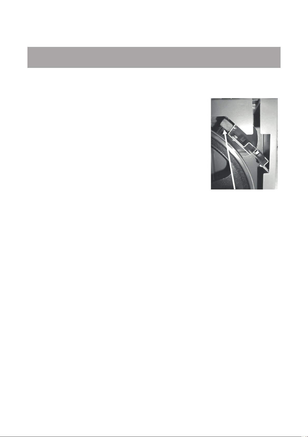
Tire brush
Maintenance.
All tools and machines require regular maintenance, and the bandsaw is no exception. This
section details the general maintenance and care of your bandsaw. In general, we
recommend that you only use a Teflon-based lubricant on the bandsaw. While regular oil
attracts dust and dirt, Teflon tends to dry and has fewer
tendencies to accumulate dirt and sawdust on your machine.
Cleanliness and tire maintenance.
One of the major concerns in regards to the maintenance of the
bandsaw is how clean the tires are. As the saw cuts, some
sawdust lands on the tire of the lower wheel. As the wheel
rotates, the sawdust becomes compressed on the tire. This is
especially true for woods such as pine. The compressed sawdust
could have a negative effect, such as vibration, short blade life
and drifting of the blade. A brush contacts the lower wheel and
helps to prevent buildup. You should inspect the tires regularly to
check that buildup is not happening, especially the lower wheel.
The tires are made of rubber and wear just like car tires. They
wear in the middle, which causes a concavity in the tire. The
deformation makes it hard to track the blades, and for this reason it is important to maintain
the original shape of the tire. The best way to clean the tire surface and maintain the original
shape is to sand it with sandpaper. The old tire surface often hardens and glazes over and
should be redressed occasionally. This can be done by sanding the wheel with 100-grit
sandpaper. This will take off a little of the rubber and expose new rubber, which is desirable.
Rotate the wheels by hand with the blade removed.
Guides.
The ceramic side and back guides should be inspected regularly for cracks and chips. If they
are damaged, they should be replaced as they could damage your blades and bad guides
will detract from the performance of the bandsaw. The guides should be cleaned regularly
and any wood gum or dirt removed. Any commercially available solvent can be used, and
after cleaning they should be lubricated with Teflon-based lubricant.
Drive Belt.
The drive belt should last for many years (depending on the usage) but needs to be inspected
regularly for cracks, cuts and general wear. If damage is found, replace the belt.
44
47
Page 45
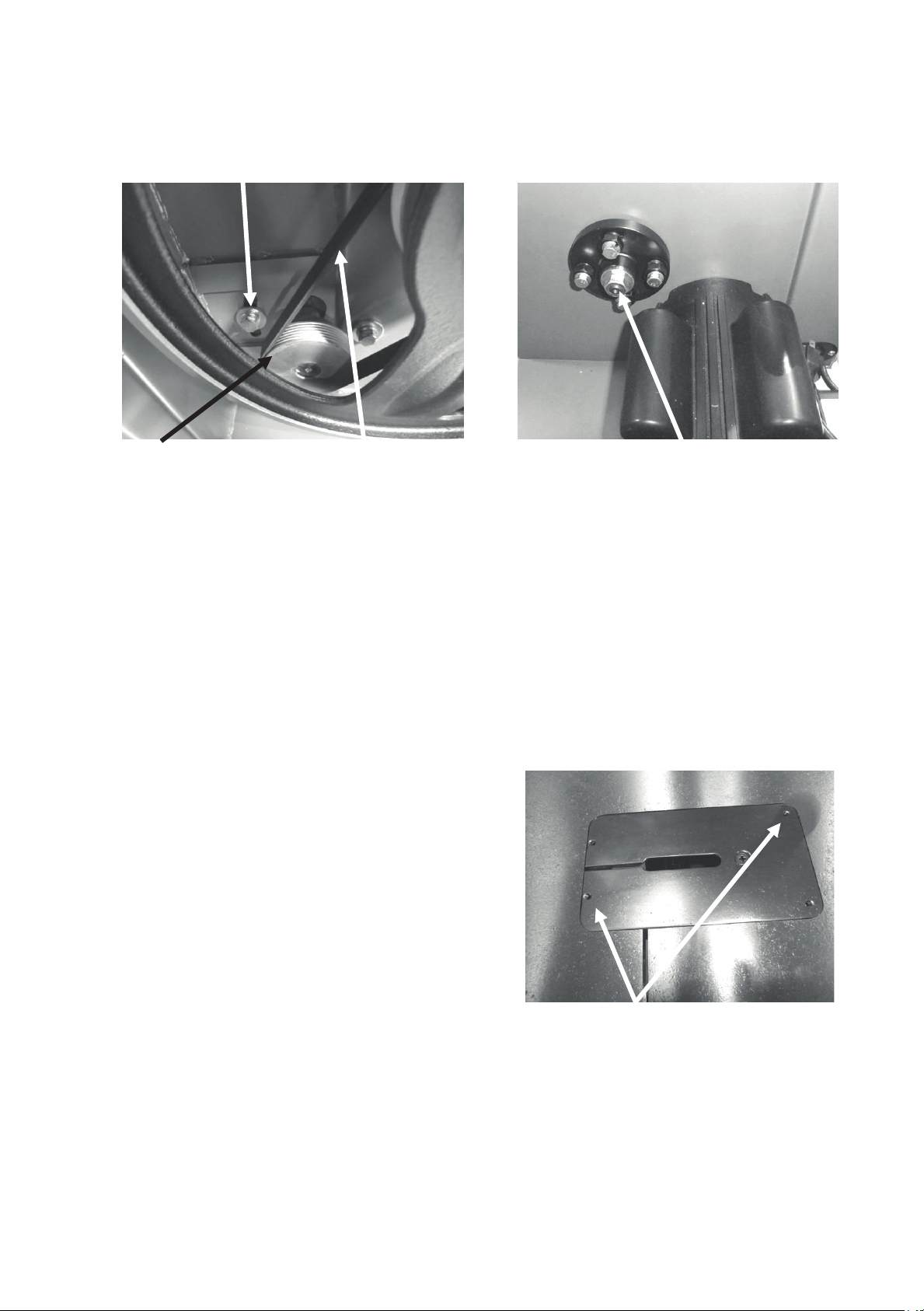
Replacing the drive belt.
Drive belt adjusting bolt
Motor drive pulley Drive belt
Flywheel shaft nut
Throat plate jacking screws
To replace the belts you will have to remove the lower flywheel.
1. Loosen the motor clamp bolts and move the motor so that the tension is completely
removed from the drive belt. Remove the blade. Loosen the two hex nuts that hold the brak
o the bandsaw frame and slide it out of the way of the disc.
t
2. Remove the flywheel shaft nut that clamps the wheel axle (back of the bandsaw)
3. Pull the lower flywheel off the bandsaw. You may have to use a gear puller to remove the
l
ower wheel.
4. Replace the drive belt.
5. Refit the lower wheel and re-clamp with the flywheel shaft nut
Tension the drive belt and tighten the motor clamping bolts.
6.
Note. It is better to replace the drive belt early than to have a breakdown during an
important job.
Note. Take great care not to damage the bearings when taking the flywheel off
reassembling.
.
.
and
e
Table Insert.
The table insert (throat plate) is made of aluminium
and is designed to reduce damage to the blade
should they come in contact. If the blade slot
becomes too wide or the insert becomes damaged
by the blade, it should be replaced. The
replacement insert will have to be fitted to the table
hole. The insert is provided with four jacking screws
that can be adjusted so that the insert is level with
the top of the table.
Bearings.
All bearings are sealed for life and do not require any maintenance. If a bearing becomes
faulty, replace it.
48
45
Page 46
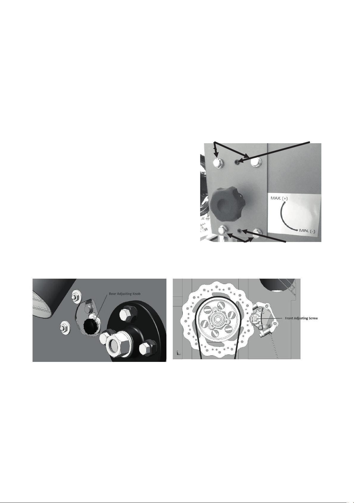
Flywheel not shown for clarity
Clamp bolts C Allen jacking screw D
Clamping bolts A Jack bolt B
Rust.
The bandsaw is made from steel and cast iron. All non-painted surfaces will rust if not
protected. It is recommended that the table be protected by coating with wax if the machine is
not in constant use. All moving non-painted surfaces (guides, rack and pinion, etc.) should be
lubricated/protected with a Teflon-based lubricant.
Blade guide rack and pinion.
The top guide when moved vertically tracks the blade and comes factory-set. Adjustment
is provided should that mechanism become misaligned. This is a tricky operation and
should only be attempted if an extreme error has
occurred.
Back guide forward/back adjustment.
1. Four clamping bolts and two Allen jacking
screws are provided.
2. Slightly loosen the two clamping bolts A and
tighten the bottom Allen screw B will bring the
guide forward.
3. Slightly loosen the two clamping bolts C and
tighten the top Allen screw D will bring the guide
back.
4. Make only very small adjustments. Tighten the
clamping bolts prior to checking the guide vertical
movement.
Note: The machine comes factory-set, and no adjustment should be required.
Adjusting the break.
Back break adjustor
The back break adjustor moves clockwise to remove slack in the break pad.
The front break adjustor is rotated clockwise with an allen key to remove slack in the break
pad.
Front break adjustor
49
46
Page 47
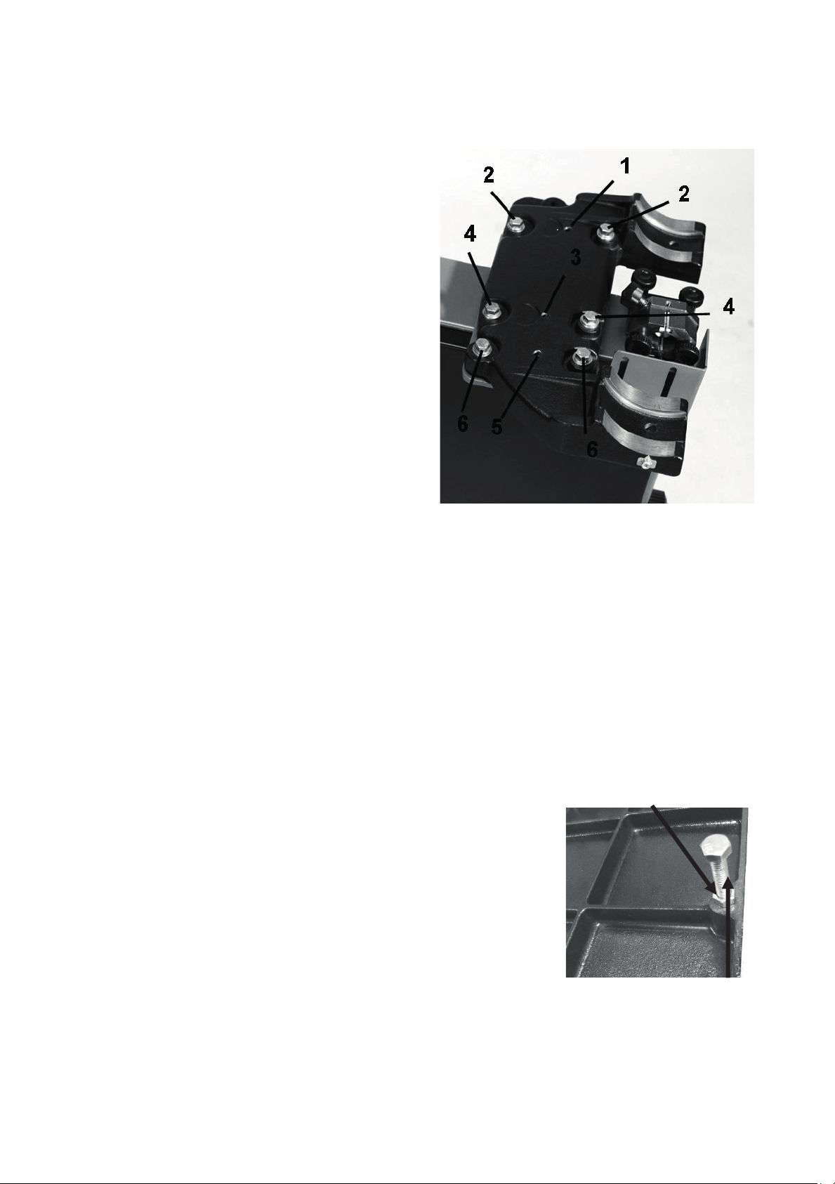
Lock nut
Tilt stop bolt
Adjusting the table square to the bandsaw
blade.
Note. The machine is set in the factory and no
adjustment should be required but during
transportation movement may occur.
To access the adjustment screws, you will
have to tilt the table up to 45 degrees and lock
in position.
The adjustment is made with the jacking
screws 1 & 3 only. Jack screw 5 and clamp
screws 6 are used for support only.
1. Set the table to 90 degrees and place an
engineer's square on the table and check if the
blade is leaning forward or backward. The
blade will be parallel and it is easier to check
the blade at the back.
2. Tilt the table up to 45 degrees and lock in
position.
3. Loosen jack screw 5 and clamp screws 6 [only used for support and not adjustment].
4. If the top of the blade is leaning forward [gap at the top of the engineers square], the back
of the table will have to be adjusted up. Slightly loosen set screw 3 and the two hex head
screws 2, when loosening the clamp hex head screws ensure that they are loosened the
same amount. Then fully tighten set screw 1 and the two hex head screws 4. Only make very
small adjustments as a small movement of the jack screws makes a large adjustment of the
table. Move the table back to 90 degrees, clamp in position and check if the blade is square to
the table with the engineers square. Repeat adjustment if required.
5. If the top of the blade is leaning back [gap at the bottom of the engineers square], the front
of the table will have to be adjusted up. Slightly loosen set screw 3 and the two hex head
screws 2. Then fully tighten set screw 1 and the two hex head screws 4. Only make very
small adjustments as a small movement of the jack screws makes a large adjustment of the
table. Move the table back to 90 degrees, clamp in position and check if the blade is square to
the table with the engineers square. Repeat adjustment if required
6. Once adjustments have been completed, lightly tighten set screw 5 and the two clamp hex
head screws 6. Do not over tighten as this will bend the steel
support plate and may affect the adjustment that you have
made.
Adjusting the table square to blade.
The table has a reference stop bolt that is used to quickly align
the table after tilting. The stop bolt hits the tilt-blanking disc
when it is positioned over the table tilt hole. When the tilt
blanking disc is moved away from the hole, it allows the tilt stop
50
47
Page 48
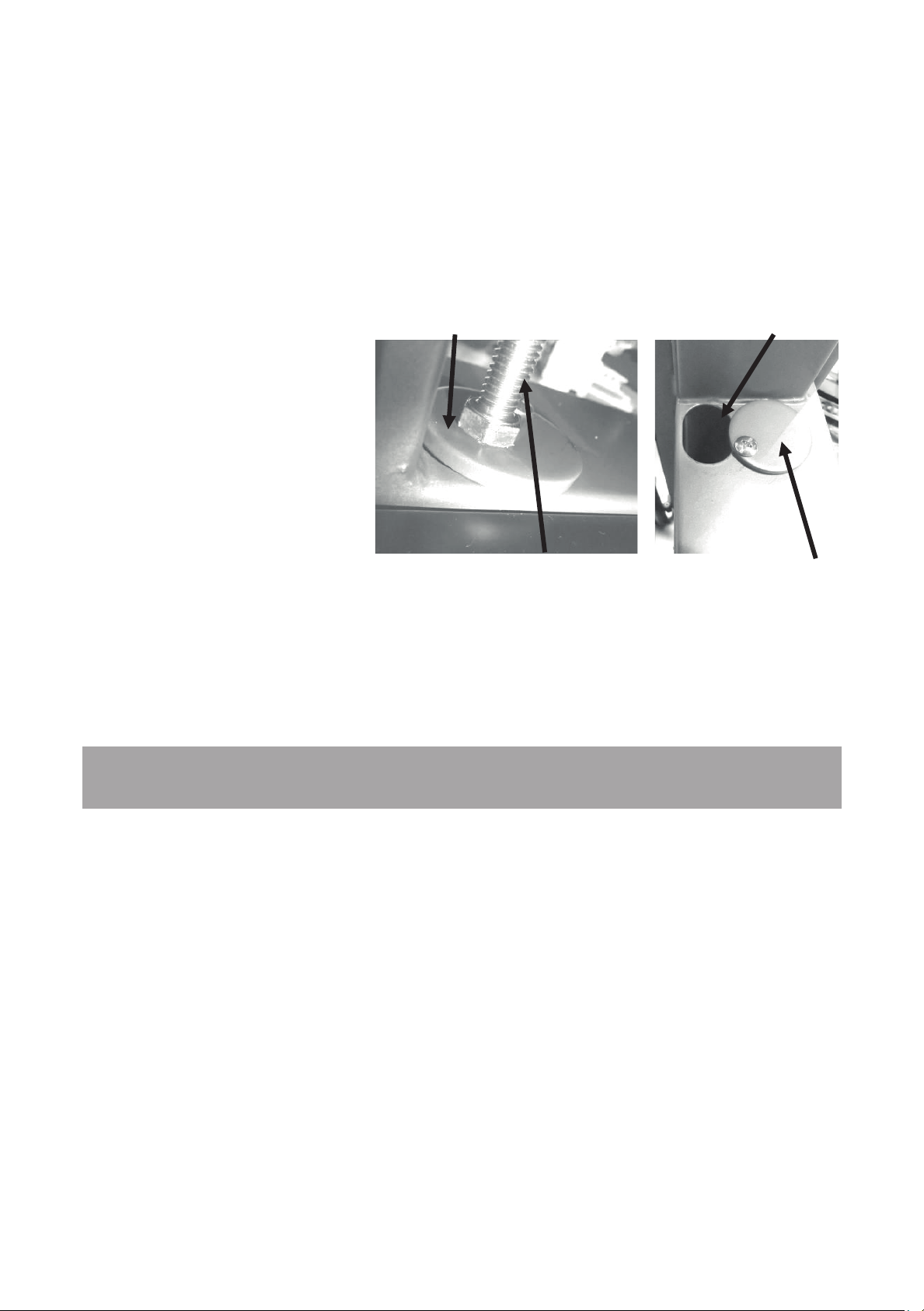
bolt to pass through the table tilt hole, and the table can be moved to the maximum amount of
tilt (-7 degrees).
To adjust the table square to the blade.
1. Check that the stop bolt is in contact with the tilt-blanking disc.
2. Place an engineers square on the table top and bring up to the side of the blade.
3. Check if the blade is square to the table.
4
f adjustment is required loosen the lock nut on the tilt-stop bolt and adjust in the require
. I
di
rection.
Note. Only adjust the tilt-stop
bolt in very small steps.
5. Tighten the lock nut and recheck the blade square to
ta
ble.
. I
6
f additional adjustment is
required repeat above steps
the
.
Tilt blanking disc
Table tilt hole
d
Tilt stop bolt
Troubleshooting.
Ban
dsaw will not start.
1. Check that the start switch is fully pulled out.
2. Check that the yellow safety plug is fully engaged.
3. Check that the electrical power cord is plugged into the power outlet.
4. Check that the electrical supply is on (reset the breaker).
5.
Check that you have the correct power.
The machine will not stop.
This is a very rare occurrence, as the machine is designed to be fail-safe. If it should occur
and you cannot fix the fault, seek professional assistance. The machine must be
disconnected from the power and never run until the fault has been rectified.
1. Stop switch faulty. Replace the stop switch.
Tilt blanking disc
48
51
Page 49

2. Internal breaker faulty. Replace the breaker.
Motor tries to start but will not turn.
1. With the power disconnected from the machine, open the doors and try to turn the wheel by
hand. If the wheel is not turning, check the reason for the jamming. Typical reasons are:
guides too tight, wood jammed in the wheel. Adjust guides or remove jammed wood.
2. Capacitor faulty. Replace the capacitor.
3. Motor faulty. Replace the motor.
Motor overheats.
The motor is designed to run very hot, but should it overheat it has an internal terminal
overload protector that will shut it down until the motor has cooled down and then it will reset
automatically. If the motor overheats, wait until it has cooled down and restart. If the motor
shuts down constantly, check for the reason. Typical reasons are dull blade, overfeeding the
wood, motor cooling fan clogged or faulty, motor cooling fins clogged and excessive ambient
temperature.
Squeaking noise.
1. Check that the motor cooling fan is not contacting the fan cover.
2. Check the bearings.
3. Check the drive belt.
4. Check that the guides are adjusted correctly.
Upper guide shaft is tight or loose.
1. Clean and lubricate.
2. Adjust rack and pinion.
3. Bent rack. Replace the rack.
Blade slows down during a cut.
1. Loose drive belt. Re-tension the belt.
2. Dull blade. Replace the blade or have it re-sharpened.
3. Feeding the wood too fast. Slow down the feed rate.
4. Insufficient set on the teeth (wood nipping the blade). Change blade for a blade with the
correct set.
5. Oil or dirt on the drive belt. Clean or replace the drive belts.
6. Fence not aligned correctly. Align fence.
Blade will not track on flywheels.
1. Bad blade. Change the blade.
2. Crown on the wheels worn or damaged tire. Dress the tires.
The blade kicks.
Bad blade. Replace the blade.
52
49
Page 50

The blade makes a clicking noise.
Bad weld. Dress the weld or change the blade.
Blade overheats.
1. Dull blade. Change the blade or resharpen the blade.
2. Pitch is too small for the depth of cut. Change to a blade with the correct pitch.
3. Guides too tight. Adjust the guides.
4. Wood too hard for the selected blade. Change the blade.
5. Blade too thick for the diameter of the wheels. Change the blade.
Machine vibrates.
1. Machine not level on the floor. Re-level the machine ensuring that it has no movement.
2. Damaged drive belt. Replace the belt.
53
50
Page 51
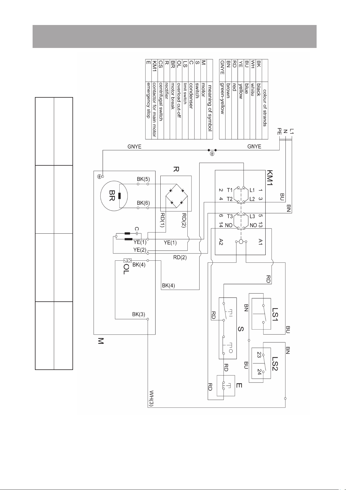
LT14BX 220V wiring diagram.
Manufacturer:
Laguna Tools, Inc.
Product Name:
Wood Working Bandsaw
Model:
14bx
Version:
2022-01
Drawing Originator:
Ting
Checker:
Ting
Authorizes:
Alan Huang
File no.:
LAGUNA-B-0003
54
51
Page 52
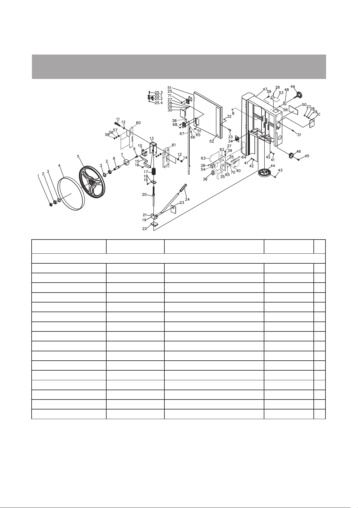
LT14BX Bandsaw exploded view drawing/parts
Supplier part
number
Laguna part No
Upper Wheel Assembly
PBAND1412-175-1 1412-101 Hex Nut M14x1.5- LH 1
PBAND1412-175-2 1412-102 Ball Bearing 6202LLU 2
PBAND1412-175-3 1412-103 C-Ring R35 2
PBAND1412-175-4 1412-104 PU Tire
PBAND1412-175-5 1412-105 Upper Wheel
PBAND1412-175-6 1412-106 Upper Wheel Shaft
PBAND1412-175-7 1412-107 Upper Wheel Shaft Bracket
PBAND1412-175-8 1412-108 Special Nut
PBAND1412-175-9 1412-109 Socket Head Cap Screw 3/8-16UNCx5/8" 1
PBAND1412-175-10 1412-110 Support Bracket
PBAND1412-175-11 1412-111 Hex Cap Screw M10x1.5x80mm 2
PBAND1412-175-12 1412-112 Flat Washer 3/8" 4
PBAND1412-175-13 1412-113 Upper Wheel Bracket Base
PBAND1412-175-14 1412-114 Nylon Inserted Lock Nut M10x1.5 2
PBAND1412-175-15 1412-115 Pointer
PBAND1412-175-16 1412-116 Special Bolt
Item Description Specification Qty
1
1
1
1
1
1
1
1
2
55
52
Page 53

PBAND1412-175-17 1412-117 Spring
#1024UNC×1/2"
MBAND14BX220-250-38-
UK
MBAND14BX2020-250-47-
UK
14BX220-250-147-
UK
PBAND1412-175-18 1412-118 Bracket
PBAND1412-175-19 1412-119 Pin Ø4x20mm 1
PBAND1412-175-20 1412-120 Adjusting Screw
PBAND1412-175-21 1412-121 Blade Tension Arm Assembly
PBAND1412-175-22 1412-122 Support Block
PBAND1412-175-23 1412-123 Plate
PBAND1412-175-24 1412-124 Handle
PBAND1412-175-25 1412-125 Door Hinge Set
PBAND1412-175-25-1 1412-125.1 Door Hinge, Left
PBAND1412-175-25-2 1412-125.2 Door Hinge, Right
PBAND1412-175-25-3 1412-125.3 Socket Head Cap Screw M5x0.8x35mm 2
PBAND1412-175-25-4 1412-125.4 Nylon Inserted Lock Nut M5x0.8 2
PBAND1412-175-26 1412-126 Screw M3.5x10mm 4
PBAND1412-175-27 1412-127 Hex Nut #10-24UNC 4
PBAND1412-175-28 1412-128 Lock Washer #10 4
PBAND1412-175-29 1412-129 Flat Washer #10 4
PBAND1412-175-30 1412-130 Tracking Window
1
1
1
1
1
1
1
2
2
2
2
PBAND1412-175-31 1412-131 Screw
PBAND1412-175-32 1412-132 Hex Nut 1/4-20UNC 1
PBAND1412-175-33 1412-133 Door Stud
PBAND1412-175-34 1412-134 Tension Gauge
MBAND14BX110-175-35 14BX110-175-135 Phillips Flat Head Screw M3x0.5x6mm 6
MBAND14BX110-175-36 14BX110-175-136 ON/ OFF Switch
PBAND1412-175-37 1412-137 Screw M5x0.8x16mm 2
1412-164 Plate
PBAND1412-175-39 1412-139 Washer, Lock-Int. Tooth M5 3
MBAND14BX220-250-40 14BX220-250-140 AC Contactor
PBAND1412-175-41 1412-141 Hex Cap Screw 1/4-20UNCx5/8" 4
PBAND1412-175-42 1412-142 Lock Washer 1/4" 4
PBAND1412-175-43 1412-143 Set Screw 1/4-20UNCx3/8" 2
PBAND1412-175-44 1412-144 Hand Wheel
PBAND1412-175-45 1412-145 Screw 1/4-20UNCx3/4" 1
PBAND1412-175-46 1412-146 Lock Knob
Saw Body
4
1
1
1
3
1
1
1
1
56
53
Page 54

PBAND1412-175-48 1412-148 Lock Knob 1
PBAND1412-175-51-UK
1412-151-UK
1
5/1618UNCx5/8"
MBAND14BX220-250-67-
UK
14BX220-250-167-
UK
MBAND14BX220-250-72-
UK
14BX220-250-172-
UK
Connectors for Junction Boxes
(not shown)
PBAND1412-175-49 1412-149 Adjusting Knob 1
PBAND1412-175-50 1412-150 Tension Label 1
Upper Door
MBAND14BX110-175-52 14BX110-175-152 Logo Label 1
PBAND1412-175-53 1412-153 Hinge Cover 1
MBAND14BX110-175-54 14BX110-175-154 Emergency Stop 1
PBAND1412-175-55 1412-155 Warning Label(not shown) 1
MBAND14BX110-175-56 1412-213 Lock Washer 5/16" 7
MBAND14BX110-175-57 1412-211 Flat Washer 5/16" 6
MBAND14BX110-175-58 1412-338 Hex Nut 5/16-18UNC 6
PBAND1412-175-59 1412-159 Carriage Bolt
PBAND1412-175-60 1412-160 Upper Wheel Bracket Left Side 1
PBAND1412-175-61 1412-161 Upper Wheel Bracket Right Side 1
MBAND14BX110-175-62 14BX110-175-162 Control Panel 1
MBAND14BX110-175-63 14BX110-175-163 Handle 2
MBAND14BX110-175-64 14BX110-175-164 Hex Cap Screw M4x0.7x12mm 2
MBAND14BX110-175-65 14BX110-175-165 Hex Nut M4x0.7 3
PBAND1412-175-66 1412-166 Screw M4x0.7x12mm 1
Connect Bracket 1
MBAND14BX220-250-68 1412-163 Screw M4x0.7x12mm 4
MBAND14BX110-175-70 14BX110-175-170 Plate 1
MBAND14BX220-250-71 1412-162 Screw M3.5x0.6x12mm 4
6
2
57
54
Page 55
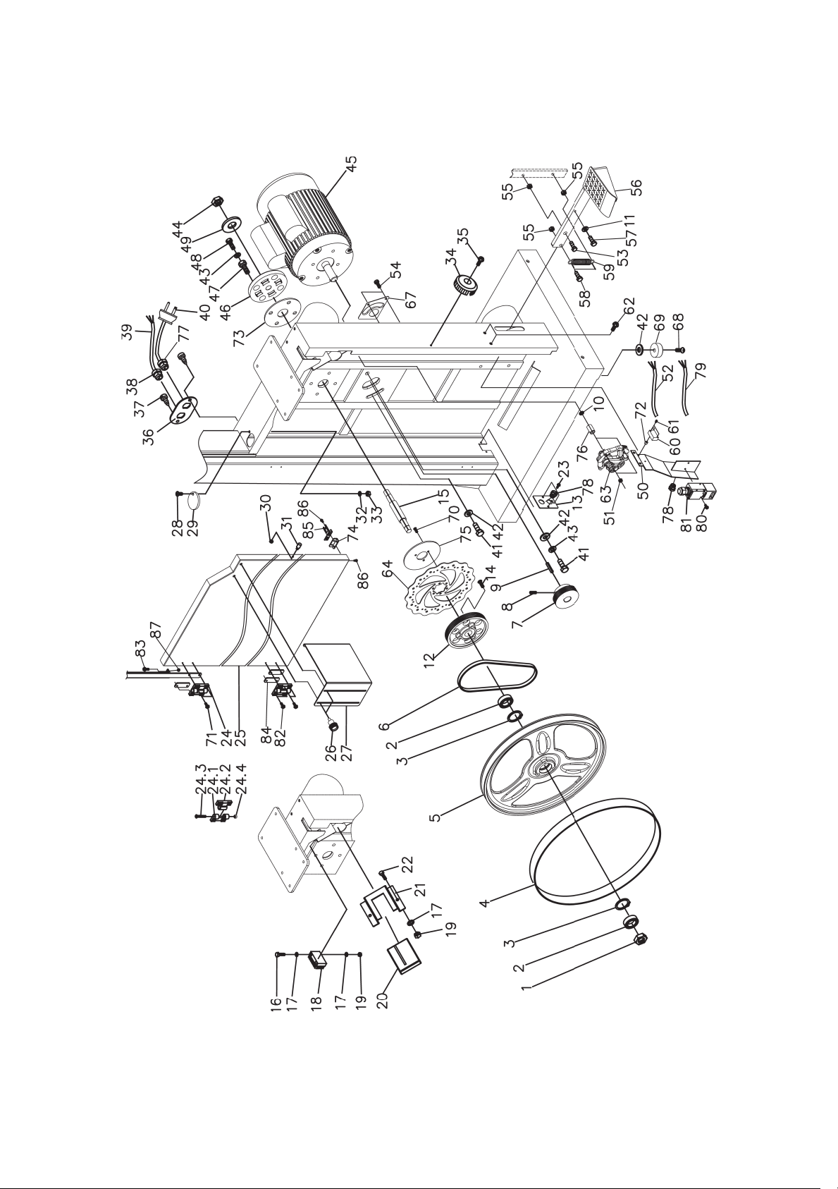
58
55
Page 56

Supplier part
number
5/1618UNCx3/8"
MBAND14BX220-250-2-
13-UK
14BX220-250-213-
UK
5/16-18UNCx11/2"
MBAND14BX220-250-2-
25-UK
14BX220-250-225-
UK
Laguna part No
Item Description Specification Qty
Lower Wheel and Motor Assembly
PBAND1412-175-2-1 1412-101 Hex Nut M14x1.5- LH 1
PBAND1412-175-2-2 1412-102 Ball Bearing 6202LLU 2
PBAND1412-175-2-3 1412-103 C-Ring R35 2
PBAND1412-175-2-4 1412-104 PU Tire
PBAND1412-175-2-5 1412-205 Lower Wheel
PBAND1412-175-2-6 1412-206 Poly-V Belt
PBAND1412-175-2-7 1412-207 Motor Pulley
1
1
1
1
PBAND1412-175-2-8 1412-208 Set Screw
2
PBAND1412-175-2-9 1412-209 Key 6x6x40mm 1
MBAND14BX110-175-2-10 14BX110-175-210 Flat Washer 1/4" 2
PBAND1412-175-2-11 1412-211 Flat Washer 5/16" 2
MBAND14BX110-175-2-12 14BX110-175-212 Spindle Pulley
Plate
MBAND14BX110-175-2-14 14BX110-175-214 Phillips Flat Head Screw
PBAND1412-175-2-15 1412-215 Lower Spindle
1
1
3
1
PBAND1412-175-2-16 1412-216 Hex Cap Screw M5x0.8x30mm 2
PBAND1412-175-2-17 1412-129 Flat Washer #10 6
PBAND1412-175-2-18 1412-218 Brush
1
PBAND1412-175-2-19 1412-140 Hex Nut M5x0.8 4
PBAND1412-175-2-20 1412-220 Insert Block
PBAND1412-175-2-21 1412-221 Shelf
1
1
PBAND1412-175-2-22 1412-222 Hex Cap Screw M5x0.8x8mm 2
PBAND1412-175-2-23 1412-126 Screw M3.5x0.6x10mm 2
PBAND1412-175-2-24 1412-125 Door Hinge Set
PBAND1412-175-2-24-1 1412-125.1 Door Hinge, Left
PBAND1412-175-2-24-2 1412-125.2 Door Hinge, Right
2
2
2
PBAND1412-175-2-24-3 1412-125.3 Socket Head Cap Screw M5x0.8x35mm 2
PBAND1412-175-2-24-4 1412-125.4 Nylon Inserted Lock Nut M5x0.8 2
Lower Door
PBAND1412-175-2-26 1412-226 Lock Knob
PBAND1412-175-2-27-UK 1412-227-UK Lower Blade Guard
1
2
1
PBAND1412-175-2-28 1412-228 Screw 1/4-20UNCx3/4" 1
PBAND1412-175-2-29 1412-229 Plate
1
56
Page 57

PBAND1412-175-2-30 1412-132 Hex Nut 1/4-20UNC 1
#1024UNC×3/8"
MBAND14BX220-250-2-
39-UK
14BX220-250-239-
UK
MBAND14BX220-250-2-
40-UK
14BX220-250-240-
UK
MBAND14BX220-250-2-
45-UK
14BX220-250-245-
UK
PBAND1412-175-2-
45MFC-UK
MBAND14BX220-250-2-
45JB-UK
14BX220-250-
245JB-UK
MBAND14BX220-250-2-
45JBC
14BX220-250-
245JBC
MBAND14BX220-250-2-
45SC
3/8-16UNC×13/4"
MBAND14BX220-250-2-
50-UK
14BX220-250-250-
UK
MBAND14BX220-250-2-
52-UK
14BX220-250-252-
UK
PBAND1412-175-2-31 1412-133 Door Stud 1
PBAND1412-175-2-32 1412-232 Flat Washer 1/4" 1
PBAND1412-175-2-33 1412-233 Nylon Inserted Lock Nut 1/4-20UNC 1
PBAND1412-175-2-34 1412-146 Lock Knob 1
PBAND1412-175-2-35 1412-145 Screw 1/4-20UNCx3/4" 1
PBAND1412-175-2-36-UK 1412-236-UK Plate 1
PBAND1412-175-2-37 1412-237 Screw
PBAND1412-175-2-38-UK 1412-238-UK Strain Relief PG-13.5 2
Motor Cord 1
Power Cord 1
PBAND1412-175-2-41 1412-241 Hex Cap Screw 3/8-16UNCx1" 2
PBAND1412-175-2-42 1412-242 Flat Washer 3/8" 6
PBAND1412-175-2-43 1412-243 Lock Washer 3/8" 5
PBAND1412-175-2-44 1412-244 Hex Nut M14x1.5 1
Motor 1
PBAND1412-175-2-45MF 1412-245MF Motor Fan (not shown) 1
1412-245MFC-UK Motor Fan Cover (not shown) 1
Junction Box (not shown) 1
Junction Box Cover (not shown) 1
PBAND1412-175-2-45MB 1412-245MB Motor Break (not shown) 1
PBAND1412-175-2-45RR 1412-245RR Rectifier (not shown) 1
2
14BX220-250-245SC Start Capacitor 150MF 250VAC 1
MBAND14BX220-250-2-
45RC-UK
PBAND1412-175-2-46 1412-246 Spindle Holder 1
PBAND1412-175-2-47 1412-247 Adjusting Screw 4
PBAND1412-175-2-48 1412-248 Hex Cap Screw
PBAND1412-175-2-49 1412-249 Flat Washer 3/4" 1
MBAND14BX110-175-2-51 14BX110-175-251 Hex Nut M6x1.0 2
MBAND14BX110-175-2-53 14BX110-175-253 Hex Cap Screw 3/8-16UNC×3/4" 1
14BX220-25
0-245RC Running Capacitor 35uF 400VAC 1
4
Switch Cover 1
Limit Switch Cord 1
60
57
Page 58

MBAND14BX110-175-2-54 14BX110-175-254 Hex Cap Screw M6x1.0x35mm 2
5/1618UNCx1/2"
3/8-16UNCx11/4"
MBAND14BX110-175-2-
63P
MBAND14BX220-250-2-
74-UK
14BX220-250-274-
UK
Bracket-Safety Interlock Switch
Pin
MBAND14BX220-250-2-
79-UK
14BX220-250-279-
UK
MBAND14BX110-175-2-55
MBAND14BX110-175-2-56 14BX110-175-256 Foot Brake
1412-336 Hex Nut 3/8-16UNC 3
1
MBAND14BX110-175-2-57 14BX110-175-257 Socket Head Cap Screw
MBAND14BX110-175-2-58 14BX110-175-258 Hex Cap Screw
MBAND14BX110-175-2-59 14BX110-175-259 Spring
MBAND14BX110-175-2-60 14BX110-175-260 Limit Switch
MBAND14BX110-175-2-61 14BX110-175-261 Screw M3×20mm 2
MBAND14BX110-175-2-62 14BX110-175-262 Screw 1/4-20UNCx3/8" 2
MBAND14BX110-175-2-63 14BX110-175-263 Brake Assembly
14BX110-175-263P Brake Pad (not shown), 2 pieces
MBAND14BX110-175-2-64 14BX110-175-264 Disc
MBAND14BX110-175-2-65 14BX110-175-265 Inner Cable (not shown)
MBAND14BX110-175-2-66 14BX110-175-266 Housing (not shown)
MBAND14BX110-175-2-67 14BX110-175-267 Plate
MBAND14BX110-175-2-68
MBAND14BX110-175-2-69
MBAND14BX110-175-2-70 14BX110-175-270 Socket Head Button Screw M5x0.8x12mm 3
MBAND14BX220-250-2-71
MBAND14BX110-175-2-72 14BX110-175-272 Spacer
MBAND14BX110-175-2-73 14BX110-175-273 Plate
MBAND14BX110-175-2-75 14BX110-175-275 Plate
MBAND14BX110-175-2-76 14BX110-175-276 Spacer
MBAND14BX110-175-2-77
MBAND14BX110-175-2-78
1412-507 Socket Head Button Screw 3/8-16UNCx1" 4
1412-508 Rubber Pad
1412-163 Screw M4x0.7x12mm 4
1412-250 Strain Relief PG-11 1
1412-256 Strain Relief PG-9 3
Safety Interlock Switch Cord
1
2
1
1
1
1
1
1
1
4
2
1
1
1
2
1
MBAND14BX110-175-2-80
MBAND14BX110-175-2-81
MBAND14BX110-175-2-82
MBAND14BX110-175-2-83
MBAND14BX110-175-2-84
MBAND14BX110-175-2-85
MBAND14BX110-175-2-86
MBAND14BX110-175-2-87
1412-261 Screw M4x0.7x30mm 2
1412-262 Safety Interlock Switch QKS8 1
1412-162 Screw M3.5x0.6x12mm 4
1412-166 Screw M4x0.7x12mm 1
1412-164 Plate
1412-260 Safety Interlock Switch Pin
1412-258 Screw M4x0.7x6mm 4
1412-168 Hex Nut M4x0.7 1
3
1
615862
Page 59
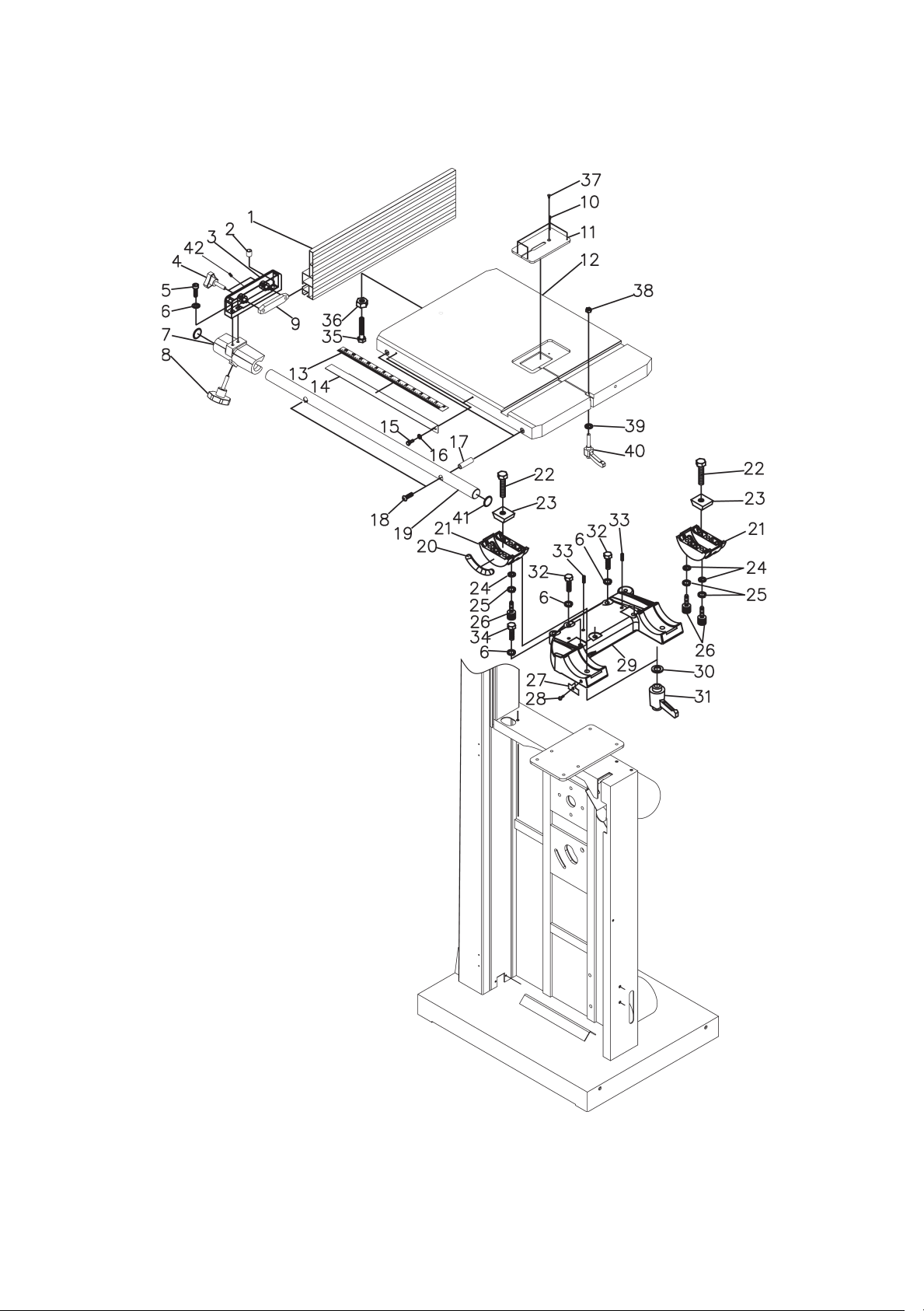
59
Page 60

Laguna part No
Supplier part
number
5/1618UNCx3/4"
5/16-18UNCx11/4"
5/1618UNCx5/8"
Table and Fence Assembly
PBAND1412-175-3-1 1412-301 Aluminum Fence 1
PBAND1412-175-3-2 1412-302 Plastic Adjusting Screw 1
PBAND1412-175-3-3 1412-303 Fence Body 1
PBAND1412-175-3-4 1412-304 Lock Knob 2
Item Description Specification Qty
PBAND1412-175-3-5 1412-305 Socket Head Cap Screw
PBAND1412-175-3-6 1412-213 Lock Washer 5/16" 10
PBAND1412-175-3-7 1412-307 Fence Head 1
PBAND1412-175-3-8 1412-308 Lock Knob 1
PBAND1412-175-3-9 1412-309 Lock Bar 1
PBAND1412-175-3-10 1412-310 Set Screw M4x0.7x4mm 4
PBAND1412-175-3-11 1412-311 Table Insert 1
PBAND1412-175-3-12 1412-312 Table 1
PBAND1412-175-3-13 1412-313 Scale 1
PBAND1412-175-3-14 1412-314 Scale Plate 1
PBAND1412-175-3-15 1412-315 Hex Cap Screw M5x0.8x10mm 2
PBAND1412-175-3-16 1412-129 Flat Washer #10 2
PBAND1412-175-3-17 1412-317 Bushing 2
PBAND1412-175-3-18 1412-318 Socket Head Cap Screw 5/16-18UNCx2" 2
PBAND1412-175-3-19 1412-319 Steel Tube 1
PBAND1412-175-3-20 1412-320 Scale 1
PBAND1412-175-3-21 1412-321 Trunnion 2
PBAND1412-175-3-22 1412-322 Hex Cap Screw M10x1.5x50mm 2
PBAND1412-175-3-23 1412-323 Slide Block 2
PBAND1412-175-3-24 1412-324 Flat Washer 1/4" 6
PBAND1412-175-3-25 1412-142 Lock Washer 1/4" 6
PBAND1412-175-3-26 1412-326 Socket Head Cap Screw M6x1.0x16mm 6
PBAND1412-175-3-27 1412-327 Pointer 1
PBAND1412-175-3-28 1412-328 Screw M5x0.8x8mm 1
PBAND1412-175-3-29 1412-329 Bracket 1
PBAND1412-175-3-30 1412-242 Flat Washer 3/8" 2
PBAND1412-175-3-31 1412-331 Lock Handle 2
3
PBAND1412-175-3-32 1412-332 Hex Cap Screw
PBAND1412-175-3-33 1412-333 Set Screw
3
2
63
60
Page 61

PBAND1412-175-3-34 1412-334 Hex Cap Screw
5/16-18UNCx13/4"
PBAND1412-175-3-35 1412-335 Hex Cap Screw 3/8-16UNC×2" 1
PBAND1412-175-3-36 1412-336 Hex Nut 3/8-16UNC 1
PBAND1412-175-3-37 1412-337 Phillips Flat Head Screw M4x0.7x8mm 1
PBAND1412-175-3-38 1412-338 Hex Nut 5/16-18UNC 1
PBAND1412-175-3-39 1412-211 Flat Washer 5/16" 1
PBAND1412-175-3-40 1412-340 Lock Handle 1
PBAND1412-175-3-41 1412-341 Rubber Cover 2
PBAND1412-175-3-42 1412-342 Set Screw 1/4-20UNCx1/4" 2
3
64
61
Page 62
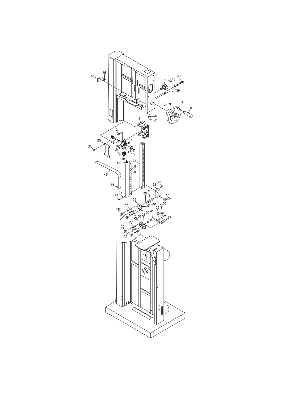
65
62
Page 63

Laguna part No
Supplier part
number
5/1618UNCx3/8"
5/16-18UNCx11/4"
Upper and Lower Blade Guides Assembly
PBAND1412-175-4-1 1412-401 Lock Knob 1
Item Description Specification Qty
PBAND1412-175-4-2 1412-208 Set Screw
PBAND1412-175-4-3 1412-143 Set Screw 1/4-20UNCx3/8" 1
PBAND1412-175-4-4 1412-404 Hand Wheel 1
PBAND1412-175-4-5 1412-405 Handle 1
PBAND1412-175-4-6 1412-406 Pointer 1
PBAND1412-175-4-7 1412-407 Screw 1/4-20UNCx3/8" 1
PBAND1412-175-4-8-UK 1412-408-UK Upper Blade Guard 1
PBAND1412-175-4-9 1412-409 Height Scale 1
PBAND1412-175-4-10 1412-410 Magnet 1
PBAND1412-175-4-11 1412-411 Guide Bar Bracket 1
PBAND1412-175-4-12 1412-412 Socket Head Cap Screw
PBAND1412-175-4-13 1412-413 C-Ring S12 1
PBAND1412-175-4-14 1412-414 Worm 1
PBAND1412-175-4-15 1412-415 E-Ring E8 2
PBAND1412-175-4-16 1412-416 Gear Base 1
PBAND1412-175-4-17 1412-417 Bushing 1
PBAND1412-175-4-18-UK 1412-418-UK Shaft 1
PBAND1412-175-4-19 1412-419 Gear 1
PBAND1412-175-4-20 1412-420 Plate 1
PBAND1412-175-4-21-UK 1412-421-UK Special Screw 4
PBAND1412-175-4-22 1412-422 Guide Bar 1
PBAND1412-175-4-23 1412-423 Socket Head Cap Screw 1/4-20UNCx5/8" 4
PBAND1412-175-4-24 1412-142 Lock Washer 1/4" 2
PBAND1412-175-4-25 1412-425 Lock Knob 4
PBAND1412-175-4-26 1412-426 Ceramic Guide 8
PBAND1412-175-4-27 1412-427 Adjusting Block 4
PBAND1412-175-4-28 1412-428 Fixed Block 2
PBAND1412-175-4-29 1412-429 Lock Knob 1
PBAND1412-175-4-30 1412-430 Ceramic Guide 2
PBAND1412-175-4-31 1412-431 Support Shaft 1
PBAND1412-175-4-32 1412-432 Guide Bracket 1
PBAND1412-175-4-33 1412-433 Lock Handle 1
PBAND1412-175-4-34 1412-434 Support Shaft 1
2
2
66
63
Page 64

PBAND1412-175-4-35 1412-435 Lock Knob 1
PBAND1412-175-4-36 1412-436 Socket Head Button Screw 1/4-20UNCx1/2" 2
PBAND1412-175-4-37 1412-437 Base 1
PBAND1412-175-4-38 1412-438 Special Bolt 2
PBAND1412-175-4-39 1412-439 Steel Ball 1
PBAND1412-175-4-40 1412-440 Hex Cap Screw 5/16-18UNCx1" 4
PBAND1412-175-4-41 1412-213 Lock Washer 5/16" 4
PBAND1412-175-4-42 1412-211 Flat Washer 5/16" 4
PBAND1412-175-4-43 1412-443 Guide Plate 1
PBAND1412-175-4-44 1412-116 Special Bolt 2
PBAND1412-175-4-45 1412-445 Slide Guard 1
PBAND1412-175-4-46 1412-446 Screw M4x0.7x8mm 2
64
67
Page 65
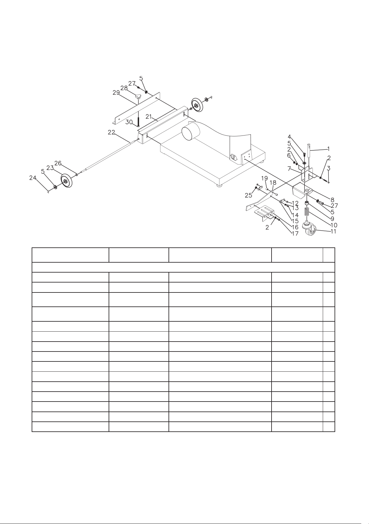
Laguna part No
Supplier part
number
1/4-20UNCx13/4"
5/1618UNCx1/2"
Mobility System: Optional
PBAND1412-175-6-1 1412-601 Rod 1
PBAND1412-175-6-2 1412-232 Flat Washer 1/4" 6
Item Description Specification Qty
PBAND1412-175-6-3 1412-603 Socket Head Cap Screw
PBAND1412-175-6-4 1412-421 Socket Head Button Screw
PBAND1412-175-6-5 1412-605 Flat Washer 5/16" 11
PBAND1412-175-6-6 1412-606 Nylon Inserted Lock Nut 1/4-20UNC 2
PBAND1412-175-6-7 1412-607 Fixed Plate 1
PBAND1412-175-6-8 1412-608 Wheel Bracket 1
PBAND1412-175-6-9 1412-609 DU Bearing MB1620DU 1
PBAND1412-175-6-10 1412-610 Spring 1
PBAND1412-175-6-11 1412-611 Caster 1
PBAND1412-175-6-12 1412-612 Spacer 2
PBAND1412-175-6-13 1412-613 Flat Washer M5 1
PBAND1412-175-6-14 1412-614 Screw M5x0.8x20mm 1
PBAND1412-175-6-15 1412-615 Connecting Plate 2
2
2
68
65
Page 66

PBAND1412-175-6-16 1412-616 Foot Pedal 1
5/1618UNCx3/4"
PBAND1412-175-6-17 1412-617 Socket Head Button Screw 1/4-20UNCx3/8" 2
PBAND1412-175-6-18 1412-618 Plate 1
PBAND1412-175-6-19 1412-619 Spacer 2
PBAND1412-175-6-20 1412-620 Support Plate 1
PBAND1412-175-6-21 1412-621 Support Plate 1
PBAND1412-175-6-22 1412-622 Rod 1
PBAND1412-175-6-23 1412-623 Wheel 2
PBAND1412-175-6-24 1412-624 Retaining Pin R8 2
PBAND1412-175-6-25 1412-125.4 Nylon Inserted Lock Nut M5x0.8 1
PBAND1412-175-6-26 1412-626 Bushing 2
PBAND1412-175-6-27 1412-627 Socket Head Button Screw
PBAND1412-175-6-28 1412-628 Knob 1
PBAND1412-175-6-29 1412-629 Support Plate 1
PBAND1412-175-6-30 1412-630 Hex Cap Screw M8x1.25x70mm 1
7
69
66
Page 67
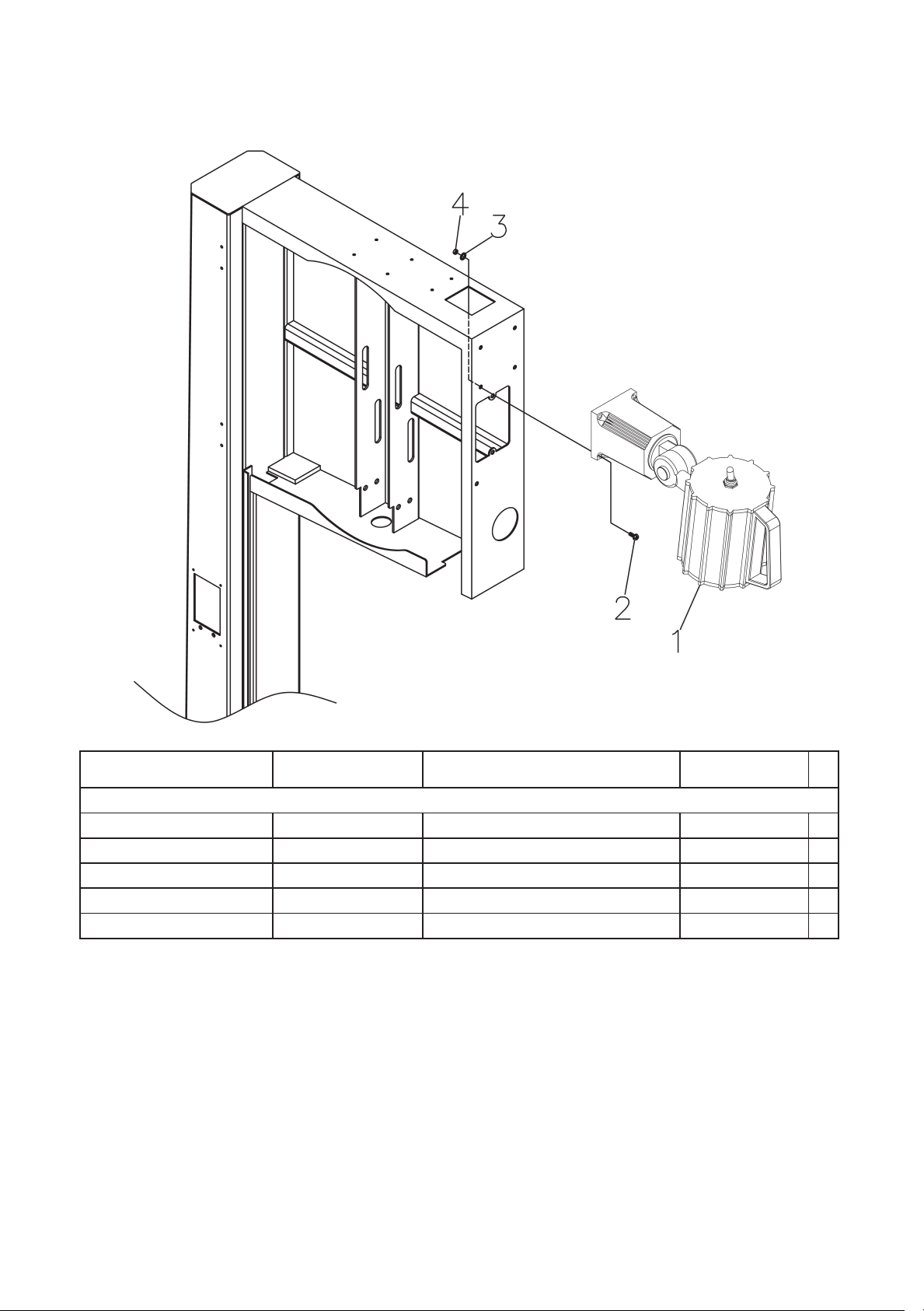
Supplier part
number
Laguna part No
Industrial Work Light: Optional
PBAND1412-175-7-1 1412-701 Work Light 1
PBAND1412-175-7-2 1412-702 Screw M4x0.7x20mm 4
PBAND1412-175-7-3 1412-703 Flat Washer M4 4
PBAND1412-175-7-4 1412-704 Hex Nut M4x0.7 4
PBAND1412-175-7-5 1412-705 Cable Clamp (not shown) 3
Item Description Specification Qty
70
67
Page 68
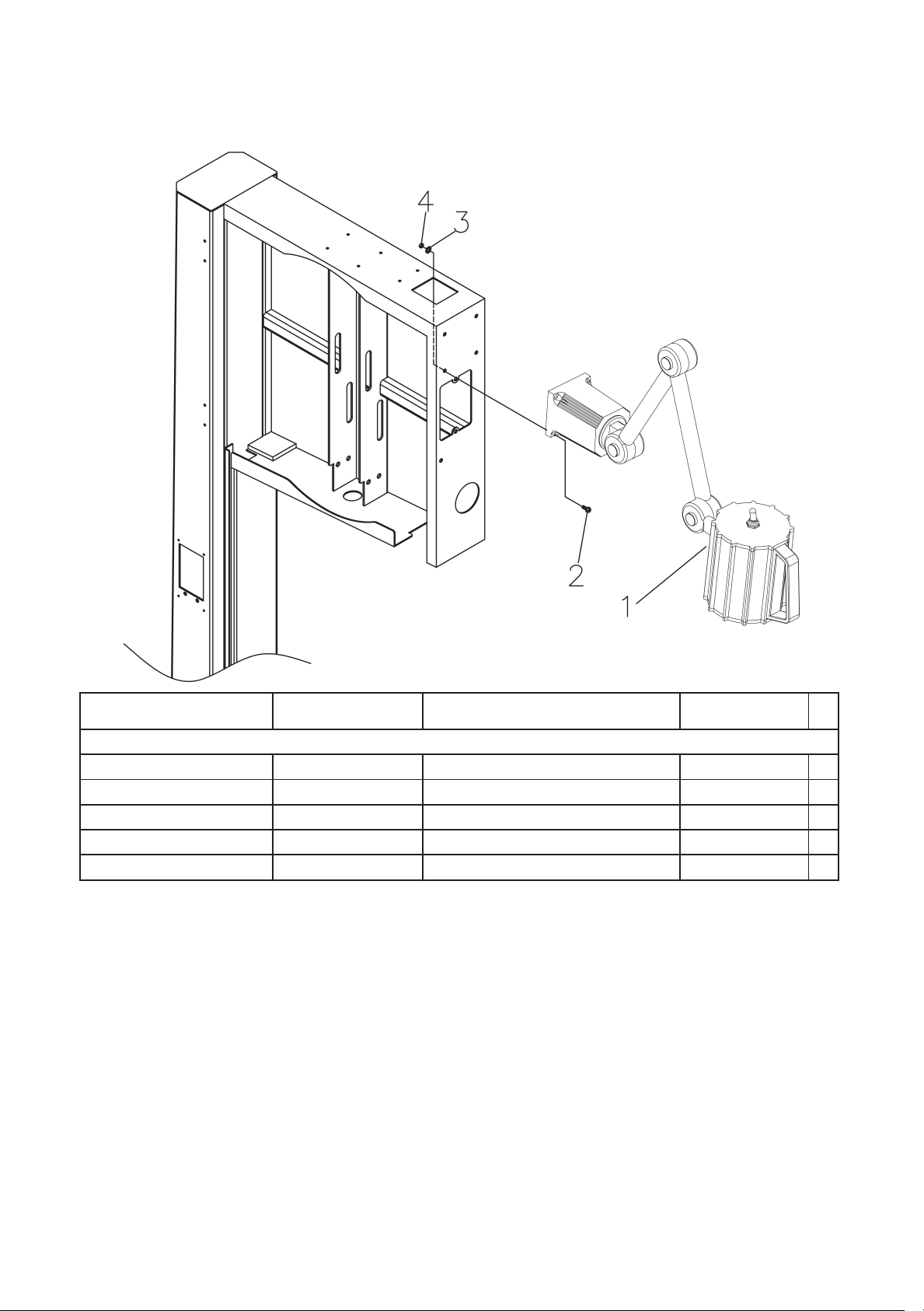
Supplier part
number
Laguna part No
Industrial Work Light: Optional
PBAND14BX220-250-7-1 14BX220-250-701 Work Light 230V 1
PBAND1412-175-7-2 1412-702 Screw M4x0.7x20mm 4
PBAND1412-175-7-3 1412-703 Flat Washer M4 4
PBAND1412-175-7-4 1412-704 Hex Nut M4x0.7 4
PBAND1412-175-7-5 1412-705 Cable Clamp (not shown) 3
Item Description Specification Qty
71
68
Page 69

69
Page 70

Declaration of Conformity
Product model: 14-BX Bandsaw
Name and address of the manufacturer: Laguna Tools Inc. 2072 Alton Parkway, Irvine, California
92606, USA.
Name and address of the UK Authorised Representative: Axminster Tool Centre Ltd, Unit 10 Weycroft
Avenue, Axminster, Devon EX13 5PH, United Kingdom.
This declaration of conformity is issued under the sole responsibility of the manufacturer.
Object of the declaration: 14-BX Bandsaw
Laguna Tools Inc.
CLARATION OF CONFORMITY
UK DE
‘original’
The object of the declaration described above is in conformity with the relevant GB legislation:
Supply of Machinery (Safety) Regulations 2008 as amended.
Electromagnetic Compatibility Regulations 2016 as amended.
References to the relevant harmonised standards used or references to the other technical
specifications in relation to which conformity is declared:
EN ISO 12100:2010 Safety of Machinery. General principles for design. Risk assessment and risk reduction.
EN 1807-1-2013 Safety of woodworking machines - Band sawing machines - Part 2: Log sawing machines
EN60204-1:2018 Safety of machinery - Electrical equipment of machines - Part 1: General requirements (IEC 602041:2016, modified)
ISO 13849-1:2023 Safety of machinery - Safety-related parts of control systems - Part 1: General principles for design
(ISO 13849-1:2023)
EN 50370-1:2005 Electromagnetic compatibility (EMC) - Product family standard for machine tools - Part 1: Emission
EN 50370-2:2003 Electromagnetic compatibility (EMC) - Product family standard for machine tools - Part 2: Immunity
EN 61000-4-2:2009 Electromagnetic compatibility (EMC) -- Part 4-2: Testing and measurement techniques Electrostatic discharge immunity test
EN 61000-4-4:2012 Electromagnetic compatibility (EMC) - Part 4-4: Testing and measurement techniques - Electrical
fast transient/burst immunity test
IEC 61000-4-6:2023 Electromagnetic compatibility (EMC) - Part 4-6: Testing and measurement techniques - Immunity
to conducted disturbances, induced by radio-frequency fields
Additional information:
Name and address of person authorised to compile the technical file: Axminster Tool Centre
Ltd, Unit 10 Weycroft Avenue, Axminster, Devon EX13 5PH, United Kingdom
The machinery fulfils all relevant provisions of Supply of Machinery (Safety) Regulations 2008
as amended.
Signed for and behalf of: Axminster Tool Centre Ltd.
(place and date of issue): Axminster, Devon, United Kingdom, 20
(name, function):
Andrew Parkhouse, Supply Chain Director
Signature:
70
th
June 2024
Page 71

Warranty
New machines and accessories sold by Laguna Tools carry a one-year
warranty effective from the date of shipping.
Laguna Tools guarantees all new machines and accessories sold to be
free of manufacturers’ defective workmanship, parts and materials.
We will repair or replace, without charge, any parts determined by
Laguna Tools, Inc. to be a manufacturer’s defect.
We require that the defective item/part be returned to the Laguna
appointed dealer you purchased from with the complaint. Photographic / videos maybe required when any fault is reported so we can
agree action needed. Any machines returned to Laguna appointed dealer must be returned with packaging in the same manner
in which it was received. If a part or blade is being returned it must
have adequate packaging to ensure no damage is received during
shipping. In the event the item/part is determined to be damaged
due to lack of maintenance, cleaning or misuse/abuse, the customer
will be responsible for the cost to replace the item/part, plus all related shipping charges. This limited warranty does not apply to natural
disasters, acts of terrorism, normal wear and tear, product failure due
to lack of maintenance or cleaning, damage caused by accident,
neglect, lack of or inadequate dust collection, misuse/abuse or damage caused where repair or alterations have been made or attempted
by others. Laguna Tools, Inc. is not responsible for additional tools or
modifications sold or performed (other than from/by Laguna Tools,
Inc.) on any Laguna Tools, Inc. machine.
Warranty maybe voided upon the addition of such described tools
and/or modifications, determined on a case-by-case basis.
Normal user alignment, adjustment, tuning, machine settings and
consumables I.E; blades are not covered by this warranty. It is the
responsibility of the user to understand basic machinery operation,
settings and procedures and to properly maintain the equipment in
accordance with the standards provided by the manufacturer.
The labour required to install replacement parts is the responsibility
of the user. Laguna Tools is not responsible for damage or loss caused
by a freight company or other circumstances not in our control.
All claims for loss or damaged goods must be notified to the authorised dealer within twenty-four hours, if the machine is received damaged it must be signed for damaged.
Only new machines sold to the original owner are covered by this
warranty.
71
Page 72

Distributed by
The packaging is suitable for recycling.
Please dispose of it in a responsible manner.
EU Countries Only
Do not dispose of electric tools together with household waste material.
By law they must be collected and recycled separately.
For after sales help visit
axminstertools.com or call 03332 406406
Axminster Tools, Axminster Devon EX13 5PH
 Loading...