

Page 1
Page 2

Page 3

WELCOME ABOARD
We share a common passion for the sea; we, LAGOON, as catamaran builders and you who want to live your passion on the
seven seas.
We are delighted to welcome you to the family of LAGOON catamaran owners and we congratulate you on it.
This instruction guide is intended to help you to enjoy your boat in comfort and safety. It includes the boat specifications, the
equipment provided or installed, the systems on board and tips on her use and maintenance.
We advise you to read this guide carefully before setting sail in order to take the greatest advantage of your sailing.
Our network of LAGOON official retailers is entirely at your disposal in order to help you discovering your boat. They will be
the most able to do the maintenance on your boat.
Page 4

Page 5

This user guide is a tool that will enable you to get to know your boat and apprehend the use of the components that are necessary for running her.
A WAY TO MAKE THE MOST OF THIS USER GUIDE
In order to have an easier apprehension, this guide offers you two complementary reading levels:
. The pages with text on the right hand side of the document develop the different subjects dealt with in the chapters,
. The pages on the left hand side are given to the related photos, layouts or block diagrams.
The different warnings used throughout this guide are as follows:
Before you put out to sea, please read the owner’s manual (CE standard manual) delivered with your boat and please follow the instructions.
PREAMBULE
Shows a piece of advice to do the appropriate actions or
manoeuvres adapted to what you are thinking of doing.
Draws your attention on dangerous ways of doing that may
bring about injuries to people or damages to the boat or her
components.
Warns you about the existence of a hazard that may have
serious or fatal consequences if the appropriate precautions
are not taken.
WARNING
DANGER
RECOMMENDATION
Page 6

Page 7

CONTENTS
1. SPECIFICATIONS
1. SPECIFICATIONS
............................
............................
PAGE 7
PAGE 7
1.1 I D of your boat
1.1 I D of your boat
1.2 Technical specifications
1.2 Technical specifications
2. HULL / DECK
2. HULL / DECK
.................................
.................................
PAGE 13
PAGE 13
2.1 Construction
2.1 Construction
2.2 Careening
2.2 Careening
2.3 Deck equipment
2.3 Deck equipment
2.4 Cockpit
2.4 Cockpit
2.5 Access to fly helm station
2.5 Access to fly helm station
2.6 Steering system
2.6 Steering system
2.7 Anchoring
2.7 Anchoring
2.8 Deckwash pump
2.8 Deckwash pump
2.9 Gangway
2.9 Gangway
2.10 Davits
2.10 Davits
3. RIGGING / SAILS
3. RIGGING / SAILS
...........................
...........................
PAGE 27
PAGE 27
3.1 Sailing
3.1 Sailing
3.2 Standing rigging
3.2 Standing rigging
3.3 Running rigging
3.3 Running rigging
3.4 Sails
3.4 Sails
4. ACCOMMODATIONS
4. ACCOMMODATIONS
.....................
.....................
PAGE 41
PAGE 41
4.1 Saloon - Galley
4.1 Saloon - Galley
4.2 Lighting
4.2 Lighting
4.3 Portholes - Deck hatches
4.3 Portholes - Deck hatches
4.4 Window blinds
4.4 Window blinds
5.
5.
UTILITY ABOARD
UTILITY ABOARD
...........................
...........................
PAGE 47
PAGE 47
5.1 Refri
5.1 Refri
gerators - Conservator - Ice
gerators - Conservator - Ice
maker
maker
5.2 Microwave oven
5.2 Microwave oven
5.3 Oven,
5.3 Oven,
hotplate
hotplate
5.4 Dishwasher
5.4 Dishwasher
5.5 Washer dryer
5.5 Washer dryer
5.6 Television
5.6 Television
5.7 Air conditioning system
5.7 Air conditioning system
5.8 Heating system
5.8 Heating system
6.
6.
WATER SYSTEMS
WATER SYSTEMS
.........................
.........................
PAGE 57
PAGE 57
6.1 Bilge pump system
6.1 Bilge pump system
6.2 Grey waters
6.2 Grey waters
6.3 Black waters
6.3 Black waters
6.4 Fresh water
6.4 Fresh water
6.5 Watermaker
6.5 Watermaker
7.
7.
ELECTRICITY
ELECTRICITY
.................................
.................................
PAGE
PAGE 6969
7.1 12 V circuit
7.1 12 V circuit
7.2 Inverters
7.2 Inverters
7.3 110 V - 220 V circuits
7.3 110 V - 220 V circuits
7.4 Electronics
7.4 Electronics
8.
8.
MOTORIZATION
MOTORIZATION
.............................
.............................
PAGE 83
PAGE 83
8.1 Engines
8.1 Engines
8.2 Fuel
8.2 Fuel
8.3 Propellers - Anodes
8.3 Propellers - Anodes
8.4 Dash board
8.4 Dash board
8.5 Optional controls
8.5 Optional controls
9.
9.
WINTER STORAGE
WINTER STORAGE
........................
........................
PAGE 91
PAGE 91
9.1 Laying up
9.1 Laying up
9.2 Protection
9.2 Protection
10.
10.
HANDLING
HANDLING
...................................
...................................
PAGE 95
PAGE 95
10.1 Preparation
10.1 Preparation
10.2 Crane lifting
10.2 Crane lifting
10.3 Mast stepping and removal
10.3 Mast stepping and removal
11.
11.
SAFETY
SAFETY
........................................
........................................
PAGE 99
PAGE 99
11.1 Prevention
11.1 Prevention
11.2 Gas system
11.2 Gas system
11.3 Fire
11.3 Fire
11.4 Bilge pump system
11.4 Bilge pump system
11.5 Safety equipments
11.5 Safety equipments
11.6 General remarks
11.6 General remarks
12. MAINTENANCE
12. MAINTENANCE
.....................................
.....................................
111
111
12.1 Maintenance schedule
12.1 Maintenance schedule
5
Code 130597 - Indice A
Page 8

Page 9

7
SPECIFICATIONS
1.1 I D of your boat
1.2 Technical specifications
1
Page 10

Page 11

9
1
NAME OF YOUR BOAT: ...................................................................
VERSION: .......................................................................................
DELIVERY DATE: .............................................................................
HULL NUMBER: ..............................................................................
MAKE OF THE ENGINES: ................................................................
NUMBERS OF THE ENGINE KEYS: ..................................................
STARBOARD ENGINE SERIAL NUMBER: ..........................................
PORT ENGINE SERIAL NUMBER: .....................................................
FURTHER INFORMATION: ...............................................................
.......................................................................................................
.......................................................................................................
.......................................................................................................
.......................................................................................................
..........................................................................................................
OWNER’S NAME: ....................................................................................
ADDRESS: ..............................................................................................
................................................................................................................
................................................................................................................
E-MAIL ADDRESS: ..................................................................................
LANDLINE PHONE NUMBER: ...................................................................
MOBILE PHONE NUMBER: ......................................................................
SPECIFICATIONS
YOUR BOAT
www.cata-lagoon.com
162, quai de Brazza - 33100 Bordeaux - France z Tel. 33 (0) 557 80 92 80 z Fax 33 (0) 557 80 92 81 z E-mail: [email protected]
EMERGENCY CONTACT
Page 12

LAGOON 450
10
SPECIFICATIONS
DESIGN CATEGORIES
CATEGORY A
The boat is designed for sailing in winds that may exceed force 8 on
the Beaufort Scale and in waves of a significant height of 4 m and
more and the boat is to a large extent self-sufficient.
Unusual conditions such as hurricanes are excluded.
You may meet with such conditions when you sail long crossings, for
instance across the oceans, or close to the shore when you are not
protected from the wind or waves over several hundreds of nautical
miles.
CATEGORY B
The boat is designed for sailing in winds that may exceed force 8 on
the Beaufort Scale and in waves of a significant height of 4 m and
more and the boat is to a large extent self-sufficient.
You may meet with such conditions when sailing at open sea, or close
to the shore when you are not protected from the winds and waves
over several hundreds of nautical miles. You may also meet with
such conditions when sailing quite important inland seas which could
produce waves of this height.
CATEGORY C
The boat is designed for sailing in winds that do not exceed force 6
on the Beaufort Scale and in the corresponding waves (waves of a
significant height inferior or equal to 2 m).
You may meet with such conditions in exposed inland waters, in
estuaries and in coastal waters with mild weather conditions.
CATEGORY D
The boat is designed for sailing in winds that do not exceed force 4 on
the Beaufort Scale and in the corresponding waves (occasional 0.5 m
high waves at a maximum).
You may meet with such conditions in sheltered inland waters and in
coastal waters in fine weather.
NOTE:
The significant height of a wave is the average height of the upper
third of the waves; this corresponds more or less to the height of a
wave an experienced observer can assess.
Some waves will be twice as high as this value.
Page 13
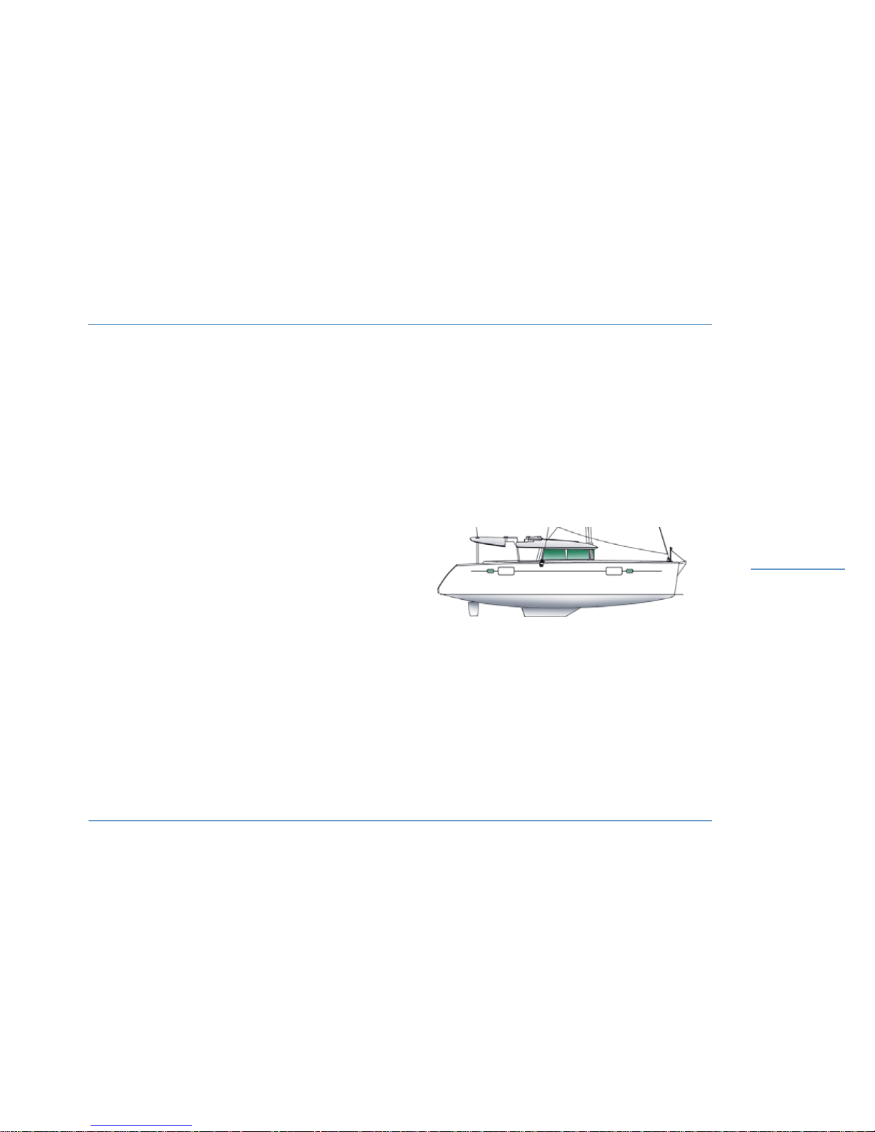
LAGOON 450
Length Over All ...................................................... 13.96 m / 45'10"
Waterline length ....................................................13.38 m / 43'11"
Beam ......................................................................... 7.84 m / 25'9"
Air draft .................................................................23.05 m / 75'62"
Keel draft ...................................................................1,30 m / 4'28"
Light displacement ......................................... 16900 kg / 37265 lbs
Full load displacement (cat. A) ........................ 22015 kg / 48543 lbs
Full load displacement (cat. B) ........................ 22150 kg / 48841 lbs
Full load displacement (cat. C) ........................ 22520 kg / 49657 lbs
Full load displacement (cat. D) ........................ 23350 kg / 51487 lbs
Maximum load (cat. A) ...................................... 5115 kg / 11279 lbs
Maximum load (cat. B) ...................................... 5120 kg / 11290 lbs
Maximum load (cat. C) ...................................... 5620 kg / 12392 lbs
Maximum load (cat. D) ..................................... 6410 kg / 14134 lbs
Water capacity ............... 2 x 175 l + 2 x 175 l (option) / 2x46 US gal
Fuel oil capacity.......................................... 2 x 500 l / 2x132 US gal
Refrigeration unit capacity .. 130 l + 130 l (optional) + 80 l (optional)
....................34 US gal + 34 US gal (optional) + 21 US gal (optional)
BATTERY CAPACITY
Standard ................................................................ 3 x 140 Ah (12 V)
Optional ................................................................. 3 x 140 Ah (12 V)
Engines .................................................................2 x 110 Ah (12 V)
Generator ....................................................................110 Ah (12 V)
Engine power ....................................................................2 x 40 HP
CE CATEGORY Maximum number of persons
A..............................................................12 persons
B .............................................................14 persons
C .............................................................20 persons
D .............................................................30 persons
Bottom surface: approx. 58 m
2
/ 624 sq ft
TECHNICAL SPECIFICATIONS
SPECIFICATIONS
1
11
Page 14

Page 15

13
HULL / DECK
2.1 Construction
2.2 Careening
2.3 Deck equipment
2.4 Cockpit
2.5 Access to fly helm station
2.6 Steering system
2.7 Anchoring
2.8 Deckwash pump
2.9 Gangway
2.10 Davits
2
Page 16

LAGOON 450
HULL / DECK
14
Page 17

Motonautisme
Motonautisme ou voile
z
Motonautisme ou voile
Motonautisme
Motonautisme ou voile
z
Motonautisme ou voile
LAGOON 450
HULL / DECK
HULL / DECK
2
15
2.3 Deck equipment
z
DECK FITTINGS
The fittings on the deck of your LAGOON 450 were selected according
to quality criteria.
To keep them to their best look, a regular maintenance is necessary.
- Rinse the equipments with fresh water, particularly the stainless
steel parts.
- Lubricate the different blocks, sheaves, turnbuckles, winches, tracks
and travellers.
- Clean and polish the stainless steel parts with a chrome and stainless steel polish in case of oxidation.
z
PULPITS
Regularly rinse the stainless steel parts with fresh water.
z
LIFELINES
Inspect the metal lifelines for ‘hairy wires’.
Check for corrosion, in particular on the connections.
z
OUTSIDE WOODWORK
Regularly rinse and brush the outside woodwork with fresh water.
There are teak cleaners and brighteners on sale.
The use of a pressure washer is not advisable on teak.
2.1 Construction
The LAGOON 450 is constructed following the infusion process of a
polyester resin and a high quality anti-osmotic resin on a core of balsa
and fibreglass layers.
The hull bottoms and keels are made of monolithic laminates by infusion.
2.2 Careening
A periodical careening of your boat will keep her original performances and avoid any adhesion of marine vegetation.
The type of the water where you boat sails determines how to choose
the antifouling paint as well as how often to carry out these careenings.
Please contact a professional for advice.
WARNING
Do not let the hull’s large plexiglass windscreens come
into contact with fenders or hawsers: surface damage
would be irreparable.
Page 18
LAGOON 450
HULL / DECK
16
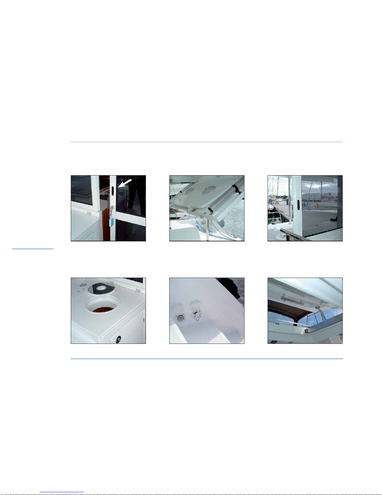
DECK EQUIPMENT
ENTRANCE DOOR
LOCKING SYSTEM
BIN LOCKER
COCKPIT TABLE
STORAGE SPACE
SHOWER IN TRANSOM
OPENING SERVING
HATCH
SUNROOF
Page 19

Motonautisme
Motonautisme ou voile
z
Motonautisme ou voile
Motonautisme
Motonautisme ou voile
z
Motonautisme ou voile
2
LAGOON 450
HULL / DECK
HULL / DECK
17
z
PLEXIGLAS
To protect the surface of your windows in plexiglas, avoid any contact
with alcohols, tanning creams, sand and all abrasive products generally speaking.
- Rinse the plexiglas with fresh water, do not use solvents.
- Brighten up with a soft rag soaked with a gentle cleaning product.
- Use polish paste to remove scratches.
2.4 Cockpit
z
ACCESS DOORS
The sliding door is fitted with a mechanism allowing its locking in an
open position. A latch on the door jamb allows its locking from inside
the saloon.
z
COCKPIT TABLE
The cockpit table is removable. It can be stored in the fly bridge
roof.
z
BIN LOCKER
A bin locker with top opening is located on the saloon port side
entrance.
z
SERVING HATCH
The cockpit is fitted with an opening serving hatch.
While sailing, please lock the serving hatch either in the open or
closed position.
z
SWIM LADDER
A stainless steel swimming ladder is located on the starboard
transom. The boat may optionally be fitted with a second swimming
ladder.
z
SHOWER
A shower supplied with hot and cold water is located on the starboard
side of the transom.
z
SUNROOF
The sunroof, located on the fly bridge roof port side can be opened
from the cockpit.
It enables you to optimize the cockpit airing and offers a better field of
vision when manoeuvring in reverse.
WARNING
Be careful when opening the locker located under
the flying bridge roof.
WARNING
For safety’s sake, always sail with the ladder up and
kept in position.
RECOMMENDATION
While sailing, block the sliding door locking it.
Page 20
LAGOON 450
HULL / DECK
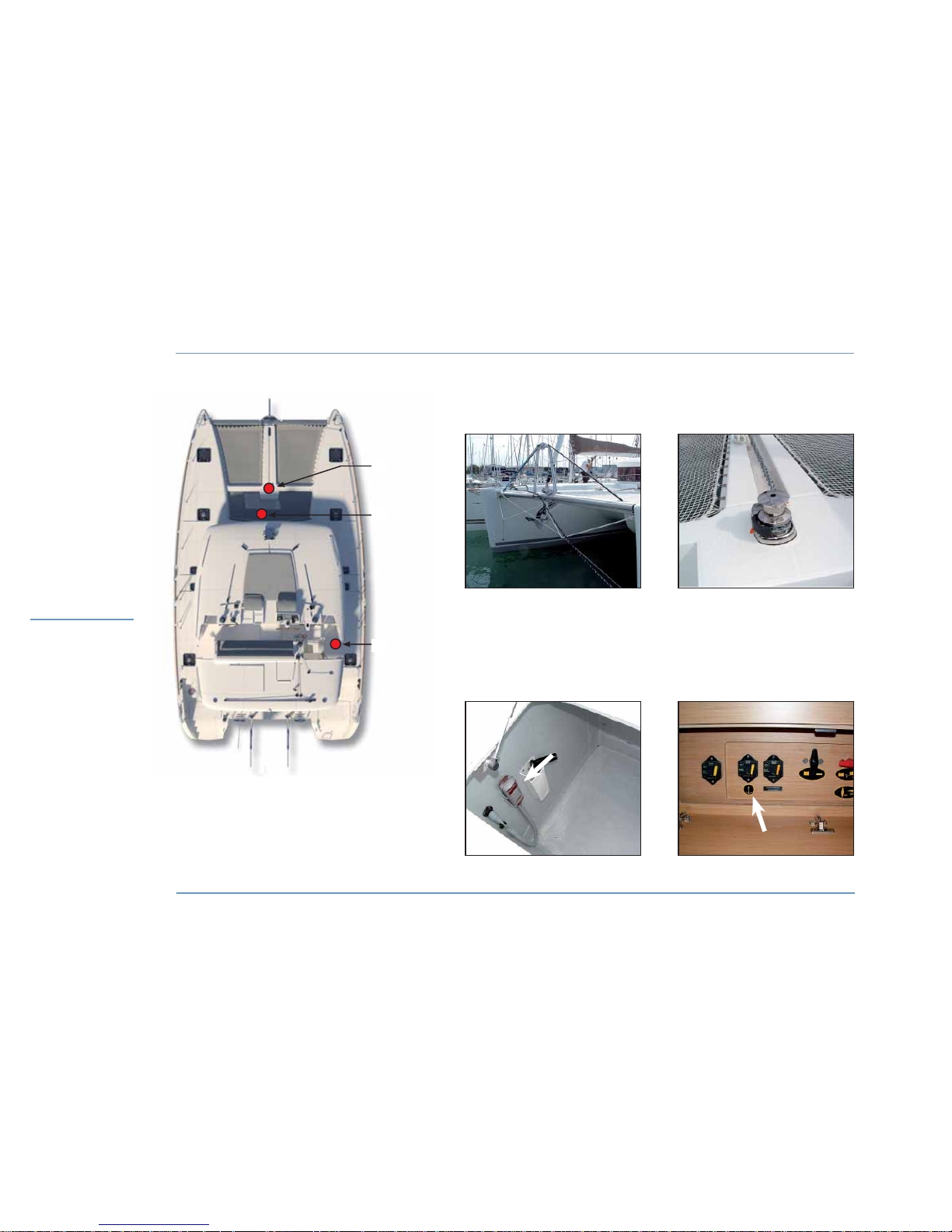
STROP - ELECTRIC WINDLASS
18
1 - Electric windlass.
2 - Control of the electric windlass.
3 - Windlass automatic breakers.
STROP CIRCUIT ELECTRIC
WINDLASS
AUTOMATIC BREAKER
OF THE WINDLASS
CONTROL
OF THE WINDLASS
2
1
3
Page 21
Motonautisme
Motonautisme ou voile
z
Motonautisme ou voile
Motonautisme
Motonautisme ou voile
z
Motonautisme ou voile
2
LAGOON 450
HULL / DECK
HULL / DECK
19
2.5 Access to the fly helm stations
Two stairs, one on the starboard and the other on the port side, lead
you from the cockpit to the steering wheel on the flying bridge.
While sailing, pay attention to the possible movements of the boat
when using the stairs.
2.6 Steering system
The steering system is made up of steering cables (stainless steel
cables) and an aluminium quadrant.
You can reach it through the engine compartments both starboard
and port sides.
The suspended rudders are fitted with stainless steel stocks.
Only WD 40 should be used to maintain nylon ertalon or teflon
bushings.
Please refer to Chapter ‘SAFETY’ as for the emergency tiller use.
2.7 Anchoring
z
WINDLASS
The electric windlass works with the 12 V domestic batteries.
Activate the windlass using its control located in the starboard side
locker on the front deck.
If the electrical windlass does not function properly, check its fuse
under the aft starboard side cabin berth.
For the maintenance of the windlass, please refer to the manufacturer’s
guide.
z
PREPARING ANCHORING
Set the strop fastening it to the chainplates at the ends of the main
beam.
Insert the strop inside the stem anchor roller.
Make fast the strop to the central cleat when lowering the chain.
RECOMMENDATION
Before you anchor, check the type of the sea bed,
the depth of water and the strength of the stream.
RECOMMENDATION
Use the electric windlass when one or two engines
are operating.
Page 22
LAGOON 450
HULL / DECK
DECKWASH PUMP
20
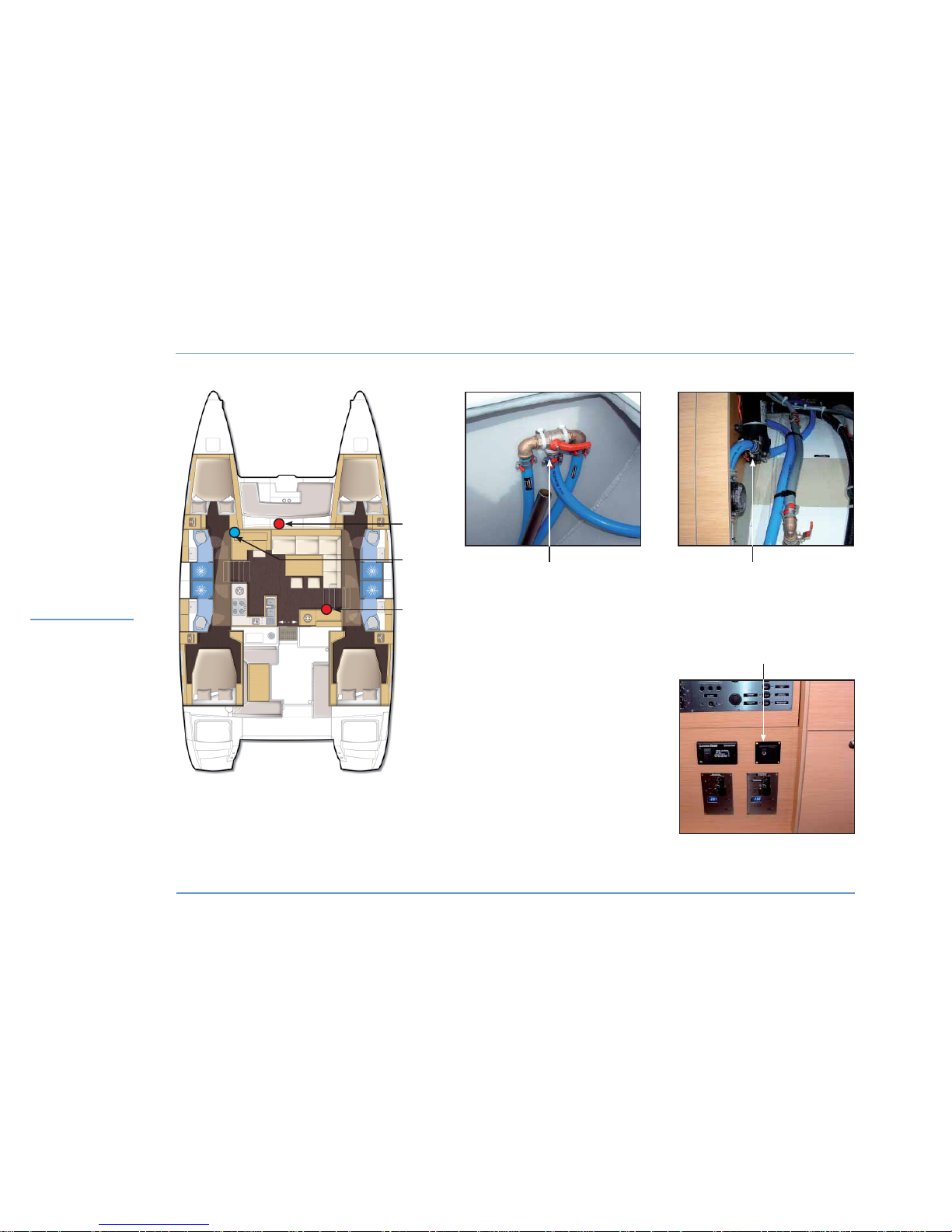
1 - Valve to select fresh water / sea water.
2 - Deckwash pump.
3 - Power switch.
1
3
2
Nota: the same layout can be observed
in the other version.
1
3
2
Page 23

Motonautisme
Motonautisme ou voile
z
Motonautisme ou voile
Motonautisme
Motonautisme ou voile
z
Motonautisme ou voile
2
LAGOON 450
HULL / DECK
HULL / DECK
21
Nota: the boat may optionally be fitted with a chain counter and with
a windlass control located on the command post.
The standard calibration zero corresponds to the position ‘anchor
ready to let it go’.
For its use and maintenance please refer to its instruction guide.
2.8 Deckwash pump (optional extra)
The deck wash pump is located in the cupboard in the port side front
cabin.
It can provide fresh or sea water coming from the tanks.
The fresh or sea water selector valve is located in the fore peak port
side locker.
Turn on the deck wash pump using its control located in the saloon
under the electrical panel.
z
ANCHORING
Have your boat head wind and without speed.
Pay out the chain while moving back slowly.
Secure the chain on the strop.
Release the chain until the strop is taut.
Pay attention to the swinging space when mooring.
z
RAISING THE GROUND TACKLE
Check the chain is properly set on the grab.
Operate the windlass setting it to the ‘upward’ position.
Slowly go near the anchor using the engine (do not use the windlass
force to winch up the boat).
Visually check the final metres until the anchor gets into contact with
the anchor fairlead.
Check the position of the anchor on the stem fitting.
Rinse the windlass and the ground tackle with fresh water after each
trip.
In case of electric failure, use the winch handle on the windlass to
raise the ground tackle.
WARNING
Windlass operations are dangerous:
- Always keep the ground takle clear and free.
- Always proceed with care, wearing gloves and
always wearing shoes.
- Make sure that nobody leans on the windlass when
operating the control.
Page 24
LAGOON 450
HULL / DECK
22
DAVITS
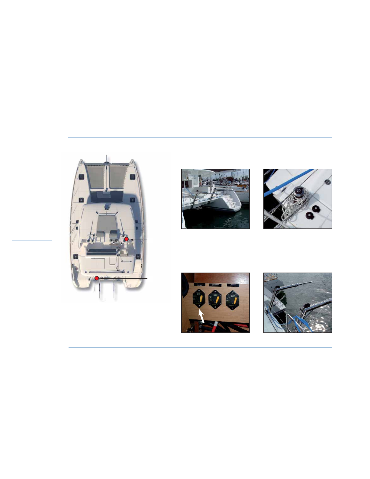
1 - Davits circuit breaker.
2 - Davits electric winch + controls.
1
2
DAVITS ELECTRIC
WINCH + CONTROLS
DAVITS
DAVITS CIRCUIT BREAKER DAVIT
BLOCKER
Page 25

2
LAGOON 450
HULL / DECK
HULL / DECK
23
2.9 Gangway (optional extra)
The boat may optionally be fitted with a foldable carbon gangway.
Remove, store and stow the gangway when sailing.
2.10 Davits (optional extra)
The boat may optionally be fitted with manual winch and davits.
An electric winch can be chosen as an option.
The winch is automatically turned on when the general cut out on
board is set to ON.
If it does not function properly, check its fuse located in the electrical
room, in the starboard aft passageway.
z
INSTALLING A TENDER ONTO THE DAVITS
After having taken away everything from the tender and removed the
cap:
- Fix the davit rope hooks to the front and rear parts of the tender.
- Lock the jammers located on the davits.
- Take the front part of the tender half way up using the cockpit
winch.
- Do the same for the rear part.
- Alternatively lift up the front part then the rear part of the tender until
it touches the davits.
z
LAUNCHING A TENDER FROM THE DAVITS
Put the water drain plug back into position in the tender.
Make fast the tender.
- Check that the jammers located on the davits are locked.
- Run the davits pennant attached to the rear of the tender around the
winch (spin at least three times around it).
- Open the jammer and slack the pennant half-way.
- Lock the jammer.
- Do the same for the front part.
- Let the tender go down alternately front and rear until it touches
water.
When sailing, remove the tender engine and store it on board.
Moor the tender considering the sea state and the route.
Put in the tender the security equipment in conformity with the
registration country of the boat.
WARNING
The davits are designed to support a maximum
load of 250 kg and a tender which is maximum 3,80
metres long.
WARNING
Do not use the gangway as a diving board.
Page 26
LAGOON 450
24
HULL / DECK
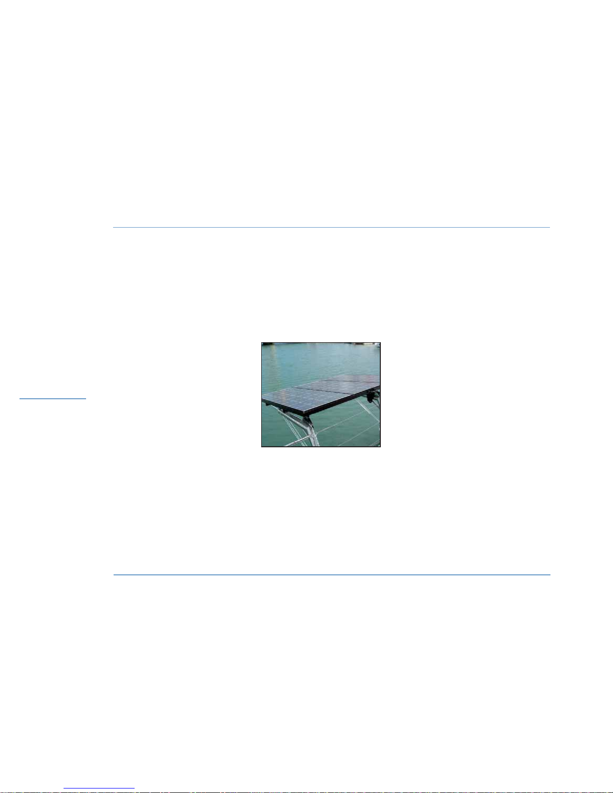
SOLAR PANELS
SOLAR PANELS
Page 27

2
LAGOON 450
25
HULL / DECK
HULL / DECK
z
SOLAR PANELS (OPTIONAL EXTRA)
The boat may optionally be fitted with solar panels.
The solar panels may fit on the davits (optional extra).
WARNING
Nobody should be on board or under the tender
during manoeuvres carried out with the davits.
Tie up the tender during manoeuvres.
Page 28

Page 29

27
RIGGING / SAILS
3.1 Sailing
3.2 Standing rigging
3.3 Running rigging
3.4 Sails
3
Page 30
LAGOON 450
28
RIGHTING MOMENT
RIGGING /
SAILS
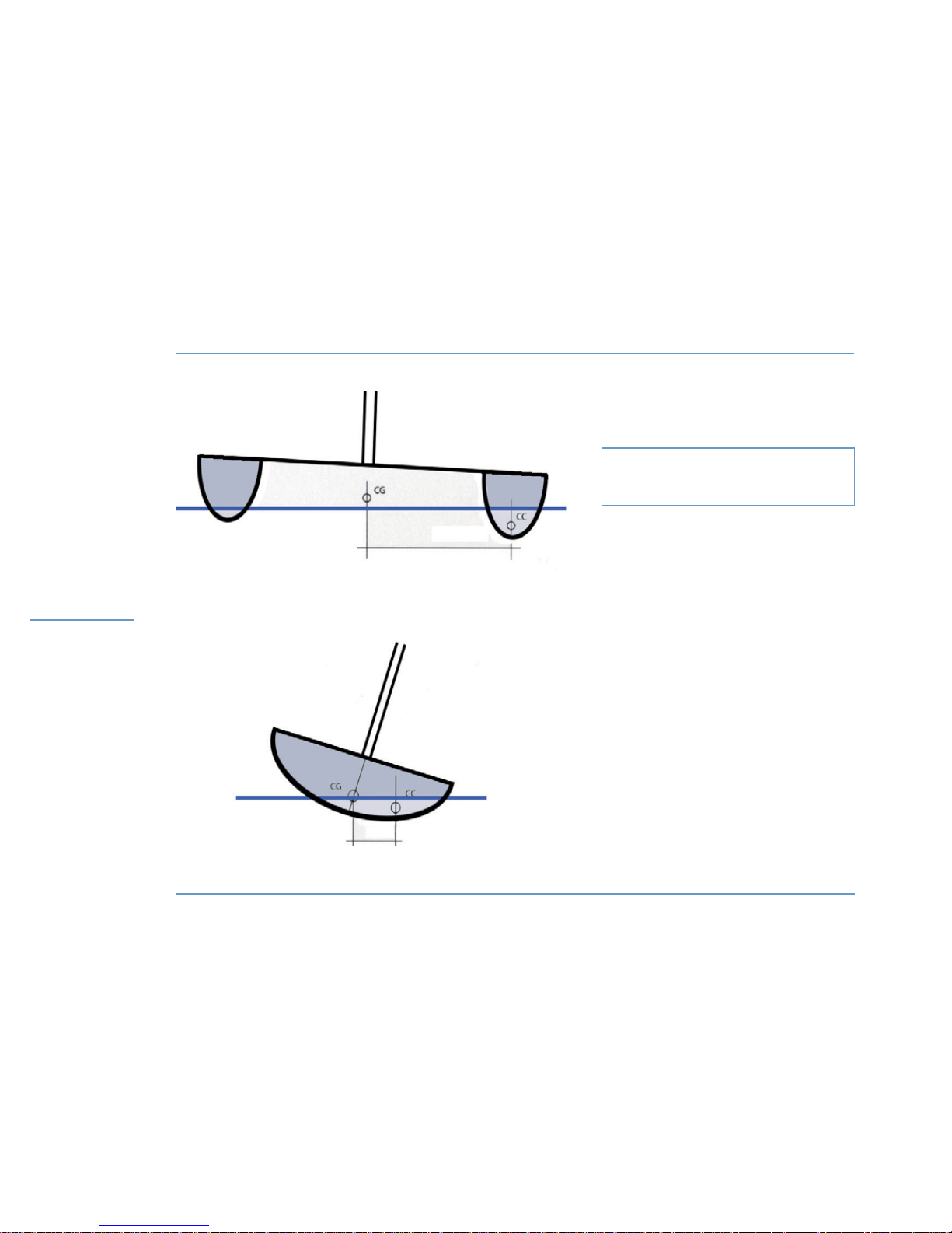
Illustration of the difference of the righting moment
existing between a 10 m monohull and catamaran.
d: distance between centre of the bottom
and centre of gravity.
RMmax: Weight of the boat x d
(RMmax: moment of maximum uprighting)
RMmax monohull : 10 tons x 0,5 metres
: 5 tons.metre
RMmax catamaran : 10 tons x 3 metres
: 30 tons.metre
CATAMARAN
Weight of the boat: 10 tons
MONOHULL
Weight of the boat: 10 tons
D: 3 metres
D: 0,5 metres
Page 31

Motonautisme
Motonautisme ou voile
z
Motonautisme ou voile
Motonautisme
Motonautisme ou voile
z
Motonautisme ou voile
LAGOON 450
29
3
RIGGING / SAILS
3.1 Sailing
z
BEWARE
A catamaran is about 6 times more resistant to heeling than a
monohull.
In naval architecture, it is referred to as uprighting moment
multiplication of the weight of the boat by the transversal distance
between the centre of gravity and the centre of flotation (or bottom).
See the illustration on the opposite page.
This fact has real consequences as for the sailing and sail trimming
of a catamaran.
The fact that the boat does not heel may mask overcanvassing, which
may be very dangerous for the crew and the boat. Therefore you must
permanently keep a close eye on the speed of the true wind, and trim
the sail surface according to the latter as a matter of priority.
The below-mentioned trims apply in a calm sea. When the sea is
brown, you shall reduce earlier by 10% as far as the speed of true
wind is concerned. And as a general rule, it is absolutely imperative to
permanently try to ease up the boat rather than to stress her.
You will always try to have the forward edges of the sails facing the
apparent wind, and to have the sail not sheeted home, so that the
airflow behind the sail may be laminar, that is to say so that it may go
off the aft part of the sail without any disruption.
In case you shouldn’t follow the recommendations below, it might be
dangerous for the boat and the crew, and, in case of an accident, the
manufacturer’s responsibility would not be involved.
z
TRIMMING WHEN CLOSE HAULED (between 75 and 50° of true wind)
Wind force given in apparent wind
- From 0 to 16 knots: full sail; sheet traveller 30 cm above the centre
line of the boat, mainsail sheeted with a slightly open leech (boom on
the centre line of the boat).
The genoa is trimmed so that it skims the spreader, the genoa
traveller is set so that the angle of the genoa sheet is the continuation
of a straight line that goes through the sheet clew and the luff, at 40%
of its height.
- From 16 to 20 knots: full sail; the sheet traveller goes up 60 cm
above the centre line of the boat, mainsail sheeted with a leech a
little more open (boom always in line: therefore you must ease off the
sheet). The genoa traveller remains at the same place but the sheet
is adjusted so that the leech is 10 cm far from the spreader.
- From 20 to 26 knots: 1 reef, full genoa; the sheet traveller goes
back to 30 cm above the centre line of the boat.
The genoa traveller remains at the same place but the sheet is eased
off so that the leech is 20 cm far from the spreader.
- From 26 to 30 knots: 1 reef, 75% of the genoa; the sheet traveller
goes up 60 cm above the centre line of the boat.
The genoa traveller remains at the same place or slightly goes forward
but it is adjusted so that the leech makes a propeller shape where the
upper part let some air go off in increases of wind.
- From 30 to 36 knots: 2 reefs, 60% of the genoa; the sheet traveller
is back 30 cm above the centre line of the boat, the sheet is 50 cm
eased off and the boom is leeward.
RIGGING /
SAILS
Page 32
LAGOON 450
30
SAILS
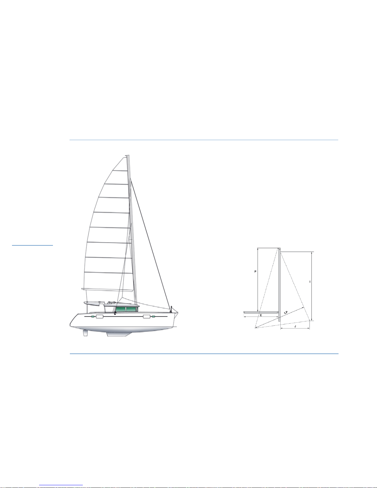
Sails
Sail surface close hauled .....................................134 m2 / 1071 sq.ft
Fully battened mainsail .......................................82.50 m2 / 888 sq.ft
Square top mainsail (optional extra) .........................85 m2 / 915 sq.ft
Furling genoa .....................................................51.80 m2 / 557 sq.ft
Spinnaker (optional extra) ....................................190 m2 / 2044 sq.ft
Gennaker (optional extra) .....................................105 m2 / 1130 sq.ft
I ..............................................................................17,746 m / 58’3’’
J ............................................................................ 4,698 m / 15’5’’
P...........................................................................17,653 m / 57’11’’
E ...............................................................................6.630 m / 21’9”
RIGGING /
SAILS
Page 33

Motonautisme
Motonautisme ou voile
z
Motonautisme ou voile
Motonautisme
Motonautisme ou voile
z
Motonautisme ou voile
LAGOON 450
31
RIGGING / SAILS
3
- From 36 to 45 knots: 2 reefs, genoa 40%. The sheet traveller is
on the centre line of the boat, the sheet is 1 metre eased off and the
boom is leeward.
The genoa traveller goes slightly forward, the sheet is eased off in
order to open wide in gusts.
- From 45 to 55 knots: 3 reefs only (or try sail, or lying to), the
traveller is on the centre line of the boat, the sheet is 1 metre eased
off and the boom is leeward.
The boat would be more at ease scudding in such a weather.
- Over 55 knots: lying to, sea anchor, or preferably scudding.
z
TRIMMING WHEN DOWN WIND (between 75 and 130° of true wind)
- From 0 to 23 knots: full sail; the traveller can be set at different
places ranging from 1 metre off the centre line of the boat to the end
of the track, depending on the angle of the wind, the sheet is eased
off so that the boom may be leeward and 50 cm far from the traveller
in dead calm then up to 2 metres when the wind strengthens.
In all the cases, you will avoid having more than one batten chafing
against the upper shroud, in the fairest points of saling.
The genoa is eased off in order to have its average front edge facing
the apparent wind.
- From 23 to 28 knots: 1 reef, full genoa. The trimmings are similar.
- From 28 to 33 knots: 2 reefs, 80% of the genoa. The trimmings
remain similar.
- From 33 to 38 knots: 2 reefs, 60% of the genoa. The trimmings
remain similar.
- From 38 to 45 knots: 3 reefs (or mainsail lowered and slightly more
genoa), genoa 40%. The trimmings remain similar.
- Fom 45 to 55 knots: mainsail lowered, genoa 40 to 30% quite
hardened in order to avoid flapping.
- Over 55 knots: scudding, depending on the sea, you will set
mooring ropes from one transom extension to the other one in order
to reduce the speed of the boat.
These figures are given for reference only and are to be adapted
regarding external conditions.
z
SQUARE TOP MAINSAIL
WARNING
If there is a radar aerial on the mast, keep an eye on
the genoa when you put about or gybe in order to
avoid any risk of damage.
WARNING
A cruising square top mainsail is more powerful than
a standard mainsail.
Short en the sails earlier, depending on the wind
conditions.
RIGGING /
SAILS
Page 34
LAGOON 450
32
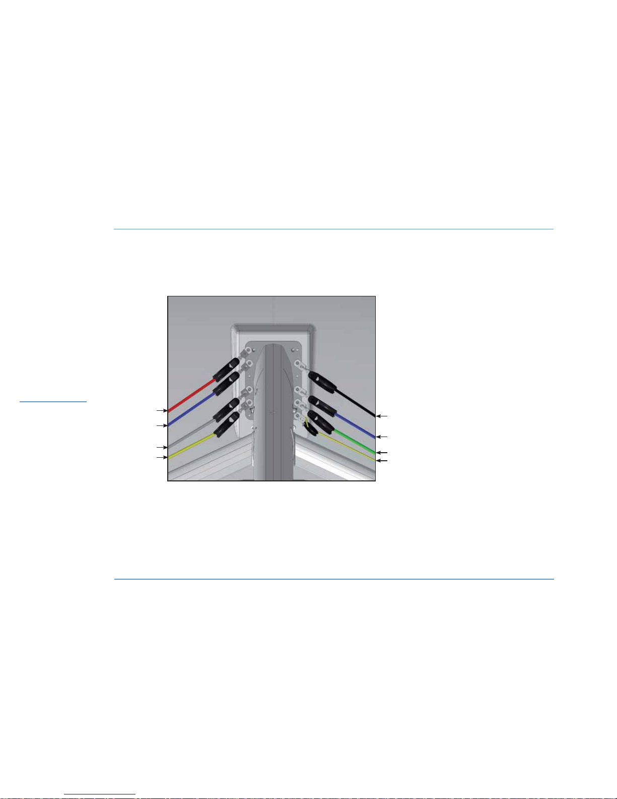
RIGGING PLAN - MAST FOOT
1 - Spinnaker halyard.
2 - Jib halyard.
3 - Mainsail topping lift.
4 - Reef 1.
5 - Mainsail halyard.
6 - Reef 3.
7 - Reef 2.
8 - Mainsail lowering rope.
RIGGING /
SAILS
5
1
2
3
4
6
7
8
Page 35
Motonautisme
Motonautisme ou voile
z
Motonautisme ou voile
Motonautisme
Motonautisme ou voile
z
Motonautisme ou voile
LAGOON 450
33
3
RIGGING / SAILS
3.2 Standing rigging
The LAGOON 450 has been adjusted by the shipyard and by the mast
manufacturer when first masting.
The cables stretch a little during the first sailings. Therefore it is
advisable to have the mast inspected and adjusted by a specialist.
Before you put out to sea, it is essential to make sure that the standing
rigging is in good condition: inspect the gooseneck, turnbuckles, and
check the condition of the shrouds.
To hoist a crew member up to the top of the mast, use the man
hoisting halyard.
Belay the crew member with a bowline on the bosun’s chair ring (do
not use snap shackle or shackle).
RECOMMENDATION
Any intervention on the standing rigging comes
within a specialist remit.
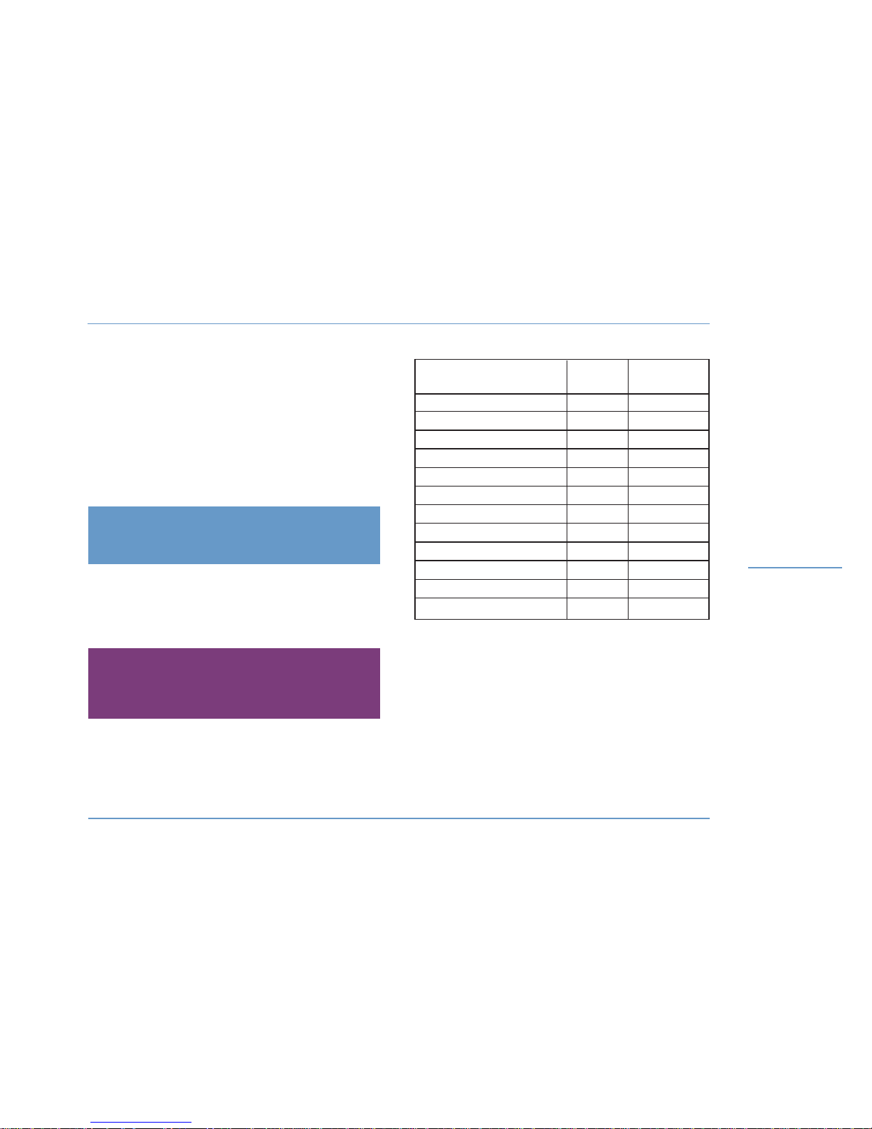
Description of the ropes length (m) diametre (mm)
Genoa halyard
44 12
Genoa sheet 19 x 2 14
Main halyard 67 12
Mainsail topping lift 46 12
Mainsheet 34 14
Mainsail traveller adjustment 19 x 2 10
Reef 1 (automatic) 32 14
Reef 2 (automatic ) 40 14
Reef 3 (manual) 36 14
Sheet + spinnaker guy 18 x 2 12
Gennaker sheet 29 14
Spinnaker / gennaker halyard 48 12
WARNING
The man hoisting halyard which is the only one to be
authorized for this purpose, is only meant to hoist a
crew member up to the top of the mast.
RIGGING /
SAILS
Page 36
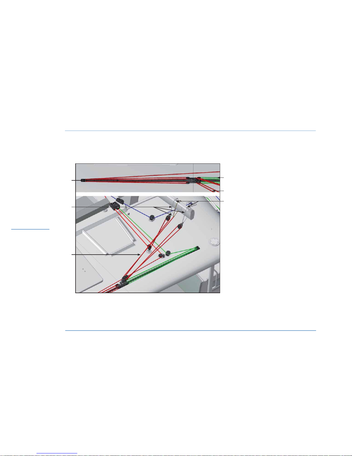
LAGOON 450
34
RUNNING RIGGING - MAINSAIL CIRCUIT
RIGGING /
SAILS
1 - Mainsail traveller adjustment / starboard.
2 - Mainsail sheet.
3 - Stropes.
4 - Mainsail traveller adjustment / port side.
5 - Strope fastening.
2
3
1
4
5
2
Page 37

Motonautisme
Motonautisme ou voile
z
Motonautisme ou voile
Motonautisme
Motonautisme ou voile
z
Motonautisme ou voile
LAGOON 450
35
RIGGING / SAILS
3
3.4 Sails
z
STANDARD MAINSAIL
To hoist the standard mainsail:
- Point your boat into wind with engine in gear.
- Make sure that the mainsheet is eased off and the reefs are free.
- Open the jammer.
- Hoist the sail being careful for the battens not to get jammed in the
lazy-jacks.
- Make fast the halyard with the jammer.
- Trim the mainsail according to the wind and sea conditions.
To lower the standard mainsail:
- Haul up.
- Tighten the topping lift.
- Slacken off the halyard, lower the mainsail then furl it.
- Tighten the sheet.
z
REEFING A SAIL
On each reef, you will also find a stopper on the leech and on the
tack.
- Move the mainsail closer to the eye of the wind, using the wheel or
the traveller.
- Check the main sheet.
- Pick up the lift again.
- Slip the halyard.
- Tighten the tack pendant of the reef concerned till the lowest
possible point, then close the jammer.
- Repeat the same maneuver with the reef tack stopper.
- Hoist the main sail home and shut the locker.
- Slip the lift.
3.3 Running rigging
The mainsail, genoa and staysail sheets, the topping lift, the reefing
lines, the mainsail and spinnaker halyards, the control lines for the
main traveller are led back to the manoeuvre station.
z
SHEET WINCHES AND MANOEUVRE WINCHES (MANUAL OR ELECTRIC)
(OPTIONAL EXTRA)
The circuit breakers for the electric winches are located in the
electrical room, in the starboard aft passageway.
WARNING
Refer to the manufacturer’s instructions to remove
the winches and put them back.
Improper refitting may result in accidents (for
example: kick of the crank handle).
RECOMMENDATION
Have at least 3 turns on the winch.
Electrical winches generate an extremely powerful
force and you should use them with much care.
Never force when you find a jamming point.
When using the winches, keep your hands away.
After use, shut the switch covers.
RIGGING /
SAILS
Page 38
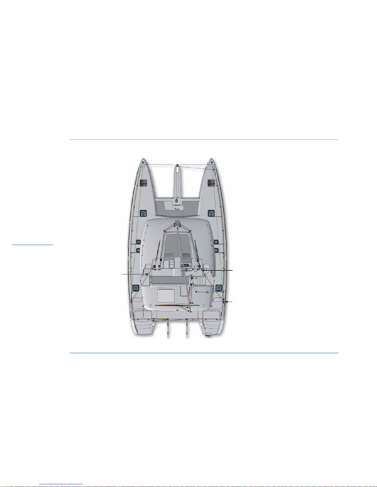
LAGOON 450
36
RIGGING /
SAILS
1 - Spinnaker guy.
2 - Gennaker / spinnaker sheet.
3 - Gennaker / spinnaker block.
1
2
3
RUNNING RIGGING SPINNAKER - GENNAKER
Page 39

Motonautisme
Motonautisme ou voile
z
Motonautisme ou voile
Motonautisme
Motonautisme ou voile
z
Motonautisme ou voile
LAGOON 450
37
RIGGING / SAILS
3
REEF SHAKING OUT
- Make the mainsail closer to the eye of the wind, either steering the
boat or using the traveller.
- Ease off the mainsheet.
- Tighten the topping lift.
- Ease off the tack and leech reef pendants.
- Hoist the mainsail, then close the jammer.
- Slacken off the topping lift.
z
CRUISING SQUARE TOP MAINSAIL
The cruising square top mainsail halyard is lashed on the eyelet of the
sail, not on the headboard traveller.
The square top will be properly set automatically once the sail is
hoisted up.
FITTING OF THE MAINSAIL CRUISING SQUARE TOP SYSTEM
Refer to the drawing on the opposite page.
- Remove the pin of the headboard car (mark A).
- Make the 2 strand tackle as per the drawing on the opposite page.
- Put back the headboard car pin (mark A), adding the sheave.
The length of the headboard line is adjusted to the right dimension for
a new sail at the sailmaker’s.
The lashing (mark D) makes possible to make up for the possible
lengthening of the rope due to ageing.
Nota: this system is patented by the INCIDENCES sailmaker.
z
ROLLER FURLING GENOA
Hoist the genoa before you get under way, taking advantage of a
windless period of time.
- Secure the head.
- Secure the halyard to the slide-swivel.
- Secure the tack to the drum and secure the sheets.
- Insert carefully the bolt rope into the hole, hoist the sail and take
care you do not tear it.
- Haul the halyard taut enough but sway it up less than a sail on a
standard stay.
- Hoist it until the horizontal creases disappear (the tension of the luff
shall be adjusted after a few sea trips).
- Pull on the line from the cockpit to furl the genoa.
WARNING
A cruising square top mainsail has a more important
power than a standard mainsail.
Shorten the sail earlier depending on the wind
conditions.
RIGGING /
SAILS
RECOMMENDATION
Hand pre roll the drum to set the genoa furling line
on it.
Pay attention to the drum furling direction: the
sacrificial strip of the genoa shall be wrapped
outside.
Never force when you furl or unfurl the head sails in
case it seizes. Make sure a halyard is not caught in
the roller furler.
Page 40
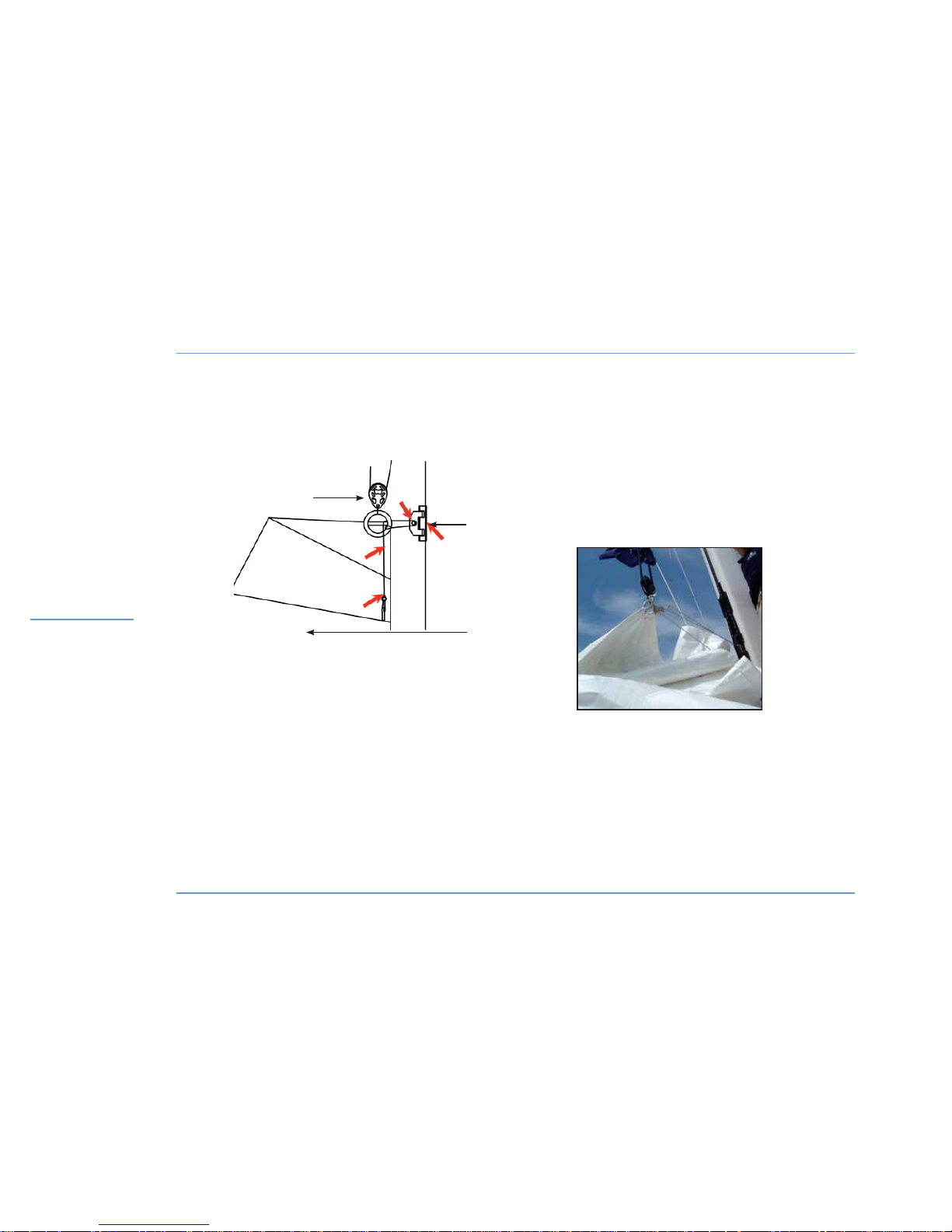
LAGOON 450
38
RIGGING /
SAILS
CRUISING SQUARE TOP MAINSAIL
1
C
A
D
2
1 - Headboard traveller.
2 - Halyard block (to be fastened onto the headboard eye).
3 - Cruising square top mainsail.
3
FASTENING OF THE RUISING
SQUARE TOP MAINSAIL
Page 41

LAGOON 450
39
RIGGING / SAILS
3
RIGGING /
SAILS
z
GENNAKER
Remove the forward lifelines when using the gennaker (risk of
damage).
Before getting under the way, take advantage of a windless period of
time and hoist the gennaker.
- Secure the swivel to the gennaker headboard.
- Secure the furling system to the tack clew.
- Put the furling system to the boomsprit with a snap shackle.
- Secure the halyard to the headboard swivel.
- Hoist the gennaker.
Use the furling system line to furl or unfurl the gennaker.
Gennaker sheets:
- Secure the sheets to the gennaker clew.
- Have the sheets go on the outside of the stay and shrouds and above
the guardrails.
- Make fast the sheet leading blocks to the chainplates.
- Reroute the sheets to the genoa sheet winches.
WARNING
In some sailing trims, the gennaker may hide the
fore navigation lights.
WARNING
Unrig the gennaker when not in use (risk of being UV
damaged and inadvertently unfurled).
Page 42

Page 43

41
4.1 Saloon - Galley
4.2 Lighting
4.3 Portholes - Deck hatches
4.4 Window blinds
ACCOMMODATIONS 4
Page 44
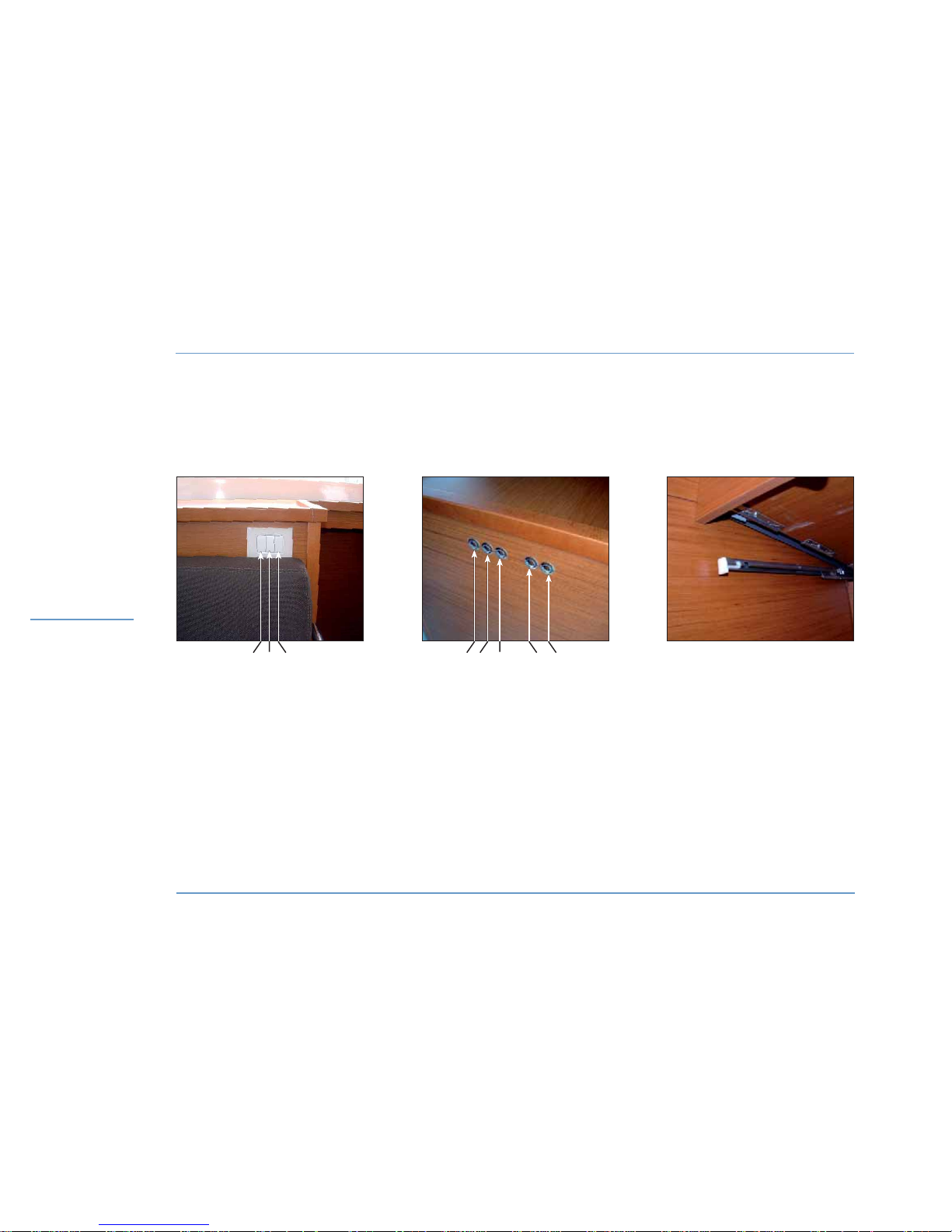
LAGOON 450
42
LIGHTINGS - DRAWER
ACCOMMODATIONS
LIGHTING SWITCHES
DIRECT - SALOON STARBOARD
REMOVING
THE DRAWER LEVER + RAILS
LIGHTING SWITCHES
ENTRANCE STARBOARD
1 - Starboard front.
2 - TV set up / down (optional fitting).
3 - Port side front.
4 - Saloon starboard.
5 - Saloon front.
6 - Lighting indirect saloon.
7 - Lighting indirect - cockpit.
8 - Lighting - cockpit.
1 543 872 6
Page 45

Motonautisme
Motonautisme ou voile
z
Motonautisme ou voile
Motonautisme
Motonautisme ou voile
z
Motonautisme ou voile
LAGOON 450
43
4
ACCOMMODATIONS
ACCOMMODATIONS
4.1 Saloon - Galley
z
FLOORBOARDS
The floorboards can be lifted up to have access to the different
technical components on board.
z
TABLE
You can switch the saloon and cockpit tables around.
An optional fitting allows to turn the saloon table into a double berth
after having changed the legs and added extra cushions.
z
DRAWERS
The drawers in the galley have an automatic closing function.
Gently push the drawer till the movement ends itself.
These drawers can be removed pushing on the levers on each side,
under the rails.
When you reassemble it, clip the drawer before you push it back.
4.2 Lighting
There are many ways of lighting the saloon, directly or indirectly, depending on the atmosphere you want to create.
After having turned on the 12 V circuit on board and the lighting circuit
using the switch located on the electrical panel next to the starboard
entrance of the saloon, you can turn the light on.
RECOMMENDATION
To avoid premature ageing of the floorboards (dents,
scratches) it is recommended to keep them as clean
as possible and to remove shoes inside the boat.
Page 46
LAGOON 450
44
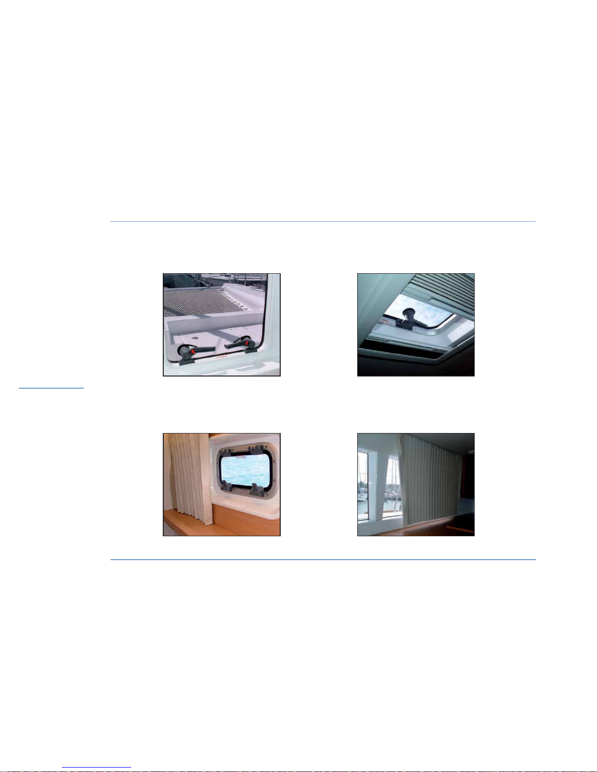
PORTHOLES - HATCHES - WINDOWS
ACCOMMODATIONS
LOCKING OF THE DECK HATCH
AND THE PORTHOLES
SHUTTER - SIDE WINDOW
BLIND AND MOSQUITO
SCREEN ON DECK HATCH
SHUTTER - SALOON
Page 47

LAGOON 450
45
4.3 Portholes - Deck hatches
The portholes and deck hatches have locking systems to keep them
in a closed position.
At anchor, intermediate opening position allows the ventilation of the
boat.
The deck hatches are fitted with a blind and mosquito screen system
that can be used even when the hatch is open.
Their handling shall be done carefully.
4.4 Window blinds
All the windows have blinds.
The opening hatches of the aft cabin(s) are also fitted with blinds.
4
ACCOMMODATIONS
ACCOMMODATIONS
RECOMMENDATION
Pull and push the blinds carefully.
Take care to fasten them when they are fitted with
the relevant systems.
Page 48

Page 49

47
5.1 Refrigerators - Conservator - Icemaker
5.2 Microwave oven
5.3 Oven, hotplate
5.4 Dishwasher
5.5 Washer dryer
5.6 Television
5.7 Air conditioning system
5.8 Heating system
UTILITY
ABOARD
5
Page 50
LAGOON 450
48
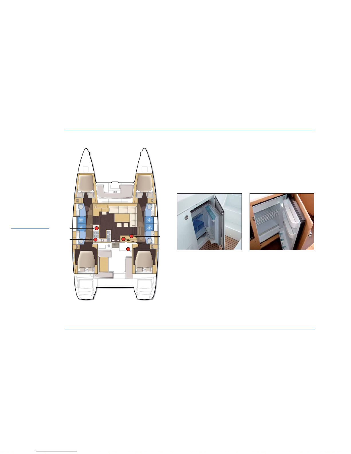
REFRIGERATORS - CONSERVATOR - ICEMAKER - MICROWAVE OVEN
UTILITY
ABOARD
5
3
4
1 - Refrigerator.
2 - Microwave oven (optional extra).
3 - 110 V - 220 V selection panel.
4 - Refrigerator / conservator - saloon (optional extra).
5 - Refrigerator / icemaker - cockpit (optional extra).
2
1
Nota: the same layout can be observed
in the other version.
REFRIGERATOR -
COCKPIT (OPTIONAL)
REFRIGERATOR -
SALOON
Page 51

Motonautisme
Motonautisme ou voile
z
Motonautisme ou voile
Motonautisme
Motonautisme ou voile
z
Motonautisme ou voile
LAGOON 450
49
5
UTILITY ABOARD
5.1 Refrigerators - Conservator -
Icemaker
The boat standard features include a 130 l refrigerator located in the
galley.
It may optionally be fitted with a conservator (110 l) or another refrigerator (130 l) located in the cupboard in the saloon starboard entrance.
The boat may also be fitted with an optional refrigerator (80 l) or an
icemaker located in the aft cockpit.
Once the general 12 V on board circuit has been powered, you can
turn on the power for the different devices using the cold group switch
located on the electrical panel located on the starboard side of the
saloon.
z
ICEMAKER USE
The icemaker requires 220 V.
It is supplied with water through the fresh water circuit.
- Check that its circuit breaker has been powered in the electrical
room (in the cupboard in the starboard aft passageway).
POWER SUPPLY
Select the power supply source (generator or supply shore socket)
using the left hand selector on the 110 V - 220 V selector board (in the
cupboard at the saloon starboard side entrance).
Nota: the icemaker circuit is fitted with a filter (access under the starboard side aft passageway floor).
Have this filter changed regularly.
For the use and maintenance of the refrigerator and freezer, please
refer to their instruction guides.
5.2 Microwave oven (optional extra)
Depending on the fitting out, a microwave oven, located in the galley,
can be provided (over the hob).
- Check the microwave plugging.
- Check that the sockets switches have been powered on the selection panel located in the saloon starboard entrance.
POWER SUPPLY
Select the power supply source (generator or supply shore socket)
using the left hand selector on the selector board at the saloon starboard entrance.
For the use and maintenance of the microwave oven, please refer to
its instruction guide.
RECOMMENDATION
Defrost then drain off the refrigerators and the
conservator before cutting the 12 V circuit on
board.
UTILITY
ABOARD
Page 52
LAGOON 450
50
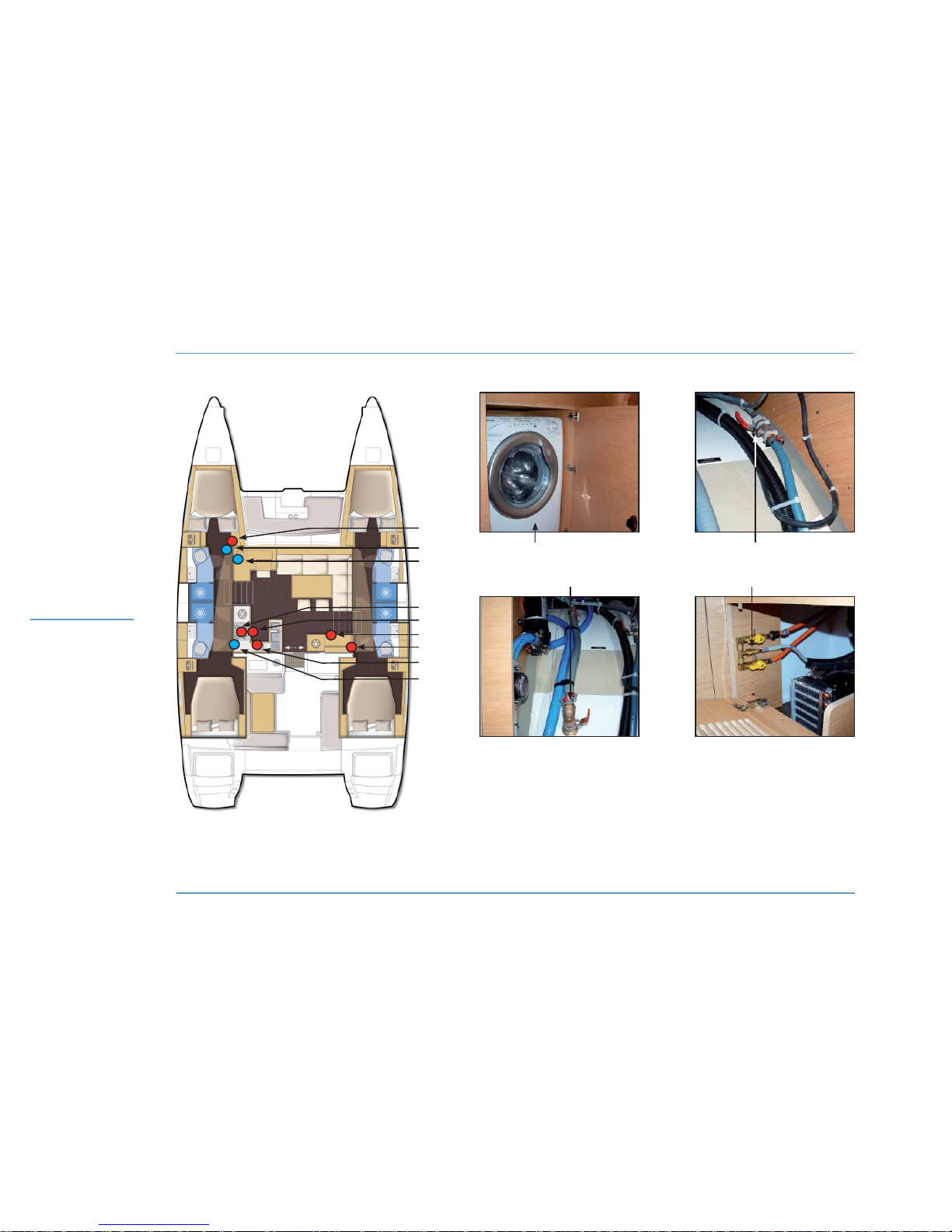
OVEN - HOTPLATE - DISHWASHER - WASHER DRYER
2 5
31
UTILITY
ABOARD
Nota: the same layout can be observed
in the other version.
1 - Washer dryer (optional extra).
2 - Outlet valve of the washer dryer.
3 - Supply valve of the washer dryer.
4 - Oven + hotplate.
5 - Gas valves.
6 - 110 V - 220 V selection panel.
7 - Circuit breakers panel.
8 - Dishwasher (optional extra).
9 - Supply valve of the dishwasher.
6
1
2
3
4
5
8
7
9
Page 53

Motonautisme
Motonautisme ou voile
z
Motonautisme ou voile
Motonautisme
Motonautisme ou voile
z
Motonautisme ou voile
LAGOON 450
51
5
UTILITY ABOARD
5.5 Washer dryer (optional extra)
The boat standard features include a washer-dryer located in a cupboard in the port side front cabin.
It is supplied with water coming from the fresh water system.
Check that the relevant fresh water inlet valve is open in the front port
side passageway cupboard.
Drainage is made through the valve located in the front port side passageway cupboard.
- Check that its circuit breaker has been powered in the electrical
room (in the cupboard in the starboard aft passageway).
SUPPLY
Select the power supply source (generator or supply shore socket)
using the left hand selector on the 110 V - 220 V selector board (in the
cupboard at the saloon starboard side entrance).
For the use and maintenance of the washer-dryer, please refer to its
instruction guide.
5.3 Oven, hotplate
The boat is standard fitted with a gas cooking hob.
The gas valves are located in the cupboard at the left of the oven.
The gas cartridges are located in the port side cockpit locker.
5.4 Dishwasher (optional extra)
The boat is fitted with an optional dishwasher located in the galley.
It is supplied with water coming from the fresh water system.
Drainage is made through the sink drainage system.
Check that the relevant fresh water inlet valve is open in the plumbing
room (aft port side passageway).
- Check that the relevant circuit breaker has been powered in the
electrical room (in the cupboard in the starboard aft passageway).
SUPPLY
Select the power supply source (generator or supply shore socket)
using the left hand selector on the 110 V - 220 V selector board (in the
cupboard at the saloon starboard side entrance).
For the use and maintenance of the dishwasher, please refer to its
instruction guide.
RECOMMENDATION
Shut the gas valves and the regulator tap when you
do not use the hob.
RECOMMENDATION
The washing machine shall not work while you are
sailing.
UTILITY
ABOARD
Page 54
LAGOON 450
52
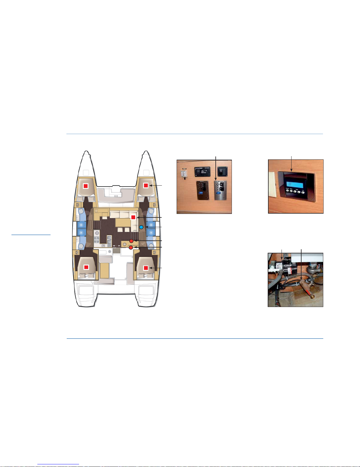
TELEVISION - AIR CONDITIONING
1 - Air conditioning unit.
2 - Sea water pump / Air conditioning.
3 - Selection panel / Air conditioning.
4 - Television.
5 - Air conditioning control.
6 - Seawater supply valve /
Air conditioning.
UTILITY
ABOARD
1
1
4
3
2
3
Nota: the same layout can be observed
in the other version.
1
5
2
6
Page 55

Motonautisme
Motonautisme ou voile
z
Motonautisme ou voile
Motonautisme
Motonautisme ou voile
z
Motonautisme ou voile
LAGOON 450
53
5
UTILITY ABOARD
5.6 Television (optional extra)
The saloon may optionally be fitted with an electric TV lift.
The owner's cabin may also be fitted with an optional TV.
The TV sets are supplied with a converter.
After having turned on the 12 V on board circuit:
- Press the switch located next to the starboard companion ladder in
order to make the TV go up or down.
Check carefully that nothing may block the TV trap.
Set the TV on its initial position when sailing.
An antenna booster is located next to the pillar, behind the back of
the saloon seating.
For the use and maintenance of the television, please refer to its instruction guide.
5.7 Air conditioning system
(optional extra)
The boat may be fitted with an optional reversible air conditioning system.
The air conditioning units are located in the cabins and in the saloon.
You will find vents in every cabin and in the saloon.
Before you start the system:
Open the sea water circulation system (suction valve in the sump and
direct drainage).
SUPPLY
Select the power supply source (generator or supply shore socket)
using the right hand 110 V - 220 V selector board located in the cupboard at the saloon starboard entrance.
Check that the pumps and air conditioning groups are turned on on
the circuit breakers located in the electrical room in the aft starboard
passageway.
Start the air conditioning unit in the desired area, select hot or cold
and set the temperature using its control.
Regularly clean the filters on the conditioned-air systems and sea water suction valves.
For the drainage, use and maintenance of the air conditioning system,
please refer to its instruction guide.
UTILITY
ABOARD
Page 56
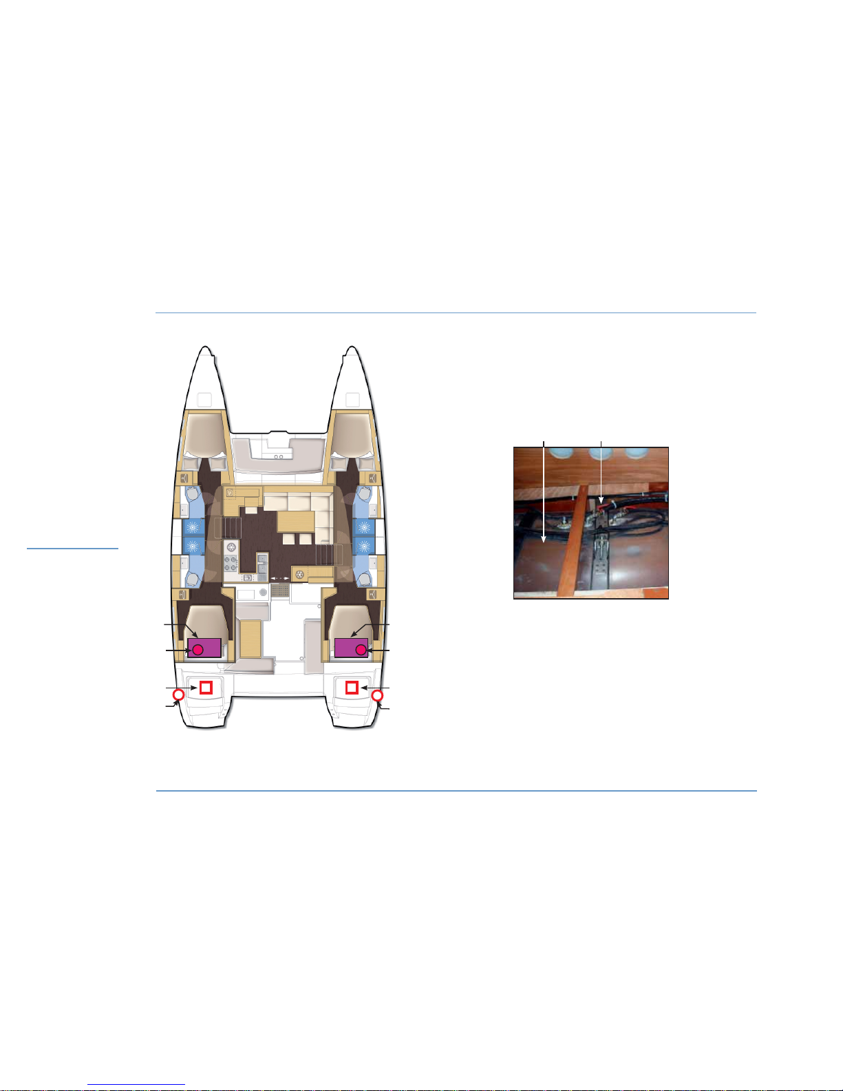
LAGOON 450
54
HEATING SYSTEM
1 - Fuel tanks.
2 - Fuel valves.
3 - Boilers.
4 - Boiler exhaust outlet.
3
1
1
1
3
2
22
UTILITY
ABOARD
Nota: the same layout can be observed
in the other version.
4
4
Page 57

Motonautisme
Motonautisme ou voile
z
Motonautisme ou voile
Motonautisme
Motonautisme ou voile
z
Motonautisme ou voile
LAGOON 450
55
5
UTILITY ABOARD
UTILITY
ABOARD
5.8 Heating system (optional extra)
The boat may optionally be fitted with a diesel heating system with
circulating water.
The boilers are located in the engine compartments both starboard
and port sides.
- Check the fuel valve is open (access on the tanks in the starboard and
port side aft cabins).
- Start each boiler then set the temperature using their controls.
For the use and maintenance of the heating system, please refer to its
instruction guide.
WARNING
Be careful not to set any fender in front of the
heating boiler exhaust outlets.
Page 58

Page 59

57
6.1 Bilge pump system
6.2 Grey waters
6.3 Black waters
6.4 Fresh water
6.5 Watermaker
WATER
SYSTEMS
6
Page 60
LAGOON 450
58
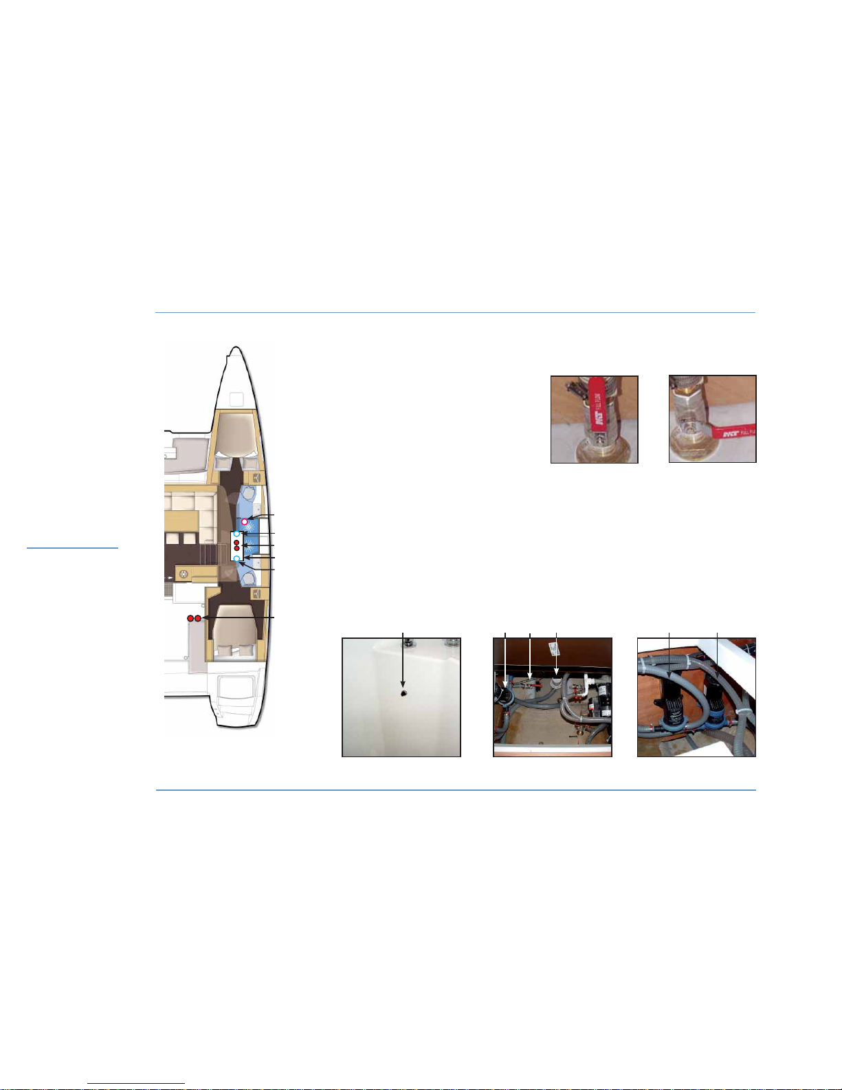
BILGE PUMP SYSTEM - GREY WATERS
WATER SYSTEMS
1 - Shower pump switch.
2 - Front / aft compartment outlet valve.
3 - Electric bilge pumps.
4 - Hull sump.
5 - Manual bilge pumps.
6 - Shower drain valve.
Each hull has the same components.
Nota: each valve in the boat is identified.
1
3
5
4
SEA-COCK
OPEN
SEA-COCK
CLOSED
1 3 3 6
Nota: the same layout can be observed
in the other version.
2
2
3
2
Page 61

Motonautisme
Motonautisme ou voile
z
Motonautisme ou voile
Motonautisme
Motonautisme ou voile
z
Motonautisme ou voile
LAGOON 450
59
6
WATER SYSTEMS
WATER SYSTEMS
6.1 Bilge pump system
A main sump is under the floorboard of each hull.
The fore and aft compartments are linked to these sumps by a bilge pipe
and a valve (access under the floorboards).
Each well is emptied by three bilge pumps:
- A manual cockpit pump.
- An electric pump with manual release from the electrical board.
- An electric pump with manual and automatic release located in the
well.
6.2 Grey waters
The grey waters (sink, washbasins) directly flow out via sea-cocks with
valves.
Please note: a valve is closed when its handle is perpendicular to the
hose and it is open when its handle is in line with the hose.
Grey waters coming from the showers are emptied through pumps
located under the floors of the starboard and port passageways.
The pumps are switched on from the 12 V domestic circuit.
In order to empty the showers, use the pump switch located on the
wet room cupboard.
RECOMMENDATION
Regularly check the valves and sea-cocks for proper
operation and watertightness.
Regularly make sure the filters and strainers on the
draining system are clean.
RECOMMENDATION
Always keep the bilge pumps switched on the
automatic mode with alarm.
We advise you to test the bilge pumps every time
you put out to sea.
RECOMMENDATION
When mooring in a harbour, if possible, use the
sanitary facilities provided by the port authority.
In some harbours or countries, wastewater disposal
is forbidden. You will then have to use the waste
tank.
WARNING
The bilge pump system is not designed to provide
buoyancy to the boat in case of damage.
The bilge pump system is designed to drive out the
water being either sea spray or leaks but absolutely
not the water coming through a hole in the hull, this
hole being the result of a damage.
Page 62
LAGOON 450
60
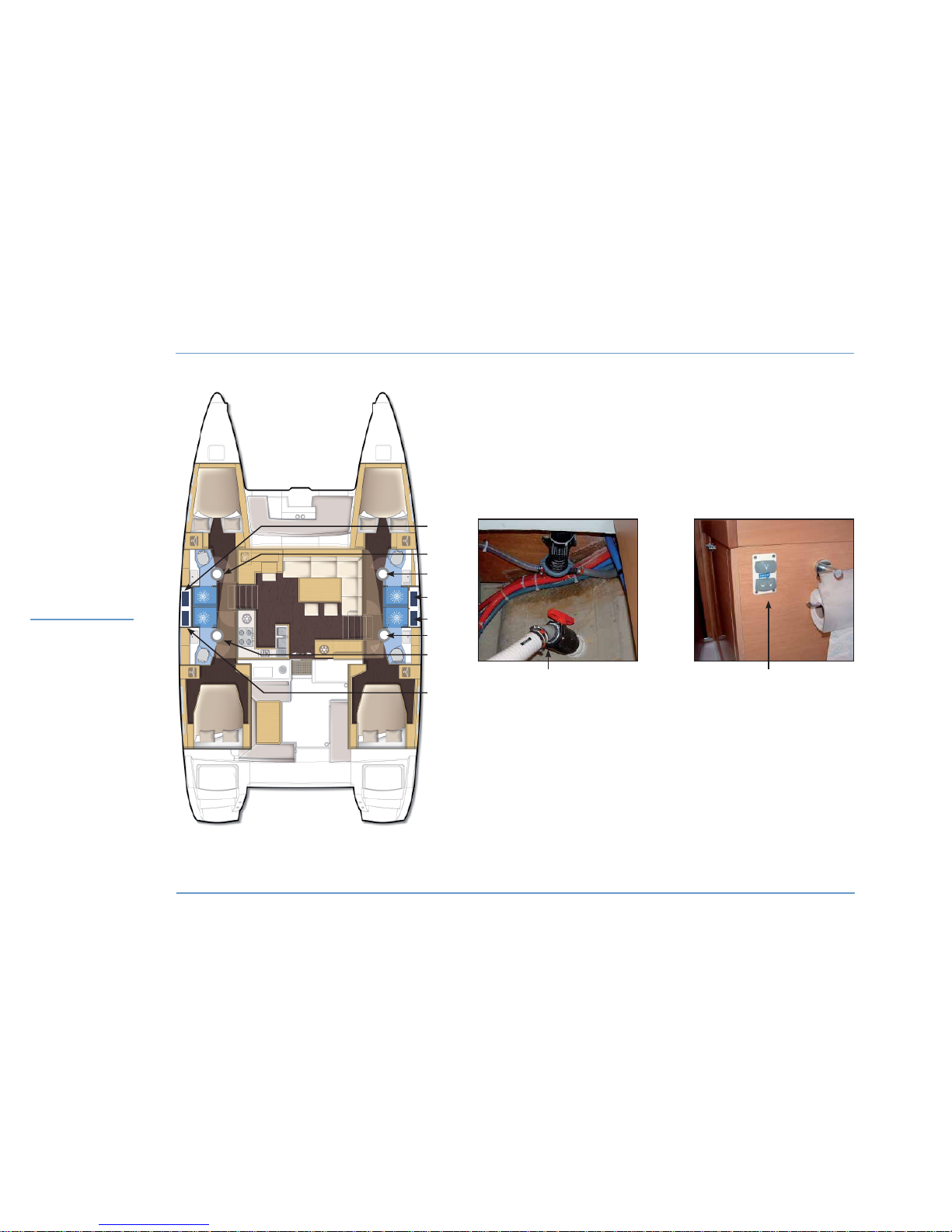
BLACK WATERS
WATER SYSTEMS
1 - Holding tank.
2 - Drain valve on hull.
3 - Switches of the electric toilets.
2 3
1
1
1
1
2
2
Nota: the same layout can be observed
in the other version.
2
2
Page 63

Motonautisme
Motonautisme ou voile
z
Motonautisme ou voile
Motonautisme
Motonautisme ou voile
z
Motonautisme ou voile
LAGOON 450
61
6
WATER SYSTEMS
WATER SYSTEMS
6.3 Black waters
The boat is fitted with manual toilets and a holding tank in the port aft
washroom, as standard equipments.
She may be fitted with optional electric toilets and holding tanks in all
the washrooms.
z
USE OF THE MANUAL TOILETS
Open the water inlet and drain valves.
To empty the bowl:
- Set the control lever of the pump slantwise (FLUSH) and operate the
pump.
To dry the bowl:
- Set the lever back vertical (DRY) and operate the pump.
In order to avoid clogging the toilets, use absorbent paper only and
pump until the emptying hose is completly empty.
Regularly rinse the toilets with fresh water.
Close the valves after each use.
z
USE OF THE ELECTRIC TOILETS
The electric toilets are rinsed with sea water.
The electric pump, its filter and the supply valve are located in the
washroom cabinet.
- Switch on the 12 V domestic circuit.
- Open the water inlet and drain valves.
One of the switches next to the toilets makes possible a water intake
cycle and a water outlet cycle.
The second switch makes possible to carry out a rinse cycle.
Rinse the toilets with fresh water and regularly clean the filters.
Close the valves after each use.
For the use and maintenance of the electric toilets, please refer to
their instruction guide.
z
USE OF THE HOLDING TANKS
Tanks can be reached through the wet rooms.
Make sure the drain valve of the tank is closed in order to avoid any
inadvertent discharge (the valve is closed when the handle is perpendicular to the hose).
Tank drainage:
- In an authorized area, open the drain valve.
- In a marina equipped with an organic waste suction system, fit the
suction hose into the tank through the deck filler.
- Start the pump of the suction system.
Regularly rinse the holding tank.
The tanks shall be emptied when the boat is berthed in negative temperatures.
WARNING
Use the suction systems in marinas to empty your
holding tank. In order to respect environment, do
not discharge your holding tank near the shore.
Page 64
LAGOON 450
62
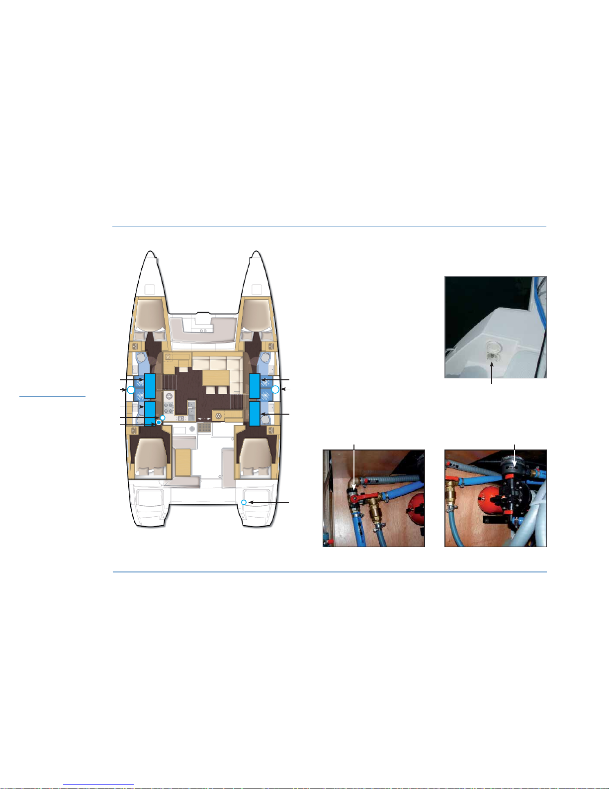
FRESH WATER
WATER SYSTEMS
2
1
2
4 5
1 - Port / Starboard forward tank.
2 - Deck filler.
3 - Aft tanks (optional extra).
4 - Valves for the selection
of the tanks.
5 - Pressure water pump.
6 - Shore fresh water supply.
6
5
Nota: the same layout can be observed
in the other version.
3
1
3
4
6
Page 65

Motonautisme
Motonautisme ou voile
z
Motonautisme ou voile
Motonautisme
Motonautisme ou voile
z
Motonautisme ou voile
LAGOON 450
63
6
WATER SYSTEMS
WATER SYSTEMS
6.4 Fresh water
z
FRESH WATER TANKS
The boat standard features include two 175 l tanks.
The tank selector valve is located in the plumbing room in the port
side aft passageway.
To prevent any handling mistake, never fill the water and fuel tanks at
the same time.
Two front filling caps (starboard and port sides) allow the tanks to be
filled up.
During filling, avoid handling contaminants near the fillers.
Open and close the filler caps with the right key.
Check the filler cap seals for condition during filling.
Never insert the water filling hose deep down into the system in order
to prevent any over-pressure in the systems.
Please note: the capacity of the fresh water tank(s) indicated on the
page ‘SPECIFICATIONS’ may be not completely usable depending on
the trim and load of the boat.
z
PRESSURE WATER PUMP
The water unit is located in the plumbing room in the port side aft
passageway.
Its starting is done by using a switch on the electrical panel.
z
WATER GAUGE
Watch the water level in the tanks using the gauge located on the
electrical panel (in the cupboard in the saloon starboard entrance).
To switch from one tank to the other, press the "Water" button.
z
SHORE FRESH WATER SUPPLY
The shore fresh water inlet valve is located in the starboard aft transom.
To use the marina fresh water:
- Connect the shore supply.
- Set the pressure water pump switch to ‘OFF’.
RECOMMENDATION
Never operate the water system equipment when
the valves are closed or when the tanks are empty
(the electrical equipment may be damaged).
Check the different water filters for condition.
RECOMMENDATION
When you leave the boat unattended, systematically
disconnect the shore fresh water supply.
RECOMMENDATION
Pay attention to the quality of the water for the
filling up.
Check if it is drinking water.
If the boat is not used for long, purify the tanks and
pipes with proper treatment.
Page 66
LAGOON 450
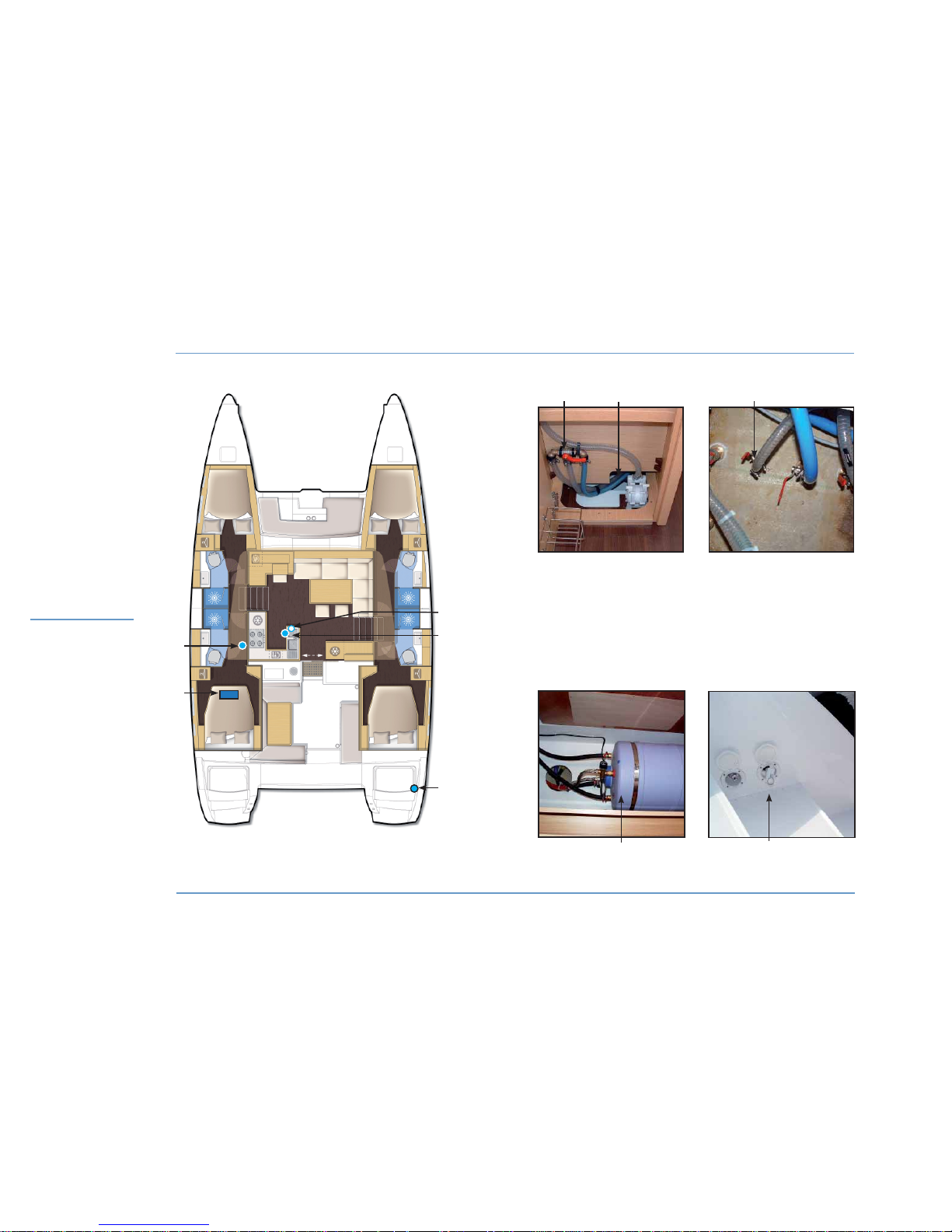
64
FRESH WATER - SEA WATER
WATER SYSTEMS
3
4
Nota: the same layout can be observed
in the other version.
1
2
5
1 - Valve to select fresh water / sea water.
2 - Foot pump.
3 - Sea water supply valve.
4 - Water heater.
5 - Shower.
5
4
1 3
2
Page 67
Motonautisme
Motonautisme ou voile
z
Motonautisme ou voile
Motonautisme
Motonautisme ou voile
z
Motonautisme ou voile
LAGOON 450
65
6
WATER SYSTEMS
WATER SYSTEMS
z
FRESH WATER / SEA WATER FOOT PUMP
The foot pump makes possible to supply a tap of the sink with fresh
water and sea water.
The 3-way fresh / sea water valve can be reached through the sink
unit.
In case of foot pump hardening, check if the water supply hose is not
blocked, or if the tap is not choked.
In the latter case, remove the tap end and clean it.
z
EXTERIOR SHOWER
A shower supplied with hot and cold water (mixing faucet) is located
on the starboard side of the transom.
It is supplied by the pressure water pump.
z
WATER HEATER
The water heater is located in the port side cabin.
It has a capacity of 60 liters.
The water heater functions automatically when the engine is on or
when set on the 110 V - 220 V circuit (generator or shore supply socket) after having activated its circuit breaker on the electrical panel in
the saloon starboard side.
The hot water temperature is pre-set using the thermostatic tap located on the water heater.
WARNING
In period of frost, do not forget to empty the cockpit
shower, even if there is someone onboard the boat.
RECOMMENDATION
When the water heater is not used, switch it off
using its 110 V - 220 V circuit.
Before you switch it on using the 110 V - 220 V
circuit, check the water heater is full of water.
Page 68
LAGOON 450
66
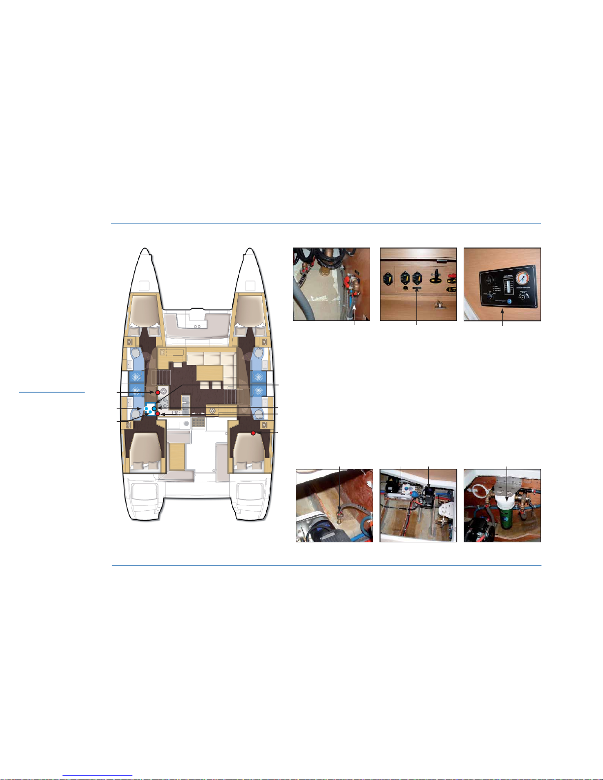
WATERMAKER
WATER SYSTEMS
1 - Watermaker.
2 - Valves to select the tanks port / starboard.
3 - Watermaker low pressure pump.
4 - Automatic breaker.
5 - Control.
6 - Sea water supply valve of the watermaker.
7 - Filter.
1 3 7
42
5
6
2
3
4
1
5
6
7
Nota: the same layout can be observed
in the other version.
Page 69

LAGOON 450
67
6.5 Watermaker (optional extra)
The boat may optionally be fitted with a water maker (100 l / hour)
located under the port side passageway floor.
OPERATION
The watermaker works either in 12 V, or in 110 V - 220 V.
Check that the relevant circuit breaker located in front of the starboard
berth has been powered.
Check its sea water supply valve is open (access under the floor of the
port side passageway).
SUPPLY
Select the power supply (12 V or 110 V - 220 V) using the selector
on the water maker control panel ( access in the port side passage
way).
Then, select the power supply source (generator or supply shore
socket) using the left hand selector on the 110 V - 220 V selector
board (in the cupboard at the saloon starboard side entrance).
Select the tank to be filled up using the relevant valve (access in the
port side passage way).
Start the water maker using its control located on its panel.
Check the level of fresh water in the tanks when the watermaker is
working.
Regularly clean the filter located under the floor of the port side passageway.
For the use and maintenance of the watermaker, please refer to its
instruction guide.
WATER SYSTEMS
6
WATER SYSTEMS
RECOMMANDATION
The watermaker shall be used exclusively in clear
waters and preferably when at anchor.
Page 70

Page 71

69
7.1 12 V circuit
7.2 Inverters
7.3 110 V - 220 V circuits
7.4 Electronics
ELECTRICITY 7
Page 72
LAGOON 450
70
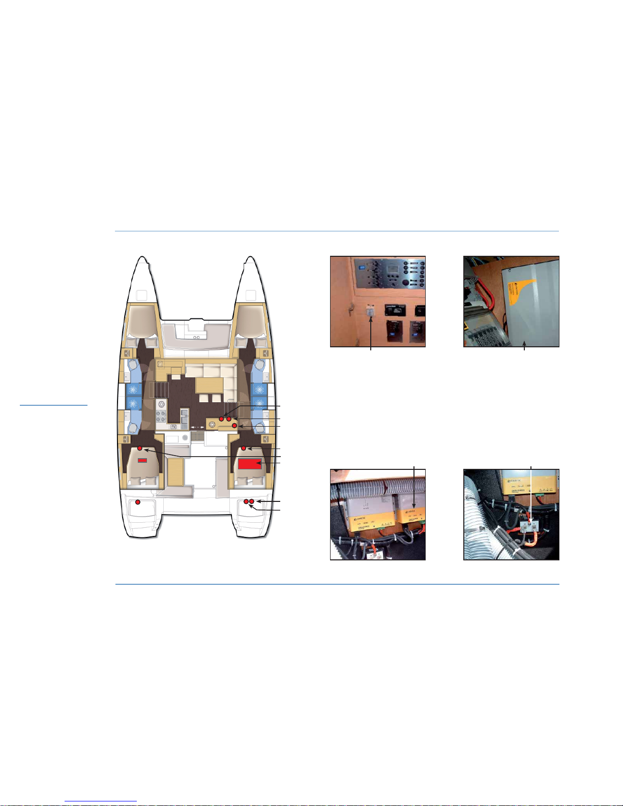
12 V ELECTRICAL PANELS - BATTERY CHARGERS - INVERTER
ELECTRICITY
5 - Cut out coupling /engine battery
port / starboard.
6 - 12 V batteries.
7 - Battery chargers.
8 - Load balancer.
1 - Electrical panel.
2 - Switch of the inverter.
3 - 12 V / 110 V - 220 V inverter.
4 - Boat and 12 V engine cutouts.
3
4
6
7
8
2
1
Nota: the same layout can be observed
in the other version.
2 3
7 8
5
Page 73

Motonautisme
Motonautisme ou voile
z
Motonautisme ou voile
Motonautisme
Motonautisme ou voile
z
Motonautisme ou voile
LAGOON 450
71
7
ELECTRICITY
ELECTRICITY
The battery chargers are located in the starboard engine
compartment.
The battery charger for the generator is located in the generator room
in the starboard locker of the fore deck.
They can be used either with the shore power supply or the
generator.
SUPPLY OF THE CHARGERS
Select the power supply source (generator or supply shore socket)
using the left hand selector on the 110 V - 220 V selector board located
in the cupboard at the saloon starboard side entrance.
The 12 V consuming appliances circuit breakers are located behind
the electrical panel.
They can be wound by pressing a black lug.
7.2 Inverters
The boat may optionally be fitted with a 12 V / 110 V - 220 V converter
located in the cupboard in the starboard aft passage way (electrical
room).
The converter switch is located at the left hand of the selection panel
(in the cupboard at the saloon starboard side entrance).
The converter supplies the galley sockets with 110 V - 220 V.
7.1 12 V circuit
The main domestic circuit is supplied in 12 V.
12 V batteries are located under the berths in the starboard and port
side aft cabins.
Board and engine cut outs are located at the front of the berths of the
starboard and port aft cabins.
For safety reasons, a coupling system for the engine batteries (cut out
located at the front of the berth in the port side aft cabin) allows the
engine to start if the relevant battery is faulty.
The generator has its own cut outs located in the starboard locker of
the front deck.
The batteries can be charged either by the engine alternator or by the
110 V - 220 V / 12 V - 60 A battery charger.
According to the lay out, the boat may optionally be fitted with an extra
110 V - 220 V / 12 V - 40 A charger.
An electricity manual is delivered with the boat.
This manual includes the diagrams and technical
explanations on the electrical systems.
Please refer to this electricity manual to get any
information that is not dealt with in this instruction
guide.
Page 74
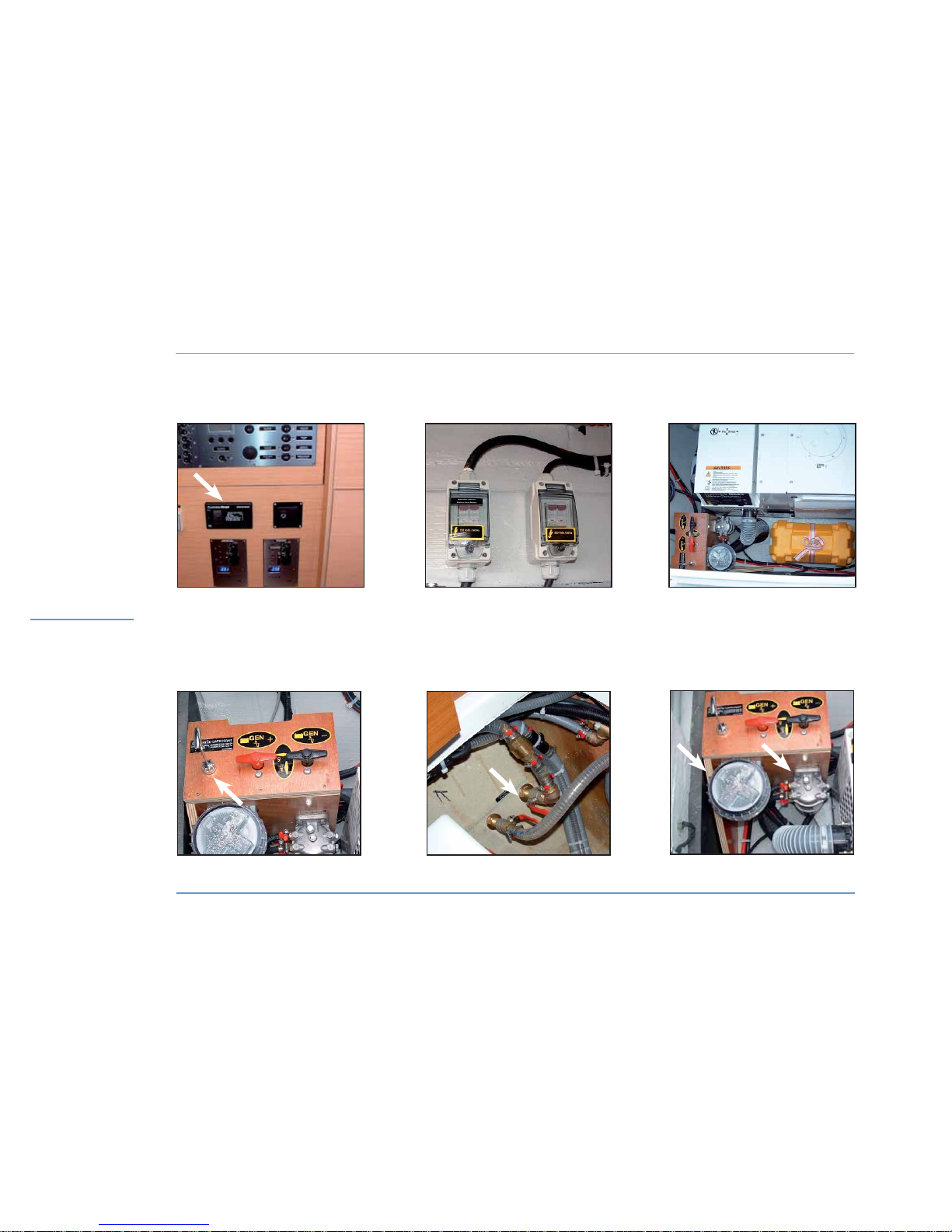
LAGOON 450
72
SHORE POWER SOCKETS - GENERATOR
ELECTRICITY
GENERATOR CONTROL
TANK / GENERATOR SELECTION
PULL ROD
GENERATOR
WATER INLET VALVE
OF THE GENERATOR
WATER FILTER + FUEL FILTER
OF THE GENERATOR
AUTOMATIC BREAKERS OF THE
SHORE POWER SOCKETS
Page 75

Motonautisme
Motonautisme ou voile
z
Motonautisme ou voile
Motonautisme
Motonautisme ou voile
z
Motonautisme ou voile
LAGOON 450
73
7
ELECTRICITY
ELECTRICITY
z
GENERATOR
The generator is located in the starboard locker of the front deck.
Its function is to re-supply the batteries via the chargers and supply
110 V - 220 V electricity on board.
OPERATION
After having turned ON the cut-outs located in the starboard locker of
the front deck, the generator can be turned on either on the generator
itself or using its control located under the electrical panel in the starboard entrance of the saloon.
- Check that the relevant sea water cooling valve is open (access
under the starboard passageway floor).
Select the fuel tank using the pull rod located next to the generator
main switch in the front deck locker.
For the use and maintenance of the generator, please refer to its instruction guide.
7.3 110 V - 220 V circuits
z
SHORE POWER SOCKETS
Both shore supply sockets are located in the starboard transom.
They supply firstly the 110 V - 220 V circuit and the battery chargers
and secondly the air conditioning system.
Before you plug in or unplug the boat / shore power supply cable,
switch off the shut off device connected to the shore supply.
Connect the boat / shore power supply cable in the boat before
connecting it to the shore supply socket.
Unplug the boat / shore supply cable on shore first.
Close the protecting cover of the shore supply socket when you do not
use the plug.
The shore power plants are protected by circuit breakers located in
the starboard engine compartment.
WARNING
Before using the shore power socket of a quay, you
must check it is operated under a 32 Ah current.
DANGER
Never let the end of the boat / shore supply cable
hang in the water; the result may be an electric field
liable to hurt or kill the swimmers nearby.
Page 76
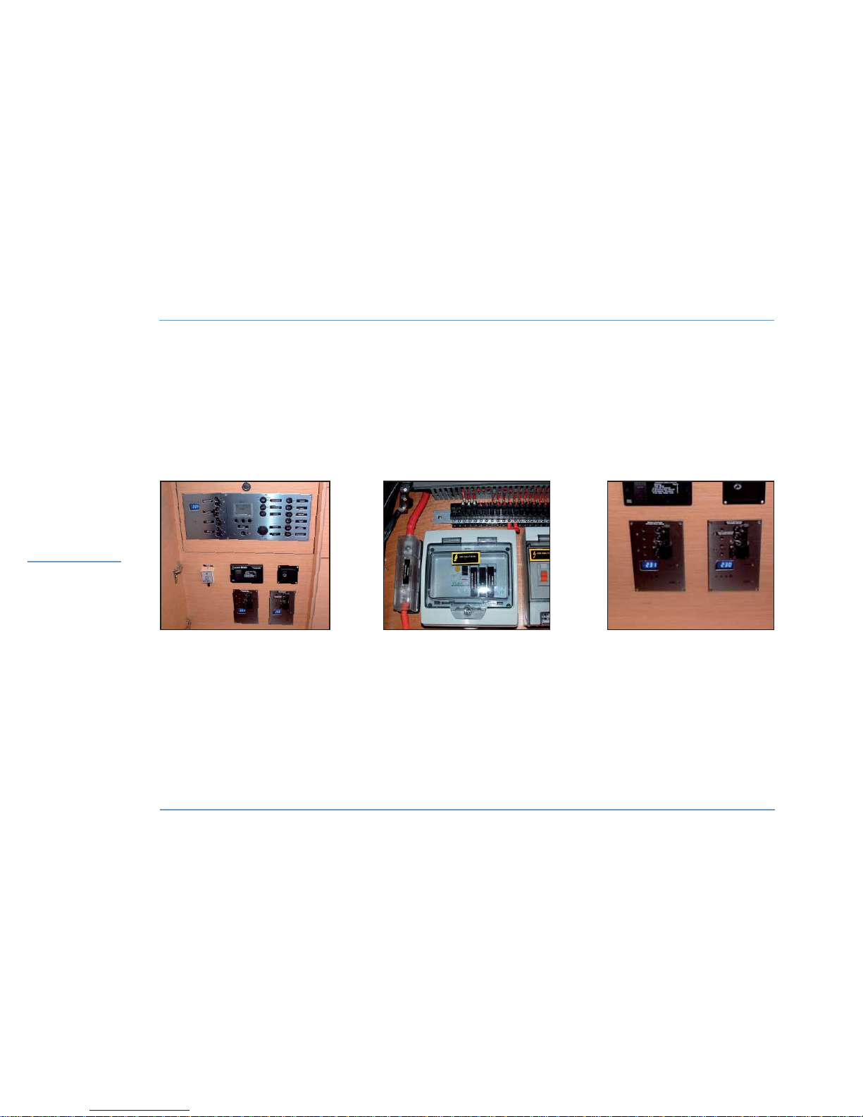
LAGOON 450
74
ELECTRICAL PANELS - SELECTORS - AUTOMATIC BREAKERS
ELECTRICITY
CONSUMING APPLIANCES
CIRCUIT BREAKERS
110 V - 220 V SUPPLY
SELECTION PANEL
ELECTRICAL PANELS
Page 77

Motonautisme
Motonautisme ou voile
z
Motonautisme ou voile
Motonautisme
Motonautisme ou voile
z
Motonautisme ou voile
LAGOON 450
75
7
ELECTRICITY
ELECTRICITY
z
CHECKING OF THE 110 V - 220 V CONSUMING APPLIANCES
SELECTION PANEL (in the cupboard at the saloon starboard entrance):
The panel is composed of selectors allowing to choose the electrical
power source for the different 110 V - 220 V consuming appliances
on board.
LEFT-HAND SIDE SELECTOR:
- allows to use the air conditioning powered by a 110 V - 220 V current
coming from the generator or from the shore power.
RIGHT-HAND SIDE SELECTOR:
- allows to use the appliances requiring a 110 V - 220 V current coming from the generator, the shore power or the inverter.
z
USE OF THE 230 V POWERED APPLIANCES
SWITCHING ON THE APPLIANCES
In order to be able to use the 110 V - 220 V powered appliances
(washing machine, watermaker, etc), it is advisable:
Make sure that the outlet automatic breaker is switched OFF on the
110 V - 220 V selection panel.
- Switch on the 110 V - 220 V source (start the generator or connect a
shore power socket to shore). Select this source on the selection panel
so that this source supplies the boat (110 V - 220 V electrical selection
panel) or turn on the inverter for the outlets.
- Push the automatic breakers of the outlets to be used on the electrical
panel.
Then start the appliance with its own controls.
To start 110 V - 220 V elements, wait for 10 to 15 seconds between
the start up of each new component (in order to allow the generator
to become stabilized and be able to give the power necessary for the
starting up).
STOPPING THE 110 V - 220 V POWERED APPLIANCES
To stop the 110 V - 220 V powered appliances (washing machine, etc.)
it is advisable to do as follows:
- Stop the appliance with its own controls.
To stop 110 V - 220 V elements, wait for 10 to 15 seconds between
the stop of each new component (in order to allow the generator to
become stabilized).
- Turn OFF the automatic breakers of the outlets on the electrical panel.
- Turn to OFF the 110 V - 220 V source selector (generator or shore
power) or turn off the inverter.
- Stop the generator or disconnect the shore power socket.
RECOMMENDATION
Keep an eye on the charge of the batteries when you
use the inverter.
WARNING
Before you turn the 110 V - 220 V source selector
to OFF, make sure no other appliance is working
(danger of an electric arc that would destroy
the changeover switch and risk of damaging the
generator).
Page 78
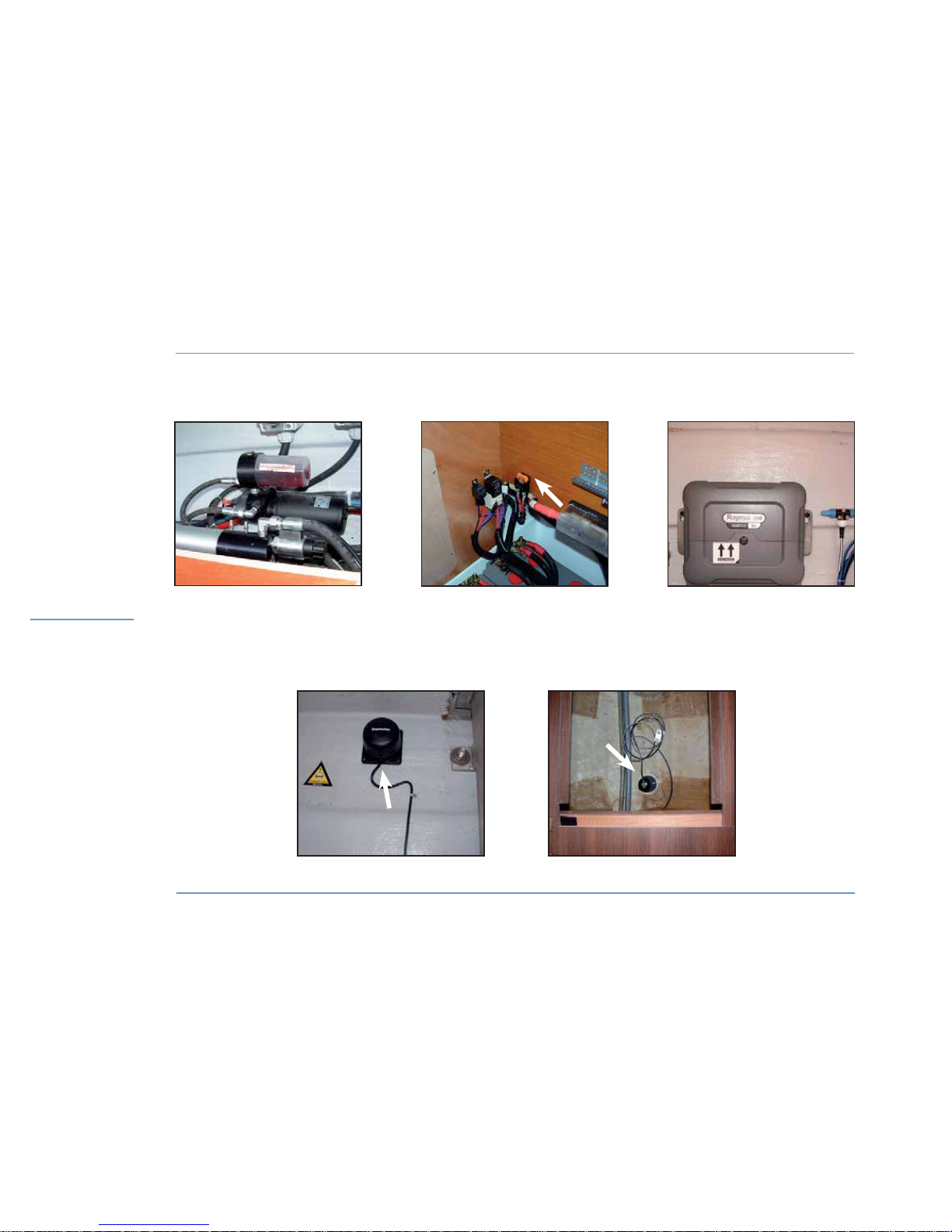
LAGOON 450
76
ELECTRICITY
ELECTRONICS
ACCESS TO
THE AUTOMATIC PILOT
AUTO PILOT FUSE
CALCULATOR
SPEEDO LOG
AUTOMATIC PILOT COMPASS
Page 79

LAGOON 450
7
ELECTRICITY
77
ELECTRICITY
7.4 Electronics
The boat may be fitted with an optional electronic pack and different
navigation aid accessories.
For the use and maintenance of all these components, please refer to
their instruction guides.
The ram, the auto pilot and the calculator are located in the starboard
engine compartment.
The auto pilot ram is located under the starboard aft berth.
The compass is located in the port side engine hold.
The speedo log (optional fitting) is located under the floor in the port
side front cabin.
Page 80
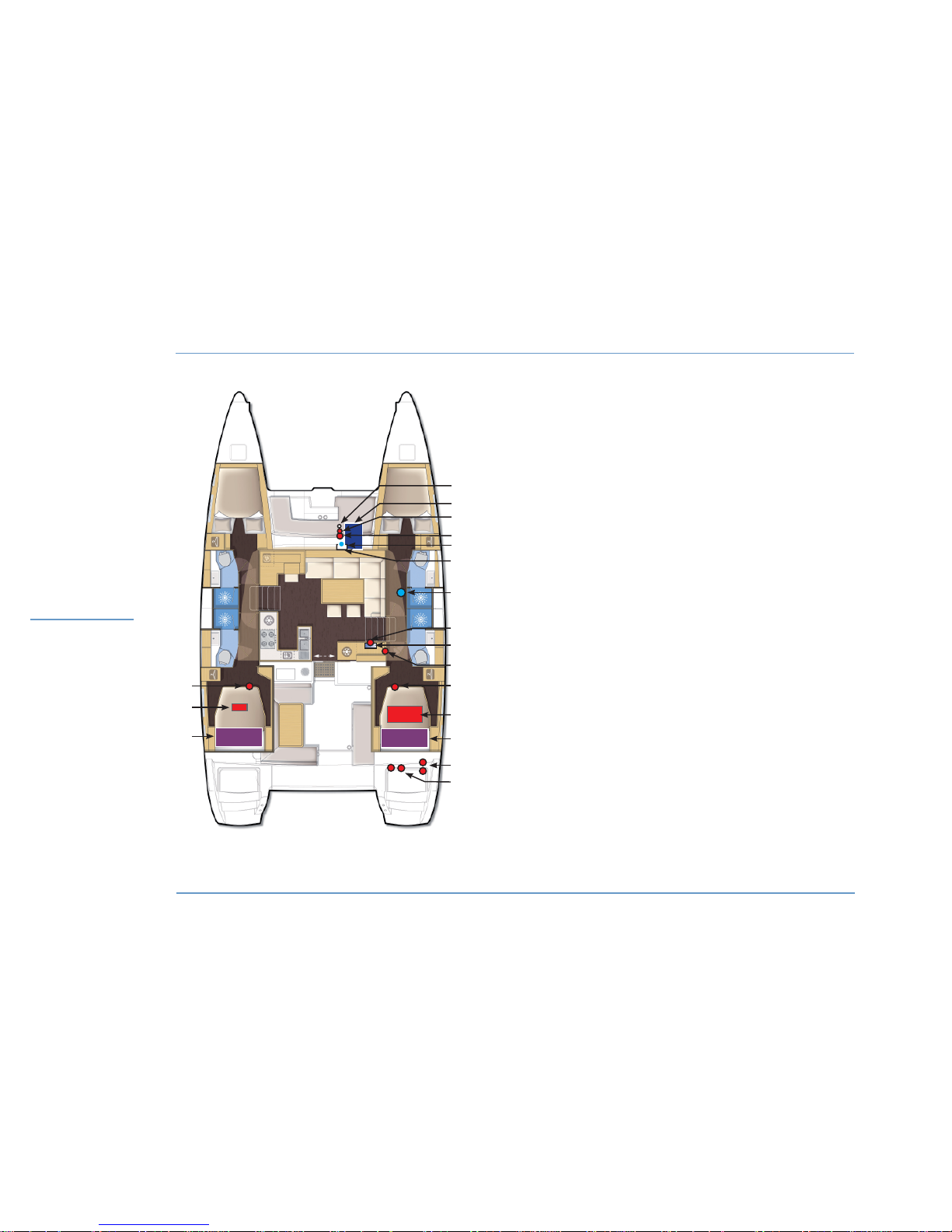
LAGOON 450
78
ELECTRICITY
ELECTRIC LAYOUT
1 - Fuel tank selection pull rod port / starboard.
2 - Generator.
3 - 12 V generator cutouts.
4 - Generator fuel filter.
5 - Generator water filter.
6 - 12 V battery chargers / Generator.
7 - Generator water inlet valve.
8 - Generator control.
9 - Electrical panel.
10 - Inverter.
11 - Cut outs board / engine + coupling.
12 - 12 V Batteries
port / starboard.
13 - Fuel tanks
port / starboard.
14A - 110 V - 220 V shore power socket / Air conditioning.
14B - 110 V - 220 V shore power socket / Board.
15A - Automatic breakers of the shore power sockets / Board.
15B - Automatic breakers of the shore power sockets / Air conditioning.
Nota: the same layout can be observed
in the other version.
2
3
1
6
8
7
9
10
11
12
13
14
15
5
4
12
11
13
Page 81

LAGOON 450
79
ELECTRICITY
SUMMARY FOR THE 12 V COMPONENTS
CHARGE AND ELECTRICAL CONVERSION
1 x 220 V / 12 V - 60 A charger 12 V service bank + engine
1 x 220 V / 12 V - 40 A charger (optional extra) Engines + board
1 x 220 V / 12 V - 25 A charger (optional extra) Generators
2 x 12 V - 80 A alternator Recharge service bank, batterie engines, generator
BATTERIES / CONSUMING APPLIANCES
12 V CURRENT VOLTAGE START + PROTECTION PROTECTION
Service batteries 12 V - 440 Ah (maximum)
Navigation electronics 12 V 12 V electrical panel
Lighting 12 V 12 V electrical panel
Navigation lights 12 V 12 V electrical panel
Refrigerators, conservator 12 V 12 V electrical panel
Electric toilets 12 V 12 V electrical panel
Deckwash pump 12 V 12 V electrical panel
Bilge pumps 12 V 12 V electrical panel
Winches 12 V 12 V board Electrical room
Windlass 12 V 12 V board Starboard aft cabin
VHF 12 V 12 V board 12 V terminal bloc
Hifi 12 V 12 V board 12 V terminal bloc
Car radio 12 V 12 V board 12 V terminal bloc
12 V sockets 12 V 12 V board 12 V terminal bloc
Engine battery (x2) 12 V - 110 Ah
Generator battery 12 V - 110 Ah
Domestic battery 12 V - 140 Ah
Page 82

LAGOON 450
80
SUMMARY FOR THE 110 V - 220 V COMPONENTS
ELECTRICITY
GENERATOR
Force 4 Kva - 11 Kva 100% of its charge in 220 V - 50 Hz
Force 5 Kva - 13,5 Kva in 110 V 100% of its charge in 110 V - 60 Hz
SHORE POWER SOCKET
Shore power socket Board 220 V - 50 Hz 32 A simple shore power socket Starboard transom connection
Shore power socket Air conditioning 220 V - 50 Hz 32 A simple shore power socket Starboard transom connection
Shore power socket Board 110 V - 60 Hz (version US) 32 A simple shore power socket Starboard transom connection
Shore power socket Air conditioning 110 V - 60 Hz (version US) 32 A simple shore power socket Starboard transom connection
ELECTRIC DISTRIBUTION
Selector #1 (on the right) Air conditioning supplied by generator or shore power
Selector #2 (on the left) Board supplied by generator or shore power (or 12 V / 220 V - 2000 W inverter)
CHARGE
1 x 220 V / 12 V - 60 A charger Recharge of the service bank by generator or shore power
1 x 220 V / 12 V - 40 A charger optional extra Engine battery charger supplied by the generator or the shore
1 x 220 V / 12 V - 25 A charger optional extra Generator battery charger supplied by the generator or the shore
Page 83

LAGOON 450
81
SUMMARY FOR THE 110 V - 220 V COMPONENTS
ELECTRICITY
CONSUMING APPLIANCES VOLTAGE BOAT ELECTRICAL PANEL
Television 220 V its own inverter
Outlets 220 V Inverter or 220 V panel
Water heater 220 V Panel 220 V
Dishwasher 220 V or 110 V Panel 220 V
Washer dryer 220 V or 110 V Panel 220 V
Icemaker 220 V or 110 V Panel 220 V
Watermaker 220 V or 110 V Panel 220 V
Air conditioning 220 V Panel 220 V
Page 84

Page 85

83
8.1 Engines
8.2 Fuel
8.3 Propellers - Anodes
8.4 Dash board
8.5 Optional controls
MOTORIZATION 8
Page 86
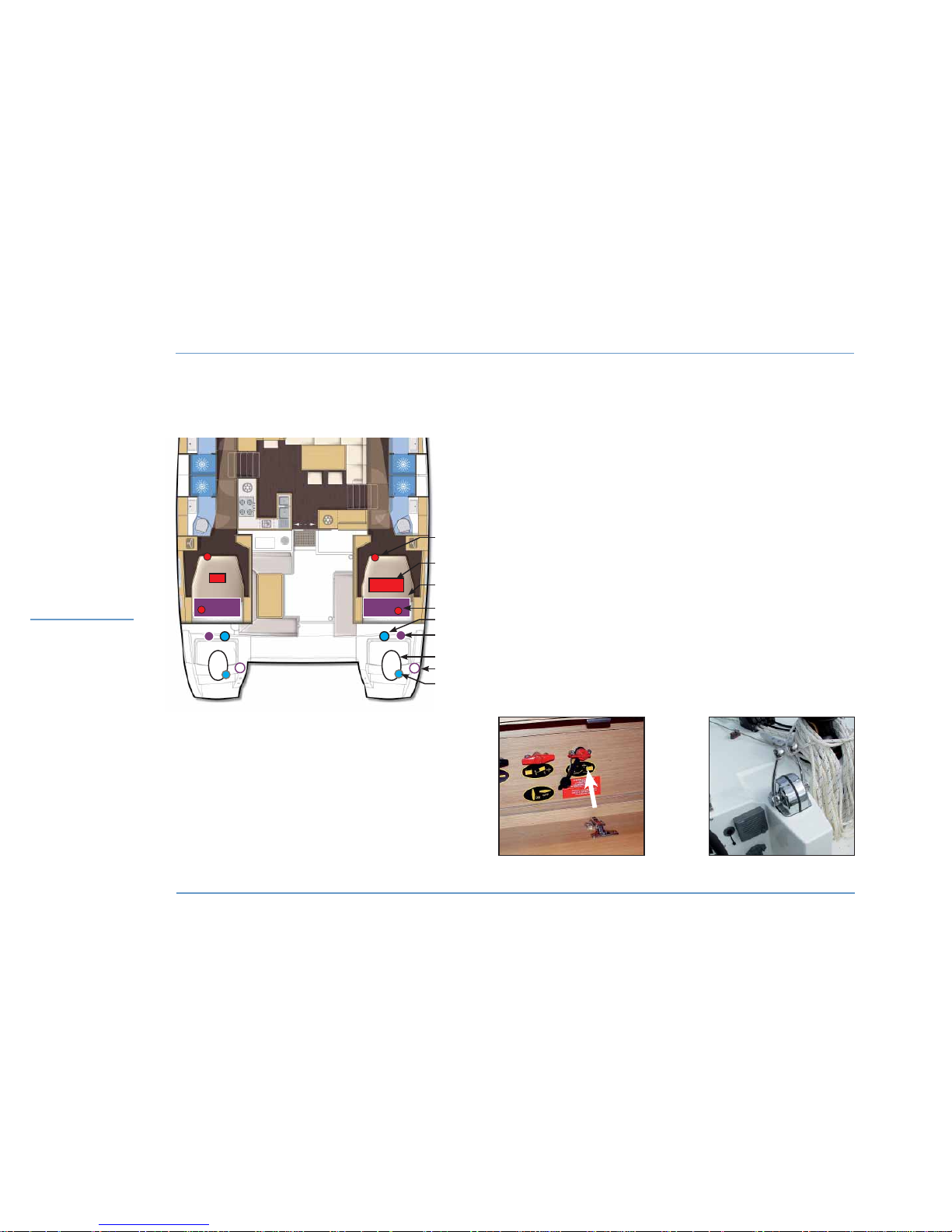
LAGOON 450
84
ENGINE LAYOUT
MOTORIZATION
1 - Engine cut outs + coupling (port).
2 - 12 V battery.
3 - Fuel tank.
4 - Fuel valve.
5 - Sea water filter.
6 - Fuel filter.
7 - Engine.
8 - Diesel oil tank fillers.
9 - Engine water inlet valve.
Each hull has the same components.
Nota: each valve in the boat is identified.
ENGINES CONTROLS
COUPLING CUT OUTS
Nota: the same layout can be observed
in the other version.
2
6
7
5
4
3
1
8
9
Page 87

Motonautisme
Motonautisme ou voile
z
Motonautisme ou voile
Motonautisme
Motonautisme ou voile
z
Motonautisme ou voile
LAGOON 450
85
8
MOTORIZATION
MOTORIZATION
8.1 Engines
z
ACCESS
You have access to the engines through the transom extension
hatches.
z
STARTING
Before starting the engines:
- Check the fuel valves are open (access under the aft cabins berths,
on the port and starboard tanks).
- Open the valves of the engine cooling system.
- Switch on the electrical circuit, setting the engines cutouts to ‘ON’
(access at the bottom of the starboard and port side berths).
- After having checked that the reverser handles are set on neutral,
start the engines.
Please carefully read the engine instruction guide supplied with the
boat; it gives you detailed explanations as to the best use of the engines and relative operations.
z
ENGINE START WITH BATTERY COUPLING
In case one of the start battteries is not available:
- Activate (ON position) the coupling cut out located at the bottom of
the port side berth.
- Start the engine concerned.
- Turn the coupling cutout back to
the OFF position.
Nota: in the standard configuration,the engine batteries are recharged
by their respective engines.
z
ENGINES MAINTENANCE
Please follow the instructions for maintenance appearing in the guide
supplied with the engines.
z
ENGINE WATER INLETS
The water inlet valves of the engines (access through the engines
holds) shall absolutely be open before you start the engines.
Keep the strainers of the engine water inlet valves in the best possible
state of cleanliness.
Brush the strainers when the boat is careened.
Be careful: do not cover the strainers with antifouling paint.
Get used to checking immediately after starting the engines if water is
expelled with the exhaust gases.
If water does not flow out:
- Stop the engines immediately.
- Check the valves are open.
Close the water inlet valves if the boat is left unattended for long.
Inspect and clean the water strainers regularly (access through the
engine holds).
ATTENTION
Stop the engines before opening the hatches.
In case you have to intervene when the engines are
running:
- Stay away from belts and mobile parts.
- Be careful with full clothes, long hair, rings, etc.
(they may be caught).
- Wear appropriate clothes (gloves, caps, etc.).
Page 88
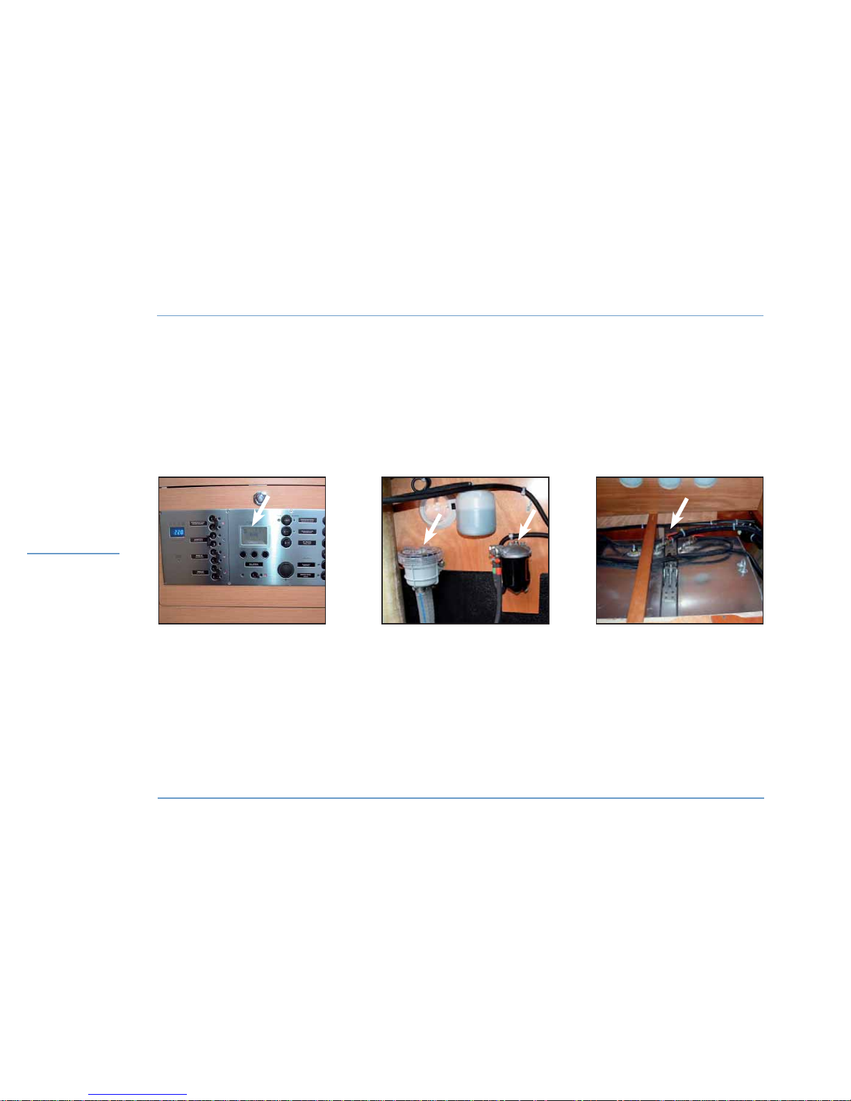
LAGOON 450
86
FUEL
MOTORIZATION
FUEL GAUGE
WATER FILTER + FUEL FILTER TANK + FUELLING VALVE
Page 89

Motonautisme
Motonautisme ou voile
z
Motonautisme ou voile
Motonautisme
Motonautisme ou voile
z
Motonautisme ou voile
LAGOON 450
87
8
MOTORIZATION
MOTORIZATION
z
MAINTENANCE OF THE TANKS
Regularly check the O rings of the fillers for good condition (to prevent
water from entering the tanks).
Do not turn off the fuel taps after each use (except in case the boat is
unattended for long).
Keep the fuel tanks as full as possible (to avoid condensation).
Every year check the fuel system for condition (hose, valves, etc.).
Ask a professional to carry out the works on the damaged parts of the
fuel system.
Please note: the capacity of the tanks (that is indicated in the page
‘SPECIFICATIONS’) may be not completely useable according to the
trim and load of the boat.
Always keep 20% fuel as a reserve.
z
FUEL FILTERS
In order to prevent any water infiltration, the fuel runs through two
filters: the first one is on the pipe that links the tank to the engine
(designed as a water decanter and pre-filter), the second one is an
integral part of the engine (designed to filter fuel finely). To know when
you have to intervene and how frequently you have to change them,
please refer to the engine instruction guide.
Drain it by undoing the knurled screw on the base of the decantation
bowl (but do not remove it).
Allow to flow into a box till the fuel looks clean.
Do it several times a year.
Change the pre-filter at least once a year (access to it when you remove
the bowl).
z
VENTILATION OF THE ENGINE BAY
The engine bay fans start up automatically as soon as the engines
start.
8.2 Fuel
z
FUEL TANKS
The boat is fitted with two tanks.
Each of them is filled separately.
Check the fuel gauge of each tank on the electrical board.
To switch from one tank to the other, press the "Fuel" button.
z
FILLING
To prevent any handling mistake, never fill the water and fuel tanks at
the same time.
During filling, avoid handling contaminants near the fillers.
Open and close the filler caps with the right key.
Use both fillers to fill the tanks with fuel.
DANGER
Stop the engine and put out your cigarettes when
you are filling the fuel tanks.
Page 90
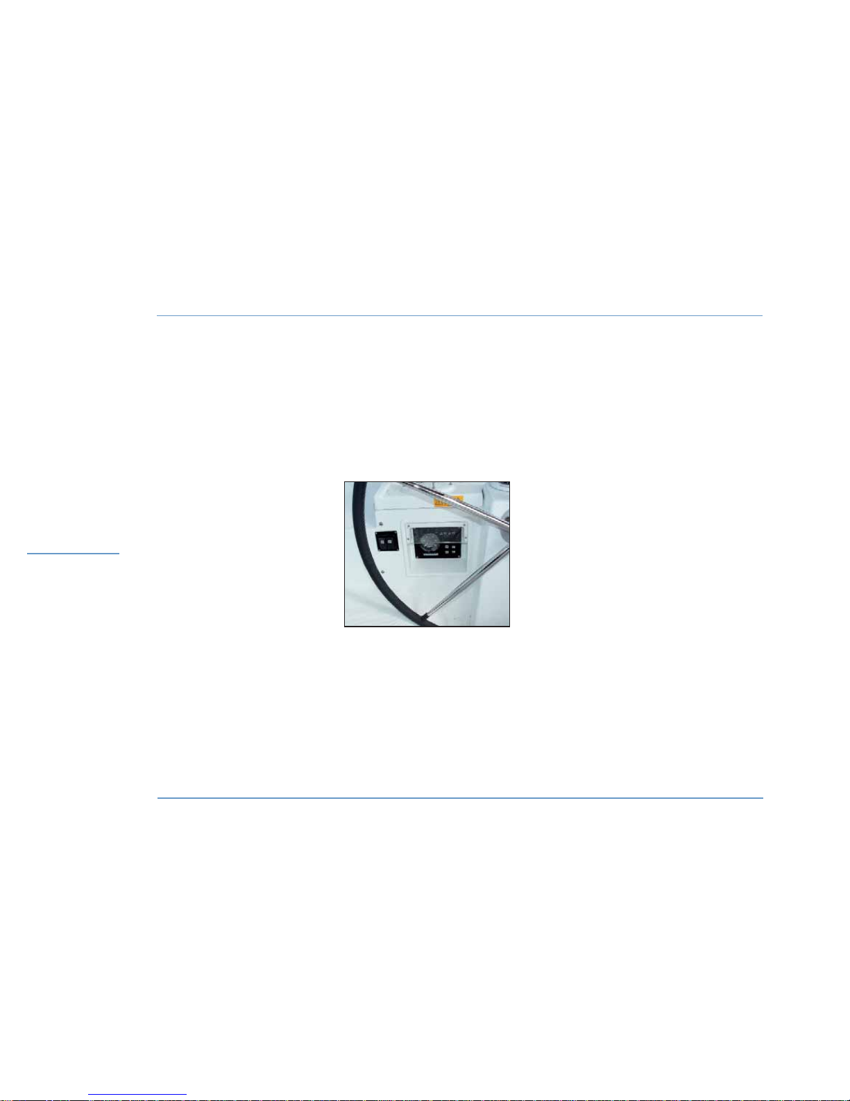
LAGOON 450
88
MOTORIZATION
DASH BOARD
DASH BOARD
Page 91

Motonautisme
Motonautisme ou voile
z
Motonautisme ou voile
Motonautisme
Motonautisme ou voile
z
Motonautisme ou voile
LAGOON 450
89
8
MOTORIZATION
MOTORIZATION
8.4 Dash board
On the dash board you can find all the functions to monitor the engine.
Please refer to the engine instruction guide supplied with the boat; it
gives you explanations about the indicator lights, dials and warning
lights on the dash board.
8.5 Optional controls
The boat may optionally be fitted with an extra engine control and with
joystick in the saloon.
Please refer to the appropriate user's manual regarding the engines
(with double control) and how to use them (joystick).
8.3 Propellers - Anodes
z
PROPELLERS
The propellers supplied with your boat are the result of tests carried
out jointly with the engine manufacturer.
Do not change them without consulting a specialist.
z
FOLDING PROPELLERS (OPTIONAL EXTRA)
Remove the folding propellers at the end of each season, dismantle
them and clean them carefully.
Grease the thrust bearing surfaces and teeth.
Check that the blades move easily.
z
ANODES
Regularly check the sacrificial anodes corrosion.
The wear of the anodes depends on numerous factors and their lives
may highly vary. Change them whenever necessary.
Never paint an anode.
Ask a professional to check and maintain the whole propulsion system.
Page 92

Page 93

91
9.1 Laying up
9.2 Protection
WINTER
STORAGE
9
Page 94
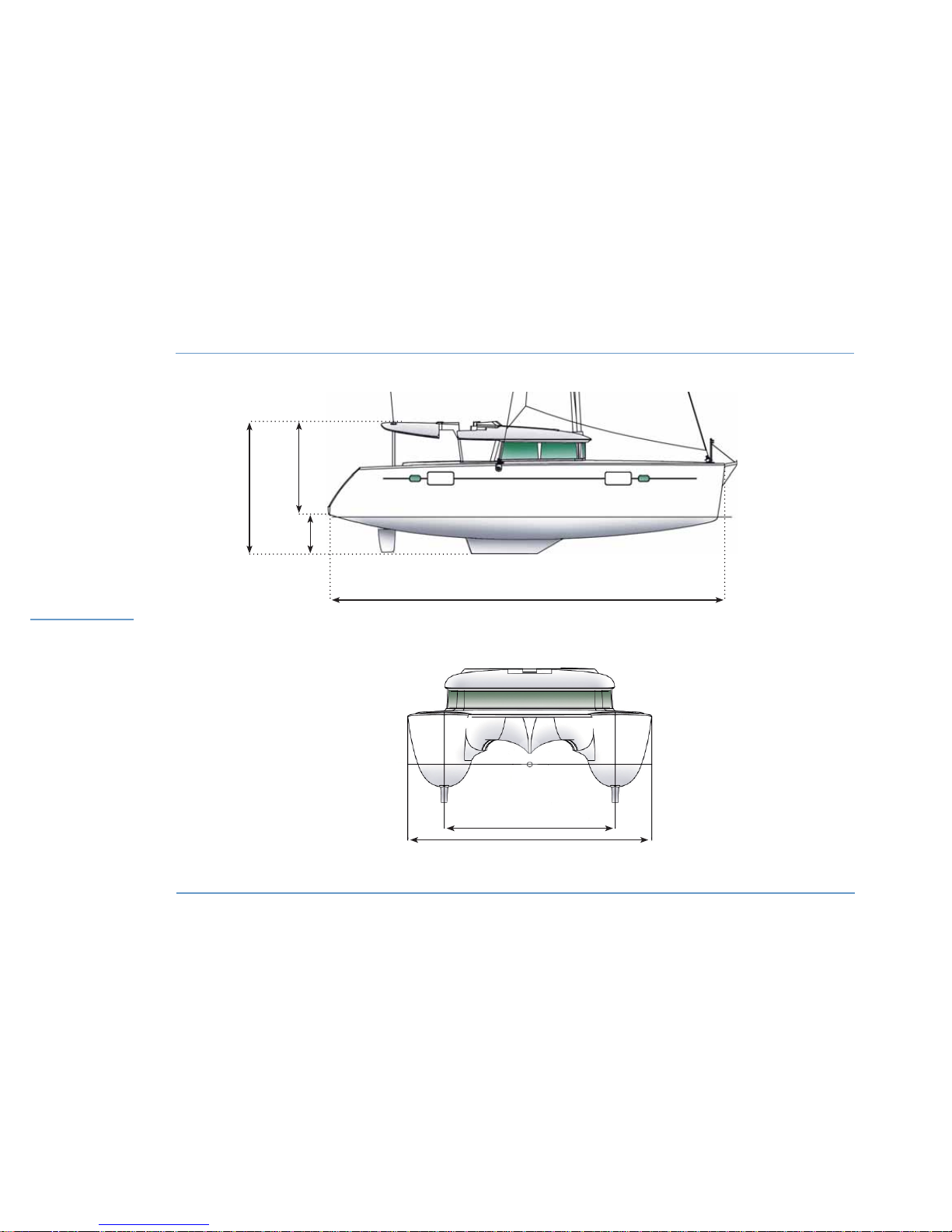
LAGOON 450
92
PACKING
WINTER STORAGE
13958 mm
4628 mm
2982 mm
1646 mm
5370 mm
7875 mm
Page 95

Motonautisme
Motonautisme ou voile
z
Motonautisme ou voile
Motonautisme
Motonautisme ou voile
z
Motonautisme ou voile
LAGOON 450
93
9
WINTER STORAGE
WINTER STORAGE
9.1 Laying up
- Take ashore all the ship’s log, the ropes that are not used for mooring
her, the galley equipment, supplies, clothes, the safety equipment.
- Check the expiry dates of the safety equipment.
- Have the liferaft overhauled.
Take advantage of this laying up to draw up a complete inventory of
the equipment.
9.2 Protection
z
WATER SYSTEM
- Drain the fresh water system.
Let water run from the taps until the system runs dry.
Check that there is no water left in the pipes and hoses (possible low
points).
- Take off the filters, remove the water.
Clean the filters if necessary then put them back.
- Drain the water heater.
Check that there is no water left.
Close the drain.
- Lubricate all the water inlet valves and sea cock fittings.
- Rinse and completely drain the toilets bowls.
z
INSIDE
- Seal air inlets as much as you can.
- Install an air dehumidifier in the saloon and leave the cabin and
storage unit doors open (stowage cupboards, icebox).
- Leave the cushions outside for long before putting them back into
the boat in the upright and side position in order to have minimum
contact surfaces.
- Drain and clean the bilges.
- Possibly place the floorboards in a vertical position to make possible
the ventilation of the different compartments.
- Open the refrigerators / conservator doors.
z
OUTSIDE
- Carefully drain the cockpit shower.
- Thoroughly rinse the hull and deck.
- Lubricate all the mechanical and mobile parts with vaseline (bolts,
hinges, locks, etc.).
- Protect all ropes and mooring lines against chafing.
- Protect the boat to the highest degree with fenders.
- Make sure the boat is properly moored.
z
ENGINES
The engines winterizing has to be prepared by a specialist.
The preparation for winterizing is different according to the place
where the boat will be stored - either in the water or on the shore.
RECOMMENDATION
All these recommendations do not make up an
exhaustive list. Your dealer will give you the advice
you need and will carry out the technical maintenance
of your boat.
Page 96

Page 97

95
10.1 Preparation
10.2 Crane lifting
10.3 Mast stepping and removal
HANDLING 10
Page 98
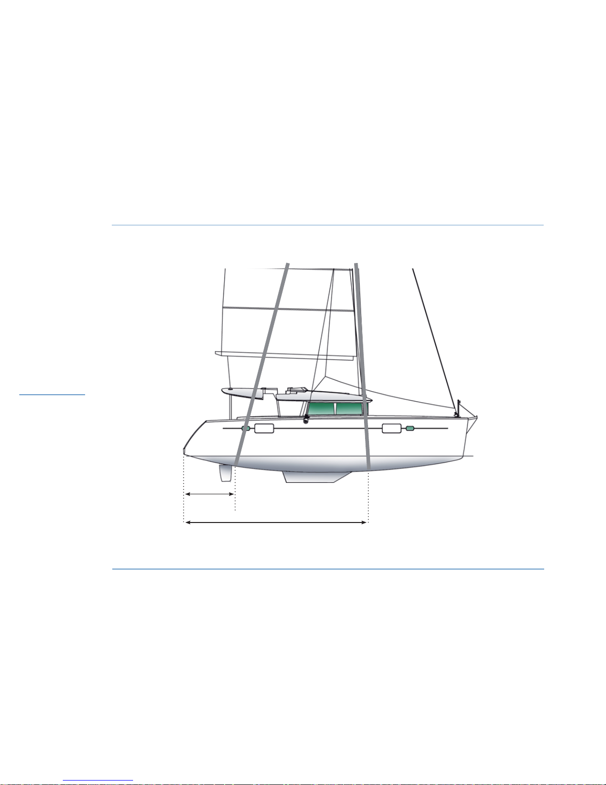
96
HANDLING
CRANE LIFTING INSTRUCTIONS
6470 mm
2398 mm
LAGOON 450
Page 99

97
10
HANDLING
HANDLING
10.1 Preparation
The initial launching and the first tests of the different equipments
shall be carried out by your dealer so that you can expect to enjoy the
warranty in case of some equipment failure.
All further handling shall be carried out with the highest care by professionals.
If the LAGOON boatyard are not involved in your handling operations,
they cannot cover under guarantee any possible accidents linked to
handling.
If later you have to launch your boat yourself, you should take the
following precautions:
- Retract the sensors under the hull into their housings (they may be
damaged by the handling slings).
- Check the water suction boxes for cleanliness.
- Turn off all the water inlet and drain valves (grey waters, black waters, engine).
- Check the anodes are in good condition and properly installed. An
anode shall never be painted.
10.2 Crane lifting
- Install a bow mooring rope, a stern mooring rope and fenders.
When using a crane to move the boat, check that slings cannot touch
any device (depth finder, speedometer, etc.) nor the propellers.
The crane hook will be fitted with a gantry or a spreader system with
two slings.
The slings shall not be connected directly onto the hook, as it would
result in unusual compressive stresses on the hull.
- Crane lifting should be carried out slowly.
- Control the movement of the boat using mooring ropes.
10.3 Mast stepping and removal
Mast stepping and removal shall be carried out by a professional.
DANGER
Do not stay on board or under the boat during
craning.
LAGOON 450
Page 100

 Loading...