

Page 1
User’s gguide
Page 2

Page 3

We share a common passion for the sea: we, LAGOON, as boat-builders and
you, who want to live out your enthusiasm for the ocean.
We are delighted to welcome you to the great family of LAGOON boat owners
and we would like to congratulate you on your purchase.
This instruction guide is intended to help you to enjoy your boat in comfort and
safety. It includes the boat specifications, the equipment provided or installed,
the systems on board and tips on use and maintenance. Read this manual
carefully before you put out to sea so that you can make the most of her and
avoid any damage and difficulties. Read it carefully and familiarize yourself
thoroughly with your boat before sailing.
In order to share as much new technology, new equipment and new materials
with you as possible, our boats are constantly improved. This is why the
specifications and information given are not contractual and can be modified
without notice and we are not obliged to provide updates.
This instruction guide has a general purpose and it may mention some
equipment or accessories or deal with some points or questions that are not
relevant to your own boat ; if in doubt, refer to the inventory that you received
on delivery of your boat.
If this is your first boat or if you are changing to a new type with which you
are not familiar, first obtain some training in boat handling and sailing to
ensure your safety and comfort before taking the helm of your boat. Your
dealer, international sailing association or yacht club will be able to
recommend local sailing schools or professional instructors.
Although everything possible has been planned and designed with the safety
of the boat and its users in mind, remember that sailing is highly dependent
on the weather conditions and the conditions of the sea, and that only an
experienced and very fit crew, handling a well-maintained boat, can sail
satisfactorily.
The sea and wind conditions that correspond to design categories A, B and C
are changeable and are still susceptible to the risk of unusually large waves
or strong gusts of wind. Total safety cannot therefore be guaranteed, even if
your boat meets the requirements of a category.
Always consult the weather and shipping forecasts before
taking your boat out to sea.
Make sure that the sea and wind conditions forecast
correspond to the category of your boat, and that you and
your crew are able to handle the boat in these conditions.
Our network of LAGOON authorized dealers is available to
help you get acquainted with your boat and is best qualified
to take care of her maintenance.
Page 4

The sea and the water are not Man's natural environment and we must
respect their laws and their strength.
Adapt the use of your boat to her condition, which deteriorates with time and
use.
Any boat, however well built, may be severely damaged if badly used. This is
not compatible with safe sailing. Always adapt the speed and direction of your
boat to the sea conditions.
The 'COLREG' international regulations for the prevention of collisions at sea,
published by the International Maritime Organization, specify the rules relative
to steering and courses, navigation lights etc. throughout the world. Make sure
that you are familiar with these regulations and that you have a list present on
board which explains them.
In many countries, a license, an authorization or training certificate will be
required.
Make sure you have the necessary legal authorization before you use your
boat.
Always ensure an experienced professional carries out the maintenance of
your boat, installs any accessories and makes any small modifications. The
written authorization of the builder or his legal representative is compulsory
for modifications that alter the specifications of the boat, in particular the
vertical arrangement of forms (installing radar, modifying the mast, changing
the engine etc.).
Users of the boat are informed of the following:
- The entire crew must be properly trained.
- The boat must not carry a load heavier than the maximum load
recommended by the builder, in particular the combined weight of food
supplies, equipment not supplied by the builder and people on board. The
weight carried by the boat must be properly distributed.
- The water in the bilge must be maintained at a minimum.
- Stability is reduced when you add weight to the upper sections.
- In the event of heavy weather, the hatches,lockers and doors must be closed
in order to minimize the risk of water entering the boat.
- Stability may be reduced when towing another boat or when lifting heavy
weights using the davits or the boom.
- Breaking waves are a serious danger to stability.
- If your boat is equipped with a life-raft, read the instructions carefully.All the
proper safety equipment must be carried on board (harnesses, flares, life-raft,
etc.) according to the type of boat, the country in which it is used, the weather
conditions, etc.
- The crew must be familiar with the use of all the safety equipment and all
emergency safety procedures (MOB, towing etc.).
- All people on deck must wear a life jacket or a buoyancy aid. Please note that
in some countries it is compulsory to wear an approved buoyancy aid at all
times.
Keep this manual in a safe place and give it to the new
owner if you sell your boat.
For standard or optional equipment (engine, electronics etc.)
refer to their respective manuals supplied with your boat.
Page 5

CONTENTS
Using your boat
1 Navigation .......................................................................................5
2 Winter storage...............................................................................23
3 Launching .....................................................................................27
Construction and equipment
4 Hull & deck....................................................................................35
5 Layouts .........................................................................................43
6 Electricity.......................................................................................53
7 Plumbing .......................................................................................69
8 Motorization ..................................................................................79
9 Rigging and Sails ..........................................................................89
10 Safety ............................................................................................99
11 General specifications ................................................................111
Notes
3
UPDATED: 02/2010
Chapter Page number
Page 6

Page 7

5
GETTING UNDER WAY . . . . . . . . . . . . . . . . .
7
NAVIGATION VISIBILITY
. . . . . . . . . . . . . . . 7
NAVIGATION UNDER MOTOR . . . . . . .
9
NAVIGATION UNDER SAIL
. . . . . . . . . . . 11
DOCKSIDE . . . . . . . . . . . . . . . . . . . . . . . . . . . . . . . . 17
TOWING . . . . . . . . . . . . . . . . . . . . . . . . . . . . . . . . . . . 17
ANCHORING . . . . . . . . . . . . . . . . . . . . . . . . . . . . . 17
DAVITS. . . . . . . . . . . . . . . . . . . . . . . . . . . . . . . . . . . . . 21
ENVIRONMENT . . . . . . . . . . . . . . . . . . . . . . . . . 21
Navigation
1
Page 8
GETTING UNDER WAY
6
NAVIGATION
LAGOON 44O
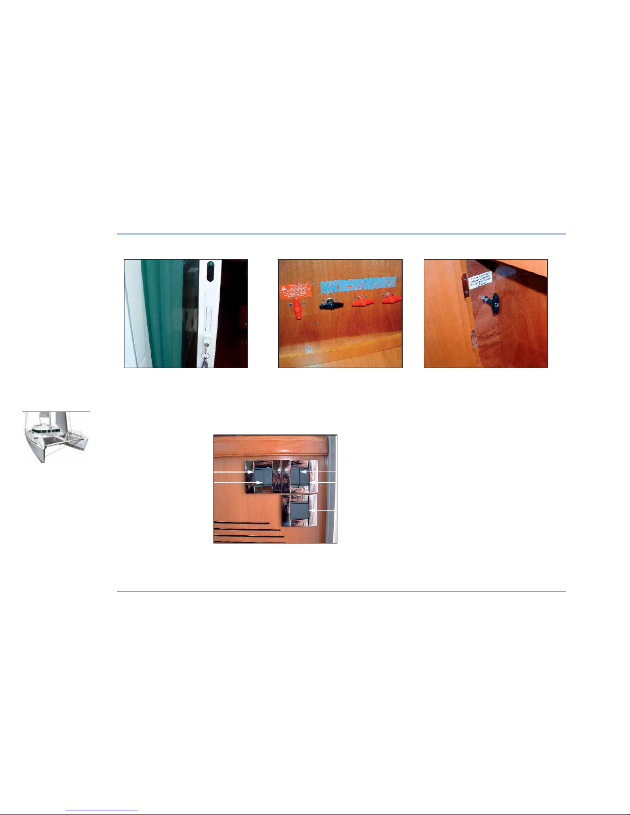
BLOCKING OF
SLIDING DOOR
PORT AND STARBOARD
AFT CABIN
BATTERY SWITCHES
ENTRY SWITCHES
1
1 - Saloon ceiling light switch, starboard.
2 - Saloon ceiling light switch, entrance.
3 - Saloon ceiling light switch, central.
4 - Cockpit spotlight switch.
5 - Courtesy lighting switch (optional extra).
2
3
4
5
FUEL VALVE
Page 9
Getting under way
The sliding door locks in three different positions: closed, ajar (airing
position) and open.
A latch on the doorframe enables locking from inside the saloon.
Switch on the main power of the boat by activating the battery
switches located in the port and starboard aft cabins, then activate
the different accessory switches on the electrical panel.
Check the charge rate of the batteries, the water level in the tanks and
the fuel level (see ELECTRICITY and MOTORIZATION chapter).
Carry out the inventory of compulsory safety equipment and instruct
the crew concerning its location and operation.
Visibility in navigation
The international regulations to prevent collision at sea (COLREG) and
course regulations make mandatory a permanent and proper
surveillance and the respect of priority.
Make sure there is no other boat in your way.
Visibility from the steering station may be obstructed by the following:
- Load and load distribution.
- Sea conditions, rain, spray, fog or darkness.
- Lights on inside the boat.
- People and mobile equipment in the helmsman's field of visibility.
NAVIGATION
7
NAVIGATION
1
LAGOON 44O
RECOMMENDATION
While sailing block the sliding door shut.
RECOMMENDATION
When entering the saloon be careful of the step
leading down into the port hull.
DANGER
Remember to disconnect the shore power supply
before casting off.
Page 10
8
NAVIGATION
LAGOON 44O
Page 11
Navigation under motor
Before starting the engine:
- Ensure that the fuel valves are open.
- Open the valves for the engine cooling systems (see chapter
MOTORIZATION).
To start the engines, refer to the manufacturer's manual too.
z
ENGINE STARTING
Turn on the battery switches located in the port and starboard aft
cabins.
- Disengage the gear (to allow acceleration in neutral).
Proceed in the following order:
- Start the port engine first.
- Then start the starboard engine.
After starting the engine check for cooling water running out of the
exhaust and observe the color of exhaust gases.
z
BATTERY COUPLING
In the case of low engine battery power use the battery coupling
function by turning on the coupling handle located in the starboard aft
cabin.
Once the engines have been restarted make sure that the coupling
handle is turned back to its original position.
z
NAVIGATION
When using the engine, avoid making noise and waves near other
users.
Respect speed limits.
NAVIGATION
9
NAVIGATION
1
LAGOON 44O
WARNING
Never cut off the ignition or the electrical circuit
when the engine is running.
Page 12
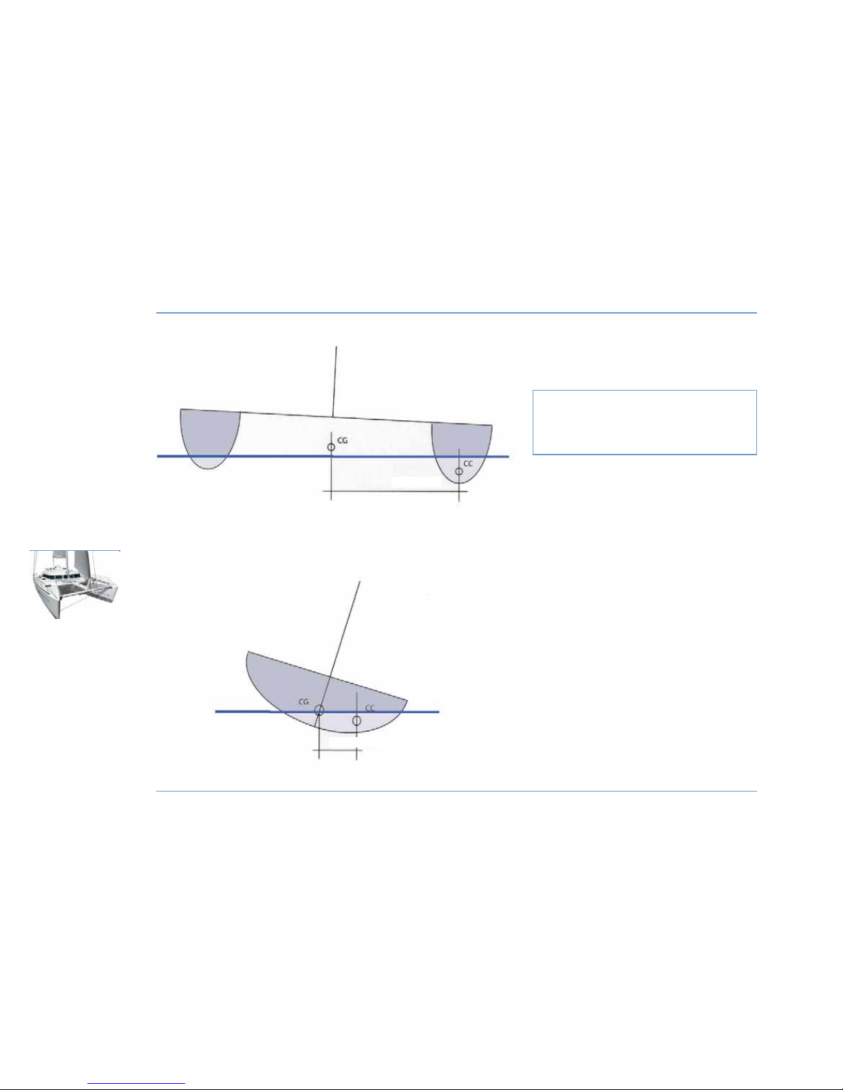
Illustration showing the difference between
the righting moments of a single-hull vessel
and a catamaran of 10m length.
d: distance between centre of buoyancy and centre of
gravity.
RMmax: weight of vessel x d
(RMmax: maximum righting moment)
RRMMmmaaxx ssiinnggllee-hhuullll
: 10 tons x 0.5 meters
:
55 ttoonnss..mmeetteerrss
RRMMmmaaxx ccaattaammaarraann
: 10 tons x 3 meters
:
3300 ttoonnss..mmeetteerrss
RIGHTING MOMENT
10
NAVIGATION
LAGOON 44O
CATAMARAN
Weight of vessel: 10 tons
SINGLE-HULL
Weight of vessel: 10 tons
d = 3 meters
d = 0.5 meter
Page 13
Navigation under sail
z
BEWARE
A catamaran presents 6 times greater heel resistance than a singlehull vessel. In terms of ship design we speak of righting moment
(multiplication of the vessel's weight by the transverse distance
between the centre of gravity and the centre of flotation (or
buoyancy).
See illustration on previous page.
This fact has real consequences for the handling and sail-trimming of
a catamaran.
The fact that the boat will not heel over could conceal an excessive
sail surface area in use, which could be dangerous for the crew and
the vessel. It is therefore essential to constantly monitor the real wind
speed and to trim the sail surface area as a priority in accordance
with this speed.
These latter adjustments are valid in calm seas. In rough seas one
should take the precaution of reducing 10% earlier in terms of real
wind speed. Generally speaking, it is essential to constantly look to
relieve the vessel rather than to put it under stress.
One should always look for the sail angle of attack to be headed to the
apparent wind and the sails to be not over-trimmed so that the
airflows leaving the sail are parallel to each other, that is to say they
do not create turbulence behind the sail.
Failure to follow the above recommendations can be dangerous for
the boat and the crew, and the manufacturer cannot be held
responsible in the event of an accident.
z
CLOSE HAULED TRIMMING (between 75 and 50° to true wind)
GGiivveenn wwiinndd ffoorrccee iinn aappppaarreenntt wwiinndd
- FFrroomm 00 ttoo 1166 kknnoottss
: full sail; mainsail traveler 30 cm to windward of
center, mainsail trimmed with a slightly opened leech (boom
centered).
The Genoa jib is trimmed near the spreader, the Genoa traveler is
placed so that the angle of the Genoa sheet forms a straight line with
the clew and the luff, at 40% of its height.
- FFrroomm 1166 ttoo 2200 kknnoottss
: full sail; the mainsail traveler moves up to 60
cm to windward of center,mainsail trimmed with a slightly more open
leech (boom still in line: so the sheet will have to be slackened).
The Genoa traveler does not change position but adjust the sheet so
that the leech is 10 cm from the spreader.
- FFrroomm 2200 ttoo 2266 kknnoottss
: 1 reef, full Genoa; the mainsail traveler comes
back to 30 cm to windward of center.
The Genoa traveler does not change position but the sheet is
slackened slightly so that the leech is 20 cm from the spreader.
- FFrroomm 2266 ttoo 3300 kknnoottss
: 1 reef, 75% of the Genoa; the mainsail traveler
moves up to 60 cm to windward of center.
The Genoa traveler remains in place or moves slightly forward but it
is adjusted so that the leech forms a propeller, the upper part
dumping air out under strong gusts of wind.
- FFrroomm 3300 ttoo 3366 kknnoottss
: 2 reefs, 60% of the Genoa; the mainsail
traveler returns to the 30 cm to windward of center, the boom is
slackened to fly 50 cm leeward.
The Genoa traveler is moved slightly forward, the adjustment remains
the same.
NAVIGATION
11
NAVIGATION
1
LAGOON 44O
Page 14
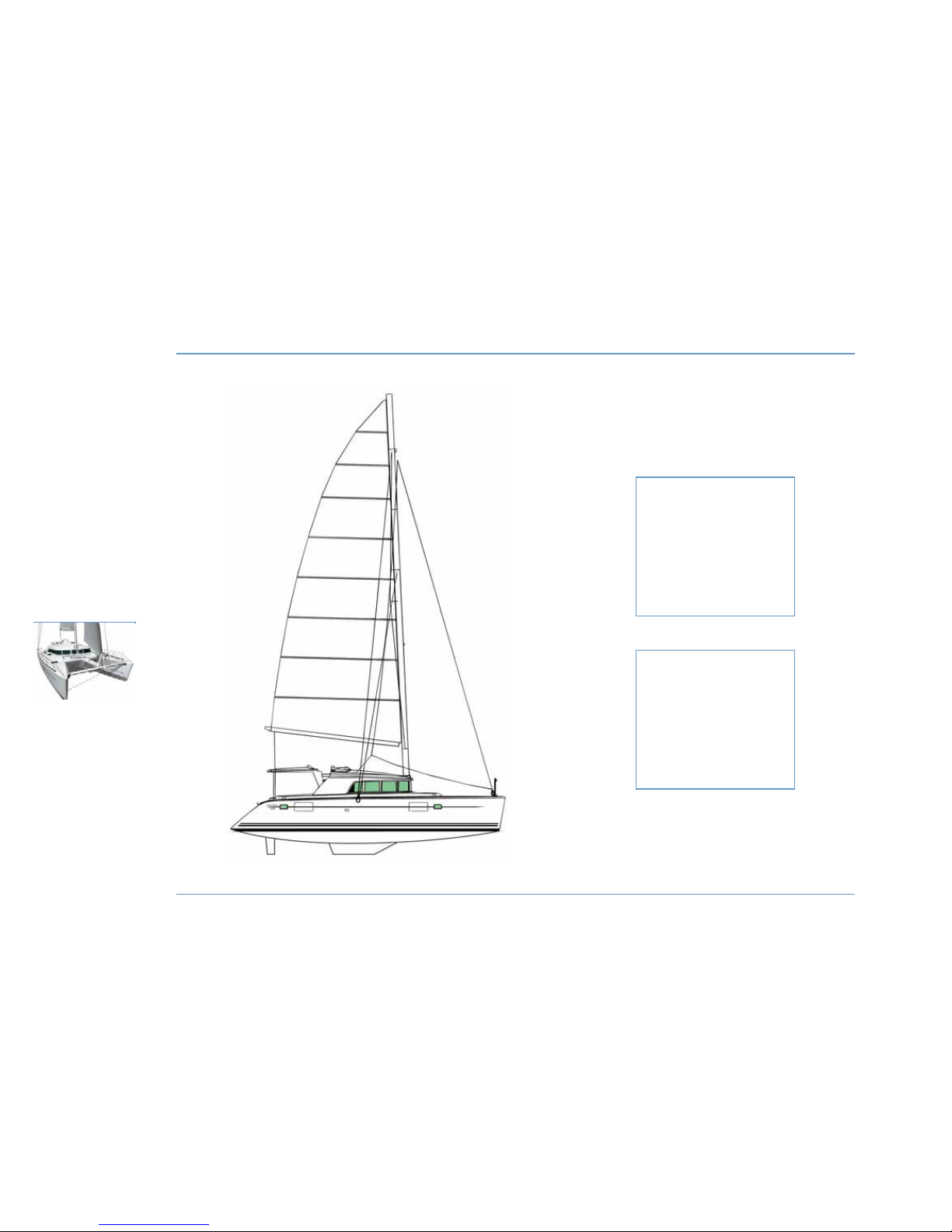
SAILS
12
NAVIGATION
LAGOON 44O
SURFACE AREA OF MAINSAIL
STANDARD EUROPE MAST
Mainsail high: 71.30 m2.
Mainsail 1 reef: 59.10 m2.
Mainsail 2 reefs: 44.20 m2.
Mainsail 3 reefs: 29.40 m2.
SURFACE AREA OF MAINSAIL
SHORT MAST
mainsail high: 58.70 m2.
mainsail 1 reef: 39.30 m2.
mainsail 2 reefs: 31.20 m2.
mainsail 3 reefs: 21.10 m2.
Page 15
- FFrroomm 3366 ttoo 4455 kknnoottss
: 2 reefs, 40% of the Genoa. The mainsail
traveler is dead center and the boom veers 1 meter to leeward.
The Genoa traveler moves forward slightly, the sheet is slackened to
open wide in strong wind conditions.
- FFrroomm 4455 ttoo 5555 kknnoottss
: 3 reefs alone (either storm sail or lie to),
traveler in the center, mainsail out by 1 meter.
The boat will be more at ease scudding in this weather.
- OOvveerr 5555 kknnoottss::
lie to, drag anchor or, preferably, scud bare poles.
z
CLOSED REACHED TRIMMING (between 75 and 130° to true wind)
- FFrroomm 00 ttoo 2233 kknnoottss
: full sail; the traveler is positioned between 1
meter from centre up to windward of center, depending on the wind
angle, the sheet is slackened so that boom is veering out anything
from 50 cm in calm weather to 2 meters when the wind is forcing.
In every case no more than one batten should be allowed to chafe at
the shroud at the fastest speeds.
The Genoa jib is slackened so that its average attack angle is head on
to the apparent wind.
- FFrroomm 2233 ttoo 2288 kknnoottss
: 1 reef, full Genoa. The adjustments are
identical.
- FFrroomm 2288 ttoo 3333 kknnoottss
: 2 reefs, 80% of the Genoa. The adjustments
remain identical.
- FFrroomm 3333 ttoo 3388 kknnoottss
: 2 reefs, 60% of the Genoa. The adjustments
remain identical.
- FFrroomm 3388 ttoo 4455 kknnoottss
: 3 reefs (or mainsail lowered and a little more
Genoa), 40% of the Genoa. The adjustments remain identical.
- FFrroomm 4455 ttoo 5555 kknnoottss
: mainsail lowered, 40 to 30% of the Genoa,
sufficiently trimmed so as not to flap.
- OOvveerr 5555 kknnoottss
: scudding, depending on the sea conditions the
mooring lines can be looped round behind the vessel and attached on
the opposite side to act as a brake.
These indications are given for your information only and are
dependant on outside conditions.
NAVIGATION
13
NAVIGATION
1
LAGOON 44O
WARNING
Your boat is designed to sail without the need to
climb onto the roof for any maneuvers. It is
dangerous to climb or stay on the roof particularly in
the event of gibing.
Keep children under close supervision.
RECOMMENDATION
Under sail put all engine controls in neutral to avoid any
damage to engines (with fixed or folding propellers).
Page 16
14
NAVIGATION
LAGOON 44O
Page 17
z
REDUCING SAIL
The boat is fitted with 3 reefs.
Reefs n°1 and n°2 are automatic, n°3 is traditional.
The luff eyelet of reef n°3 is fitted with a strap with a snap shackle to
clip on to the eye bolt on the boom.
Putting in reefs n°1 and n°2:
1 - Head the boat into the wind.
2 - Pull tight the topping lift.
3 - Slacken the mainsail sheet.
4 - Slacken the mainsail halyard and then trim reef line n°1 or n°2,
as needed, until the reefing blocks which correspond to the luff and
the mainsail leech are a few centimeters from the boom.
5 - Close the line cam cleat of the respective reef.
6 - Hoist taut the mainsail halyard.
7 - Slacken the topping lift and take in the mainsail sheet.
Follow the lowering and raising of the sail with the help of the head
downhaul.
Putting in reef n°3:
Repeat steps 1 to 3 as before, then:
4- Slacken the mainsail halyard then trim reef line n°3 until the
mainsail leech block is a few centimeters away from the boom.
- Clip the snap shackle on the luff eyelet of reef n°3 onto the eye bolt
located on the boom.
- Take up the slack in the lines of reefs n°1 and 2.
- Repeat steps 5 to 7 as before.
Refer to the running rigging diagram (chapter on RIGGING AND SAILS)
for identification of ropes.
z
NAVIGATION WIND ASTERN
- Do not fall off more than 150° to the apparent wind.
- Put the traveler out as far as possible and slacken the sheet slightly.
- Make sure the mainsail does not touch the shrouds; the rubbing of
the battens will wear the material and cable very rapidly.
- Keep mainsail + solent up to 15 knots speed and put in one reef or
more if the accelerations are sudden and strong or if sea conditions
deteriorate.
NAVIGATION
15
NAVIGATION
1
LAGOON 44O
RECOMMENDATION
For safety, the reef line used should always stay on
the winch with 3 turns around the drum.
Re-close the cam cleat for greater safety.
Page 18
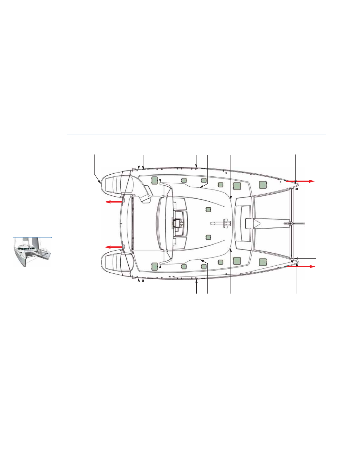
DECK LAYOUT
16
NAVIGATION
LAGOON 44O
1 - Midship cleat for towing.
2 - Midship cleat.
3 - Jack-line fastening.
4 - Swimming ladder.
5 - Anchor bridle fastening.
6 - Padeye/spinnaker/gennaker sheet block.
26
4
5
1
1
1
1
2
22 6 3 3 3
3 3 3 6
5
6
Page 19
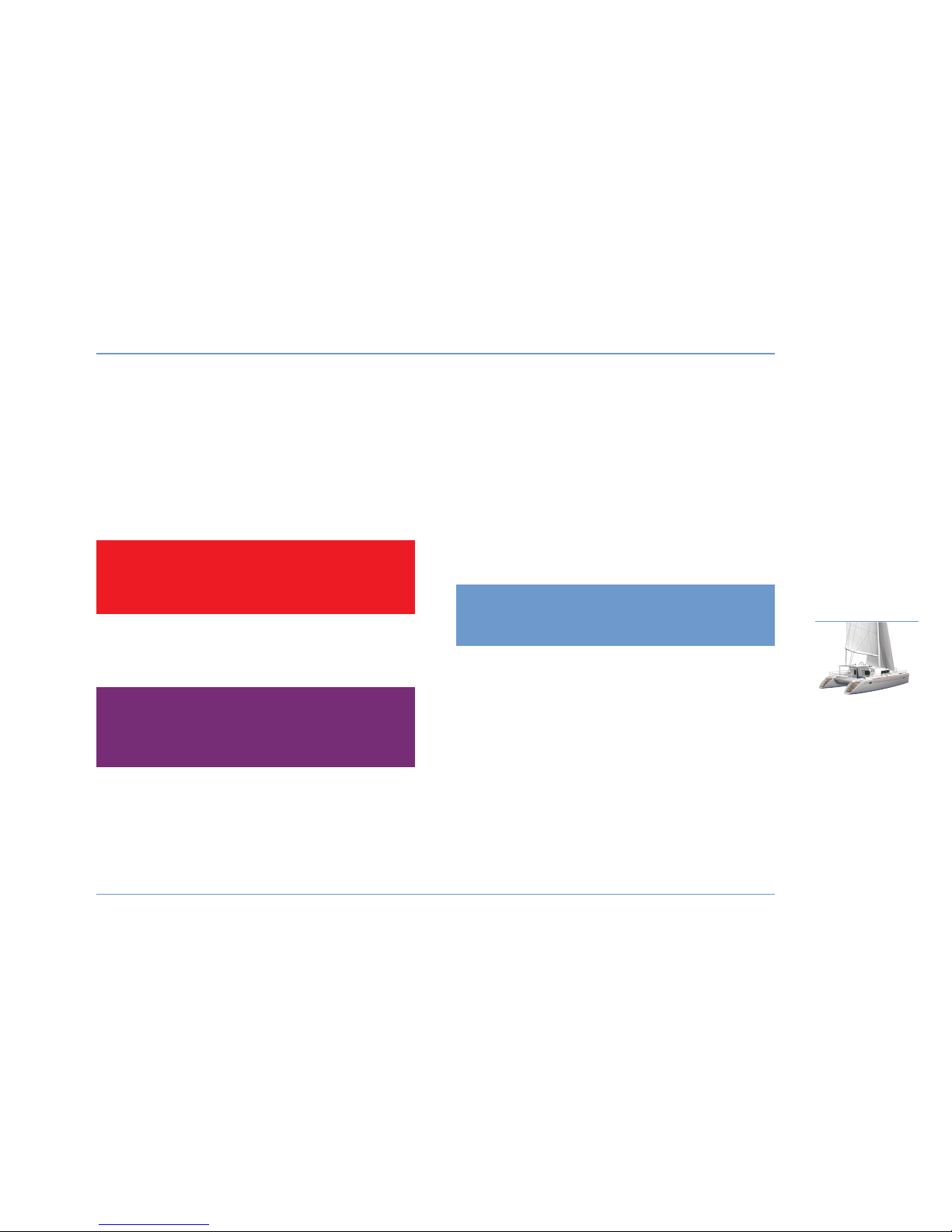
Mooring
A sufficient number of dockside lines of a size suitable for the
environment should be on board for mooring your boat.
- Always maneuver your boat using the engine.
- Make allowances for currents and wind when handling your boat.
- Protect your boat properly with suitably sized fenders.
- Always keep the dockside lines clear and stored away.
- Maneuver at a reduced speed.
AFTER MOORING
- Protect the dockside lines from chafing with chafe guards.
- Allow for tide variations if necessary.
Towing
TOWING
Tow another boat at a reduced speed and as smoothly as you can.
Be particularly careful when throwing or catching the towing line (it
may catch on the propeller).
N.B.: Stability may be reduced when towing a boat.
BEING TOWED
- Keep steering your boat and ensure you stay in the wake of the
towing boat.
Anchoring
As a rule, set the anchor line at least 3 times the water depth.
z
PREPARATION OF ANCHORING (illustrations following page)
- Install the bridle by fixing it to the chain plates located at the ends
of the fore beam.
- Put the bridle through the stem bow roller.
- Shackle the bridle to the central cleat during the lowering of the chain.
z
MANUAL ANCHORING
- Point your boat into the wind and at zero speed.
- Release the brake on the chain lifter.
- Pay out the chain while reversing slowly.
- Secure the anchor chain on the bridle.
- Lead out the chain until the guy becomes taut.
NAVIGATION
17
NAVIGATION
1
LAGOON 44O
DANGER
Do not try to stop the boat with your foot, your hand
or a boat hook.
RECOMMENDATION
Before anchoring check the depth of water, the
power of the current and the nature of the sea bed.
WARNING
Do not let the hull's large plexiglass windscreens come
into contact with fenders or hawsers: surface damage
would be irreparable.
Page 20
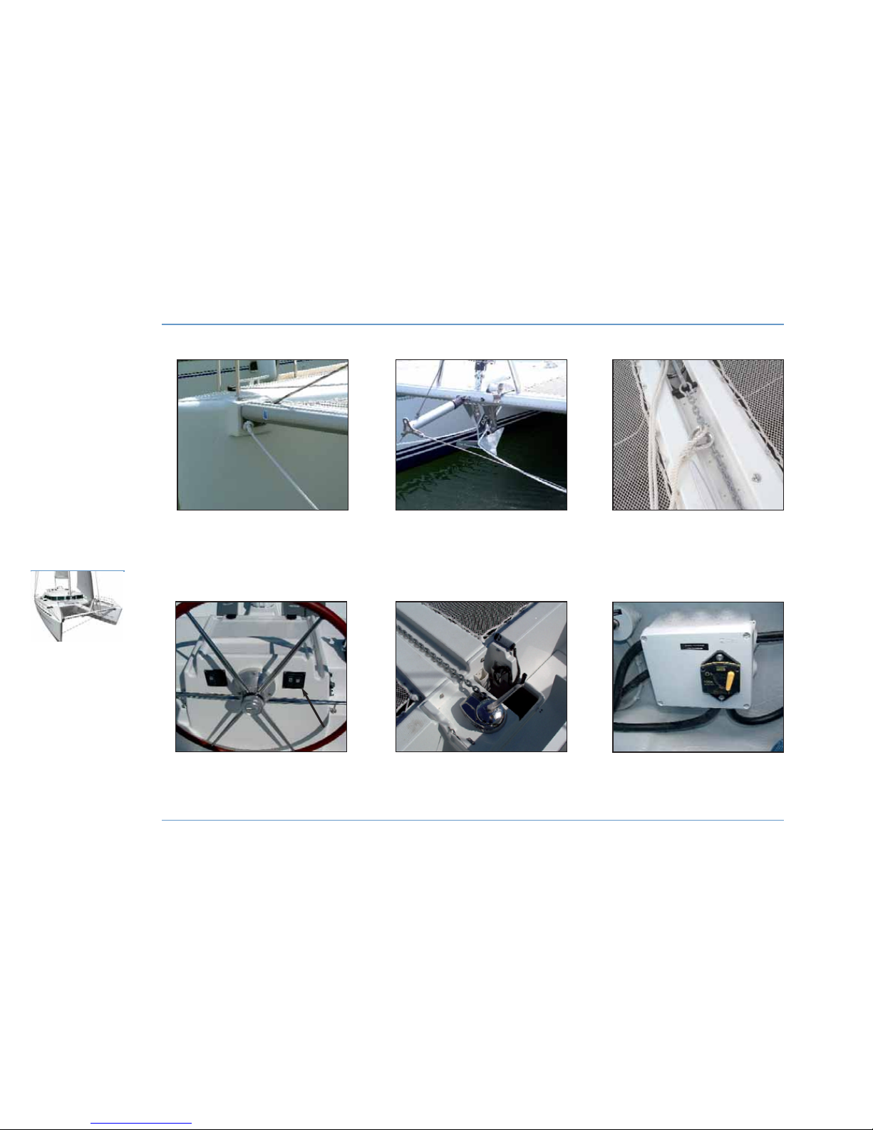
ANCHORING
18
NAVIGATION
LAGOON 44O
WINDLASS CIRCUIT
BREAKER (FORWARD
COCKPIT LOCKER)
SHACKLE THE BRIDLE
TO THE CHAIN
ATTACH THE BRIDLE TO
THE FORWARD BEAM
RUN THE BRIDLE THROUGH
THE BOW ROLLER
WINDLASS
CONTROL
WINDLASS
SWITCH
Page 21

z
WINDLASS ANCHORING
Activate the windlass with the control found in the windlass locker or
from the steering station.
If the port engine is not functioning, the windlass can work on service
batteries (if available) by switching on the port engine ignition only
(the engine alarm will then sound while the windlass is in use).
N.B.: The batteries can be recharged via the generator (optional extra)
if the engines do not start.
z
HOISTING ANCHOR
- Apply the brake on the chain lifter.
- Ensure the chain is properly set on the chain gypsy.
- Slowly advance the vessel using your engine (do not use your
windlass to advance the boat).
- Release the bridle from the chain.
- Lift the anchor completely.
- Visually check the final meters until the anchor makes contact with
the davit.
- Check the position of the anchor on the stem-head fitting.
- Secure the anchor or anchor chain to the cleat.
In the case of electrical failure use the winch handle on the windlass
to lift anchor.
z
MAINTENANCE
After each trip rinse the windlass and dockside line with fresh water.
Refer to the manufacturer's instructions for windlass maintenance at
the beginning or end of the season.
NAVIGATION
19
NAVIGATION
1
LAGOON 44O
WARNING
Windlass operations are dangerous:
- Always keep the anchor line clear and
unencumbered.
- Always proceed with care, using gloves and always
wearing shoes.
WARNING
All anchoring maneuvers using the electric windlass
should be carried out with the port engine running.
Page 22
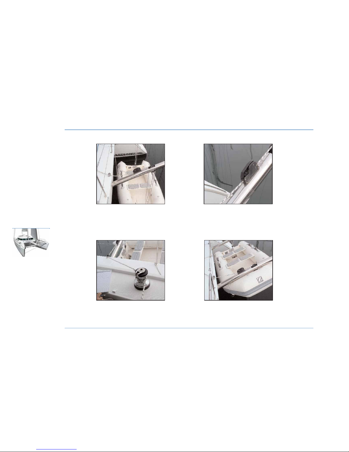
DAVITS
20
NAVIGATION
LAGOON 44O
BLOCKING TENDER
AGAINST THE DAVITS
PULLING UP TENDER
WITH WINCH
ATTACH
DAVIT LINES
DAVIT BLOCKERS
Page 23

Davits (optional extra)
z
INSTALLING A TENDER ONTO THE DAVITS
- Fix the davit line hooks to the forward and aft of the tender.
- Close the blockers found on the davits.
- Pull the bow of the tender up to halfway using the cockpit winch.
- Repeat the operation for the stern.
- Alternatively raise bow and stern until the tender comes into contact
with the davits.
z
LAUNCHING A TENDER FROM THE DAVITS
- Ensure that the blockers on the davits are closed.
- Thread the davit rope attached to the stern of the tender around the
winch (minimum of three turns).
- Open the blocker and let the line feed out until halfway.
- Close the blocker.
- Repeat the procedure for the bow.
- Alternatively lower stern and bow until the tender comes into
contact with the water.
Environment
Do not discharge oil into the sea.
Take every precaution to prevent hydro-fuel overflow when filling the
engine tank.
When in port, only use the onboard toilets if they are equipped with
organic waste reservoirs.
The use of detergents is implicated in the destruction of marine plant
and animal life. Choose fully biodegradable cleaning products.
Do not throw plastic bags and bin bags into the sea. Use the bins
provided for this purpose at ports.
NAVIGATION
21
NAVIGATION
1
LAGOON 44O
RECOMMENDATION
We share a love for the ocean. Help us to preserve
them!
WARNING
Nobody should be aboard the tender during
maneuvers carried out with the davits. Tie up the
tender out of the way during maneuvers.
WARNING
The davits are designed to support a maximum load
of 250 kg and a tender of 3.80 meters in length at
maximum.
WARNING
When under sail remove the tender engine and store
it on board the boat.
Secure the tender according to sea conditions.
Page 24

Page 25

23
LAYING UP . . . . . . . . . . . . . . . . . . . . . . . . . . . . . . . . . . . . . 25
PROTECTION AND MAINTENANCE
. . . . . 25
Winter
Storage
2
Page 26
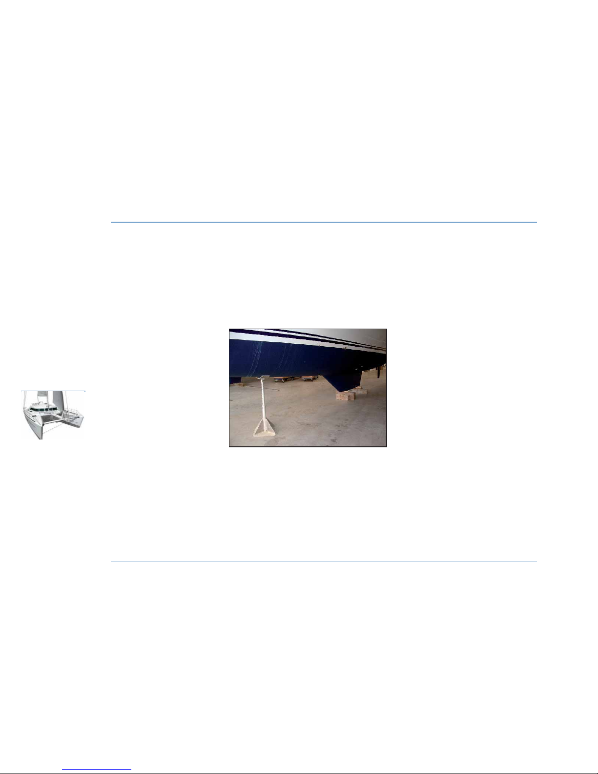
BLOCKING THE BOAT ASHORE
24
WINTER STORAGE
LAGOON 44O
Page 27
Laying up
- Take ashore all the ship's documents, any lines that are not used for
mooring, galley equipment, supplies, clothes, safety equipment,
batteries and gas bottles.
- Check the safety equipment, check expiration dates and have the
life-raft overhauled.
- Take advantage of the laying up to draw up a complete inventory of
equipment.
z
BLOCKING THE BOAT ASHORE
Preparation for each hull:
- A large rectangular wooden block of 1m in length and a tire to be
placed under the stern, across the keel.
- A steel jack-stand of a minimum of 1m in height which will be
placed under the forward part of the forward bulkhead.
Make sure that the aft part of the keel is well-chocked (on its block)
before very carefully lowering the forward section onto the jackstand.
Protection and maintenance
z
INTERIOR
- Drain all the fresh water hoses and rinse them with water and
vinegar (do not use a chlorine based product).
- Lubricate and close all the water inlet valves and thru-hull fittings.
Rinse and completely drain the heads bowls and pumps.
- Retract the sounder and speedometer sensors.
- Seal air inlets as much as possible.
- Install an air dehumidifier in the saloon and leave the cabin and
storage unit doors open (lockers, ice boxes).
- Air the cushions outside for as long as possible before returning
them to the boat, placing them upright on one side to limit contact
surfaces.
z
EXTERIOR
- Thoroughly rinse the hull and deck.
- Lubricate all mechanical and mobile parts with Vaseline (bolts,
hinges, locks etc.).
- Protect all lines and dockside lines against chafing.
- Protect the boat to the highest degree with fenders.
- Make sure the boat is properly moored.
This list of recommendations is not exhaustive. Your dealer can advise
you and carry out the technical maintenance of your boat.
z
ENGINES
WINTER STORAGE
25
WINTER STORAGE
2
LAGOON 44O
RECOMMENDATION
Winter storage of the engines is the domain of
professionals. Storage conditions will depend on
whether the boat is stored afloat or ashore.
Page 28

Page 29

27
RECOMMENDATIONS. . . . . . . . . . . . . . . . 29
STEPPING THE MAST
. . . . . . . . . . . . . . . . 31
Launching
3
Page 30
POSITIONING THE HOISTING BELTS
28
LAUNCHING
LAGOON 44O
Page 31
Recommendations
A lot of skill and care is required to commission your boat for the first
time.
The future proper functioning of your boat and its equipment depends
on the quality of the commissioning operation.
In order to validate the warranty in the event of the failure of certain
equipment, the initial launch and equipment tests must be carried out
by your LAGOON dealer or agent.
z
BEFORE LAUNCHING
- If your boat is to be fitted with a sounder and speedometer, allow for
the relevant fittings and their installation.
- Check the water intake strain box for cleanliness.
- Check the engine and reduction gear oil levels (refer to engine
manual).
- All the optional accessories should be sealed with paste.
- Retract the speedometer into its housing (it may be damaged by the
handling belts).
- Turn off all the water inlet and drain valves (sink, washbasin, heads
and engine).
z
HOISTING
Tie off the vessel fore and aft with fenders.
Prepare:
- 2 belts (minimum 11 meters).
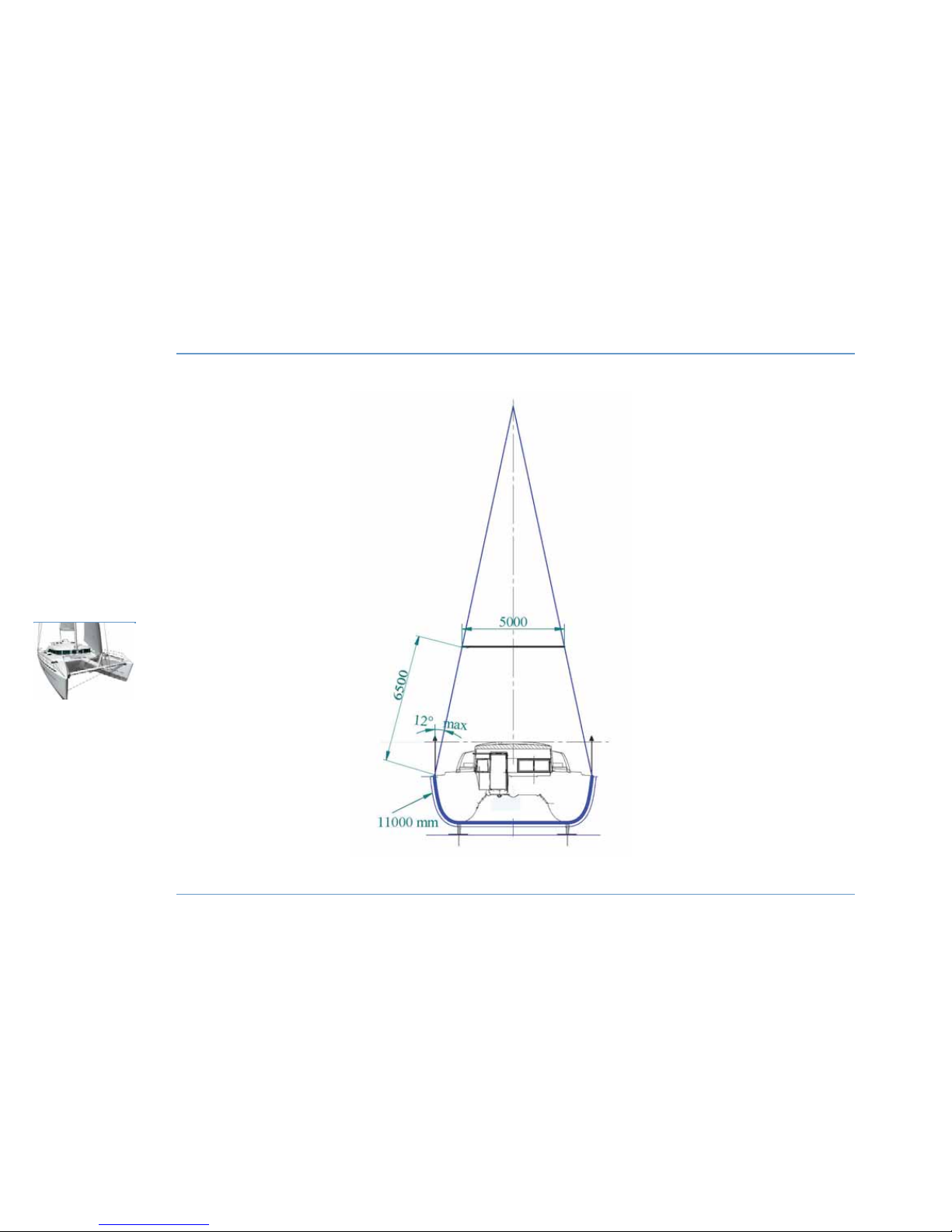
- 4 slings (see diagram opposite).
- Attach the 4 slings to the belts.
LAUNCHING
29
LAUNCHING
3
LAGOON 44O
RECOMMENDATION
All future maintenance should be carried out with
the greatest care by professionals.
If the LAGOON boatyard is not involved in
maintenance operations, your guarantee will not
cover any incidents linked to handling errors.
Page 32
PACKING
30
LAUNCHING
LAGOON 44O
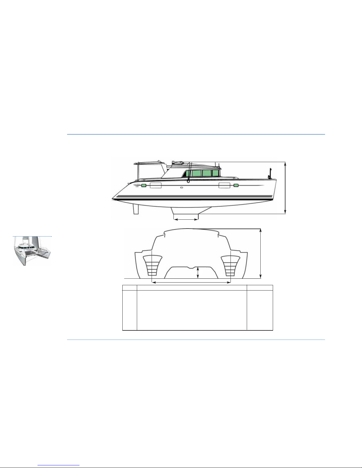
Mark Identification Size (m)
A Width between hull centers 5,30
B Height clearance (without mast or appendices) 3,34
C Waterline height under nacelle 0,67 - 0,81
D Vessel height on its keels (without mast or appendices) 4,64
E Length of keels 2,25
Length of boom 6,80
Length of Europe mast 19,20
FURTHER INFORMATION RELATIVE TO THAT GIVEN IN THE GENERAL SPECIFICATIONS CHAPTER
A
B
E
D
C
Page 33
- Put it slightly under tension; the sling hooks should be situated at
the boat's centre of gravity, either in the longitudinal centre or plumb
with the shroud chain-plates in the transverse plane.
Hoist gently, and control the movement of the boat with dock lines.
z
AFTER LAUNCHING
- Check the sounder and speedometer fittings for tightness if
necessary.
- Open the valves and make sure that they are watertight.
Before starting the engine, refer to the MOTORIZATION chapter.
Stepping the mast
If later you have to step the mast anywhere other than at your
LAGOON dealer, proceed as follows:
z
BEFORE STEPPING THE MAST
- Protect the mast against possible chafing by the crane hook and
cable.
- Tie down the shrouds and all the riggings to the base of the mast
with lashing long enough to guide the mast heel when stepping the
mast.
- Protect the spreader end fittings and the roller furler drum.
- Put around the mast a line of about 1.50 m with an eye and thimble
at both ends and covered with rags; place this rope over the second
level of cross trees.
- Link together both thimbles (in front of the mast) with a shackle
large enough to receive the crane hook.
- Raise the whole till it is taut under the spreader bases.
z
DURING MAST STEPPING
- Take the necessary steps to avoid damaging the mast head
equipment.
- Use the backstay and lashing at the base of the mast to control the
handling.
- Engage the electrical harness in the mast base.
- Ensure the base of the mast bears fully on its base plate.
LAUNCHING
31
LAUNCHING
3
LAGOON 44O
DANGER
Do not stay on board or under the boat during
hoisting.
RECOMMENDATION
Never place belts or fenders in contact with the
large glass windows in the hulls.
Page 34
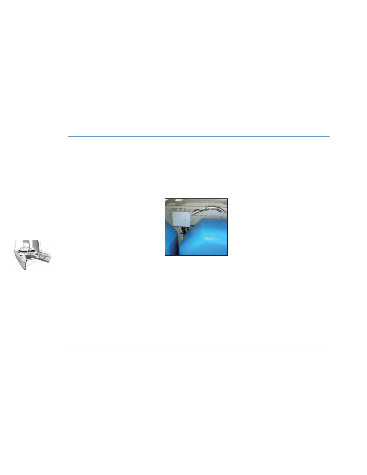
32
LAUNCHING
LAGOON 44O
MAST
JUNCTION BOX
Page 35
z
AFTER MAST STEPPING
- Lubricate all the turnbuckles (see recommendations in the RIGGING
chapter).
- Tension the rigging (refer to RIGGING chapter for settings).
- Reconnect the electrical cables in the junction box at the base of the
mast located in the forward cockpit locker after running the cables
through the gooseneck located at the front of the mast (see
ELECTRICITY chapter).
- Carefully check the tightness of the turnbuckle cotter pins, and
protect with adhesive tape.
- Replace the boom and re-lead all the lines.
z
DISMASTING
Proceed by carrying out the operations recommended for stepping the
mast in reverse order, taking care to mark the line locations with
stickers.
LAUNCHING
33
LAUNCHING
3
LAGOON 44O
RECOMMENDATION
Re-adjust the mast after a few miles.
RECOMMENDATION
Before all dismasting operation, remember to
disconnect the electric cables.
Pull gently while guiding the cables.
Page 36

Page 37

35
CONSTRUCTION . . . . . . . . . . . . . . . . . . . . . . . 37
MAINTENANCE
. . . . . . . . . . . . . . . . . . . . . . . . . 37
HAUL OUT
. . . . . . . . . . . . . . . . . . . . . . . . . . . . . . . . 37
GEL-COAT REPAIR. . . . . . . . . . . . . . . . . . . . 39
STEERING GEAR. . . . . . . . . . . . . . . . . . . . . . . 39
DECK WASH PUMP . . . . . . . . . . . . . . . . . . . 41
Hull
& deck
4
Page 38
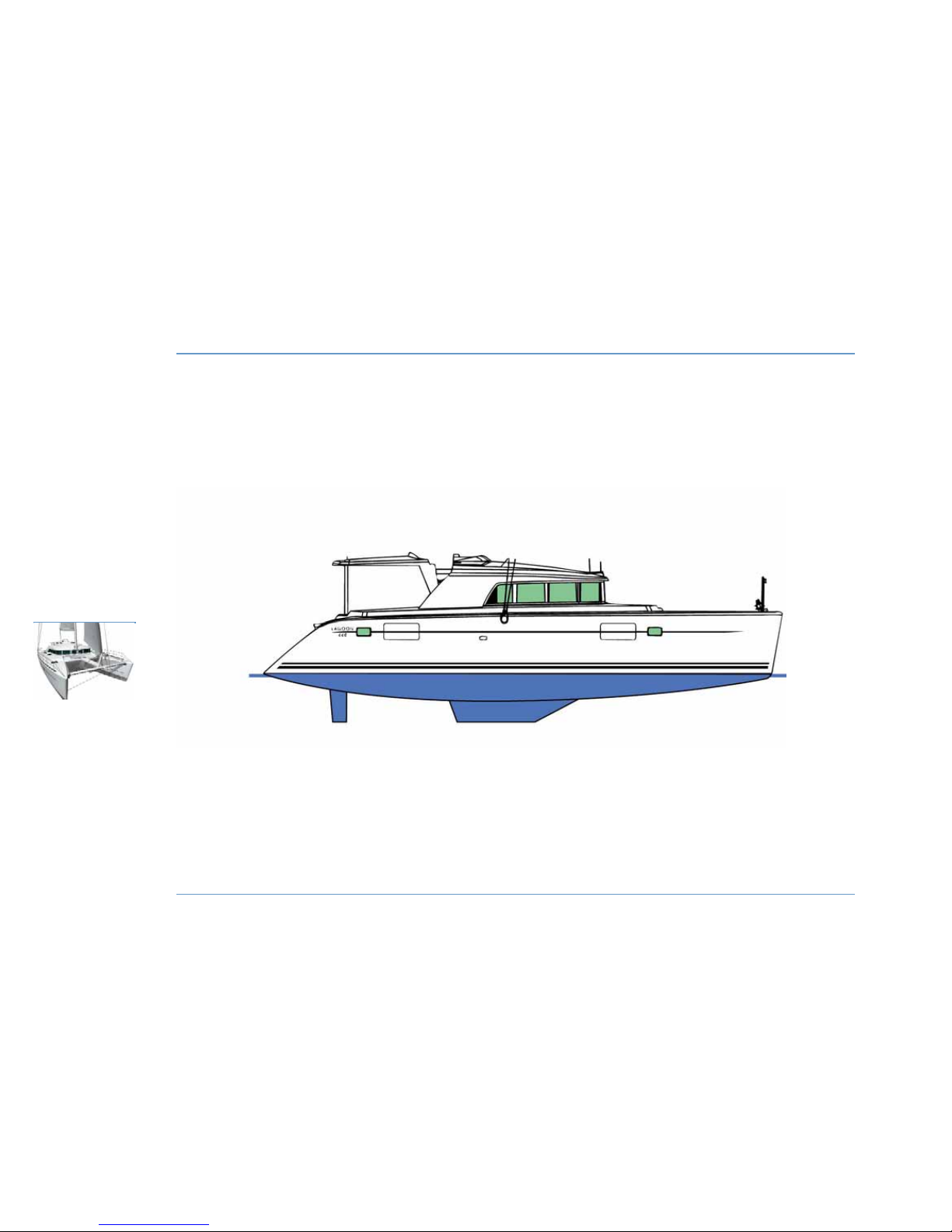
HAUL OUT
36
HULL
& DECK
LAGOON 44O
Submerged area (including appendices): 63 m2.
Page 39
Construction
The LAGOON 440 is built of balsawood sandwich (monolithic below
the water line), polyester resin and vinyl-ester; the counter-moulds
are monolithic and the partitions are made of laminated plywood.
The nacelle and deck are of balsawood sandwich composite.
Maintenance
The materials and equipment of your boat have been selected for
their high quality and performance and for their ease of maintenance.
However you must carry out a small amount of maintenance in order
to protect your boat from external elements (salt, sun, corrosion...).
Clean your boat preferably on shore with fresh water.
Use as few cleaning products as possible.
Do not use solvents or aggressive detergents.
Do not discharge cleaning products into the sea.
Regularly brush the deck with a degreasing cleanser and fresh water.
DECK FITTINGS
- Thoroughly rinse all your equipment with fresh water.
- Periodically lubricate blocks, sheaves, turnbuckles, winches, tracks
and travelers with water-repellent grease.
- Stainless steel that is showing small spots or blisters of rust should
be cleaned and polished with a chrome and steel renovator.
EXTERNAL TEAK FITTINGS / TECK DECK
Regularly clean all exterior wood with fresh water using a sponge (if
necessary some mild soap may be added).
PLEXIGLASS
- Rinse Plexiglass with fresh water.
- Polish with a soft cloth soaked in liquid paraffin.
- Use polishing paste to remove scratches.
Haul out
Applying a tin-free anti-fouling paint every year will avoid the need for
tedious and frequent haul-outs. An epoxy undercoat is recommended.
You are reminded that sanding before applying antifouling paint
attacks the gel coat and impairs its durability.
Polishing will restore your boat's original shine. If a persistent and
isolated problem arises, contact your dealer.
HULL & DECK
37
HULL
& DECK
4
LAGOON 44O
RECOMMENDATION
We strongly advise against the use of pressure
washers.
Do not use hot water or steam.
Page 40
STEERING GEAR
38
HULL
& DECK
LAGOON 44O
1
2
3
4
5
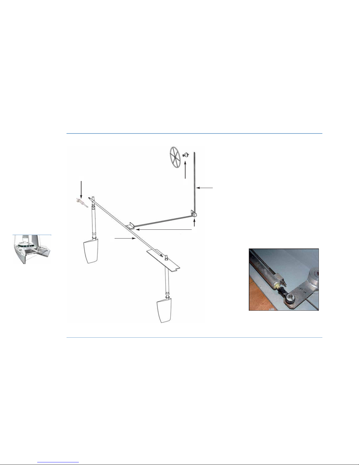
1 - Steering gear.
2 - Cables.
3 - Cable sheave.
4 - Connecting rod.
5 - Autopilot ram (optional extra).
CABLE TENSION
SYSTEM
Page 41

Gel-coat repair
PROPORTIONS
Our products contain an accelerator. You simply need to add the
catalyst (a colorless liquid). The usual proportion is 2%.
The gel setting time (working time) is about 30 minutes, complete
hardening takes about 10 hours.
APPLICATION
- To fill a blister hole or a scratch, sand and clean the area with
acetone.
- Prepare the necessary amount of gel coat, preferably on a glass
plate.
- Apply the product with a spatula or a nib in a layer thick enough to
enable further sanding.
- In order to even out minor touch-ups on smooth surfaces, stick
cellophane tape (or better, Mylar tape) on the freshly applied gel coat.
- Remove sellotape after hardening.
- To obtain a high shine finish, sand with extra fine paper and water,
then polish.
STORAGE
Store gel coat components in a cool, dry and dark place.
The components can be kept for a maximum of 6 months.
Polyester products are flammable, so take the usual precautions.
CLEANING YOUR TOOLS
Clean your tools with acetone.
Steering gear
The steering system is accessed via the engine compartment.
- Regularly check tightening.
- Do not over-tighten the steering cables.
- Grease all elements.
Treat nylon, ertalon or Teflon bushings with WD40 only.
Proper settings result in gentle steering resistance, without hard
points and without looseness.
HULL & DECK
39
HULL
& DECK
4
LAGOON 44O
WARNING
Please respect the following conditions for
successful repairs:
- Dry weather.
- Temperature between 15 and 25°C.
DANGER
The catalyst is a dangerous product:
- Keep it out of the reach of children.
- Avoid any contact with skin and mucous.
- Wash with soapy water and rinse thoroughly.
Page 42
DECK WASH PUMP
40
HULL
& DECK
LAGOON 44O
2
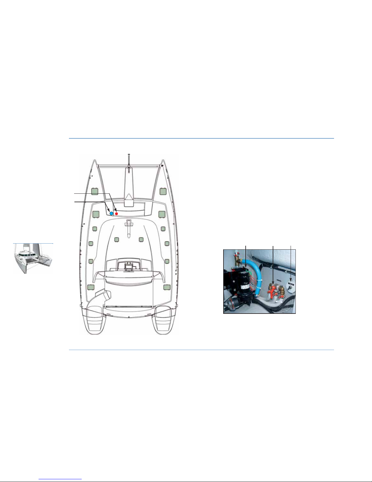
1 - Deck wash pump.
2 - Three-way valve for fresh/sea water.
3 - Switch.
1
1
2
3
Page 43
Deck wash pump (optional extra)
The deck wash pump is located in the forward port cockpit locker.
It supplies sea or fresh water from the port tanks (access to the
selector valve through the forward port cockpit locker).
An activating switch is located next to the deck wash pump. It is on
12 V supply as soon as the boat's power is turned on (Service battery
switch).
HULL & DECK
41
HULL
& DECK
4
LAGOON 44O
Page 44

Page 45

43
INTERIOR MAINTENANCE . . . . . . . . . . . . . . . . . . . . 45
FABRICS
. . . . . . . . . . . . . . . . . . . . . . . . . . . . . . . . . . . . . . . . . . . . 45
COCKPIT TABLE
. . . . . . . . . . . . . . . . . . . . . . . . . . . . . . . . . 47
PORTHOLES AND HATCHES
. . . . . . . . . . . . . . . . 47
WASHING MACHINE - DISHWASHER . . . . 49
HEATING
. . . . . . . . . . . . . . . . . . . . . . . . . . . . . . . . . . . . . . . . . . . 49
AIR CONDITIONING
. . . . . . . . . . . . . . . . . . . . . . . . . . . . . 51
Layouts
5
Page 46
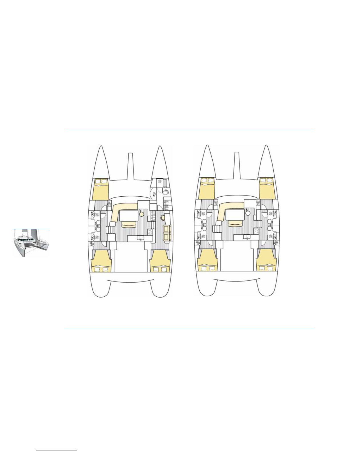
LAYOUTS
44
LAYOUTS
LAGOON 44O
3 cabin version. 4 cabin version.
Page 47
Interior maintenance
- Take advantage of nice weather to air the sofa and berth cushions.
- Stand the cushions vertically if you leave the boat for a prolonged
period.
- Use sun shades to protect the inside of the boat from UV rays.
- Ensure the bilges are kept clean and dry.
z
INTERIOR VARNISH
- Rinse interior varnish with fresh water mixed with spot removing
furniture shampoo.
- Polish interior varnish with chamois leather.
Fabrics
ADVICE: Mark each cover and foam pad when dismantling for easy
identification.
z
STAIN REMOVING
- Remove as much of the stain as you can with the blade of a knife
(starting from the edge and moving towards the centre).
- Dab with a dry cloth.
- Remove the stain using a clean cloth dipped in solvent. Never pour
solvent directly onto the stain.
- Rub with a clean, dry cloth.
- Brush the fabric against the grain.
- Vacuum the fabric when dry.
PVC AND COATED FABRICS
- Use a sponge and soapy water (household soap).
- For persistent stains, dab with a cloth soaked in white spirit, do not
rub.
JACQUARD 100% POLYESTER / DRALON
If the fabric cannot be removed:
- Vacuum.
- Clean with synthetic foam (see the product's instructions for use).
If the fabric can be removed:
- Hand-wash at 30° with standard washing powder.
Both types of fabric can be dry-cleaned. Remove stains as soon as
possible with a damp cloth.
LAYOUTS
45
LAYOUTS
5
LAGOON 44O
RECOMMENDATION
Use as few cleaning products as possible.
Do not discharge cleaning products into the sea.
RECOMMENDATION
For PVC fabrics do not use solvents or solvent based
products.
Page 48
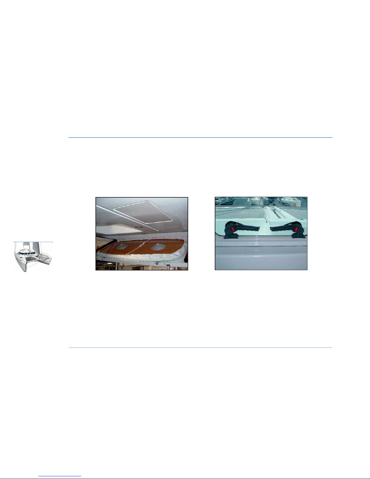
COCKPIT TABLE - DECK HATCH
46
LAYOUTS
LAGOON 44O
LOCKING
DECK HATCH
(Left-hand handle button in open position.)
(Right-hand handle button in closed position.)
STOWING
COCKPIT TABLE
Page 49
JACQUARD COTTON
- Dry clean.
- Do not iron.
- Do not use bleach.
- Remove stains with fractionated petrol.
ALCANTARA
- Wash in warm water with pH-neutral soap.
- Leave to dry naturally.
- Dry clean with perchloroethylene.
LEATHER
- Use a leather cream for day-to-day care.
- Do not use detergent.
- Do not use silicone-based products.
- Clean with a sponge and soapy water.
- Remove ball point pen marks with methylated spirit.
- Remove grease stains with an absorbent powder (e.g. talcum
powder).
Cockpit table
The cockpit ceiling is used for stowing the outside table.
To install the cockpit table release the ceiling and remove the table
while being careful of movement of the boat.
The two tables (saloon and cockpit) are interchangeable.
Carefully fasten the ceiling back into place after removing or replacing
the cockpit table.
Portholes and deck hatches
The portholes and deck hatches are equipped with latch systems to
keep them in a closed position.
At mooring, intermediate opening positions allow for airing of the
boat.
LAYOUTS
47
LAYOUTS
5
LAGOON 44O
Page 50
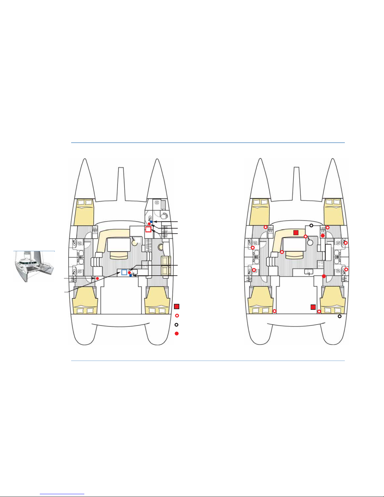
WASHING MACHINE - DISHWASHER - HEATING
48
LAYOUTS
LAGOON 44O
Diesel fuel heater 4000 watts
Forced air outlet
Heater exhaust outlet
Starting and temperature control
2
4
3
1
6
HEATING
WASHING MACHINE - DISHWASHER
1 - Electrical protection fuses.
2 - Dishwasher (110 V - 220 V).
3 - Water inlet valve for washing machine.
4 - Drain valve for washing machine.
5 - Washing machine (110 V - 220 V).
6 - Drain valve for dishwasher.
7 - Water inlet valve for dishwasher.
7
4
5
The positions are the same for the other layout version.
Page 51
Washing machine - dishwasher (optional
extras)
- Make sure that there is sufficient fresh water before using the
washing machine or dishwasher.
- Open the water supply and drain valves of the respective machine.
Water supply:
Washing machine: under the washbasin in the forward starboard
toilet.
Dishwasher: under the galley sink.
Drainage:
Washing machine: under the washbasin in the forward starboard
toilet.
Dishwasher: connected to the galley sink drains.
- Connect the shore power supply or start the generator (see
ELECTRICITY chapter).
- Switch on the circuit breakers in the port aft cabin cupboard.
- Switch on the relevant machine.
For use and maintenance of the washing machine or dishwasher refer
to their relevant instruction guide.
Heating (optional extra)
The heating system works on 12 V.
It consists of two 4000 W heaters located under the forward saloon
bench seat and in the starboard aft cockpit locker.
The heaters are supplied with diesel from the starboard tank.
To operate the system:
- The system is supplied with 12 V current as soon as the boat power
is switched on (Service battery switch).
- Switch on the heaters with their controls located in the starboard aft
cabin and in the saloon at the steering station.
- Adjust to the required temperature.
For use and maintenance of the heating refer to the instruction guide.
LAYOUTS
49
LAYOUTS
5
LAGOON 44O
Page 52
50
LAYOUTS
LAGOON 44O
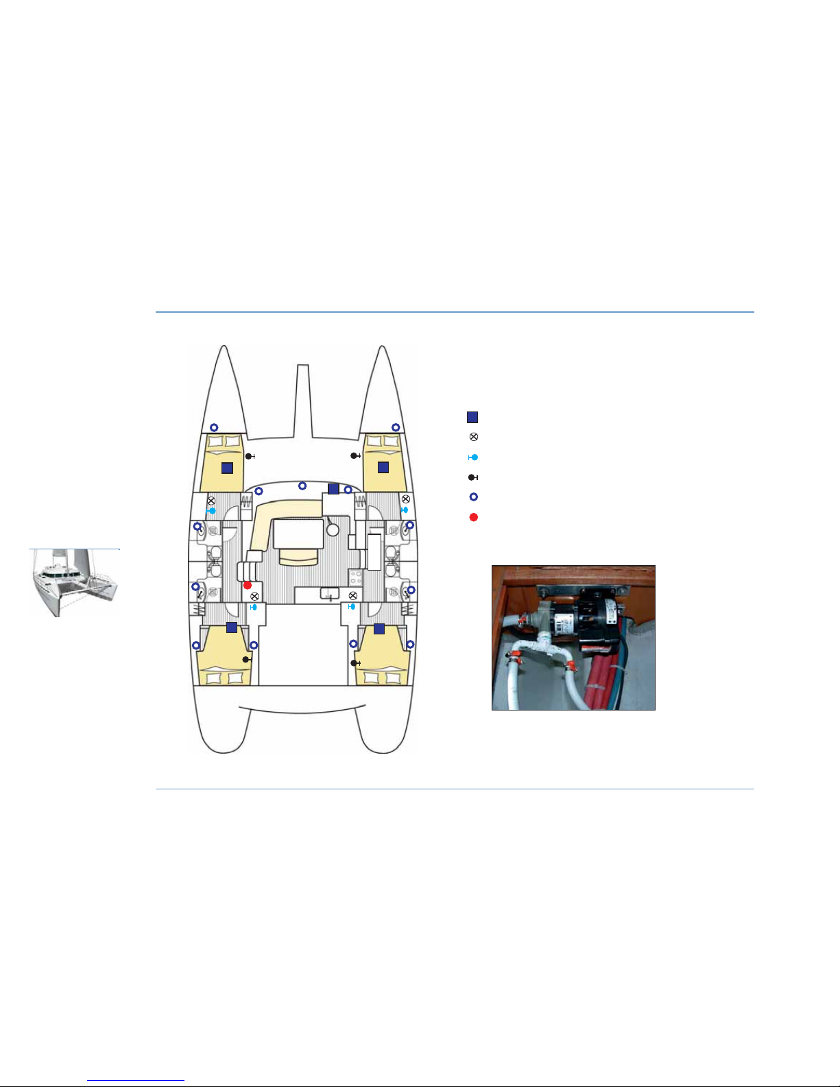
AIR CONDITIONING
Compressor
Sea water pump
Water supply valve for pumps
Drain valve for compressor
Air outlet
Electrical fuse protection
POWER: 44 000 BTU for the Charter version.
46 000 BTU for the Owner version.
SEA WATER PUMP FOR
AIR CONDITIONING
Page 53
Air conditioning (optional extra)
The air conditioning system works on 110 V - 220 V.
To operate the system:
- Open the pump water supply valves (one in each hull for the supply
of several compressors).
- Open the compressor drain valves (2 in each hull).
- Connect the specific air conditioning shore power supply (220 V
only) or start the generator (see ELECTRICITY chapter).
- On the electrical panel select the air conditioning supply on QUAI or
GENERATEUR.
- Turn on the mains switch (AC-MAIN) for the air conditioning on the
electrical panel.
- Operate the air conditioning units on the electrical panel. Wait 30
seconds between the starting of each unit.
- Adjust to the required temperature and ventilation on the air
conditioning controls in the respective areas.
For use and maintenance of the system refer to the instruction guide.
LAYOUTS
51
LAYOUTS
5
LAGOON 44O
Page 54

Page 55

53
Electricity
6
BATTERIES/CIRCUIT BREAKER. . . 55
OPERATION
. . . . . . . . . . . . . . . . . . . . . . . . . . . . . . 57
110 V - 220 V CIRCUIT . . . . . . . . . . . . . . 59
SERVICE COMPARTMENT. . . . . . . . . . 59
GENERATOR . . . . . . . . . . . . . . . . . . . . . . . . . . . . .
61
BATTERY CHARGER
. . . . . . . . . . . . . . . . . . 61
INVERTER. . . . . . . . . . . . . . . . . . . . . . . . . . . . . . . . . 61
SHORE POWER SUPPLY. . . . . . . . . . . . 63
MAST WIRE HARNESS. . . . . . . . . . . . . . . 63
ELECTRONICS. . . . . . . . . . . . . . . . . . . . . . . . . . 63
APPENDIX. . . . . . . . . . . . . . . . . . . . . . . . . . . . . . . . 64
Page 56
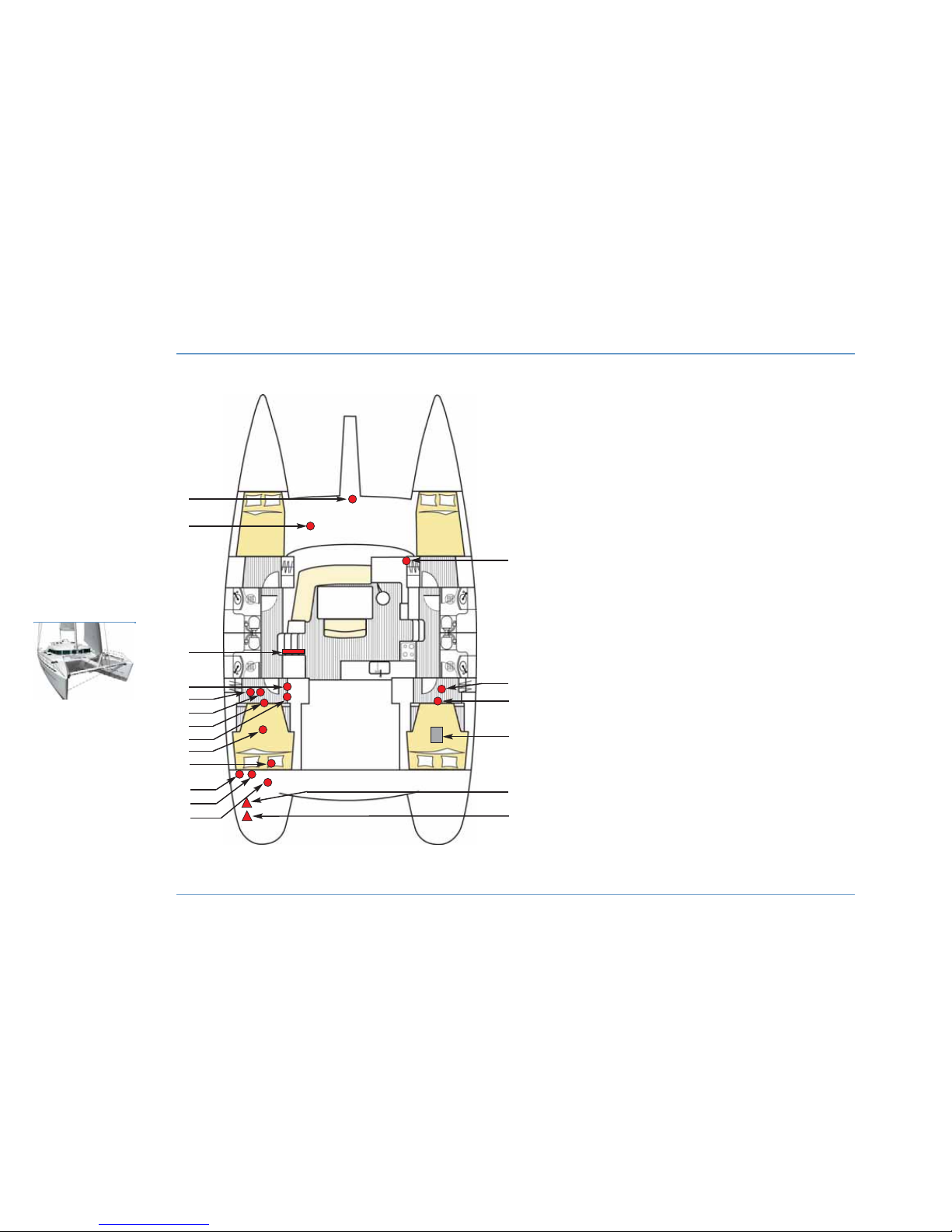
ELECTRICS LAYOUT
54
ELECTRICITY
LAGOON 44O
18
19
17
16
1
2
3
4
10
11
1 - Windlass.
2 - Windlass circuit breaker.
3 - Electrical panel.
4 - 110 V / 220 V circuit breakers + inverter.
5 - 5th battery option.
6 - Engine battery.
7 - Battery switches.
8 - Washing machine / dishwasher circuit breaker.
9 - Service battery + 4th battery (option).
10 - Automatic pilot calculator.
11 - Shore power supply circuit breaker.
12 - Air conditioning shore power supply circuit breaker.
13 - Battery charger.
14 - Electric compressor fridge.
15 - Engine battery.
16 - Battery switches.
17 - Water heater.
18 - Shore power supply.
19 - Air conditioning shore power supply.
12
13
Locations are the same for the other layout version.
5
7
14
6
8
9
15
Page 57

A battery monitor (DC meter on the electrical panel) enables control
of the charge, voltage and depletion rate of the service batteries and
of the generator (optional extra).
For its use see the instruction guide.
Always check the battery and charge system condition before you put
out to sea.
Keep the batteries clean and dry in order to avoid premature wear.
Have the acidity level of the battery checked if left unused for a
prolonged period. Check the level regularly.
Tighten and maintain the terminal connectors by lubricating them
regularly with Vaseline.
Batteries and circuit breakers
The electricity onboard is 12 V DC.
The electrical system consists of service batteries. The batteries
supply power to all the functions on board (see SPECIFICATIONS
chapter for battery capacity).
The general 12 V system is turned on by switching to ON the battery
switches located in the port and starboard aft cabins.
z
MAINTENANCE
Keep the batteries charged (essential to ensure longevity).
It is possible to operate with the battery store charged to 80% on the
condition that the batteries are charged weekly to 100%.
Never run batteries down below 70% of their nominal capacity.
Use the battery charger when in a marina to ensure you begin each
trip with properly charged batteries.
ELECTRICITY
55
ELECTRICITY
6
LAGOON 44O
WARNING
A damaged battery will never recover its original
capacity.
The service batteries should be charged to their
maximum.
Page 58
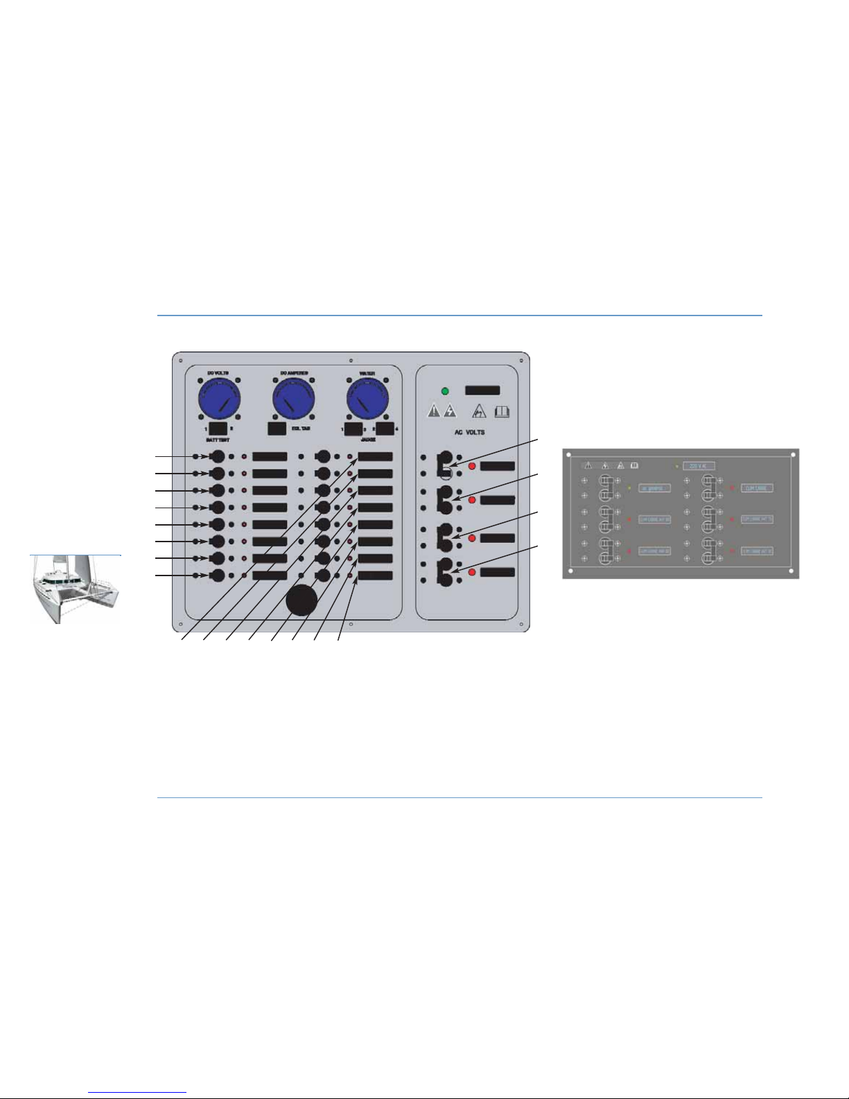
ELECTRICAL PANELS
56
ELECTRICITY
LAGOON 44O
1 - Navigation lights.
2 - Mooring lights.
3 - Steaming light.
4 - Deck light.
5 - Interior lighting.
6 - Saloon lighting.
7 - Instrument lighting.
2
1
3
4
5
6
7
8
10
9
11
12 13 14 15 16
17
18
19
20
15 - Port bilge pump.
16 - Miscellaneous 2.
17 - 220 V AC sockets.
18 - 220 V AC battery charger.
19 - 220 V AC water heater.
20 - 220 V AC miscellaneous.
8 - 12 V DC socket.
9 - Water pump.
10 - Starboard bilge pump.
11 - Refrigerator.
12 - Confort (Waste water pump).
13 - Navigation station.
14 - VHF.
AIR CONDITIONING PANEL
Page 59

Use of 12 V circuit
In the event of an electric appliance is not receiving power, check:
- The main power supply.
- The switches and circuit breakers on the line
- The relevant electrical unit.
ELECTRICITY
57
ELECTRICITY
6
LAGOON 44O
RECOMMENDATION
Never leave the boat unattended when the electrical
system is switched on (except the safety equipment
directly connected to the battery and protected by a
circuit breaker).
WARNING
Never work on a live electrical circuit.
RECOMMENDATION
- Never modify an electric fixture or the relevant
layouts yourself.
- Call in a technician skilled in marine electricity to
carry out any electrical modifications.
- Never change the breaking capacity (amperage) of
the excess current safety devices.
- Never install or replace any electric appliances (or
any electrical equipment) by components exceeding
the capacity (amperage) of the circuit (wattage for
bulbs).
Page 60
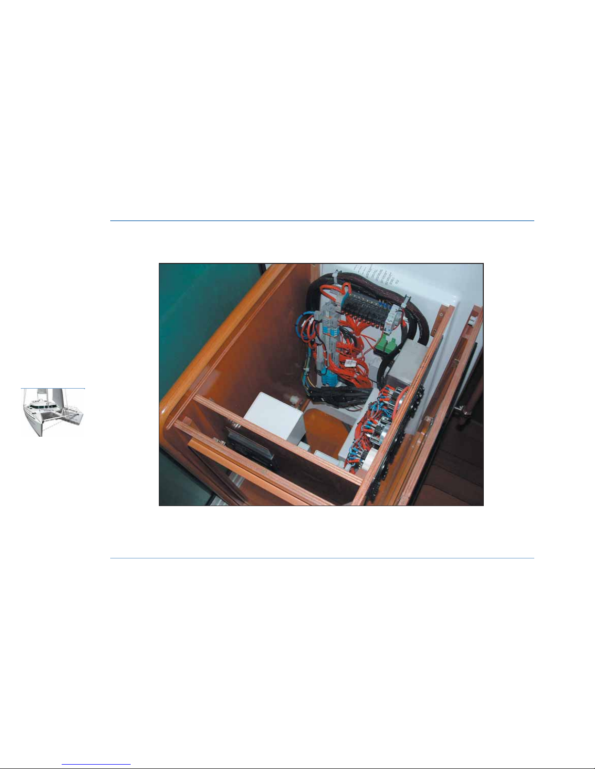
SERVICE COMPARTMENT
58
ELECTRICITY
LAGOON 44O
LOCATED BEHIND THE ELECTRICAL PANEL
Page 61

110 V - 220 V Circuit
z
SWITCHING ON DEVICES FUNCTIONING ON 110 V - 220 V
To use appliances that work on 110 V - 220 V (washing machine,
water-maker, etc.), proceed as follows:
- Make sure that the appliances are OFF on the electrical panel.
- Switch to the 110 V - 220 V source (start the generator or plug into
the shore power supply).
- Select the proper source on the electrical panel for it to supply the
electrical panel.
- Switch on the circuit breaker for the appliance to be used (washing
machine, water-maker, etc.) on the electrical panel.
Once the above has been carried out, turn on the appliance using its
own controls.
For air conditioning, wait 10 to 15 seconds between turning on each
unit (in order to allow the generator to stabilize and to deliver the
necessary power for switching on).
z
SWITCHING OFF DEVICES FUNCTIONING ON 110 V - 220 V
To turn off appliances functioning on 110 V - 220 V (washing machine, watermaker, etc.), proceed as follows:
- Stop the apparatus using its own controls.
To stop 110 V - 220 V equipment wait 10 to 15 seconds after turning
off each device (in order to allow the generator to stabilize).
- Switch off the circuit breaker of the relevant apparatus on the
electrical panel.
- Turn the 110 V - 220 V source selector to OFF (generator or shore
power supply).
- Stop the generator or unplug the shore power supply.
z
PROTECTION
Connect the metallic covers or boxes of the electric appliances that
are installed to the ground conductor of the boat (green conductor
with yellow stripes).
Service compartment
The service compartment where the fuses are located is situated
behind the electrical panel. To access this area lift up the plate above
the electrical panel in order to unclip it (2 clips), then pull it towards
you to remove the plate from the end groove into which it is fitted.
ELECTRICITY
59
ELECTRICITY
6
LAGOON 44O
WARNING
Before turning the 110 V - 220 V source selector to
OFF, ensure that no other appliance is in use
(danger of an electric arc which can destroy the
switch and damage the generator).
Page 62
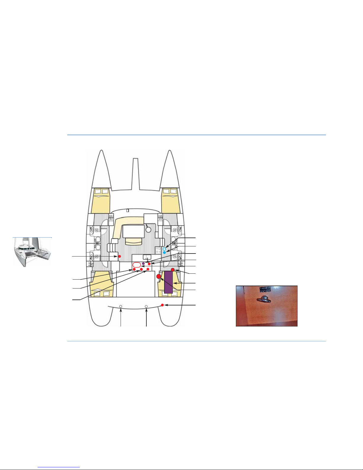
GENERATOR - DIESEL TRANSFER PUMP
60
ELECTRICITY
LAGOON 44O
PULL-SWITCH
FOR TRANSFER
4
12
5
13
11
6
7
9
10
3
1
15 14
2
1 - Remote generator control.
2 - Circuit cutout.
3 - Exhaust hose.
4 - Water/gas separator.
5 - Seawater inlet.
6 - Seawater filter.
7 - Fuel filter for generator.
8 - Generator battery.
9 - Generator.
10 - Diesel valve.
11 - Fuel tank.
12 - Pull-switch for transfer to port fuel tank.
13 - Diesel feeding pump.
14 - Hot air extraction.
15 - Fresh air suction.
8
Page 63
Generator (optional extra)
z
GENERATOR
The generator is located in the central cockpit locker.
Its function is to re-supply the batteries via the chargers and to supply
110 V - 220 V electricity on board.
The generator is supplied by the tank in the starboard hull.
The generator is started either at the generator itself or by the remote
control on the electrical panel after opening of the fuel valve
(starboard aft cabin) followed by the seawater cooling valve (access
under the floor in the starboard gangway).
Concerning use and maintenance of the generator, refer to its
instructions.
z
PULL-SWITCH FOR TRANSFER (OPTIONAL EXTRA)
Use the pull-switch found at the foot of the std berth to change over
from one tank to the other.
Battery charger (optional extra)
The battery charger can be used with shore power supply or with the
generator in use.
It can be accessed through the port engine compartment.
- Turn on the charger with the circuit breaker on the electrical panel.
Concerning use and maintenance of the charger refer to its
instructions.
Inverter (optional extra)
The inverter enables 220 V equipment to operate from 12 V supply.
It is located in the aft beam (access through the port engine cover).
- Turn on the inverter with the circuit breaker on the electrical panel.
For use and maintenance of the inverter refer to its instructions.
ELECTRICITY
61
ELECTRICITY
6
LAGOON 44O
Page 64
62
ELECTRICITY
LAGOON 44O
Page 65
Mast wire harness
During mast-stepping insert the cables through the base of the mast.
The connection is made at the switch box on the mast bulkhead. See
LAUNCHING chapter.
Electronics
Do not install electronic instruments or repeaters less than 1.5 m
away from the radio loudspeakers, if your boat has them.
Do not place the autopilot compass less than 0.5 m away from the
electrical harnesses.
z
ELECTRONICS PACKS (OPTIONAL EXTRAS)
Different electronics packs are offered on option.
ELECTRICITY
63
ELECTRICITY
6
LAGOON 44O
RECOMMENDATION
For your electrical requirements, we recommend
you consult a specialist or our network of
technicians.
Shore power supply
RECOMMENDATION
In order to reduce the risk of electric shock and fire:
- Before you plug in or unplug the boat/shore power
supply cable, switch off the shut off device
connected on the shore supply side.
- Connect the boat/shore supply cable in the boat
before connecting it to the shore supply socket.
- Unplug the boat/shore supply cable on shore first.
Close the shore socket cover.
- Do not modify the connections of the boat/shore
supply cable.
DANGER
Never leave the extremity of a boat/shore power
supply cable hanging in the water - it could create
an electrical field liable to injure or kill any nearby
swimmers.
Page 66
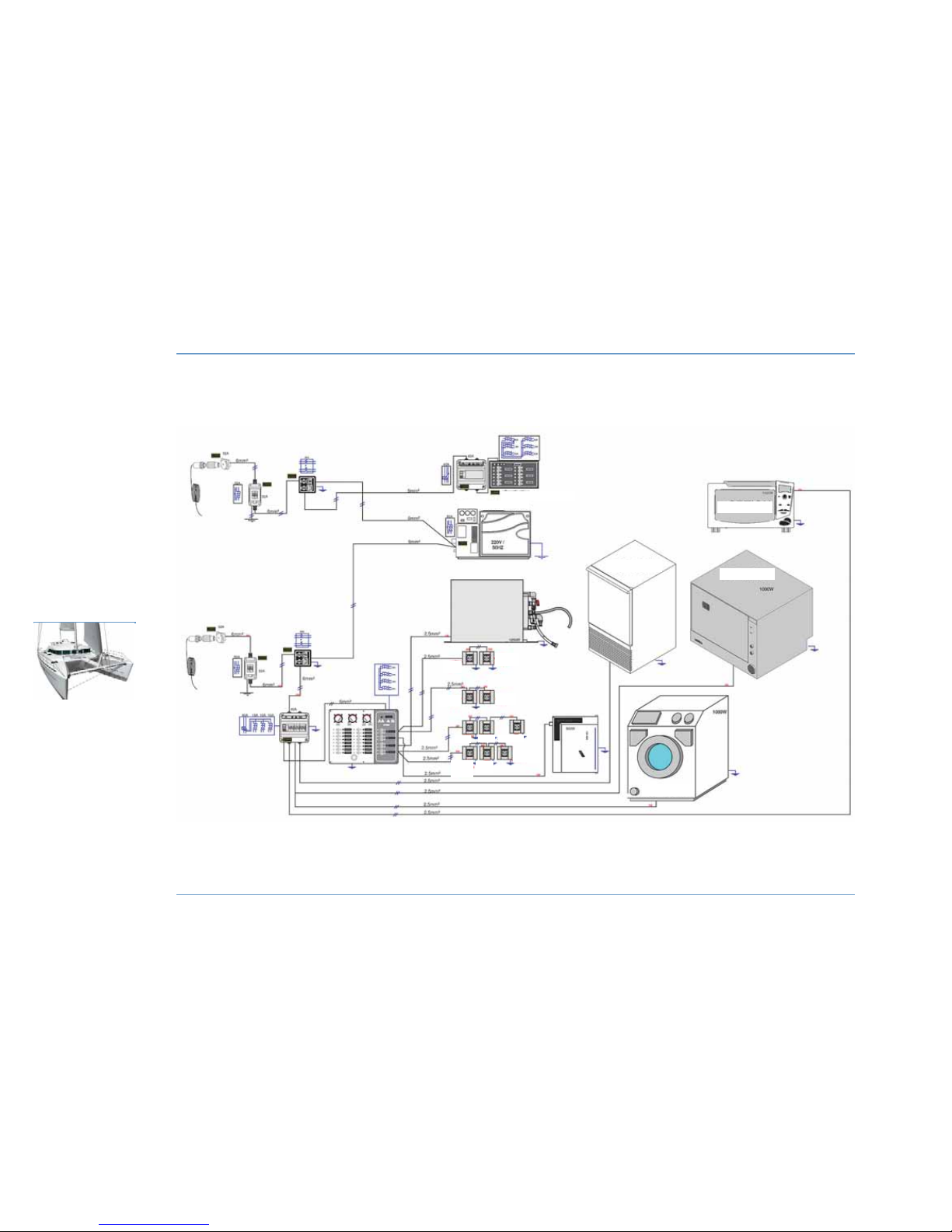
APPENDIX - 220 V DIAGRAM
64
ELECTRICITY
LAGOON 44O
OPTIONAL
OPTIONAL
OPTIONAL
OPTIONAL
Air conditioning OPTIONAL EXTRA
Electricity generator 9.5 KVA
Port aft
cabin
Port fwd
cabin
Stbd fwd
cabin
Stbd aft
cabin
Service
compartment
Galley
Electrical
panel
socket
TV
Socket
Galley
Chart table
Page 67
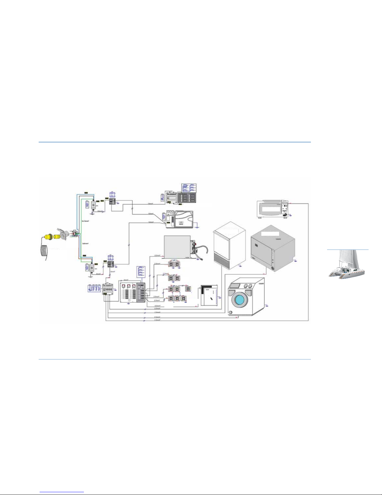
APPENDIX - 110 V DIAGRAM
65
ELECTRICITY
6
LAGOON 44O
OPTIONAL
OPTIONAL
OPTIONAL
OPTIONAL
4 x 10 mm2
cable
Air conditioning OPTIONAL EXTRA
Electricity generator 9.5 KVA
Port aft
cabin
Port fwd
cabin
Stbd fwd
cabin
Stbd aft
cabin
Service
compartment
Galley
Electrical
panel
socket
TV
Socket
Galley
Chart table
Rear view of
shore power
supply
Page 68
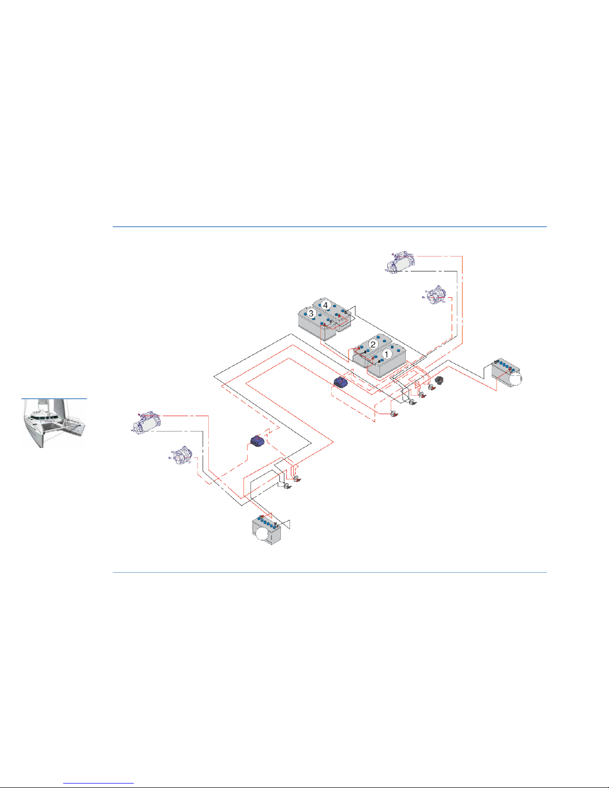
APPENDIX - BATTERY DIAGRAM
66
ELECTRICITY
LAGOON 44O
PORT
STBD
STBD BATTERY
SWITCH
STBD BATTERY
+ ENGINE SWITCH
BATTERY
COUPLING SWITCH
PORT BATTERY
SWITCH
BATTERY + SERVICE SWITCH
PORT BATTERY + ENGINE SWITCH
Page 69
67
ELECTRICITY
6
LAGOON 44O
Page 70

Page 71

69
WATER TANKS . . . . . . . . . . . . . . . . . . . . . . . . . . 71
FRESH WATER SYSTEM
. . . . . . . . . . . . . 71
GAS SYSTEM
. . . . . . . . . . . . . . . . . . . . . . . . . . . . 71
WATER DRAINAGE SYSTEM . . . . . . . 73
SANITARY EQUIPMENT
. . . . . . . . . . . . . . 75
Plumbing
7
Page 72
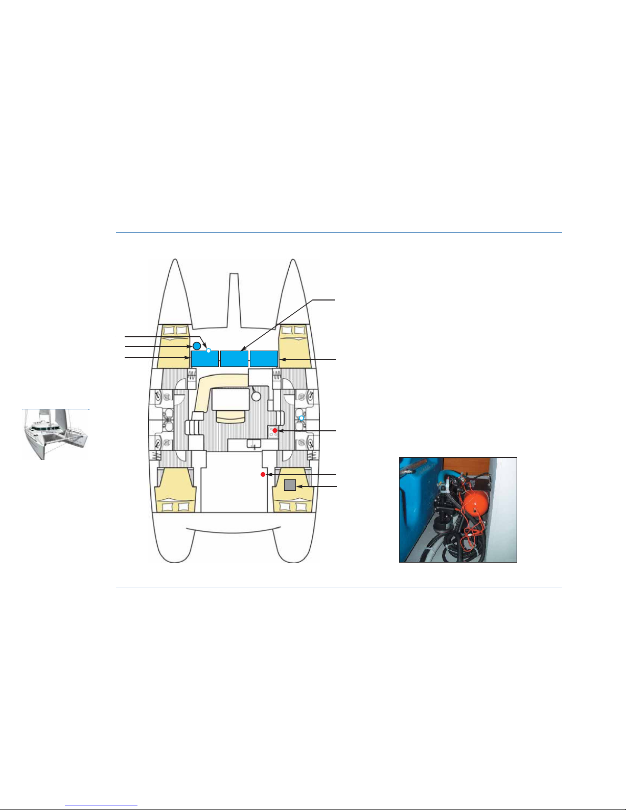
FRESH WATER AND GAS
70
PLUMBING
LAGOON 44O
3
7
5
6
1
8
4
1 - Deck filler.
2 - Water pump + expansion chamber.
3 - Forward port tank.
4 - Forward central tank.
5 - Forward starboard tank.
6 - Gas valve.
7 - Regulators in gas compartment.
8 - Water heater.
Locations are the same for the other layout version.
WATER PUMP +
EXPANSION CHAMBER
2
Page 73
Water tanks
z
FILLING
In order to prevent any handling mistakes, never fill the water and fuel
tanks at the same time.
During filling, avoid handling contaminants near the fillers.
Open and close the filler caps with the suitable key.
Check the filler cap seals for condition during filling.
The tanks are fitted with overflow outlets and vents.
Never insert the water filling hose deep down into the system in order
to prevent any over-pressure in the systems.
z
MAINTENANCE
Inspection points are provided on tanks and from which it is possible
to clean the inside.
NB: The capacity of the fresh water tank or tanks indicated on the
SPECIFICATIONS page may not be completely useable depending on
the trim and load of the boat.
. Fresh water system
The water pump is switched on at the electrical panel.
The three tanks are linked through gravity. The overall level can be
read on mark n°1 on the electrical panel gauge.
Gas system
Refer to the SAFETY chapter.
Refer to the "FRESH WATER AND GAS" diagram.
When changing the gas bottle, refit the cap in place on the regulator
threaded section (to avoid corrosion).
PLUMBING
71
PLUMBING
7
LAGOON 44O
RECOMMENDATION
- Check the quality of the water when filling. Check
whether or not it is drinking water.
- The tanks can be sterilized using a Clonazione
tablet (available from chemists).
- In the case of long periods of inactivity purify tanks
and piping using the appropriate treatment.
RECOMMENDATION
Shut off the gas safety valve and the regulator valve
when the stove is not in use.
RECOMMENDATION
- Never operate the water system equipment when
the valves are closed or the tank is empty (the
electrical equipment may be damaged).
- Check the water filter for condition (refer to
manufacturer's instructions).
Page 74
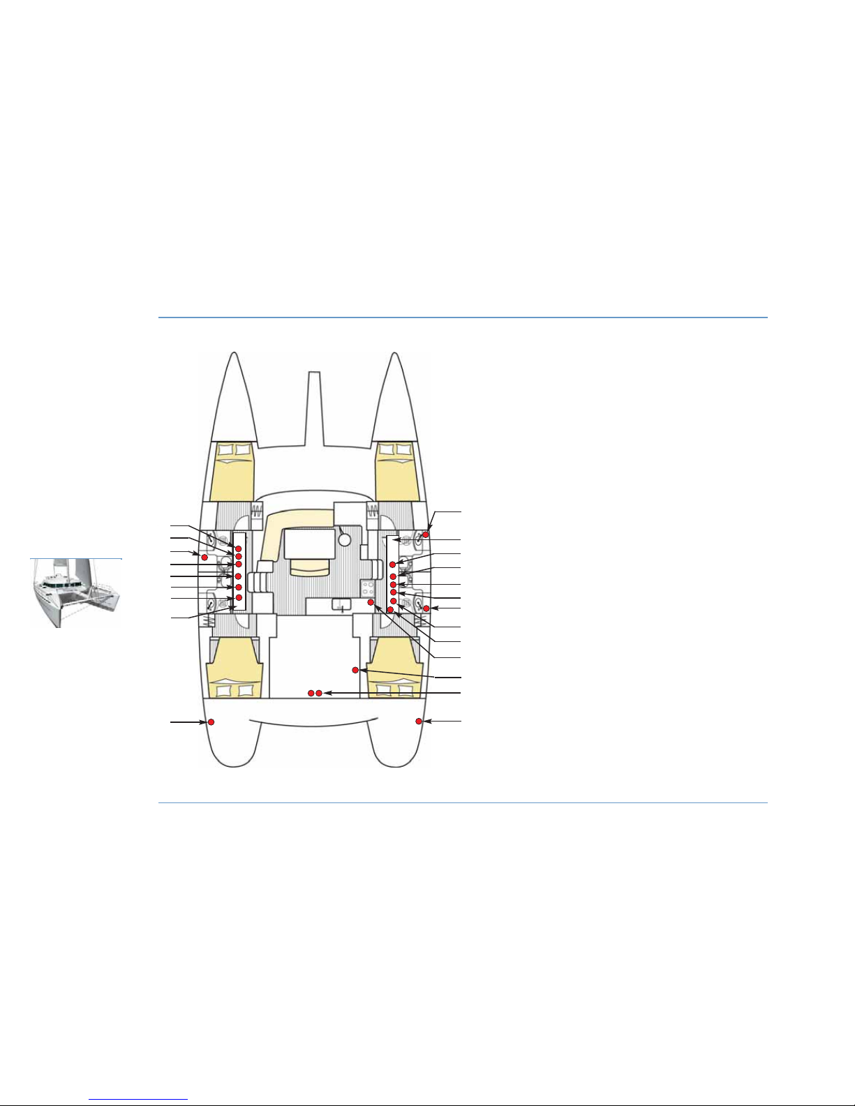
WASTE WATER SYSTEM
72
PLUMBING
LAGOON 44O
11
8
21
20
13
4
2
6
8
5
9
16
1 - Drain valve for forward port
watertight compartment.
2 - Drain pump for port shower.
3 - Forward port toilet drain.
4 - Strainer for port electric bilge
pump.
5 - Port electric bilge pump.
6 - Drain valve for port aft
watertight compartment.
7 - Port bilge pump with
automatic start + filter.
8 - Sump drain.
9 - Drain for port electric bilge
pump.
10 - Forward starboard toilet
drain.
11 - Drain valve for forward
starboard watertight
compartment.
12 - Strainer for starboard
electric bilge pump.
13 - Drain pump for starboard
shower.
14 - Starboard aft toilet drain.
15 - Starboard electric bilge
pump.
16 - Starboard bilge pump with
automatic start + filter.
17 - Drain valve for starboard aft
watertight compartment.
18 - Sink drain.
19 - Starboard aft cockpit drain.
20 - Manual bilge pump.
21 - Drain for starboard electric
bilge pump.
Locations are the same for the other layout version.
10
3
1
12
17
18
19
15
7
14
Page 75
Water system drainage
A main sump well is located under the floor of each hull.
It is drained by:
- A manual bilge pump in cockpit.
- A manually activated electric bilge pump (electrical panel and
steering station).
- An automatically activated submersible pump located in the well.
The fore compartments and the engine bilges are watertight. A hose
equipped with a valve enables water that enters accidentally to run
into the sump. These valves are located under the floor in fore and aft
cabins, near the sump.
Under normal conditions these remain closed.
Waste water drainage off the sink and the toilets is ensured by thruhull fittings with quarter turn valves (valve closed when the handle is
perpendicular to the pipe, valve open when the handle is in line with
the pipe).
z
MAINTENANCE
- Regularly check the valves and thru-hull fittings for proper operation
and water-tightness.
- Turn off the valves when the water system is not in use.
- Visually check water pump flow.
- Check the clamps and flexible hose connections for tightness, check
condition of the seals.
- Regularly make sure that the sump and bilge are perfectly clean.
PLUMBING
73
PLUMBING
7
LAGOON 44O
RECOMMENDATION
Immediately switch off the electric system if a pump
starts running when all the water supplies are
turned off.
- Check the system and neutralize the problem.
WARNING
The bilge pump system is not designed to provide
buoyancy for the boat in the event of damage.
The bilge pump system is designed to drain water
from sea spray or leaks but absolutely not to drain
water entering through a hole in the hull as a result
of damage.
Page 76
74
PLUMBING
LAGOON 44O
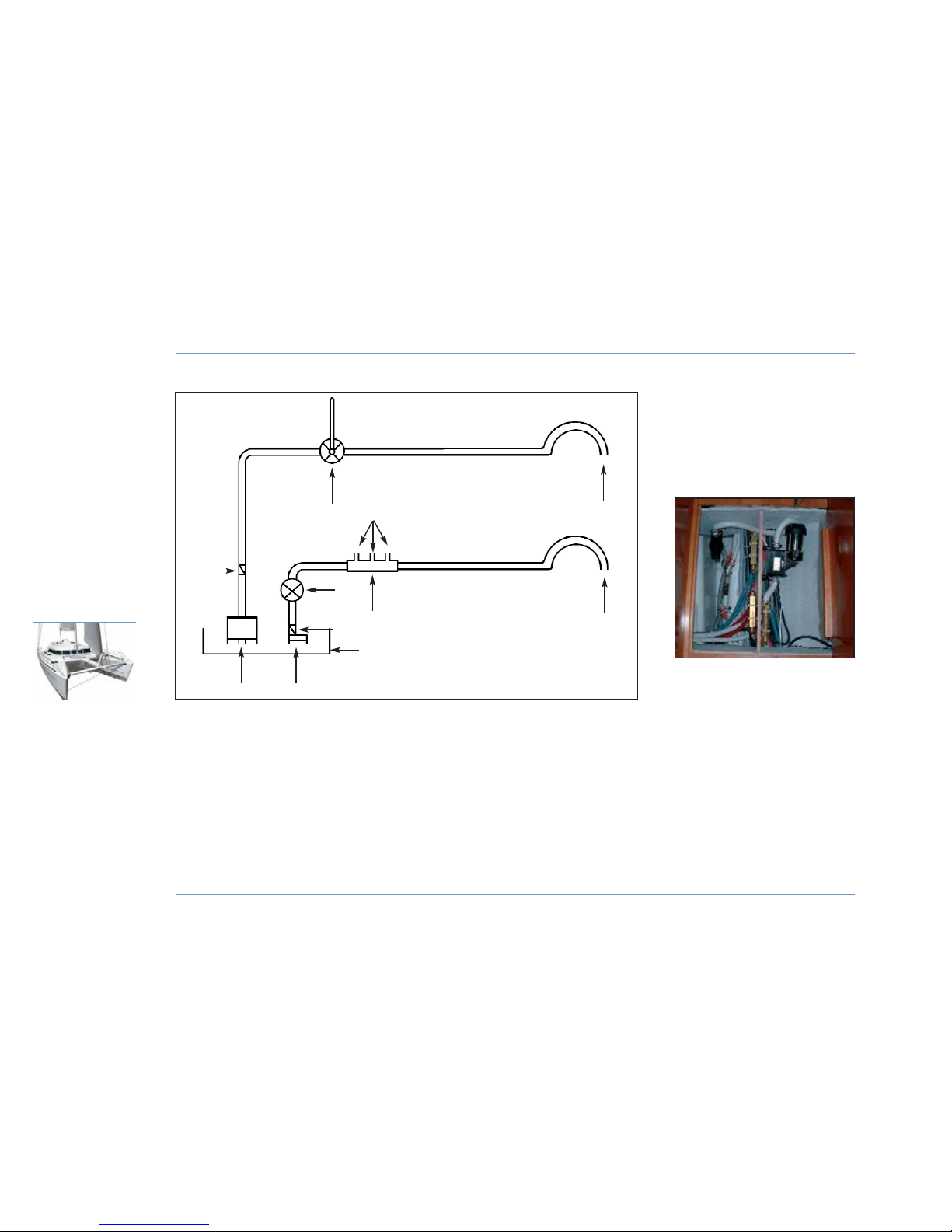
MAIN WATER DRAINAGE SYSTEM DIAGRAM
1 - Automatically activated submersible bilge pump.
2 - Strainer.
3 - Anti-return valve.
4 - Manually activated electric bilge pump (control on the
electrical panel).
5 - Distribution/recovery manifold for waste water.
6 - Waste water drainage from bathroom.
7 - Manual bilge pump in cockpit.
8 -Sump drain.
9 - Drainage outlet.
1
2
5
9
9
7
3
3
8
4
6
SUMP WELL
Page 77
Sanitary equipment
z
USE OF BASINS AND SHOWERS
Waste water from the shower room is evacuated to the sump by an
automatic start pump (located under the trough).
In the event of a breakdown in the automatic system, use the switch
to action the pump manually (located next to the pump).
Clean filters and trays regularly.
z
USE OF MARINE TOILETS
Before you use the heads, check that the water intake and draining
valves are open.
To empty the bowl:
- Set the control lever of the pump slantwise (FLUSH).
- Activate the pump.
To dry the bowl:
- Set the lever to vertical (DRY).
- Activate the pump.
ELECTRIC TOILETS (OPTIONAL EXTRA)
Ensure that the fuel valves are open.
The electric toilets are activated by the switch on the electrical panel.
Concerning use and maintenance of electric toilets refer to their
instructions.
In order to avoid clogging the heads, use absorbent paper only.
Rinse the heads regularly with fresh water.
Close the valves after each use (particularly when the boat is left
unattended).
PLUMBING
75
PLUMBING
7
LAGOON 44O
RECOMMENDATION
When alongside, use the sanitary facilities of the
port authorities (if available).
The waste holding tank must be used in marinas or
countries where the discharge of waste waters is
prohibited.
Page 78
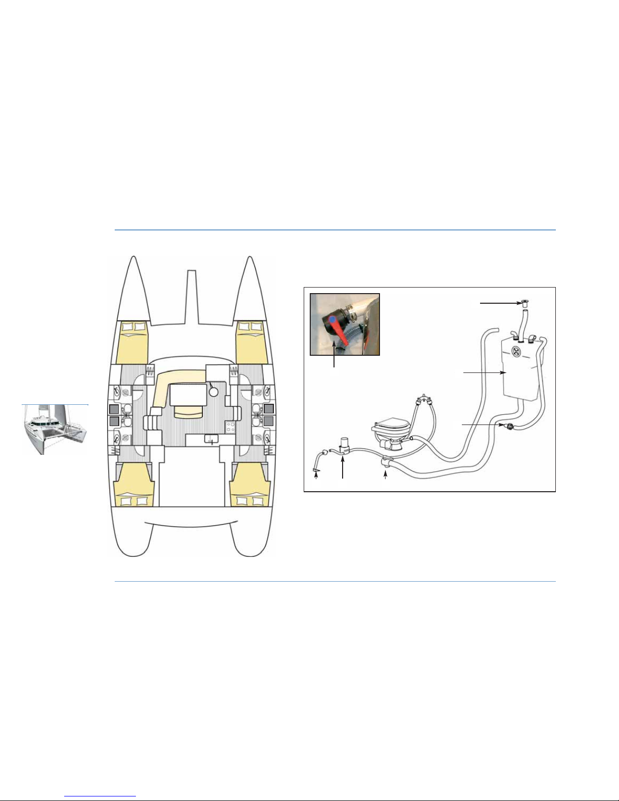
WASTE HOLDING TANKS
76
PLUMBING
LAGOON 44O
1
2
3
5 64
1 - Waste holding tank.
2 - Deck pump-out fitting.
3 - Vent hole.
4 - Sea water intake strainer.
5 - Electric pump.
6 - Drainage valve on hull.
WASTE WATER TANK SYSTEM
(PRESENT WITH ELECTRIC TOILET OPTION)
6
Page 79
The port aft toilets are fitted with a soil water tank. The other toilets
can have them fitted as an optional extra.
Before use ensure that the drain valve on the bowl is closed in order
to avoid any inadvertent discharge (valve is closed when the valve
handle is perpendicular with the pipe).
To empty the tank:
- In an authorized area, open the drainage valve.
- In marinas equipped with an organic waste suction system, insert
the aspiration hose into the tank through the deck pump-out fitting,
then start the suction.
The filler caps are opened and closed with an appropriate key.
When the tank has been emptied, check the cap seal for condition
then close the filler.
To rinse out the system, fill the tank with fresh or sea water, then
empty.
Only use domestic cleaning products.
The tanks must be empty when the boat is moored in negative
temperatures.
PLUMBING
77
PLUMBING
7
LAGOON 44O
RECOMMENDATION
For the protection of the environment, do not
discharge the contents of the waste holding tanks
near the shore.
RECOMMENDATION
Use the pump system at ports or marinas to empty
the waste holding tanks.
WARNING
Find out about current law in your country or marina
relative to discharging waste water into the sea.
Page 80

Page 81

79
FUEL TANKS . . . . . . . . . . . . . . . . . . . . . . . . . . . . . 81
FUEL FILTER
. . . . . . . . . . . . . . . . . . . . . . . . . . . . 83
ENGINES . . . . . . . . . . . . . . . . . . . . . . . . . . . . . . . . . 85
INSTRUMENT PANEL. . . . . . . . . . . . . . . . . 87
PROPELLERS AND ANODES . . . . . . 87
Motorization
8
Page 82
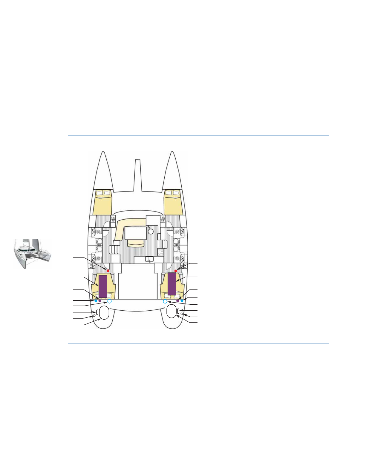
IMPLANTATION MOTORIZATION
80
MOTORIZATION
LAGOON 44O
7
6
7
8
8
1
2
1 - Fuel selector valve (push/pull).
2 - Fuel tanks.
3 - Fuel filter.
4 - Sea water filter.
5 - Expansion tank.
6 - Exhaust hose.
7 - Fuel fillers for tanks.
8 - Engine.
4
3
5
1
2
4
3
5
6
Page 83
Fuel tanks
The boat is fitted with two tanks (one in each hull).
They are both filled independently.
They both have a fuel gauge on the engine panel.
z
FILLING
Take the general precautions stated in the PLUMBING chapter relative
to filling the water tanks.
Fill the tanks using the two fuel fillers.
In order to protect the deck from possible fuel splash, wet the area
around the filler with sea water before you remove the filler cap.
In case of splashes, rinse the deck thoroughly (after refitting the filler
cap).
z
MAINTENANCE
- Regularly check the condition of the O-ring of the filler (in order to
prevent water entering the tanks).
- Do not shut the fuel valves after each use (except in the event of
prolonged absence).
- Keep the fuel tank as full as possible (to avoid condensation).
- Every 5 years clean the tank to remove any sludge deposits.
- Every year check the condition of the fuel system (hose, valves, etc.).
The capacity of the fuel tanks indicated on the SPECIFICATIONS page
may not be completely useable, depending to the trim and load of the
boat.
Always keep 20% of fuel as a reserve.
MOTORIZATION
81
MOTORIZATION
8
LAGOON 44O
DANGER
Stop the engine and do not smoke while filling fuel
tanks.
RECOMMENDATION
Have a professional carry out any work on damaged
parts of the fuel system.
Page 84
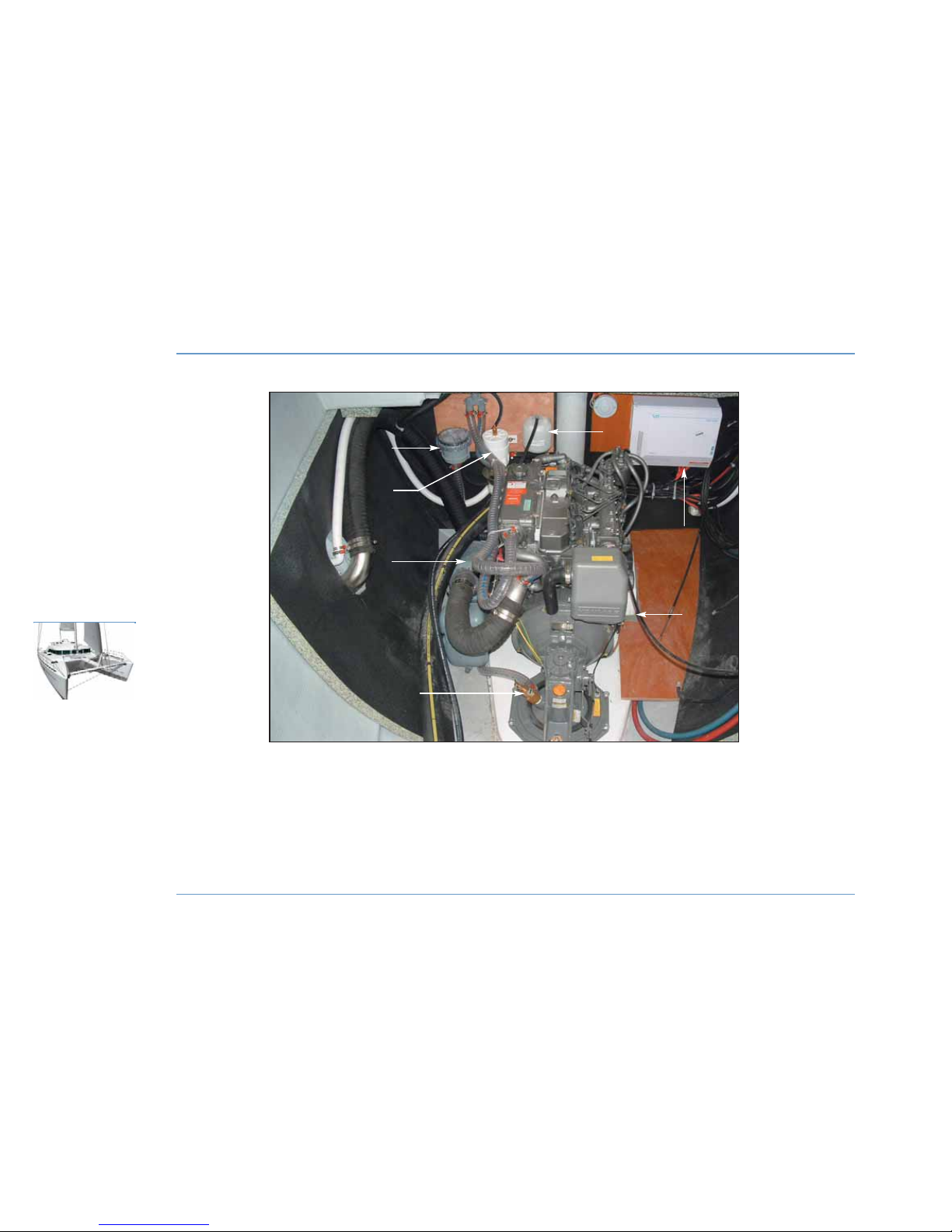
ENGINE INSTALLATION (PORT COMPARTMENT)
82
MOTORIZATION
LAGOON 44O
3
4
7
5
1
2
1 - Seawater filter.
2 - Fuel filter.
3 - Exhaust hose.
4 - Sea water engine intake valve.
5 - Expansion tank.
6 - Battery charger.
7 - Engine.
6
Page 85
Fuel filters
Problems with the engine may have various causes, one of which is
dirty fuel.
The injection pump may break down if there is water in the system.
Water in the fuel is a result either of condensation caused by an
insufficiently filled tank or by a filler-cap either not being closed
properly or with a damaged seal.
In order to prevent any water infiltration, the fuel runs through two
filters.
- The first filter is on the pipe that joins the tank to the engine, it has
the functions of a water decanter and pre-filter.
- A second filter is an integral part of the engine its role is to filter fuel
very finely. For information about maintenance and replacement,
please refer to the engine manual.
Drain by undoing the knurled screw at the base of the decantation
bowl (but not removing it).
Allow to flow into a box till the fuel looks clean.
Carry out this operation several times a year.
Change the pre-filter at least once a year (for access, remove the
bowl).
MOTORIZATION
83
MOTORIZATION
8
LAGOON 44O
Page 86
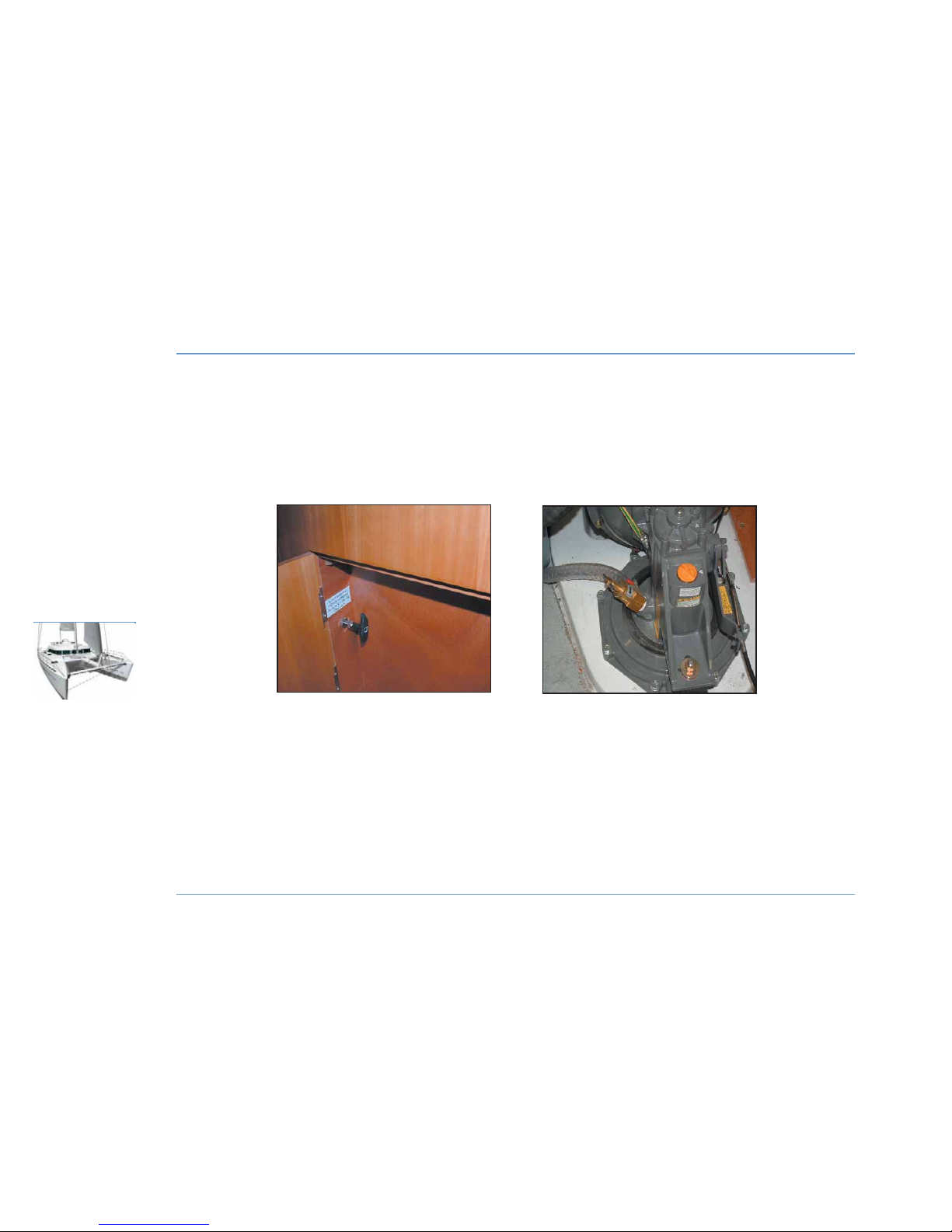
FUEL VALVE / ENGINE WATER VALVE
84
MOTORIZATION
LAGOON 44O
FUEL VALVES
ENGINE WATER INLET
Page 87
Engines
z
ACCESS TO ENGINES
Access to the engines is through the companionway hatches.
z
ENGINE WATER SUCTION INLETS
The water inlet valves are essential for the operation of the engine.
These valves must be open before the engine is started (risk of rapid
deterioration of the exhaust pipe and of major damage to the engine).
- Keep the strainer under the hull as clean as possible.
- Brush the strainer when the boat is hauled.
- Do not cover the strainer with antifouling paint.
RECOMMENDATION: Get into the habit of checking immediately after
starting the engine that water is expelled with the exhaust gases.
If no water is expelled:
- Stop the engine immediately.
- Check that the valve is open.
Close the water inlet valve if the boat is left unattended for a
prolonged period.
Inspect and clean the water filter regularly.
MOTORIZATION
85
MOTORIZATION
8
LAGOON 44O
RECOMMENDATION
Read carefully the instructions provided with your
boat.
RECOMMENDATION
Stop the engine before opening the hatches.
Should you need to access an engine while it is
running:
- Stay away from belts and mobile parts.
- Be careful to avoid catching clothing, long hair or
rings in the engine.
- Wear appropriate clothes (gloves, hat, etc.).
WARNING
Never run the engine when the boat is out of the
water.
Page 88
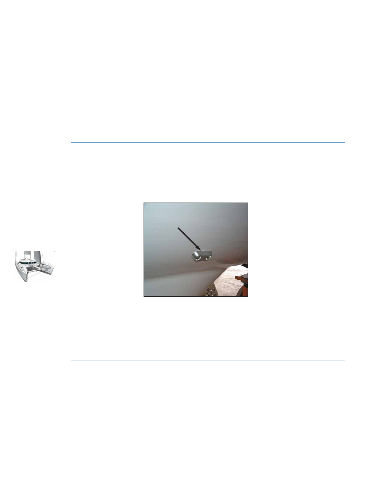
ANODES
86
MOTORIZATION
LAGOON 44O
ANODE
(On hull, under water line)
Page 89
z
FUEL
Do not wait until the fuel is nearly completely used up before filling up
(the system may stop due to lack of fuel).
Ensure you have enough fuel before sailing.
z
MAINTENANCE
Refer to the manufacturer's manual provided with your boat.
Be careful to avoid any spillage of fuel or oil.
Check the color of exhaust gases. In the case of excessive white or
black smoke, consult an engine specialist.
Instrument panel
The instrument panel contains all the checking functions of the
engine and it does not require any special precautions (refer to the
engine manual).
Propellers and anodes
The propellers supplied as a standard with your boat are the result of
tests carried out jointly with the engine manufacturer.
Remove the foldaway propellers (optional extra) at the end of each
season, dismantle them and clean them carefully.
Grease the thrust bearing surfaces and teeth.
Check that the propeller blades move easily.
If necessary, install new anodes (on hulls and base plates).
Replace anodes before they are 50% corroded.
MOTORIZATION
87
MOTORIZATION
8
LAGOON 44O
RECOMMENDATION
Do not change the propellers without a specialist's
advice.
RECOMMENDATION
Ensure that the base plate anodes have good metal
contact with the transmissions.
Never paint the anodes.
Assemble the propellers before re-launching the
boat.
Page 90

Page 91

89
STANDING RIGGING . . . . . . . . . . . . . . . . . . 91
RUNNING RIGGING
. . . . . . . . . . . . . . . . . . . 93
WINCHES
. . . . . . . . . . . . . . . . . . . . . . . . . . . . . . . . . 93
SETTING THE SAILS . . . . . . . . . . . . . . . . . . 95
SAILS . . . . . . . . . . . . . . . . . . . . . . . . . . . . . . . . . . . . . . 97
Rigging
& sails
9
Page 92
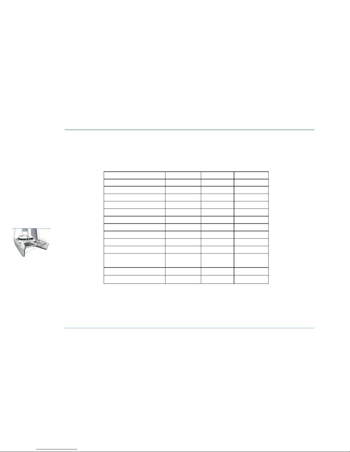
RUNNING RIGGING TABLE
90
RIGGING
& SAILS
LAGOON 44O
RRooppee iiddeennttiiffiiccaattiioonn lleennggtthh ((mm)) ddiiaammeetteerr ((mmmm)) ttyyppee
Reef 1 27 12 polyester
Reef 2 35 12 polyester
Reef 3 31 12 polyester
Main halyard 67 14 Dynema core
Spinnaker halyard (optional) 48 14 polyester
Spinnaker sheet (optional) 2 x 29 14 polyester
Genoa halyard 44 14 Dynema core
Boom topping lift 42 12 polyester
Genoa sheet 2 x 19 14 polyester
Mainsail sheet 50 14 polyester
Traveler control line 1 x 15 to port 10 polyester
1 x 16 to starboard
Genoa furler 33 10 polyester
Lazy-jack NC 6 polyester
Page 93

Standing rigging
z
ADJUSTMENTS
Your mast will have been pre-set both by the boatyard and by the
mast manufacturer during the first mast stepping.
However, after a few sea trips, the mast should be reset once the
cables have "given" to their full length.
Proceed as follows:
- Slacken the lower shrouds.
- Tighten the topping lift or use the mainsail halyard in its place.
- Loosen the lazy-jacks.
- Take up the upper and lower diamonds, evenly in order to obtain a
straight profile. The mast should now curve evenly towards aft.
- The forestay is pre-adjusted to have an angle of 2.6° to aft.
- Tension the backstays by tightening the turnbuckles with a wrench
and a 30 cm pipe (check that the mast head is centered).
- Take the tension back up in the lower shrouds by turning the
turnbuckles by hand.
- Take the lazy-jacks back up.
- The mast should remain curved towards aft.
Under sail with a 20 knot apparent cross wind, it is normal for the
leeward rigging to be slightly slack; if necessary, thread a shock cord
between the backstay and the lower shroud leeward to stop any
flapping.
z
MAINTENANCE
Before each trip, carefully inspect the mast from top to bottom.
Periodically check the tension of the rigging and the lock nuts or pins
for tightness (you should check them for the first time after a few days
sailing in all types of weather).
Secure and lubricate the turnbuckles with tallow, graphite grease or
other (never use silicone).
Check the tightness of the turnbuckles.
Inspect the turnbuckles for possible wear (due to chain-plate chafe if
the rigging is slack).
Change any shroud or stay with severed wires or kinks.
Regularly check the chain-plates for wear.
RECOMMENDATION: Your LAGOON dealer can carry out all
maintenance operations.
RIGGING & SAILS
91
RIGGING
& SAILS
9
LAGOON 44O
DANGER
To hoist a crew member up to the top of the mast,
make a bowline with the halyard directly on the
bosun's chair ring (never use the halyard shackle or
snap shackle).
Do not hoist a crew member when sailing in heavy
weather.
Page 94
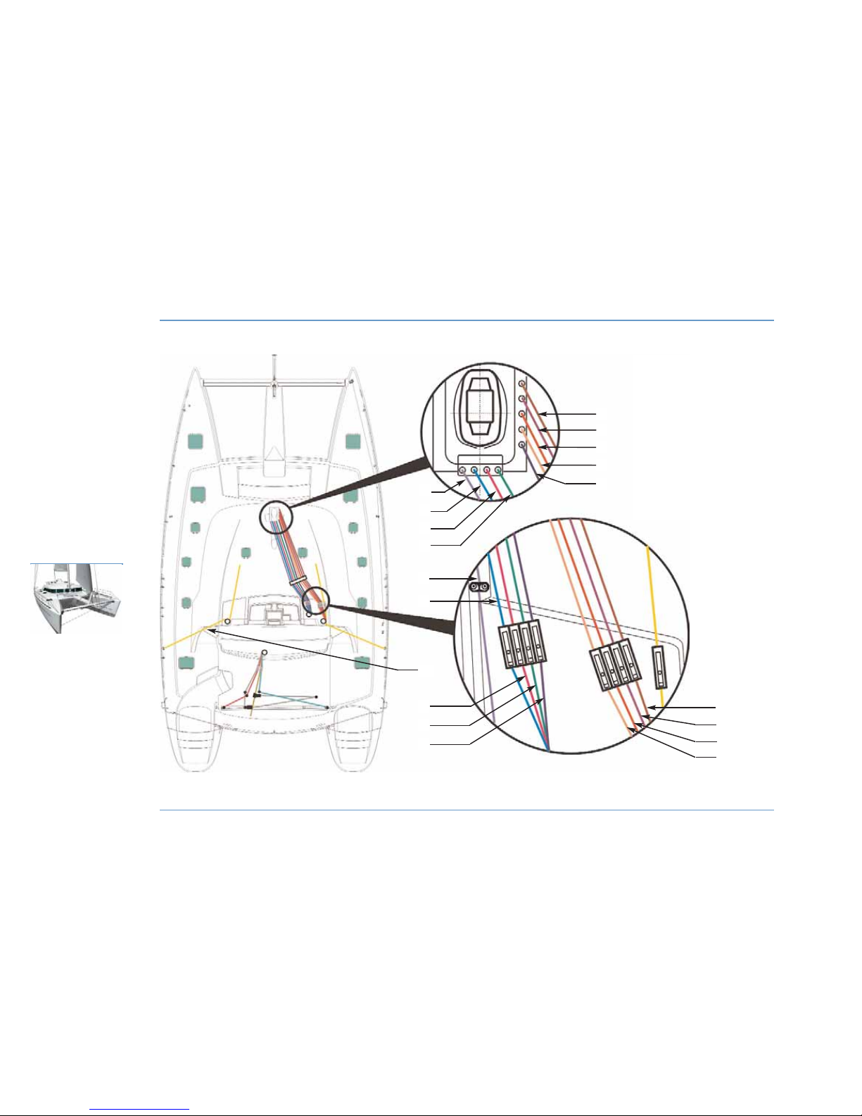
RUNNING RIGGING
92
RIGGING
& SAILS
LAGOON 44O
1
2
6
5
7
8
1 - Mainsail.
2 - Reef 1.
3 - Reef 2.
4 - Reef 3.
5 - Boom topping.
6 - Genoa halyard.
7 - Spinnaker halyard.
8 - Head downhaul for mainsail.
9 - Main halyard.
3
1
2
4
4
8
7
6
5
3
10
9
5
Page 95

Running rigging
Lubricate the sheaves with silicone. Replace any distorted or dented
sheaves. Inspect the sheave pins at the top of the mast once a year.
Regularly check the jam cleat jaws for condition.
Inspect the halyards for wear and condition.
Regularly clean the blocks (excess grease, corrosion spots).
Lightly lubricate the block axles.
Avoid ill-timed gibing in order to reduce premature wear on the
sheets and attachment points.
Winches
Avoid line jamming during winch handling.
Do not leave lines loose on the winches - fasten them on cleats.
Adjust the winches on taking delivery of your boat (rinse them
regularly during the season).
The winches should rotate freely; they need an overhaul when slight
seizing is noticed.
z
MAINTENANCE
Carry out complete maintenance of the winches regularly, before and
during the sailing season.
- Disassemble the drums to clean them.
- Lubricate the drums with a film of white grease or Teflon to reduce
friction and prevent corrosion (this type of grease is clean, non toxic
and biodegradable).
RIGGING & SAILS
93
RIGGING
& SAILS
9
LAGOON 44O
WARNING
Refer to the manufacturer's instructions to remove
and refit the winches.
Incorrect re-assembly may result in accidents (e.g.
crank handle kick).
RECOMMENDATION
A winch drum is designed to have a minimum
number of turns necessary so that it does not slip
and that the stress is not passed on to the selftailing mechanism.
Make at least 3 or 4 turns on the winch.
Page 96
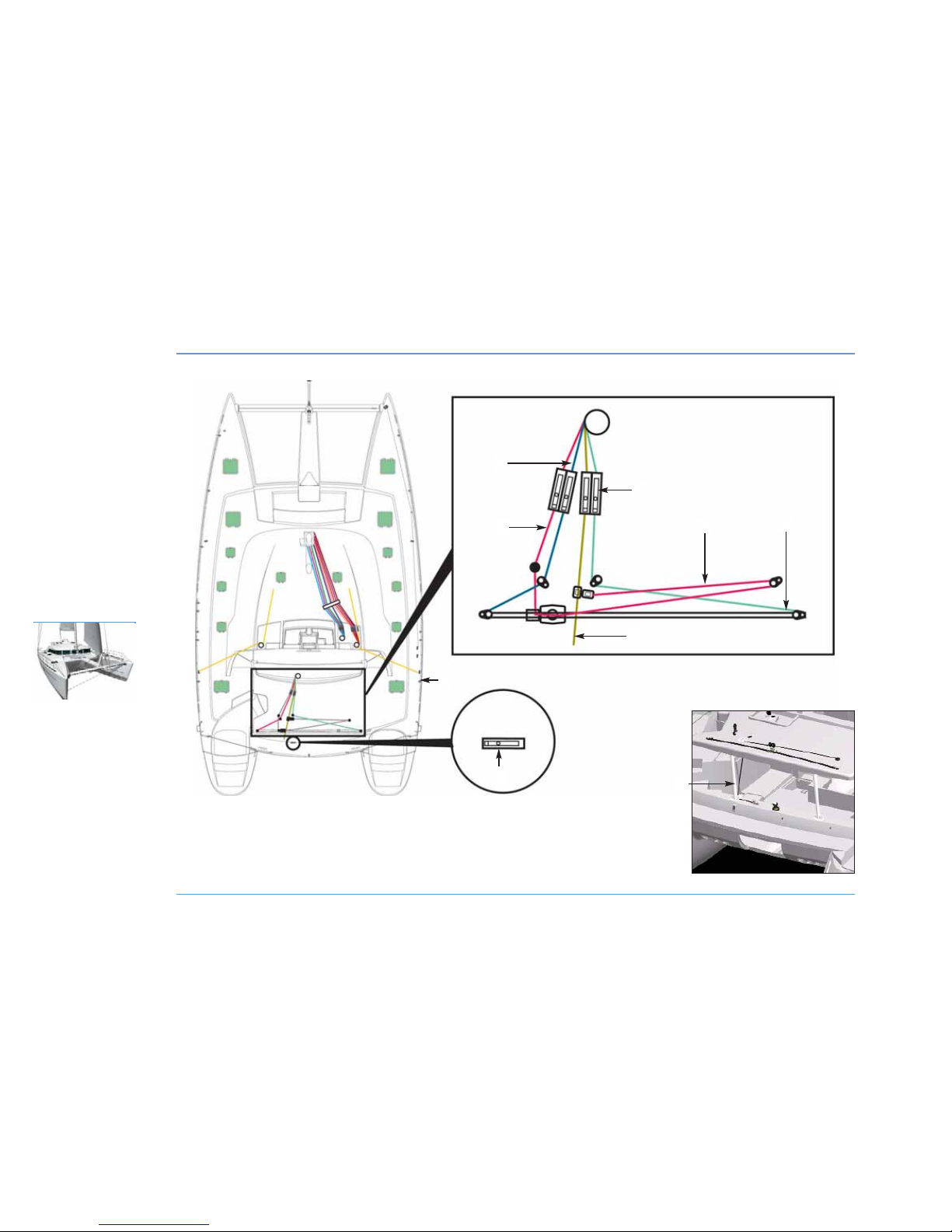
RUNNING RIGGING
94
RIGGING
& SAILS
LAGOON 44O
1
2
4
4
3
2
1 - Adjustable traveler for mainsail.
2 - Mainsail sheet.
3 - Genoa furler.
4 - Adjustable traveler for mainsail.
5 - Mainsail sheet (spare in cockpit).
6 - Passage of the mainsail sheet from the flying bridge.
7 - Padeye for Gennaker/Spinnaker block.
6
5
7
Page 97
Setting the sails
z
GENOA FURLER
Before getting under way,take advantage of a windless period to hoist
the Genoa.
Pre-roll the drum by hand to set the furling line on it.
Be careful of the way which the drum winds: The UV band should be
on the outside.
- Secure the head and halyard to the swivel. Secure the tack to the
drum and sheets to the clew.
- Insert the bolt line into the hole and hoist it, taking care not to tear
it.
- Tighten the halyard sufficiently but hoist it less taut than a sail on a
normal stay.
Hoist it until the horizontal creases disappear (adjust the tension of
the luff after a few miles at sea).
- Before you furl the Genoa, remove the ring that is used to guide the
luff tape. Keep the ring in a safe place and replace it before any
handling (lowering etc).
- Pull on the stopper from the cockpit to furl the Genoa.
Never force it in case it seizes when you furl or unfurl the head sails.
Check that no halyard is caught up in the furler and that the sail is not
too taut.
MAINTENANCE
- Rinse the drum and swivel regularly.
- Lubricate the bearings if recommended by the manufacturer.
- Unrig the sails if your boat is not to be used for a prolonged period.
z
MAINSAIL
To hoist the mainsail :
- Head into the wind.
- Slacken the mainsail sheet.
- Hoist the sail taking care that the battens do not catch up on the
lazy-jacks.
z
GENNAKER
Before getting under way,take advantage of a windless period to hoist
the Genoa.
- Fix the chain swivel to the gennaker head.
- Fix the take-up drum to the tack.
- Put the take-up drum on to the spar with a snap shackle.
- Fix the halyard to the head chain swivel.
- Hoist the gennaker.
Use the take-up drum stopper to furl or unfurl the gennaker.
SHEETS
- Fix the sheets to the gennaker clews.
- Thread the sheets around the outside of the stay and of the shrouds
and over the jack-lines.
- Fasten the sheet return blocks to the bolts.
RIGGING & SAILS
95
RIGGING
& SAILS
9
LAGOON 44O
WARNING
After chocking it, remove the gennaker halyard from
the starboard winch and lash it to the cleat.
Page 98
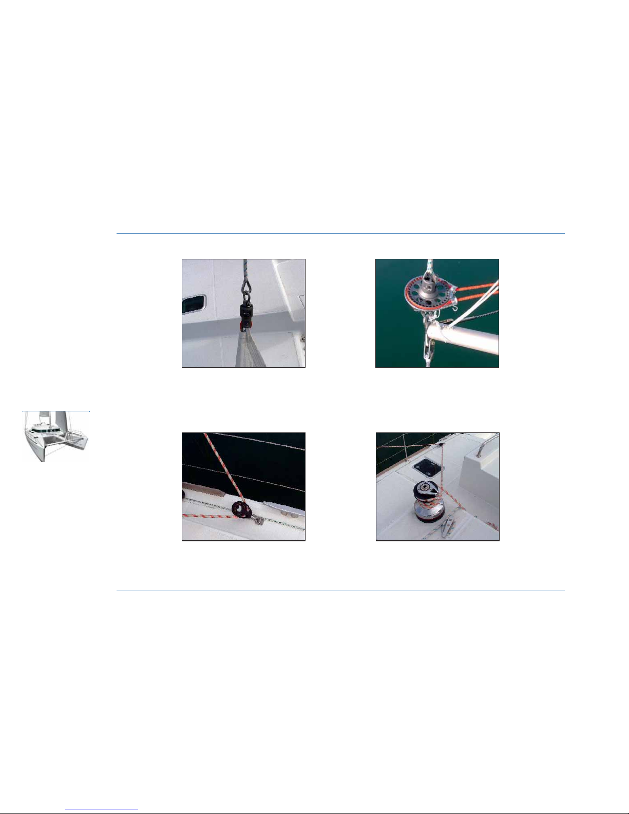
GENNAKER
96
RIGGING
& SAILS
LAGOON 44O
PASSAGE OF
GENNAKER SHEET
RETURN BLOCK FOR
GENNAKER SHEET
FIXING OF THE GENNAKER
HALYARD
ONTO THE HEAD
CHAIN SWIVEL
TAKE-UP DRUM
Page 99
- Lead the sheets back to the Genoa sheet winches.
Sails
How long a sail lasts mainly depends on how regularly it is
maintained.
Advice: At the end of the sailing season, and if possible before winter,
take your sails to a specialist for proper maintenance and repairs.
When the boat is under sail trim the sails properly and in accordance
with any stresses in order to reduce harmful strains on the fabric.
Prevent tears and wear: protect against chafing from accessories with
rough surfaces (protection for spreaders, stanchions etc.).
Between sea-trips, slacken the halyard (for the sails on furler) and the
foot of the mainsail.
Ensure you have a sail maker's kit and a manual so that you may
carry out emergency repairs until you can seek the assistance of a
sail maker.
z
CLEANING AND MAINTENANCE
Rinse the sails with fresh water from time to time and dry without
delay in order to avoid the formation of mildew.
Do not dry the sails by hoisting and letting them flap (when the sails
flap the seams become worn and the sails may be torn by the
rigging).
To remove grease spots: Use trichloroethylene and rinse immediately
with water.
z
STORING/FOLDING
Avoid storing wet sails to prevent mildew from forming.
Accordion-fold the sail parallel to the foot, then roll it up to the
dimensions of the bag.
z
PROTECTION
UV rays are harmful to polyester and nylon.
If the sails remain on the mast, even for 24 hours, protect them with
a cover or a protective material placed on the leech and foot of the
furled sails.
Our network of agents offers accessories selected by the yard to meet
your needs.
RIGGING & SAILS
97
RIGGING
& SAILS
9
LAGOON 44O
WARNING
De-rig the gennaker when not in use (danger of
damage through UV rays and accidental unfurling).
Page 100

 Loading...