

Page 1
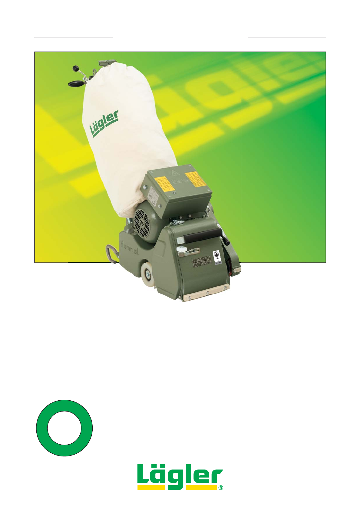
BELT SANDING MACHINE HUMMEL
S
t
a
u
b
-
d
u
s
t
-
p
o
u
s
s
i
è
r
e
-
p
o
l
v
o
-
®
-
b
u
a
t
u
d
S
-
Operation,
Maintenance, Safety
Translation of original operating instructions
-
t
s
<
1
mg/m³
o
l
v
p
o
u
s
s
i
è
r
e
-
p
o
for the belt sanding machine
®
HUMMEL
English / Englisch
00.100.20.002 01.12.2012
*00.100.20.002*
Page 2
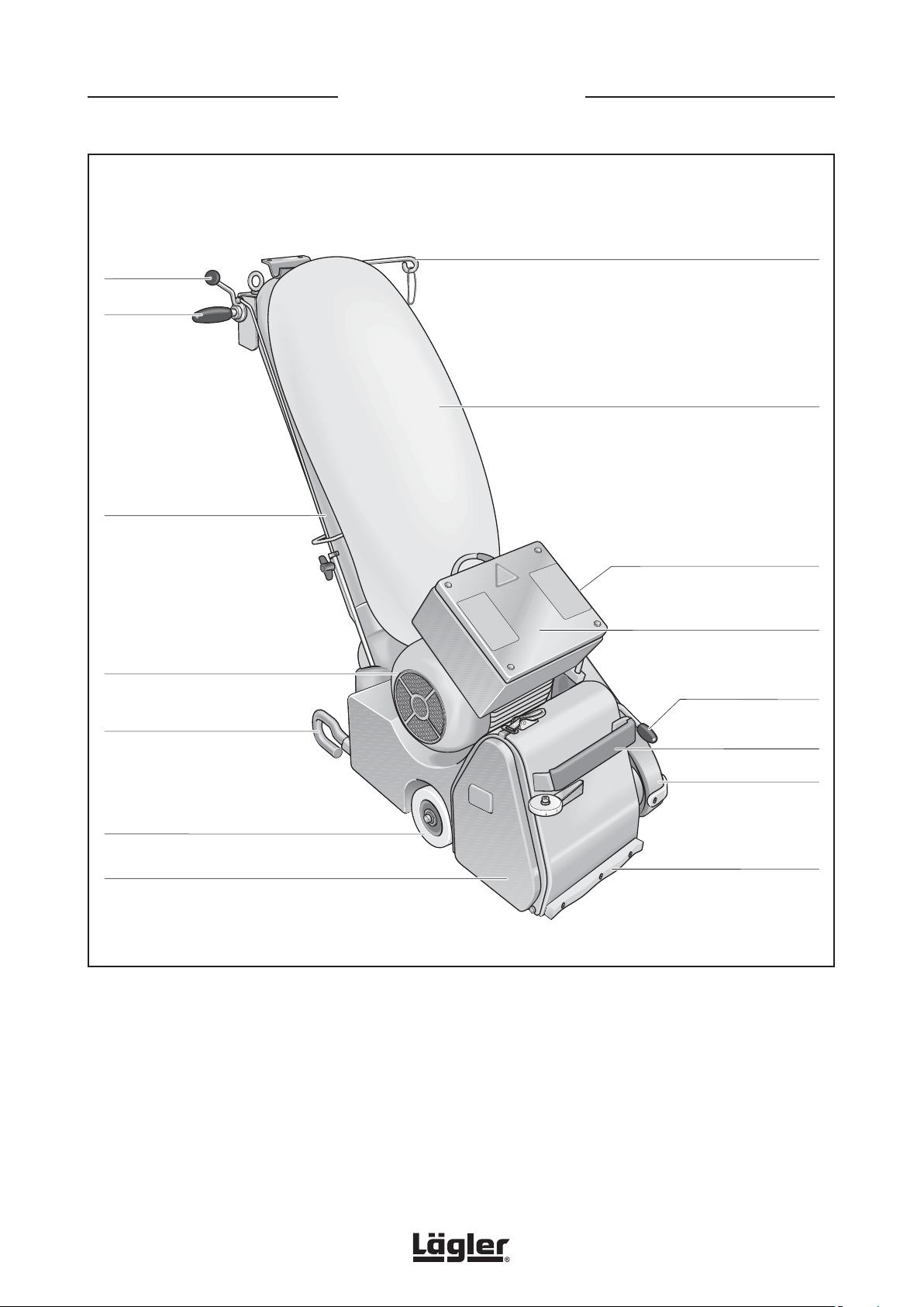
Lowering
lever
Handle
Guide tube
HUMMEL® - ASSEMBLIES
Cable support with
strain relief ring
Dust bag
Drive motor
Safety guard
Lateral wheel
Side cover
Fig. 1 Assemblies of the HUMMEL® belt sanding machine
ON/OFF switch
Switch box
Operating lever,
drive unit
Bracket
Belt guard
Bumper felt
HUMMEL® 01.12.2012
2
English / Englisch
Page 3

CONTENTS
1 Introduction .....................................................................................................................................................................4
1.1 Features of the machine ................................................................................................................................................4
1.2 Description of the machine ...........................................................................................................................................4
1.3 Intended use of the machine .........................................................................................................................................4
1.4 Safety devices.................................................................................................................................................................4
2 Hazard warnings and safety instructions ....................................................................................................................5
2.1 Hazard warnings .............................................................................................................................................................5
2.2 General safety instructions ...........................................................................................................................................8
3 Technical data ...............................................................................................................................................................10
4 Commissioning ..............................................................................................................................................................12
4.1 Preparing the machine for operation .........................................................................................................................12
4.2 Connecting the power cable .......................................................................................................................................15
4.3 Switching on the machine ...........................................................................................................................................16
4.4 Switching off the machine ...........................................................................................................................................18
5 Working with the HUMMEL® .......................................................................................................................................19
5.1 Application tips ............................................................................................................................................................. 19
5.2 Changing the sanding belt ...........................................................................................................................................20
5.3 Regulating the sanding drum pressure ......................................................................................................................22
5.4 Emptying the dust bag ..................................................................................................................................................23
6 Transport and storage ..................................................................................................................................................24
6.1 Dismantling the machine before transportation .......................................................................................................25
6.2 Assembly after transportation ....................................................................................................................................27
6.3 Storage ..........................................................................................................................................................................28
7 Maintenance work and replacement of wearing parts ............................................................................................29
7.1 Cleaning and care instructions ...................................................................................................................................30
7.2 Lubrication ....................................................................................................................................................................33
7.3 Checking and setting the sanding belt tracking ........................................................................................................33
7.4 Checking the machine setting .....................................................................................................................................36
7.5 Checking the dust pick-up ...........................................................................................................................................38
7.6 Replacement of sanding drum ....................................................................................................................................38
7.7 Replacement of tensioning roller ................................................................................................................................39
7.8 Replacement of rear wheel .........................................................................................................................................41
7.9 Replacement of lateral wheels ................................................................................................................................... 42
7.10 Replacement and tensioning of V-belts ..................................................................................................................... 42
8 Regular maintenance and testing in accordance with accident prevention regulations ....................................46
9 Causes of faults ............................................................................................................................................................48
10 Circuit diagrams ............................................................................................................................................................53
11 Spare parts .................................................................................................................................................................... 56
12 Service passport ...........................................................................................................................................................71
13 EU Declaration of conformity ...................................................................................................................................... 72
WARNING!
CAUTION!
ATTENTION! An undesired event can occur if the corresponding instructions are not followed!
HUMMEL® 01.12.2012
English / Englisch
Death, severe physical injury or significant property damage can occur if the
corresponding cautionary measures are not taken!
Moderate to light physical injury or property damage can occur if the corresponding
cautionary measures are not taken!
3
Page 4
1
INTRODUCTION
Introduction
You have purchased a high-quality product
from LÄGLER®. We wish you a great deal of
success with your HUMMEL®. All LÄGLER®
products are subjected to a thorough
inspection before leaving the factory.
Please read these operating instructions
completely before you begin working
with your HUMMEL®. These operating
instructions include important information
on occupational safety and will provide
you with answers to many questions so
that you can work with the machine safely
and without any problems. If you cannot
find a specific subject in these operating
instructions, please read the LÄGLER®
application technique guidelines “Sanding
of wooden floors” (http://www.laegler.com)
or contact our service department, your
retailer or your importer.
1.1 FEATURES OF THE MACHINE
Figure 1 (page 2) shows the most important assemblies which
make up the HUMMEL®. We recommend that you take some time
to become familiar with the machine.
1.2 DESCRIPTION OF THE MACHINE
The HUMMEL® belt sanding machine operates with a contact
sanding drum featuring a specially profiled rubber coating. The
belt tensioning fixture with integrated automatic belt guidance is
located vertically above the sanding drum. The work zone is covered
by the machine housing and detachable side cover. On the machine
housing, the electric motor is fixed in a motor bearing bracket. The
plug for connection to the mains is located at the switch box of the
motor. The motor switch with the switch positions START / WORKING
and TEST is located at the switch box. On the left under the belt
guard is the belt drive unit. The machine is moved by means of a
steering wheel at the back and two lateral wheels. Two handles are
attached to the guide tube, where the drum lowering lever is also
located and the cables and dust bag are attached.
WARNING!
RISK OF DEATH from electrical shock:
The machine may never be used for wet
processing operations of any kind!
1.3 INTENDED USE OF THE MACHINE
The HUMMEL® belt sanding machine is suitable for dry sanding
wooden and cork floors, plastic skating rinks and tartan running tracks.
A specially equipped version of the machine can be used to sand
sheet metal surfaces.
Any application other than that described here is inadmissible
without the consent of the manufacturer!
1.4 SAFETY DEVICES
The following parts of the machine are safety devices and must
accordingly be kept in perfect working order:
Sealing felt = Dust shield
Side cover = Dust shield, sanding belt protection
Machine housing = Sanding belt protection
Belt guard = V-belt protection
HUMMEL® 01.12.2012
4
English / Englisch
Page 5
2
HAZARD WARNINGS AND SAFETY INSTRUCTIONS
Hazard warnings and safety instructions
2.1 HAZARD WARNINGS
WARNING!
WARNING!
RISK OF DEATH from suffocation and RISK OF INJURY:
• Never wrap the power cable around your neck or other
parts of the body!
RISK OF DEATH from electrical shock:
• The machine may never be used for wet processing
operations of any kind!
• Do not expose the machine to rain! Do not use the machine
in moist or wet environments!
• To protect yourself and the machine against faults in the mains
supply use a safety switch (for German mains supply Part
number in Section 11, Spare parts)!
Note the valid regulations and legal conditions in your
country!
• The machine must be switched off and the power plug must
be removed from the socket during all maintenance work and
work on the electrical equipment!
RISK OF DEATH, RISK OF INJURY, RISK OF
FIRE:
• Be certain to read the hazard warnings
and safety instructions before using the
machine!
• Instruct your co-workers and colleagues
accordingly! Otherwise, these persons
could be exposed to danger or injured!
ATTENTION!
• Keep these hazard warnings and safety
instructions in a safe place!
• Note the valid regulations and legal
conditions in your country!
• Avoid body contact with grounded parts, e.g. pipes, radiators,
ovens, refrigerators!
• The quality of the motor cable and the power cables must
match the quality of the original LÄGLER® cable!
• The power cables must be protected from mechanical and/
or electrical damages in the workplace!
• Do not carry or pull by the machine by the cable! Do not pull
on the cable to remove the plug from the socket! Protect the
cable against heat, oil and sharp edges!
HUMMEL® 01.12.2012
English / Englisch
5
Page 6

2
HAZARD WARNINGS AND SAFETY INSTRUCTIONS
WARNING!
RISK OF EXPLOSION due to sparks while sanding or a high dust
concentration in the air:
• Do not use the machine near
- sources of fires,
- flammable liquids or gases,
- potentially explosive areas!
• Do not smoke in a dusty environment, e.g. while sanding or
emptying the dust bag!
RISK OF FIRE from spontaneous combustion or from sparks while
sanding:
• There is a high risk of fire when sanding woods with a large
amount of resin, oiled or waxed floors or metal! Therefore,
the machine must always be cleaned carefully directly after
sanding! Be certain to note the warning notices of the paint,
oil and wax manufacturers!
• Cloths, pads, et cetera which have been immersed in oil or wax
can spontaneously combust! Be certain to note the warning
notices of the paint, oil and wax manufacturers!
• The dust bag must always be removed from the machine
after sanding and emptied into a non-combustible container
outdoors! Cover this container with a non-combustible
cover and be certain to store it and the dust bag outdoors
( Section 5.4, Emptying the dust bag)!
RISK OF FIRE from the overheating of the cables:
• Only the following motor cables and power cables may be
used:
- machines with motor for mains voltage 220 V or 230 V:
3 wires with wire cross-sections of at least 2.5 mm²
- machines with motor for mains voltage 400 V:
5 wires with wire cross-sections of at least 1.5 mm²
HUMMEL® 01.12.2012
6
English / Englisch
Page 7

2
HAZARD WARNINGS AND SAFETY INSTRUCTIONS
WARNING!
HEALTH RISK caused by dust:
• Make sure that the dust bag is properly fastened to the
machine!
• If the machine is operated correctly, the mandatory dust
emission values will not be exceeded! When emptying the
dust bag outdoors, a respiratory protective mask (at least
filter class P2) must be worn!
• A respiratory protective mask (at least filter class P2) must
be worn when conducting other work that creates dust, e.g.
cleaning of the machine!
CAUTION!
RISK OF INJURY and RISK OF PROPERTY DAMAGE from rotating
tools and parts of the machine:
• Before switching on the machine, make sure that all tools
and adjustment tools have been removed from the machine!
• The machine may not be started when tilted backward or
forward!
• The machine may not be started if the sanding drum is on the
floor!
• Do not reach into rotating tools or parts of the machine!
• Do not let children or other persons touch the machine or
cable and keep them out of the work area!
• Do not wear any long articles of clothing or jewellery! These
could be caught by moving parts!
RISK OF INJURY and RISK OF PROPERTY DAMAGE from unintentional starting of the machine:
• The power plug must be removed from the socket when the
machine is switched off!
• Make sure that ON/OFF switch is not set to ON when
connecting the machine to the mains supply!
HUMMEL® 01.12.2012
English / Englisch
7
Page 8

2
HAZARD WARNINGS AND SAFETY INSTRUCTIONS
CAUTION!
RISK OF INJURY and RISK OF PROPERTY DAMAGE from the rolling
away, tipping or falling of the machine:
• The machine must be secured against rolling away, tipping
or falling when not in use!
Always ensure that the machine is standing securely!
RISK OF INJURY and RISK OF PROPERTY DAMAGE from unsuitable
parts:
• Only use tools, accessories and spare parts from LÄGLER®
for the HUMMEL® ( Section 11, Spare parts)! There is no
guarantee for external parts or liability for damage caused
by them!
HEALTH RISK caused by noise:
• Use hearing protection when conducting work that produces
noise!
RISK OF PROPERTY DAMAGE:
• Do not store the unused machine on the sanding drum!
Otherwise the sanding media can cause scratches on the
ground or the sanding drum can be damaged!
• Improper transport will result in damage to the machine!
2.2 GENERAL SAFETY INSTRUCTIONS
• Provide good illumination in the workplace!
Well lit construction sites reduce the risk of injury and allow
you to better evaluate the quality of your work.
• Keep your work area clean!
Untidy work area create a risk of accidents.
• Use the proper machines!
Do not use low-performance machines or additional devices
for heavy jobs. Do not use the machine for purposes and work
that it is not intended for.
• Do not overload the machines!
It works better and more safely in the power range noted.
HUMMEL® 01.12.2012
8
English / Englisch
Page 9

2
HAZARD WARNINGS AND SAFETY INSTRUCTIONS
• Do not bend too far over the machines!
Avoid unnatural postures. Make sure that you stay in a stable
position and keep your balance at all times.
• Be attentive!
Pay attention to your work. Work carefully and do not use the
machines if you are not concentrating.
• Maintain your machines with care!
Keep your machines clean so that you can work better and
more safely. Follow the maintenance guidelines and the
instructions for replacing tools. Regularly inspect the cable
and have it replaced by a qualified electrician if it is damaged.
Inspect the extension cable regularly and replace it if it is
damaged. Keep the handles dry and free of oil and grease.
• Check your machines for damage!
Before using the machines, you must inspect the safety
devices or damaged parts carefully to ensure that they are
working perfectly and as intended. Check whether the moving
parts are working properly, that they are not sticking, that no
parts are broken, whether all parts are in perfect condition
and installed properly and whether all other conditions which
could influence the operation of the machine are in order.
Damaged safety devices and parts must be properly repaired
or replaced by an authorized service shop insofar as nothing
to the contrary is indicated in the operating instructions.
Damaged switches must be replaced by a qualified
electrician. Do not use the machine if it cannot be started or
switched off by using its switch.
• Store your machines safely!
Store your unused machines in a dry, closed location out of
the reach of children!
HUMMEL® 01.12.2012
English / Englisch
9
Page 10
Technical data
NOTE on noise emission:
The values indicated are emission values
and must not represent safe workplace
values as well.
Although a correlation exists between
emission levels and immission levels, it is
not always possible to determine whether
additional precautionary measures are
required.
Factors that can have an effect on the
immission level existing at the workplace
include the duration of the effects, the
characteristics of the work area and
other sources of noise, e.g. the number of
machines and processing operations in the
vicinity. The permissible workplace values
may also vary from country to country.
This information, however, is intended
to enable the user to better estimate the
dangers and risks.
3
TECHNICAL DATA
Manufacturer ....................................................... Eugen Lägler GmbH
Machine type .................................................... belt sanding machine
Serial number ................................................................see type plate
Year of manufacture......................................................see type plate
Motor type .......................................................single-phase AC motor
- Voltage ................................................................230 V | .......... 220 V
- Frequency ............................................... 50 Hz (CPS) | 60 Hz (CPS)
- Output .............................................................. 2.2 kW | ........2.9 kW
- Necessary fuse protection of mains supply .....16 A | ............20 A
- Starting capacitor .............................................60 µF | ........ 130 µF
- Running capacitor ............................................. 40 µF | .......... 40 µF
Motor type ........................................................ three-phase AC motor
- Voltage ........................................................................................ 400 V
- Frequency ........................................................................50 Hz (CPS)
- Output .......................................................................................4.0 kW
- Necessary fuse protection of mains supply .............................16 A
Insulation class ...................................................................................B
Protection class ............................................................................IP 54
Safety devices ......................................................no-voltage release,
temperature switch as overload
protection in the motor
NOTE:
The motor data indicated here refers to
machines used in Germany or USA. Exported
machines may have other data that can be
seen on the motor type plate.
Drum diameter .......................................................175.5 mm (~ 6 7/8“)
Drum width ................................................................200 mm (~ 7 7/8”)
Drum speed ................................................................ 2400 1/min (rpm)
Dimension of the sanding belt ...... 200 x 750 mm (~ 7 7/8” x 29 1/2”)
Overall length of the machine ................................... 1040 mm (~ 41“)
Overall width of the machine ......................................360 mm (~ 14“)
Overall height of the machine ............................. 1020 mm (~ 40 1/8“)
Weight of the machine housing ..................................41 kg (~ 90 lbs)
Weight of the motor .....................................................34 kg (~ 75 lbs)
Weight of the guide tube .................................................4 kg (~ 9 lbs)
Overall weight of the machine ..................................79 kg (~ 174 lbs)
Dust emissions at workplace .............. < 1 mg/m³ (~ 0.012 gr./cu.yd.)
(measured as per the testing requirements GS-HO-15 of
German statutory accident insurance DGUV)
Workplace-related noise emission values ...........................76 dB(A)
Measurement uncertainty constant of the
noise emission values ............................................................4 dB (A)
Vibration total value ahv ........................................................< 2.5 m/s²
(measured at the handle)
10
HUMMEL® 01.12.2012
English / Englisch
Page 11
3
TECHNICAL DATA
Intended applications
Sanding wooden and cork floors, plastic skating rings, with special
version also machining of sheet metal surfaces.
WARNING!
Basic equipment
Machine ready for operation, dust bag, MultiClip for dust bag fixture,
cable support, 10 m extension cable 3 x 2.5 mm² (or 5 x 1.5 mm² for
three-phase AC motor), O-ring as a strain relief device, operating
instructions with safety remarks, tool kit complete with closed mouth
wrench size 13/10 mm, open-mouth wrench size 17 mm, hexagonal
socket wrench size 4 mm, 5 mm and 6 mm, setting fixture, box wrench
and respiratory protection mask P3.
Optional equipment
Carrying handle, TransCart, pocket for ear plugs, safety switch for
fault current PRCD-S (for German mains supply), safety belt.
Wearing parts
Please check the condition of the wearing parts mentioned below
at regular intervals in order to be able to work safely and optimally
at all times.
Replace the following parts in case of wear and/or damage:
• Extension cable
• Motor cable
• Sealing felt
• MultiClip
• V-belts
• V-belt pulleys
• Belt tensioner
• Sanding drum
(after daily use, exchange every 1 - 2 years)
• Tensioning roller of the drive unit
(after daily use, exchange every 1 - 2 years)
• Guide rollers at the drive unit
• Guide roller at the machine housing
• Side cover
• Dust bag
• O-ring used as a strain relief
• Back wheel
• Lateral wheels
RISK OF DEATH from electrical shock:
The machine may never be used for wet
processing operations of any kind!
NOTE:
You will find the corresponding part numbers
for the optional equipment and wearing
parts in Section 11, Spare parts.
HUMMEL® 01.12.2012
English / Englisch
11
Page 12
Commissioning
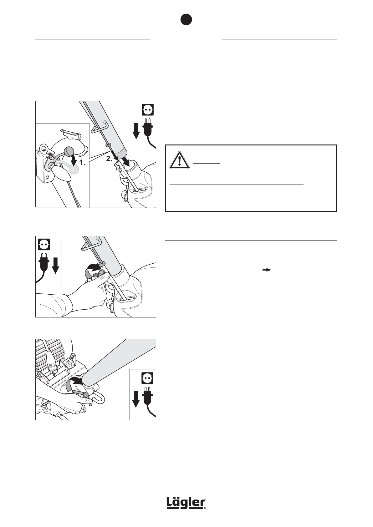
Fig. 2 When inserting the guide tube, make sure that
the upper rod of the lowering mechanism feeds
in correctly!
4
COMMISSIONING
This section describes the procedure for commissioning the
HUMMEL® on site. In order to exclude the possibility of damage and
malfunctions, it is essential to proceed in the sequence outlined
below.
CAUTION!
RISK OF INJURY and RISK OF PROPERTY DAMAGE:
Before working with the machine for the first time, operating
staff must be adequately instructed!
4.1 PREPARING THE MACHINE FOR OPERATION
Fig. 3 After inserting the guide tube, carefully tighten
the wing screw at the lower rod.
Fig. 4 After inserting the guide tube, carefully tighten
the wing nut at the machine housing.
1 Unpack the machine carefully. The bottom part of the supplied
transport crate makes a useful container for storage or
transportation of the machine ( Section 6, Transport and
storage). Please ensure that the packaging materials are
responsibly disposed of.
2 Press the lowering lever at the handle downwards (Fig. 2, 1.).
3 Insert the guide tube into the opening in the machine housing
and at the same time insert the upper rod into the lower rod
(Fig. 2, 2).
4 Carefully tighten the wing screw at the lower rod (Fig. 3) and
the wing nut at the machine housing (Fig. 4).
12
HUMMEL® 01.12.2012
English / Englisch
Page 13
4
COMMISSIONING
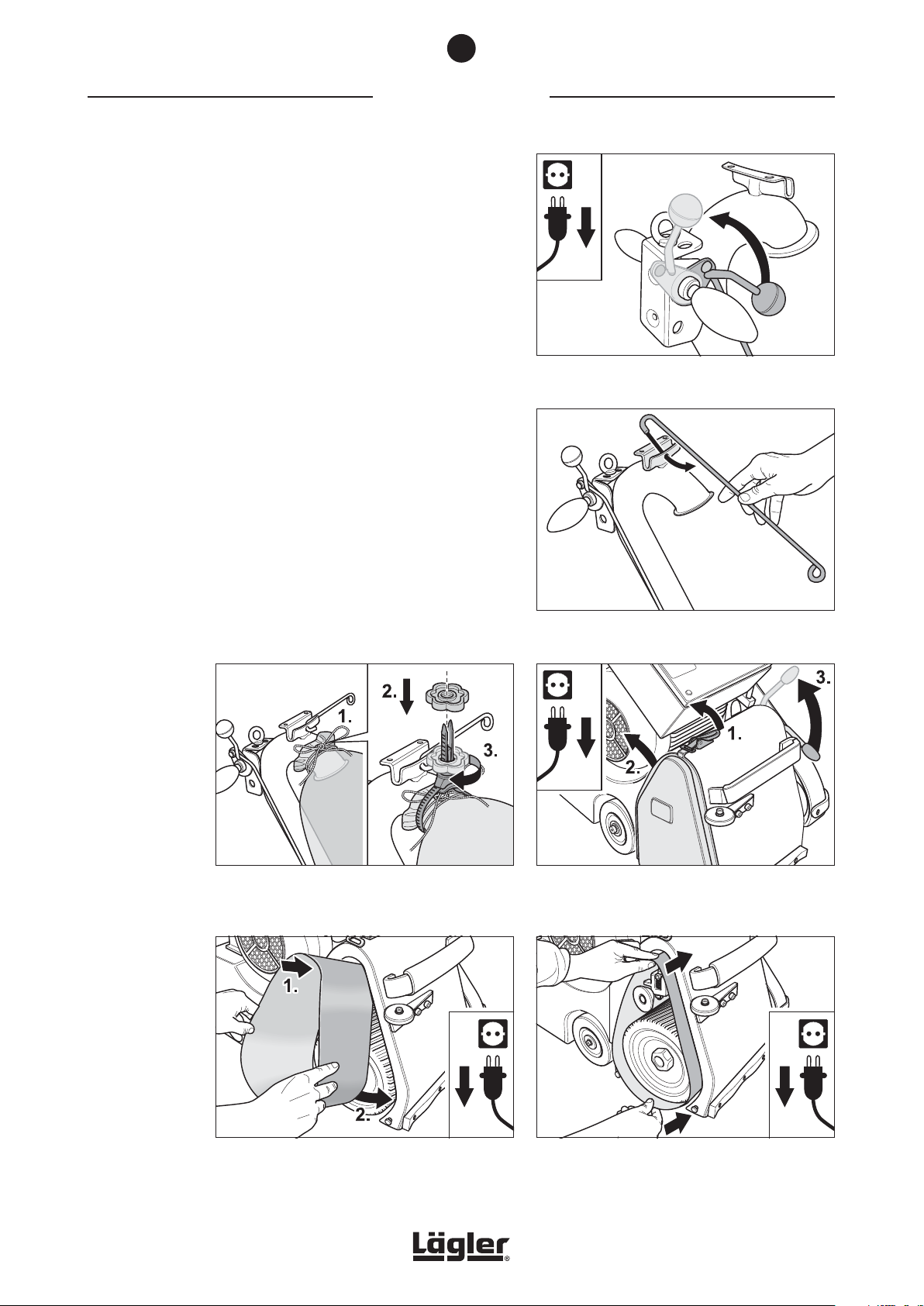
5 Lift the sanding drum off the floor by turning the lowering
lever at the handle upwards (Fig. 5).
6 Hook the cable support into the bracket at the top of the guide
tube (Fig. 6)
7 Fasten the dust bag firmly using the cord and the MultiClip
at the end of the guide tube (Fig. 7). Ensuring when mounting
that the opening of the guide tube is not closed.
8 Release the cover lock (Fig. 8, 1.) and remove the side cover
on the right of the machine housing (Fig. 8, 2.).
9 Pull the operating lever of the drive unit upwards (Fig. 8, 3.).
This will lower the tensioning roller.
10 Position the sanding belt on the tensioning roller of the drive
unit (Fig. 9) and push it over the tensioning roller and the
sanding drum (Fig. 10).
Fig. 5 Lift the sanding drum off the floor by turning the
lowering lever at the handle upwards.
Fig. 6 Hook the cable support into the bracket at the
guide tube.
HUMMEL® 01.12.2012
English / Englisch
Fig. 7 Mount the dust bag using the cord (1.) and the
MultiClip (2. and 3.) at the end of the guide tube.
Fig. 9 Position the sanding belt on the tensioning roller
of the drive unit.
Fig. 8 Release the cover lock (1.), remove the side
cover (2.) and lower the tensioning roller by pulling
up the operating lever (3.).
Fig. 10 Push the sanding belt far enough over the sanding
drum and tensioning roller so that the sanding
drum is fully covered by the sanding belt.
13
Page 14
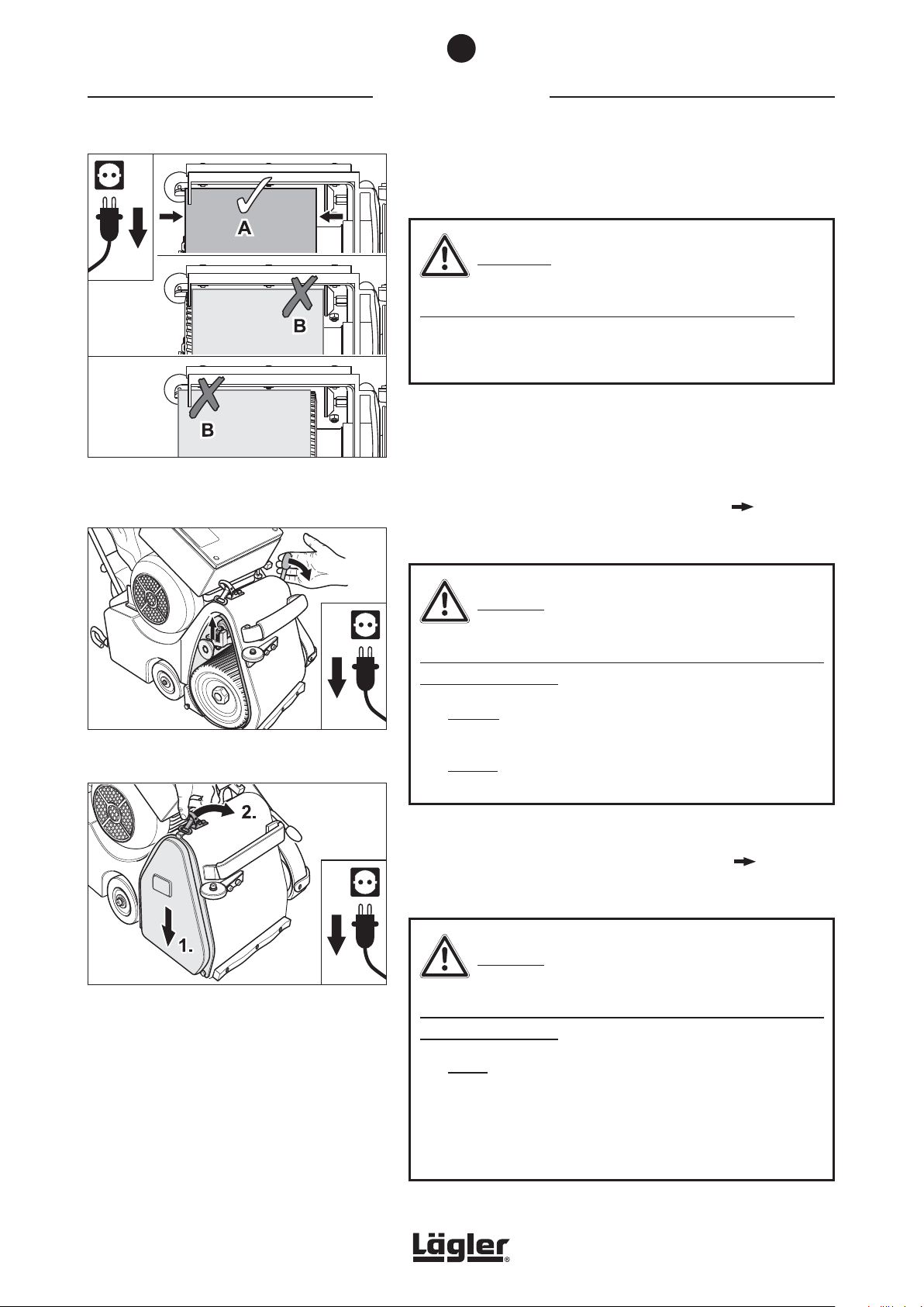
Fig. 11 Position the sanding belt so that it evenly covers
the sanding drum (A). Avoid position B without
fail (risk of fire)!
4
COMMISSIONING
11 Position the sanding belt so that it evenly covers the sanding
drum (Fig. 11, A).
WARNING!
RISK OF FIRE from the formation of sparks while sanding:
Position B of the sanding belt in Fig. 11 provoke sparking during
sanding! Avoid this without fail!
12 To tension the sanding belt, press the operating lever of the
drive unit downwards (Fig. 12). Otherwise, damage or injury
can occur!
13 Connect the machine to the mains supply ( Section 4.2,
Connecting the power cable).
Fig. 12 Tension the sanding belt by lowering the operating
lever. Otherwise, damage or injury can occur!
Fig. 13 Mount the side cover.
CAUTION!
RISK OF INJURY and RISK OF PROPERTY DAMAGE from rotating
parts of the machine:
• Always tension the sanding belt before switch on the
machine (Fig. 12)!
• Always lift the sanding drum off the floor before switch on
the machine (Fig. 14)!
14 Before sanding, the precise tracking of the sanding belt
must be checked! Adjusted it if necessary ( Section 7.3,
Checking and setting the sanding belt tracking)!
CAUTION!
RISK OF INJURY and RISK OF PROPERTY DAMAGE from rotating
parts of the machine:
14
• Never reach into the area of the sanding belt while it is
running!
• During the test run, ensure that no objects randomly
positioned in the vicinity can be picked up by the sanding
belt and no other persons are in the danger area!
HUMMEL® 01.12.2012
English / Englisch
Page 15
4
COMMISSIONING
15 After the checking and setting of the sanding belt tracking
mount the side cover (Fig. 13).
16 The machine is now ready for operation ( Section 4.3,
Switching on the machine).
4.2 CONNECTING THE POWER CABLE
WARNING!
RISK OF DEATH from electrical shock:
• To protect yourself and the machine against faults in the
mains supply use a safety switch PRCD (for German mains
supply Part number in Section 11, Spare parts)!
• Observe the applicable regulations and legal requirements
for your country!
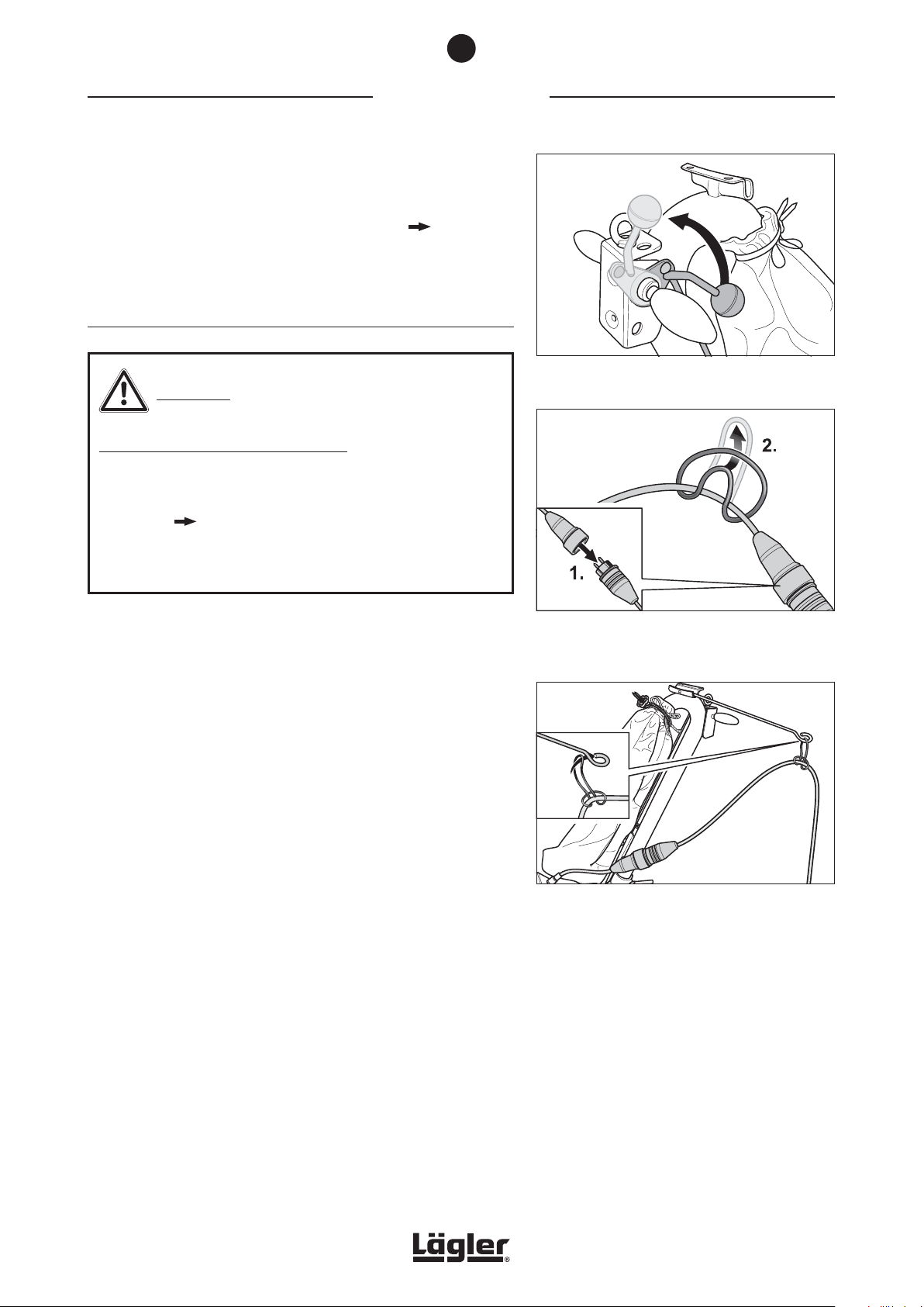
1 Lift the sanding drum off the floor by turning the lowering
lever at the handle upwards (Fig. 14).
2 Insert the plug of the motor cable in the coupler of the
extension cable (Fig. 15, 1.).
3 Fasten the strain relief ring on the extension cable (Fig. 15, 2.)
and mount the strain relief ring on the cable support (Fig. 16).
Fig. 14 Lift the sanding drum off the floor by turning the
lowering lever at the handle upwards.
Fig. 15 Insert the plug of the motor cable in the coupler
of the extension cable (1.). Fasten the strain relief
ring on the extension cable (2.).
4 Plug in the extension cable to a adequately fused mains socket
with PE contacts.
HUMMEL® 01.12.2012
English / Englisch
Fig. 16 Mount the strain relief ring on the cable support.
15
Page 16
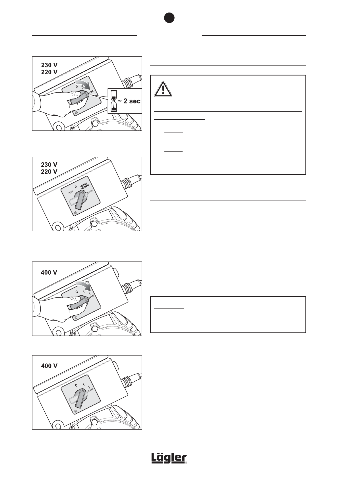
Fig. 17 To switch on the machine turn the switch button at
the motor to position -START- and hold the switch
button for around 2 seconds in this position.
4
COMMISSIONING
4.3 SWITCHING ON THE MACHINE
CAUTION!
RISK OF INJURY and RISK OF PROPERTY DAMAGE from rotating
parts of the machine:
• Always tension the sanding belt before switch on the
machine (Fig. 12)!
• Always lift the sanding drum off the floor before switch on
the machine (Fig. 14)!
• Never allow the machine to run unattended!
Fig. 18 Once the motor has reached its full speed,
release the switch button. The switch button will
then automatically move to position -BETRIEB
(WORKING)-.
Fig. 19 To switch on the machine turn the switch button
at the motor to position -START-.
4.3.1 MACHINES WITH SINGLE-PHASE AC MOTOR (MAINS VOLTAGE 230 V AND 220 V)
1 Lift the sanding drum off the floor by turning the lowering
lever at the handle upwards (Fig. 14)!
2 To switch on the machine turn the switch button at the motor
to position -START- and hold the switch button for around 2
seconds in this position (Fig. 17).
3 Once the motor has reached its full speed, release the switch
button. The switch button will then automatically move to
position -BETRIEB (WORKING)- (Fig. 18).
ATTENTION!
Remaining for too long in the switch position -START- shortens
the service life of the starting capacitor!
4.3.2 MACHINES WITH THREE-PHASE AC MOTOR (MAINS VOLTAGE 400 V)
Fig. 20 Release the switch button. The button turns
automatically in position -1-.
16
1 Lift the sanding drum off the floor by turning the lowering
lever at the handle upwards (Fig. 14)!
2 To switch on the machine turn the switch button at the motor
to position -START- (Fig. 19) and release the switch button
after the motor has reached its full speed. The switch button
will then automatically move to position -1- (Fig. 20).
HUMMEL® 01.12.2012
English / Englisch
Page 17
4
COMMISSIONING
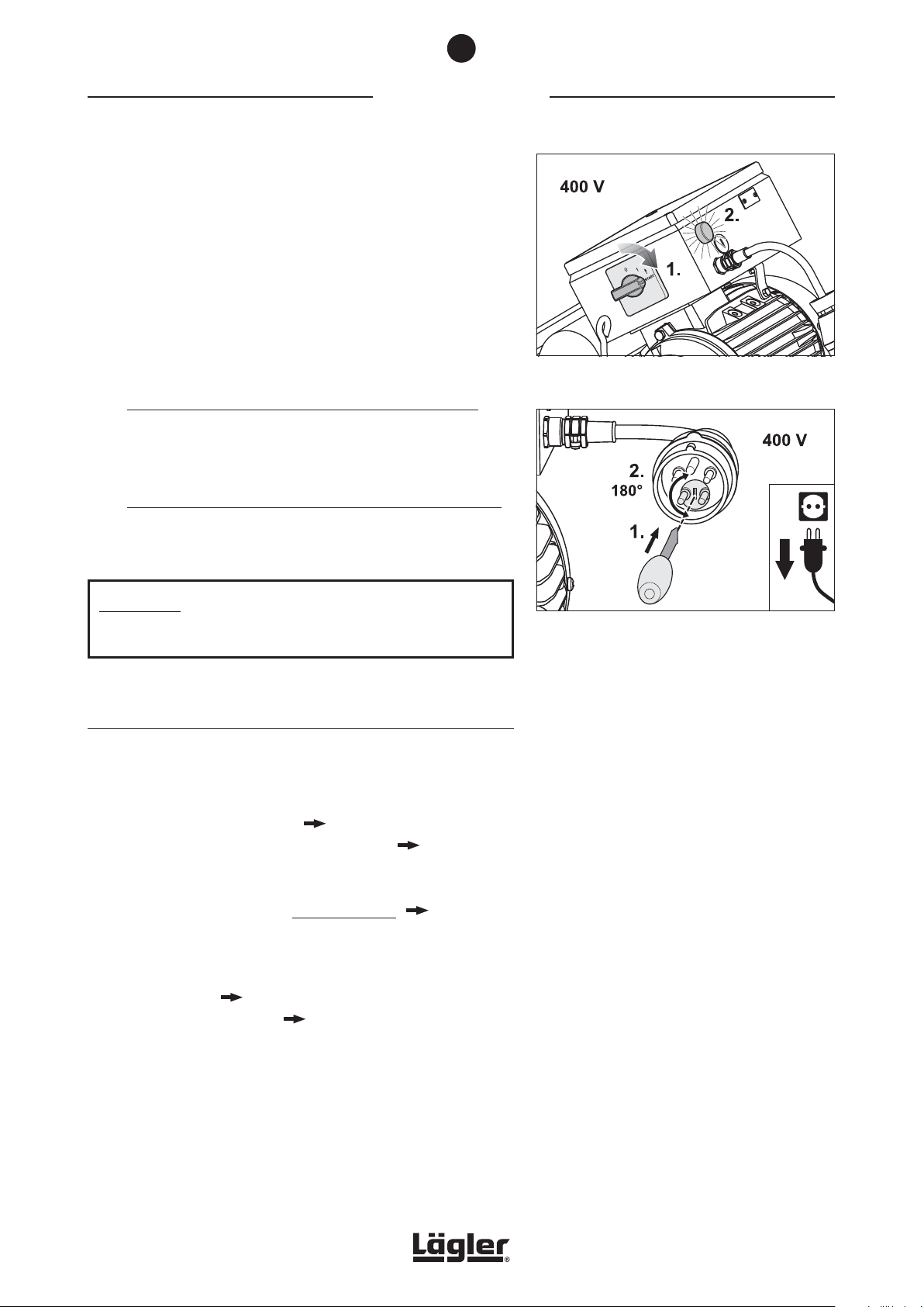
If the motor do not start in the switch position -START- (Fig. 21, 1.)
and the light on the switch box shines (Fig. 21, 2.), the rotation
direction of the motor is wrong.
To change the rotation direction of the motor using the following
procedure:
1 Disconnect the motor cable from extension cable.
2 Put a screwdriver in the slit of the phase changing switch in
the plug of the motor cable (Fig. 22, 1.).
3 Original LÄGLER® plug with red nut at the cable outlet:
To unlock the phase changing switch press the screwdriver
in the slit and at the same time turn the screwdriver at 180°
(Fig. 22, 2.).
Original LÄGLER® plug with yellow nut at the cable outlet:
To unlock the phase changing switch turn the screwdriver at
180° against a small resistance (Fig. 22, 2.).
Fig. 21 The motor do not start in switch position -START-
(1.) and the light on the switch box shines (2.).
ATTENTION!
The phase changing switch can only be turned in one direction!
4.3.3 GENERAL
If the motor should ever be difficult to start in extremely cold
conditions proceed as follows:
1 Switch off the machine ( Section 4.4, Switching off
the machine) and remove the V-belts ( Section 7.10,
Replacement and tensioning of V-belts).
2 Switch on the machine without V-belts ( Section 4.3,
Switching on the machine).
3 Once the motor is up to operating temperature, switch off
the machine ( Section 4.4, Switching off the machine)
and mount the V-belts ( Section 7.10, Replacement and
tensioning of V-belts).
Fig. 22 Change the rotation direction of the motor by
turning the phase changing switch at 180°.
HUMMEL® 01.12.2012
English / Englisch
17
Page 18
4
COMMISSIONING
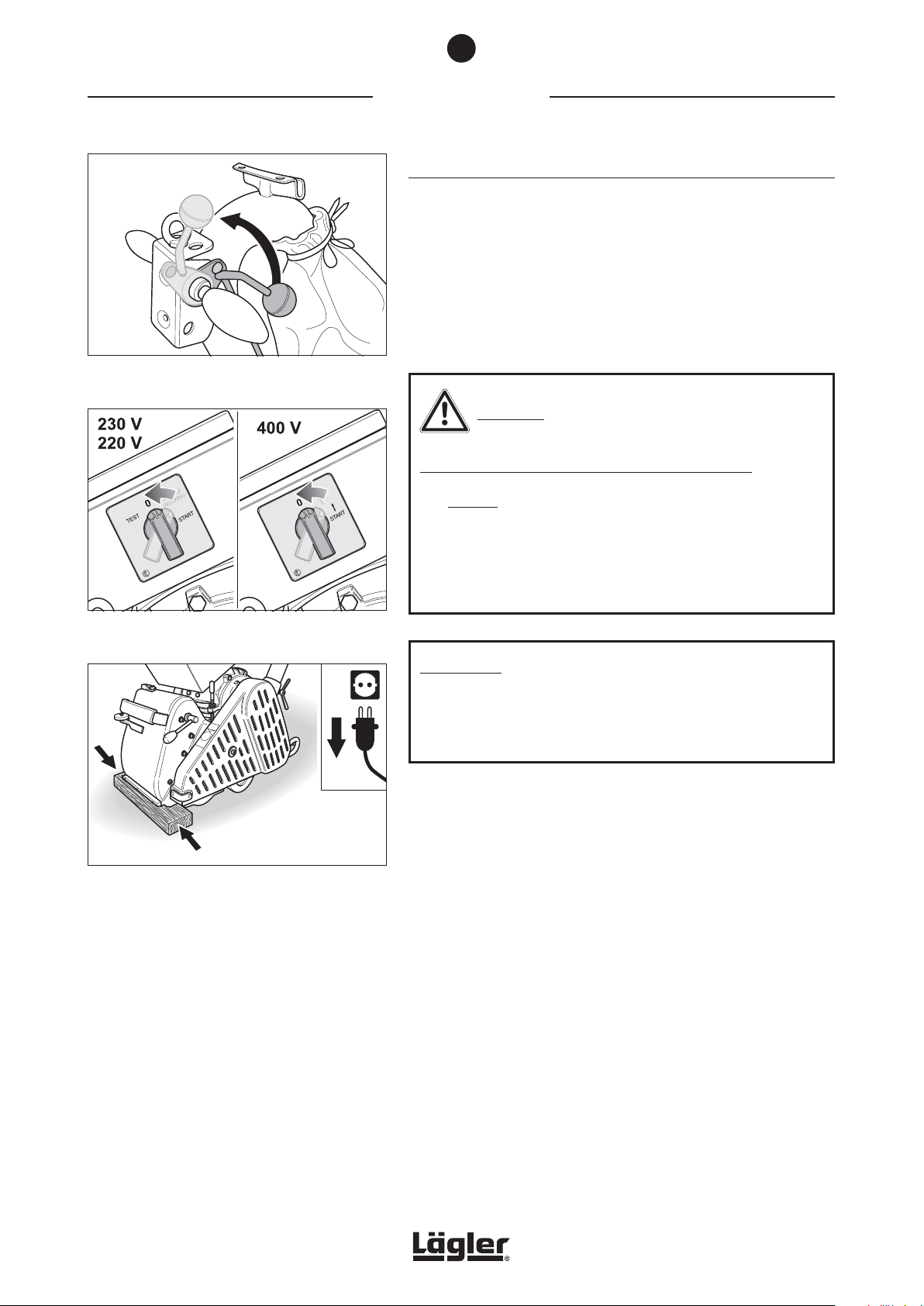
4.4 SWITCHING OFF THE MACHINE
1 Before switch off the machine lift the sanding drum off the
floor by turning the lowering lever at the handle upwards
(Fig. 23).
2 Turn the switch button to position -0- (Fig. 24).
3 Wait until the sanding drum comes to a standstill!
Fig. 23 Lift the sanding drum off the floor by turning the
lowering lever at the handle upwards.
Fig. 24 To switch off the machine turn the switch button
to position -0-.
CAUTION!
RISK OF INJURY and RISK OF PROPERTY DAMAGE:
• Always remove the power plug from the socket after you
have switched off the machine!
• Secure the machine against sliding! For example, place a
flat piece of wood between the floor surface and machine
housing (Fig. 25).
ATTENTION!
Do not store the unused machine on the sanding drum!
Otherwise the sanding media can cause scratches on the
ground or the sanding drum can be damaged!
Fig. 25 Secure the machine against sliding!
18
HUMMEL® 01.12.2012
English / Englisch
Page 19
5
WORKING WITH THE HUMMEL
Working with the HUMMEL
5.1 APPLICATION TIPS
ATTENTION!
• Always sand from left to right! This ensures that the lefthand lateral wheel always runs over the newly sanded
surface, making the surface more even with each sanding
pass and preventing waviness!
• One sanding track comprises a forward and reverse
movement over the same lane without offset!
• We advise a sanding track offset of 50%!
®
®
WARNING!
RISK OF DEATH from electrical shock:
The machine may never be used for wet
processing operations of any kind!
• Deep sanding marks due to the selection of a too coarse grit
grade can be prevented by starting the first sanding operation
with the finest grit grade possible.
• Carry out a test sanding process using a 50 or 60 grit grade
(a few test sanding tracks). If this test is satisfactory and you
envisage a good sanding result within a reasonable period,
it is more efficient to start the sanding work with these finer
grit grade.
• Prevent sanding marks made by previously used grit grade by
adhering to the order of the sandpaper grit grade and never
skip more than one grit grade.
• Always vacuum the floor thoroughly before the first sanding
operation and after each additional one.
• Clean the wheels of the machine before starting each new
sanding operation.
• In order to avoid chatter marks, use sanding belts with bud
joints and tape.
NOTE:
For more information free of charge, please
contact: within Germany
- Telephone: 0800 / 52 34 537
- Fax: 0800 / 48 66 353
within the USA
- Telephone: 800-848-6635
or
- Telephone: 0049 - 7135 - 98 90 - 0
- Fax: 0049 - 7135 - 98 90 - 98
- E-mail: [email protected]
- Internet: http://www.laegler.com
You will also find important and interesting
application tips in the LÄGLER® application
technique guidelines “Sanding of wooden
floors” (http://www.laegler.com)!
• After replacing the sanding belt, start working in poorly lit
areas of the room in order to remove the initial aggressiveness
of the sanding medium.
HUMMEL® 01.12.2012
English / Englisch
19
Page 20
5
WORKING WITH THE HUMMEL
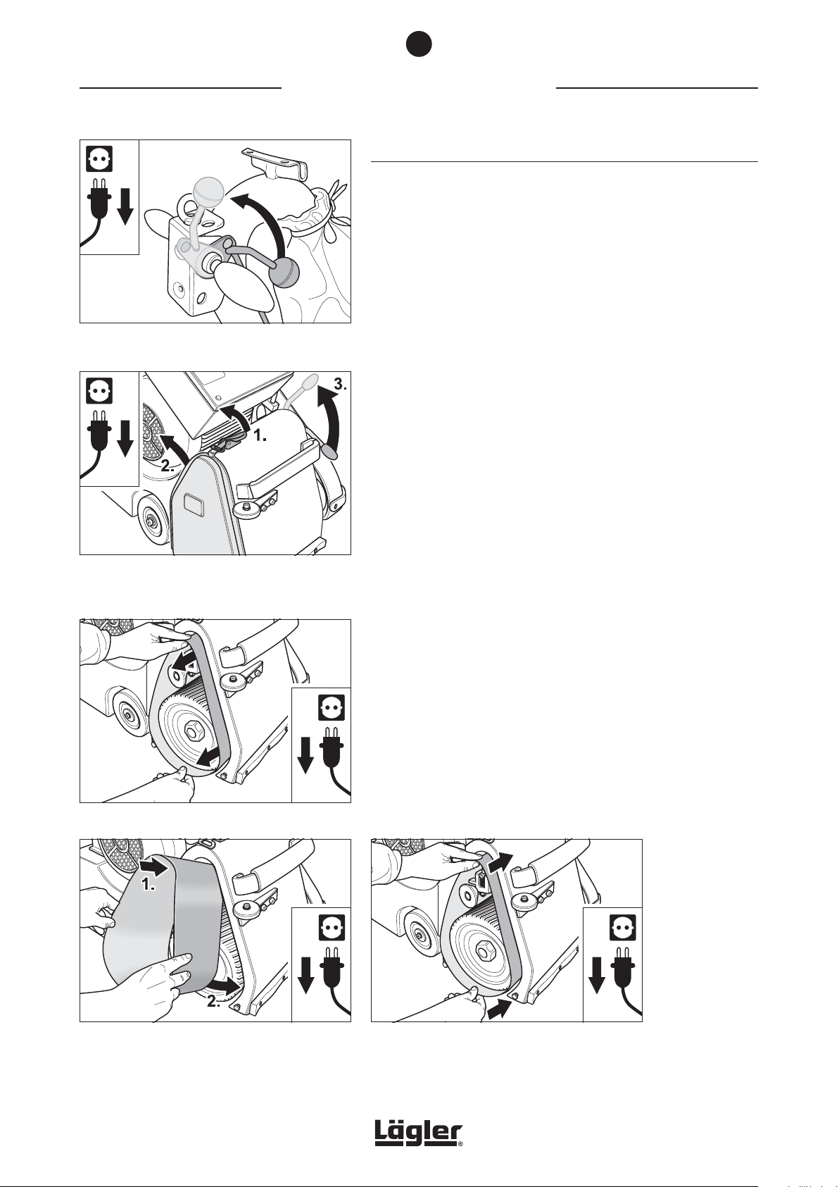
Fig. 26 Lift the sanding drum off the floor by turning the
lowering lever at the handle upwards.
®
5.2 CHANGING THE SANDING BELT
Depending on the type of sanding process you wish to perform,
different abrasive grit grades can be selected. In order to change
the abrasive, proceed as follows:
1 Lift the sanding drum off the floor by turning the lowering
lever at the handle upwards (Fig. 26).
2 Switch off the machine and pull the power plug out of the
socket!
3 Release the cover lock (Fig. 27, 1.) and remove the side cover
on the right of the machine housing (Fig. 27, 2.).
4 To release the tension of the sanding belt, pull the operating
lever of the drive unit upwards (Fig. 27, 3.). This will lower the
tensioning roller.
Fig. 27 Release the cover lock (1.), remove the side
cover (2.) and lower the tensioning roller by pulling
up the operating lever (3.).
Fig. 28 Remove the sanding belt.
5 Remove the worn sanding belt from the tensioning roller and
the sanding drum (Fig. 28).
6 Position the new sanding belt on the tensioning roller of the
drive unit (Fig. 29) and push it over the tensioning roller and
the sanding drum (Fig. 30).
Fig. 29 Position the new sanding belt on the tensioning
roller of the drive unit.
20
Fig. 30 Push the sanding belt far enough over the sanding
drum and tensioning roller so that the sanding
drum is fully covered by the sanding belt.
HUMMEL® 01.12.2012
English / Englisch
Page 21
5
WORKING WITH THE HUMMEL
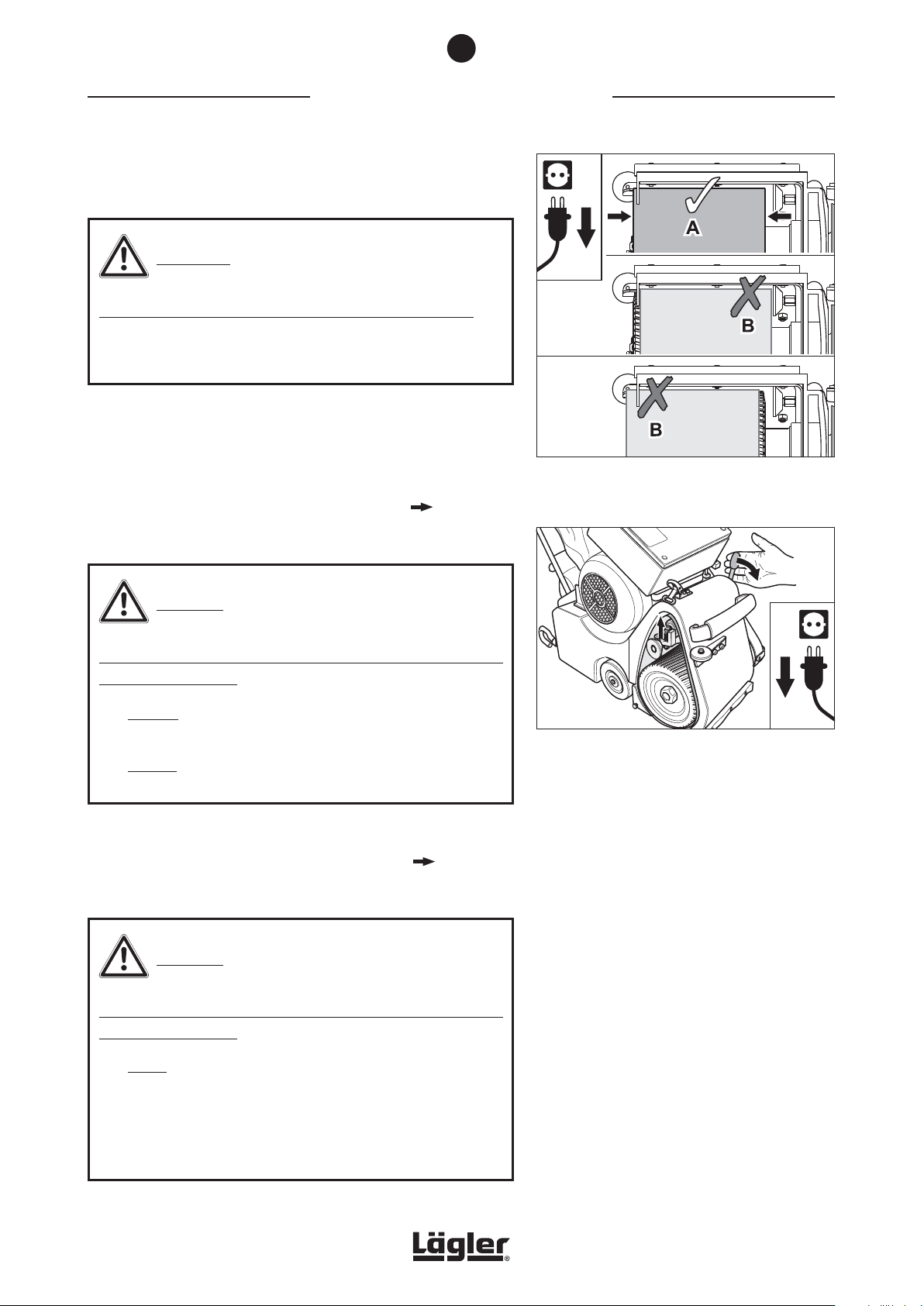
7 Position the sanding belt so that it evenly covers the sanding
drum (Fig. 31, A).
WARNING!
RISK OF FIRE from the formation of sparks while sanding:
Position B of the sanding belt in Fig. 31 provoke sparking during
sanding! Avoid this without fail!
8 To tension the sanding belt, press the operating lever of the
drive unit downwards (Fig. 32). Otherwise, damage or injury
can occur!
9 Connect the machine to the mains supply ( Section 4.2,
Connecting the power cable).
®
Fig. 31 Position the sanding belt so that it evenly covers
the sanding drum (A). Avoid position B without
fail (risk of fire)!
CAUTION!
RISK OF INJURY and RISK OF PROPERTY DAMAGE from rotating
parts of the machine:
• Always tension the sanding belt before switch on the
machine (Fig. 32)!
• Always lift the sanding drum off the floor before switch on
the machine (Fig. 26)!
10 Before sanding, the precise tracking of the sanding belt
must be checked! Adjusted it if necessary ( Section 7.3,
Checking and setting the sanding belt tracking)!
CAUTION!
RISK OF INJURY and RISK OF PROPERTY DAMAGE from rotating
parts of the machine:
Fig. 32 Tension the sanding belt by lowering the operating
lever. Otherwise, damage or injury can occur!
• Never reach into the area of the sanding belt while it is
running!
• During the test run, ensure that no objects randomly
positioned in the vicinity can be picked up by the sanding
belt and no other persons are in the danger area!
HUMMEL® 01.12.2012
English / Englisch
21
Page 22
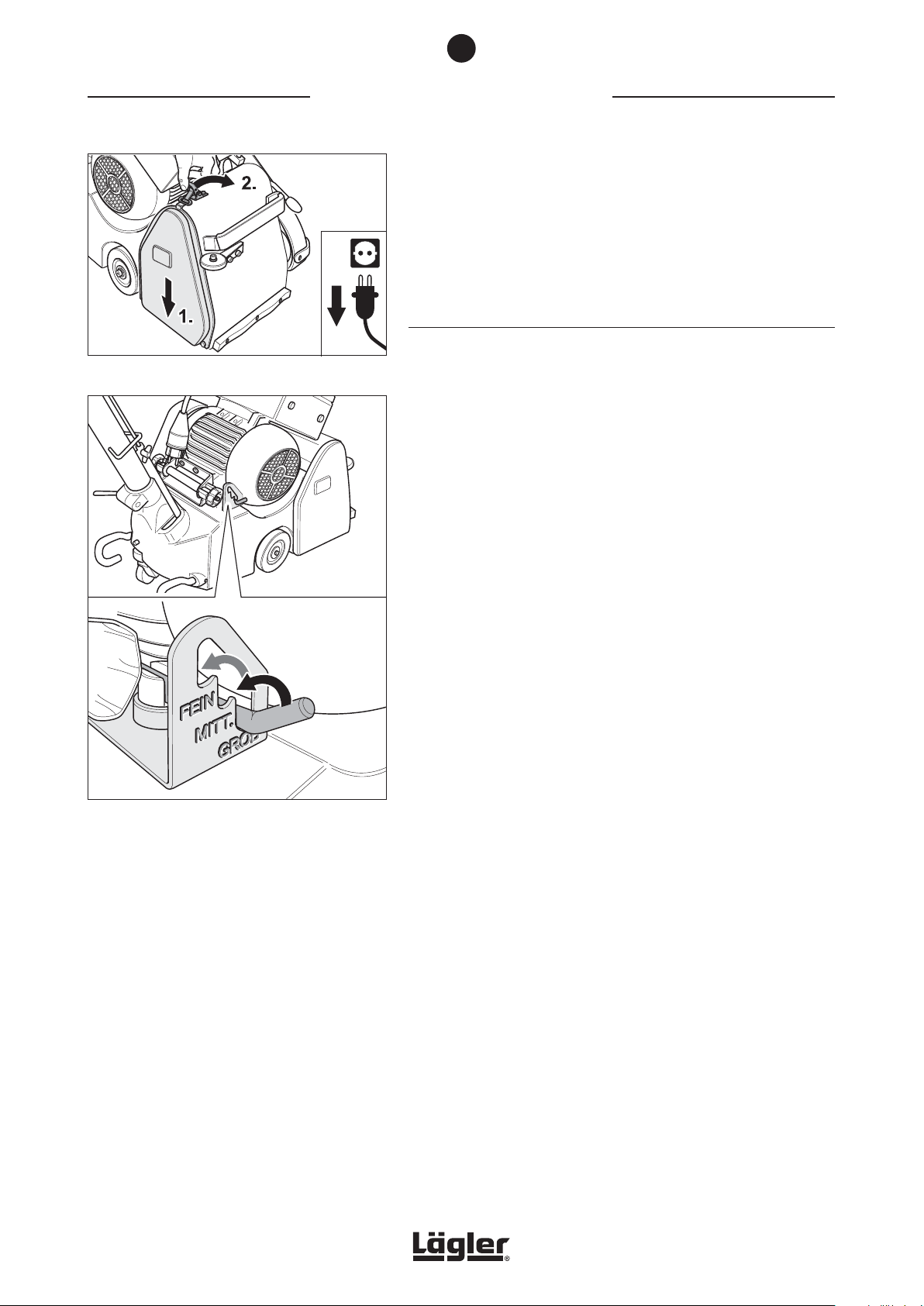
5
Fig. 33 Mount the side cover.
WORKING WITH THE HUMMEL
11 After the checking and setting of the sanding belt tracking
mount the side cover (Fig. 33).
12 It is now possible to execute the next sanding process with
the machine.
5.3 REGULATING THE SANDING DRUM PRESSURE
The lever can be used to set three different drum pressure stages.
These three stages - COARSE / MEDIUM / FINE - are designated on
the notch plate as -GROB / MITT. / FEIN- (Fig. 34).
The pressure stage indications relate to the grit grade sequence.
The sanding pressure should be adjusted inline with the grit grade
sequence and reduced as the fineness of the grit grade increases.
This setting facility permits you to adjust the drum pressure to the
prevailing circumstances.
®
Fig. 34 Different sanding pressure stages can be selected
using the setting lever.
GROB (COARSE) = high sanding pressure for coarse grit grade
MITT. (MEDIUM) = middle sanding pressure for medium grit
grade
FEIN (FINE) = low sanding pressure for fine grit grade
In order to avoid dish-outs when sanding soft wood floors, the
sanding pressure should be reduced and the sanding speed
increased.
22
HUMMEL® 01.12.2012
English / Englisch
Page 23
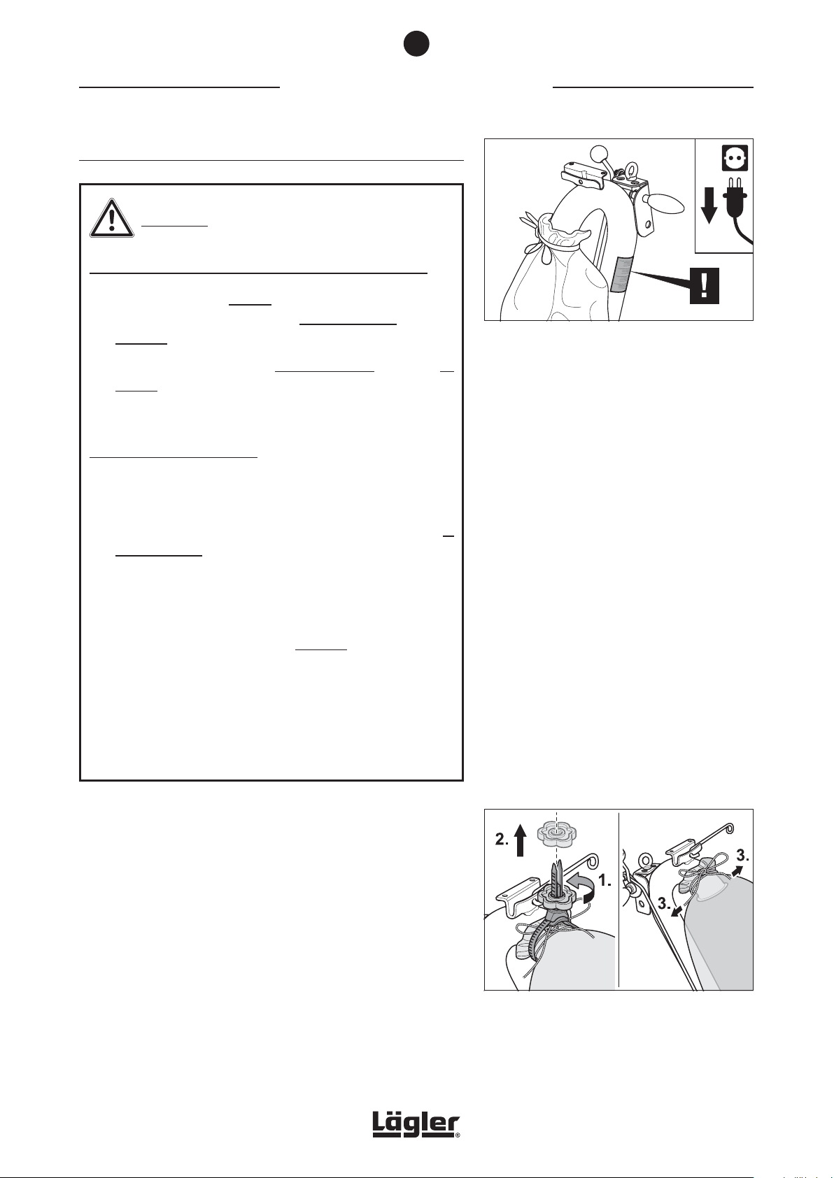
5
WORKING WITH THE HUMMEL
5.4 EMPTYING THE DUST BAG
WARNING!
RISK OF FIRE from the formation of sparks while sanding:
• The dust bag must always be removed from the machine
after sanding and emptied into a non-combustible container
outdoors!
• Cover this container with a non-combustible cover and be
certain to store it and the dust bag outdoors!
• Note the warning on the guide tube (Fig. 35)!
HEALTH RISK caused by dust:
In order to ensure that the dust values in the air do not exceed
the prescribed threshold levels, please note:
®
Fig. 35 Note the warning on the guide tube!
• The dust bag must be emptied when it is one-third full at
the very latest in order to prevent a deterioration of the
suction performance due to the lack of filtering surface
area!
• Do not work with an overfilled dust bag!
• The dust bag must be emptied outdoors!
• When emptying the dust bag, wear a respiratory protective
mask (at least filter class P2)!
• Do not wash, patch or repair the dust bag in any other
manner!
• Damaged dust bags must be replaced with new ones!
Use exclusively original LÄGLER® dust bags for the HUMMEL® (Part
number in Section 11, Spare parts)!
1 Switch off the machine and pull the power plug out of the
socket!
2 Wear the respiratory protective mask (at least filter class
P2)!
3 Remove the MultiClip (Fig. 36, 1. and 2.) and open the cord at
the dust bag (Fig. 36, 3.).
4 Take the dust bag away and close it with the cord.
HUMMEL® 01.12.2012
English / Englisch
Fig. 36 Remove the MultiClip (1. and 2.) and open the cord
at the dust bag (3.).
23
Page 24
6
TRANSPORT AND STORAGE
5 Empty the dust bag into a non-combustible container outdoors
and cover this container with a non-combustible cover
(RISK OF FIRE)!
6 Fasten the empty dust bag firmly using the cord and the
MultiClip at the end of the guide tube. Ensuring when mounting
that the opening of the guide tube is not closed. Wear the
respiratory protective mask!
6
Transport and storage
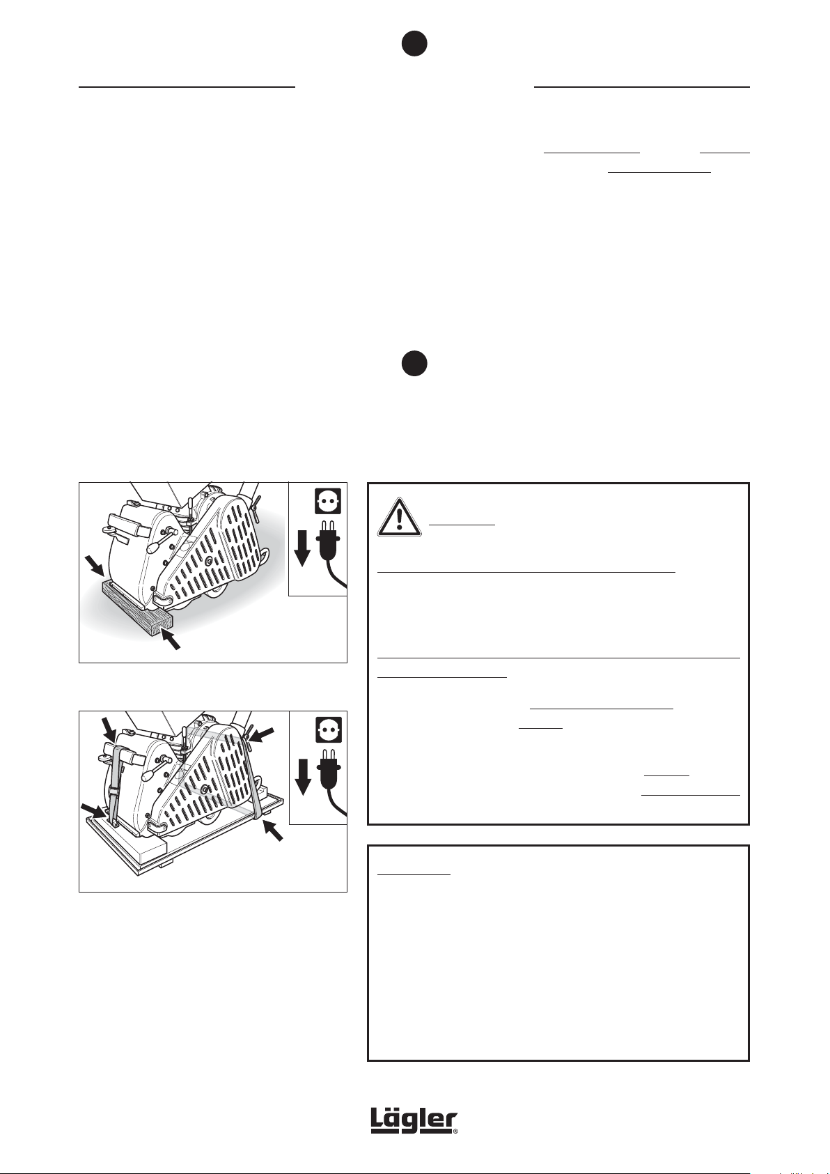
Fig. 37 Transport or storage of the machine on a flat piece
of wood.
Fig. 38 Transport or storage of the machine on the bottom
part of the transport crate.
WARNING!
RISK OF INJURY and RISK OF PROPERTY DAMAGE:
In the event of transport in an automobile or similar machine,
all parts must be secured against sliding!
RISK OF FIRE from spontaneous combustion or the formation of
sparks while sanding:
• Oil or wax can lead to spontaneous combustion! Therefore,
the machine must always be cleaned carefully before
transport or storage!
• Always transport and store the machine without the dust
bag! Store the used dust bag in a closed non-combustible
container!
ATTENTION!
• During transport or storage, place a flat piece of wood
between the floor surface and machine housing (Fig. 37)!
This prevents the housing from slipping and stops the drum
being in direct contact with the floor!
24
• During transport or storage, the machine can also be firmly
lashed to the bottom part of the supplied transport crate
using two belts (Fig. 38)! This will prevent damage to the
sanding drum and stop the wheels becoming out of round!
HUMMEL® 01.12.2012
English / Englisch
Page 25
6
TRANSPORT AND STORAGE
6.1 DISMANTLING THE MACHINE BEFORE TRANSPORTATION
For transportation, the machine can be dismantled into three parts:
Guide tube, motor and machine housing. During manual transport
over roads and pavements, to protect the wheels and sanding drum,
use the TransCart (Part number in Section 11, Spare parts).
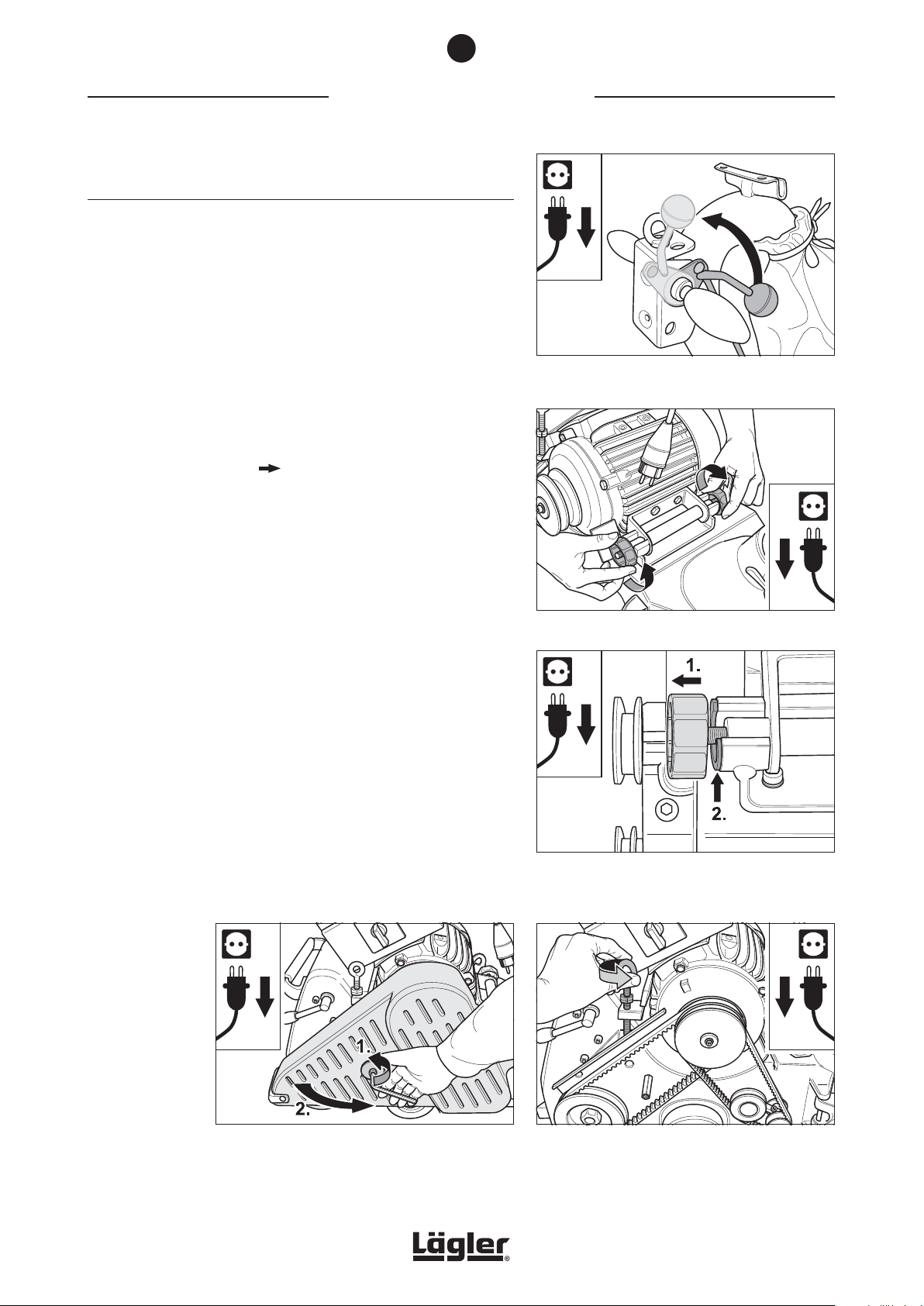
1 Switch off the machine and pull the power plug out of the
socket!
2 Lift the sanding drum off the floor by turning the lowering
lever at the handle upwards (Fig. 39).
3 Empty the dust bag ( Section 5.4, Emptying the dust bag).
Fig. 39 Lift the sanding drum off the floor by turning the
lowering lever at the handle upwards.
4 Loosen the two motor nuts at the motor bearing bracket
(Fig. 40).
The motor nut must only be backed out from the fitting
between the motor nut and motor bearing bracket, and not
completely removed (Fig. 41).
5 Open the belt guard (Fig. 42).
6 Release the tension of the V-belts by turning the eye bolt at
the motor counterclockwise (Fig. 43).
Fig. 40 Loosen the two motor nuts.
Fig. 41 Turn the two motor nuts out so far (1.) until the two
nuts used to fit into the motor bearing bracket are
exposed (2.).
HUMMEL® 01.12.2012
English / Englisch
Fig. 42 Pull the power plug out of the socket and open
the belt guard.
Fig. 43 Release the tension of the V-belts by turning the
eye bolt at the motor counterclockwise.
25
Page 26
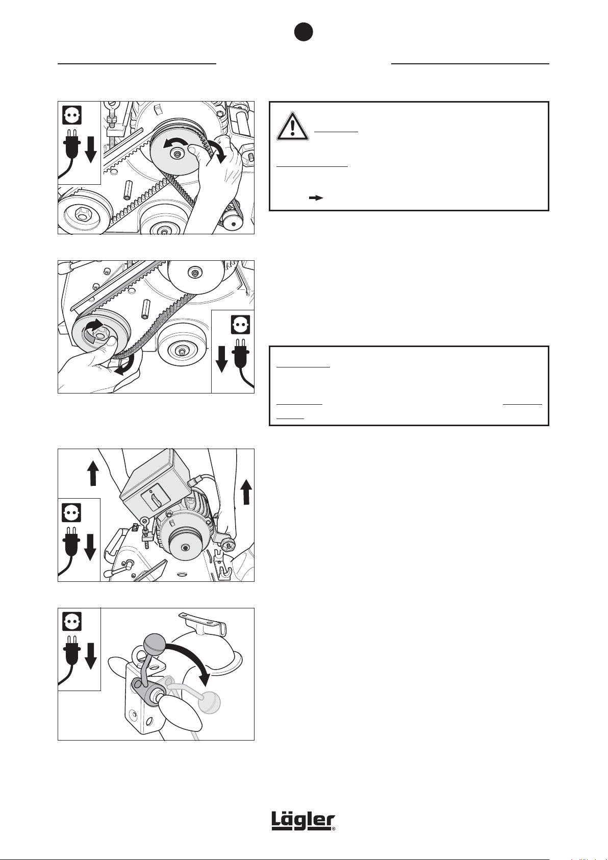
6
TRANSPORT AND STORAGE
CAUTION!
RISK OF INJURY:
During dismantling and mounting the V-belts, take care of your
fingers danger of crushing!
Fig. 44 Remove the suction V-belt.
Fig. 45 Allow the drive V-belt to run off the lower pulley.
If necessary, use the box wrench (see tool kit) to
help you. Turn the pulley exclusively clockwise
in order not to loosen the nut!
7 Turn the motor pulley and allow the suction V-belt to run off
the motor pulley (Fig. 44).
8 Turn the lower pulley and allow the drive belt to run off the
lower pulley (Fig. 45).
If necessary, use the box wrench (see tool kit) to turn the
lower pulley exclusively clockwise!
ATTENTION!
Only turn the nut with the box wrench at the lower pulley
clockwise, as otherwise the nut will work loose (left-hand
thread)!
9 Remove the motor from the machine housing (Fig. 46) and
secure it during transport against slipping and damage!
10 Press the lowering lever at the handle downwards (Fig. 47)
to lower the sanding drum onto the floor.
Fig. 46 Remove the motor from the machine housing.
Fig. 47 Press the lowering lever at the handle downwards
to lower the sanding drum onto the floor.
26
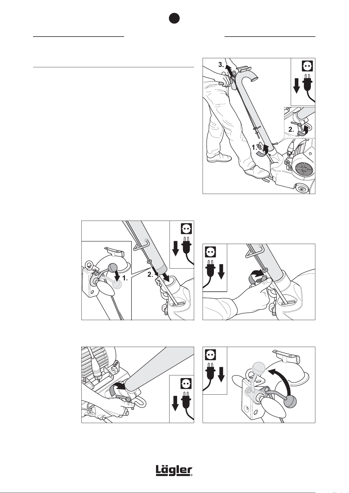
11 Open the wing screw at the lower rod (Fig. 48, 1.) and the wing
nut at the machine housing (Fig. 48, 2.)
12 Pull the guide tube out of the machine housing (Fig. 48, 3.).
HUMMEL® 01.12.2012
English / Englisch
Page 27
6
TRANSPORT AND STORAGE
6.2 ASSEMBLY AFTER TRANSPORTATION
When assembling the HUMMEL® after transport, adhere to the
following sequence of work steps:
1 Press the lowering lever at the handle downwards (Fig. 49, 1.).
2 Insert the guide tube into the opening in the machine housing
and at the same time insert the upper rod into the lower rod
(Fig. 49, 2).
3 Carefully tighten the wing screw at the lower rod (Fig. 50) and
the wing nut at the machine housing (Fig. 51).
4 Lift the sanding drum off the floor by turning the lowering
lever at the handle upwards (Fig. 52).
Fig. 49 When inserting the guide tube, make sure that
the upper rod of the lowering mechanism feeds
in correctly!
Fig. 48 After opening the wing screw (1.) and wing nut
(2.) which fasten the rod linkage, the guide tube
can be drawn out of the machine housing (3.).
Fig. 50 After inserting the guide tube, carefully tighten
the wing screw at the lower rod.
HUMMEL® 01.12.2012
English / Englisch
Fig. 51 After inserting the guide tube, carefully tighten
the wing nut at the machine housing.
Fig. 52 Lift the sanding drum off the floor by turning the
lowering lever at the handle upwards.
27
Page 28
6
TRANSPORT AND STORAGE
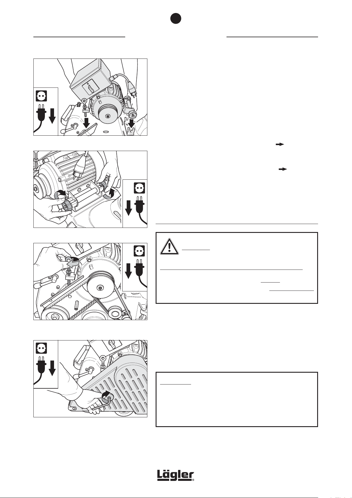
5 Place the motor in the motor bearing bracket (Fig. 53) and
tighten the two motor nuts slightly (Fig. 54).
6 Mount the V-belts and tension them by turning the eye bolt
at the motor clockwise (Fig. 55).
7 Tighten the two motor nuts (Fig. 54).
8 Close the belt guard (Fig. 56).
Fig. 53 Place the motor in the motor bearing bracket.
Fig. 54 Tighten the two motor nuts.
9 Mount the dust bag at he guide tube ( Section 4.1,
Preparing the machine for operation).
10 Connect the machine to the mains supply ( Section 4.2,
Connecting the power cable).
11 The machine is now ready for use.
6.3 STORAGE
WARNING!
RISK OF FIRE from the formation of sparks while sanding:
Always transport and store the machine without the dust bag!
Store the emptied dust bag in a closed non-combustible
container!
Fig. 55 Mount the V-belts and tension them by turning the
eye bolt at the motor clockwise.
Fig. 56 Close the belt guard.
28
If you wish to keep the machine in storage for a protracted period,
ensure that it is kept dry and free of the influence of frost in a location
without excessive temperature fluctuations.
Store your unused machine in a dry, closed location out of the
reach of children!
ATTENTION!
When storing for long periods, place the machine on the bottom
part of the supplied transport crate (Fig. 38)!This will prevent
damage to the sanding drum and stop the wheels becoming
out of round!
HUMMEL® 01.12.2012
English / Englisch
Page 29
7
MAINTENANCE WORK AND REPLACEMENT OF WEARING PARTS
Maintenance work and replacement
of wearing parts
WARNING!
RISK OF DEATH from electrical shock and RISK OF INJURY from
rotating parts of the machine:
• All extensive maintenance work, especially on the electrical
equipment, must be conducted by a qualified expert for
safety reasons!
• All maintenance work must be conducted with the machine
switched off and with the power plug removed from the
socket!
ATTENTION!
• Only use original spare parts from LÄGLER®! This is the
only way to ensure that your machine continues to perform!
Warranty claims for third-party parts will not be honoured!
• Never conduct the maintenance work and replacement
of wearing parts on the newly sanded wooden floor! You
could cause scratches or other damage to the floor!
• Never use any cleaning products which contain solvents!
Periodically but at the latest when you notice that damage
has occurred, a variety of maintenance procedures have to be
performed. For this work, use exclusively original spare parts
from LÄGLER®. Work in a clean, well lit location and proceed in
accordance with these operating instructions. In the tool kit, you
will find all the tools required to carry out the work described below.
It takes only a minimal amount of time to inspect the machine,
but this precautionary measure can save subsequent complaints
brought about by minor damage to the machine. Performing regular
maintenance work will help to retain the value of the machine and
is also in the interests of your own safety.
HUMMEL® 01.12.2012
English / Englisch
29
Page 30
7
MAINTENANCE WORK AND REPLACEMENT OF WEARING PARTS
7.1 CLEANING AND CARE INSTRUCTIONS
WARNING!
RISK OF FIRE from spontaneous combustion and the formation
of sparks while sanding:
• There is a high risk of fire when sanding woods with a
large amount of resin, oiled or waxed floors or metal!
• Therefore, the machine must always be cleaned carefully
directly after sanding!
• Be certain to note the warning notices of the paint, oil and
wax manufacturers!
Before starting work, you should perform the following care
procedure in order to ensure that the machine is in full working
order and produces the customary high-quality sanding finish:
• Check the tensioning roller and the sanding drum for damage.
Clean the parts carefully and ensure that the rubber coating
on the rollers is not damaged.
• Check the sanding belt tracking and adjust it if necessary
using a grit grade 120 sanding belt ( Section 7.3, Checking
and setting the sanding belt tracking).
• Check if the guide rollers at the drive unit and inside the
machine housing are rotatable easily!
Guide rollers which are not rotatable easily provoke sparking
during sanding and must be replaced without fail (Part
number in Section 11, Spare parts)!
• Clean the wheels of the machine.
• Check the tension of the V-belts and correct it if necessary
with the aid of the eye bolt at the motor ( Section 7.10,
Replacement and tensioning of V-belts).
30
• Check that the lowering rod linkage is easy running.
• Check the dust suction system and the dust bag for leaks and
damages.
• Carry out a visual inspection of the electrical equipment
(extension cable, plug, couplings).
HUMMEL® 01.12.2012
English / Englisch
Page 31
7
MAINTENANCE WORK AND REPLACEMENT OF WEARING PARTS
7.1.1 DISMANTLING AND CLEANING OF DRIVE UNIT
The drive unit should be removed and cleaned at least once a week
if the machine is used every day.
ATTENTION!
A dirty drive unit avoids an ideal sanding belt adjustment! This
cause negative effects to the sanding result!
The drive unit is removed using the following procedure:
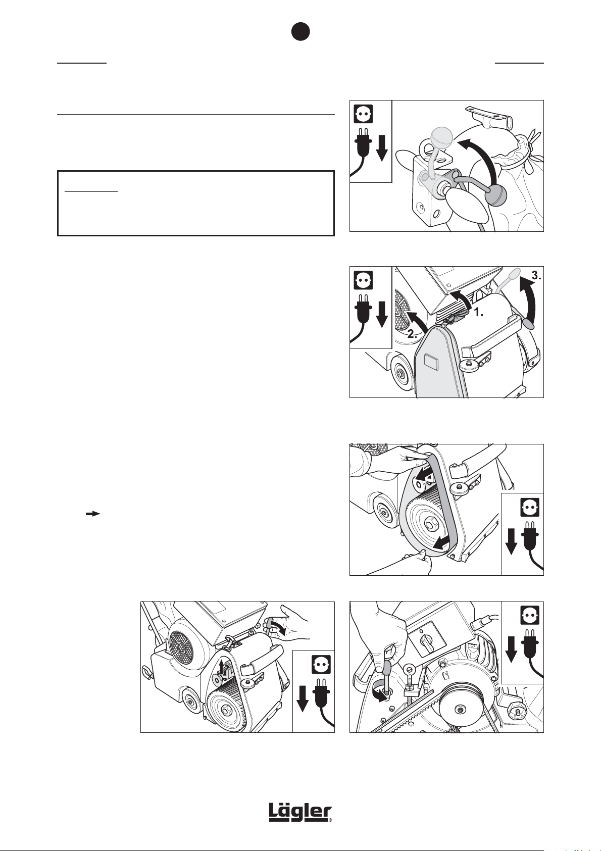
1 Lift the sanding drum off the floor by turning the lowering
lever at the handle upwards (Fig. 57).
2 Switch off the machine and pull the power plug out of the
socket!
3 Release the cover lock (Fig. 58, 1.) and remove the side cover
on the right of the machine housing (Fig. 58, 2.).
4 Pull the operating lever of the drive unit upwards (Fig. 58, 3.).
This will lower the tensioning roller.
5 Remove the sanding belt from the tensioning roller and the
sanding drum (Fig. 59).
6 If you wish to remove the tensioning roller of the drive unit
( Section 7.7, Replacement of tensioning roller), press the
operating lever of the drive unit downwards (Fig. 60).
Fig. 57 Lift the sanding drum off the floor by turning the
lowering lever at the handle upwards.
Fig. 58 Release the cover lock (1.), remove the side cover
(2.) and lower the tensioning roller by pulling up
the operating lever (3.).
7 Remove the operating lever of the drive unit by unscrewing
(Fig. 61).
Fig. 60 Press the operating lever of the drive unit
downwards.
HUMMEL® 01.12.2012
English / Englisch
Fig. 59 Remove the sanding belt.
Fig. 61 Unscrew the operating lever of the drive unit.
31
Page 32
7
MAINTENANCE WORK AND REPLACEMENT OF WEARING PARTS
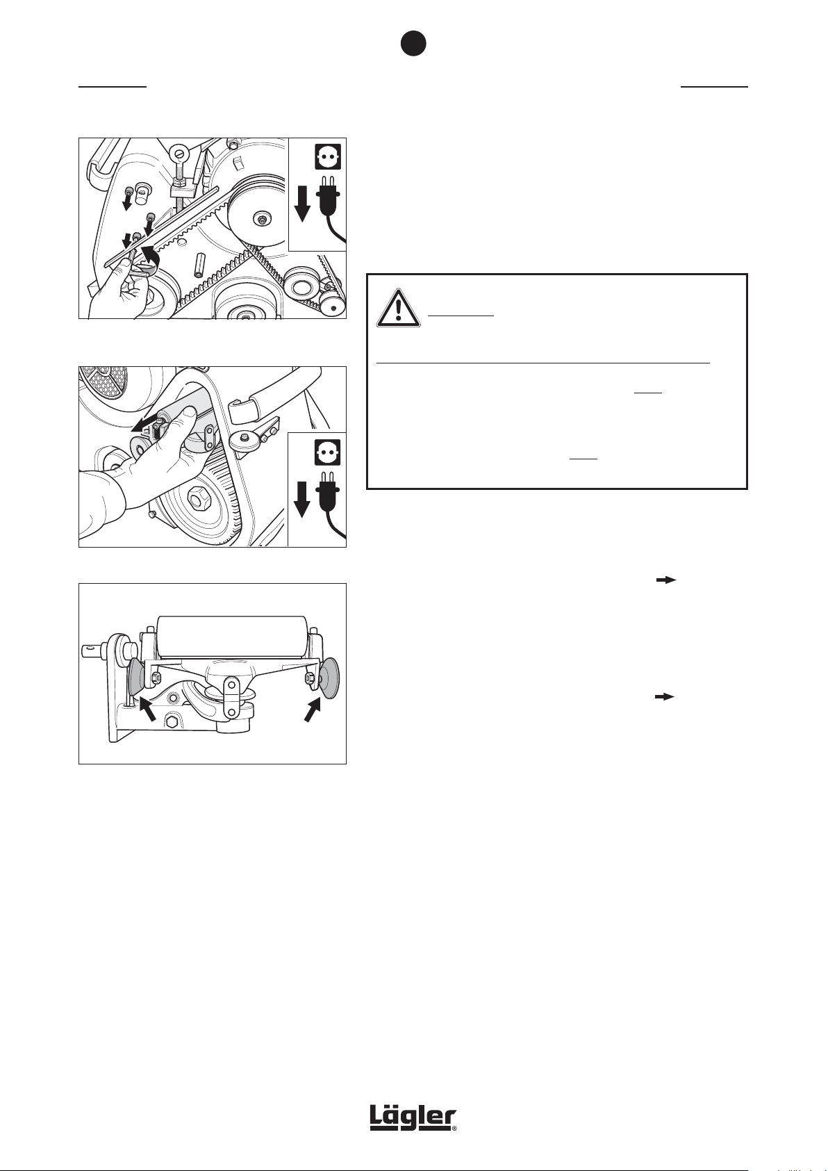
8 Hold on the drive unit and remove the three screws at the
same time (Fig. 62)! Therefore the drive unit cannot fall on
the sanding drum.
9 Carefully remove the drive unit (Fig. 63) and clean it. Never
use any cleaning products which contain solvents!
WARNING!
Fig. 62 Hold on the drive unit and remove the three screws
at the same time.
Fig. 63 Carefully remove the drive unit.
RISK OF FIRE from the formation of sparks while sanding:
• The two guide rollers at the drive unit must be rotatable
easily (Fig. 64)!
• Guide rollers which are not rotatable easily provoke
sparking during sanding and must be replaced without fail
(Part number in Section 11, Spare parts)!
10 Reassemble in reverse order.
11 After mounting the drive unit, check the precise tracking of
the sanding belt and adjust it if necessary ( Section 7.3,
Checking and setting the sanding belt tracking)!
Regular exchange of the sanding drum and tensioning roller
guarantees a constant degree of operating quality and performance.
When working every day with the machine, they must be exchanged
every 1 – 2 years, otherwise every 3 – 4 years ( Section 7.6,
Replacement of sanding drum and Section 7.7, Replacement of
tensioning roller).
Fig. 64 The two guide rollers at the drive unit must
be rotatable easily! Otherwise they must be
replaced!
32
HUMMEL® 01.12.2012
English / Englisch
Page 33
7
MAINTENANCE WORK AND REPLACEMENT OF WEARING PARTS
7.2 LUBRICATION
Machines up to year of manufacture 1997:
For general upkeep of the machine, after around 100 operating hours
we recommend sparing lubrication of the two lubrication nipples
at the wheel bearings using a manual grease gun (tool kit) using
ball bearing grease.
ATTENTION!
In machines from year of manufacture 1998, the lubrication point
at the wheel bearing has been replaced by a self-lubricating
plastic bushing. This bushing does not require lubrication!
Never use sprays such as WD 40 or similar!
In order to guarantee lasting easy running of the moving parts,
lubricate at regular intervals at the following lubrication points
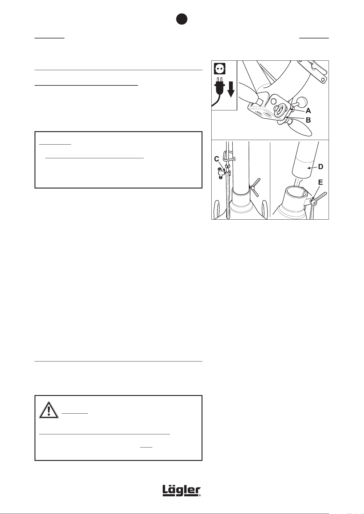
(Fig. 65):
A Top part of the rod linkage at the lever plate
B Lever plate on the handle shaft
To do this, tilt the machine slightly to one side and allow a small
amount of oil to run into the lubrication points.
C Wing screw on the bottom part of the rod linkage
D Guide tube in the machine housing
E Wing nut at the machine housing
Use customary lubricating oil for these lubrication points - never
use grease or sprays such as WD 40 or similar!
7.3 CHECKING AND SETTING THE SANDING BELT TRACKING
The sanding belt tracking must be checked every time the sanding
belt is exchanged, but at least once a day!
Fig. 65 Lubrication points which should be regularly oiled.
CAUTION!
RISK OF INJURY and RISK OF PROPERTY DAMAGE:
During the test run, the sanding drum must be raised off the
floor (Fig. 66)!
HUMMEL® 01.12.2012
English / Englisch
33
Page 34
7
MAINTENANCE WORK AND REPLACEMENT OF WEARING PARTS
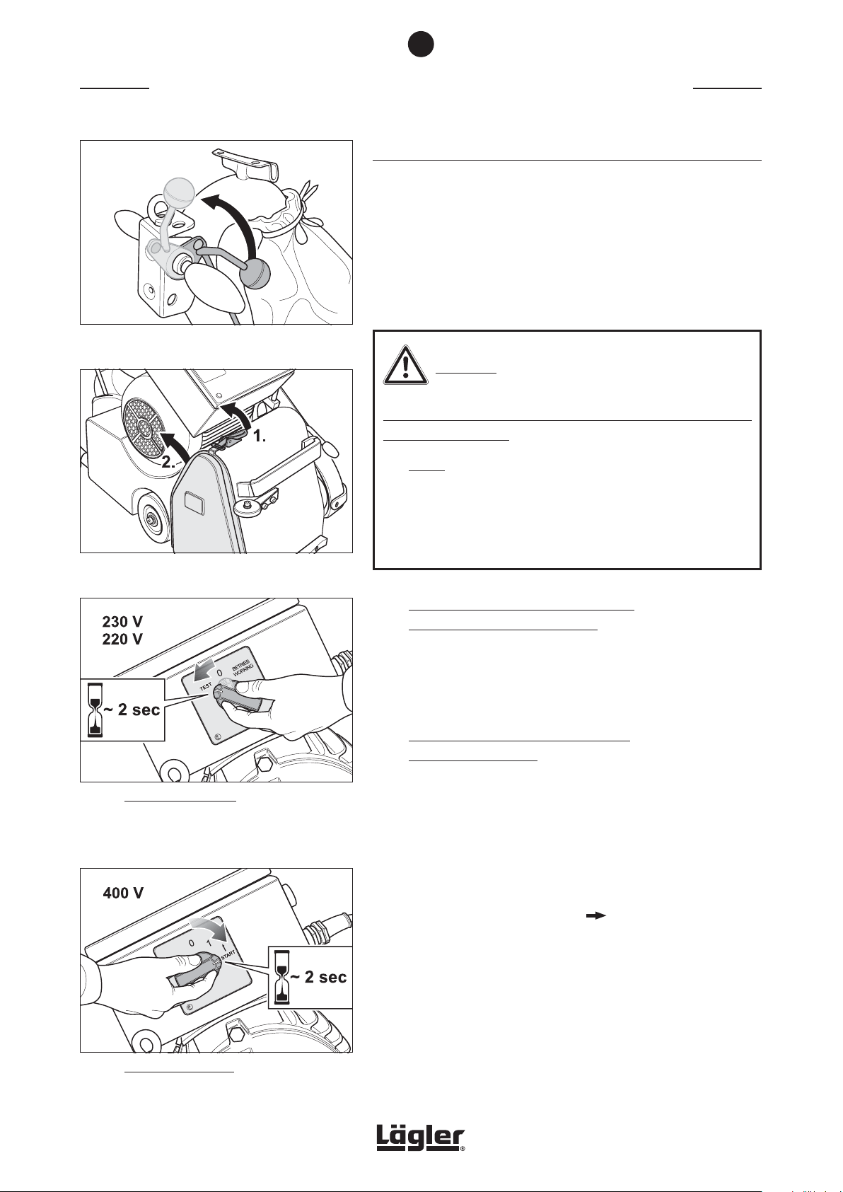
7.3.1 CHECKING THE SANDING BELT TRACKING
1 Lift the sanding drum off the floor by turning the lowering
lever at the handle upwards (Fig. 66)!
2 Switch off the machine!
3 Release the cover lock (Fig. 67, 1.) and remove the side cover
on the right of the machine housing (Fig. 67, 2.).
Fig. 66 Lift the sanding drum off the floor by turning the
lowering lever at the handle upwards
Fig. 67 Release the cover lock (1.) and remove the side
cover (2.).
Fig. 68 Single-phase AC motor:
Hold the switch button for around 2 seconds
in -TEST- position and control the sanding belt
tracking at the same time. After this release the
switch button.
CAUTION!
RISK OF INJURY and RISK OF PROPERTY DAMAGE from rotating
parts of the machine:
• Never reach into the area of the sanding belt while it is
running!
• During the test run, ensure that no objects randomly
positioned in the vicinity can be picked up by the sanding
belt and no other persons are in the danger area!
4 Machines with single-phase AC motor
(mains voltage 230 V and 220 V):
Turn the switch button in position -TEST- and hold the switch
button for around 2 seconds in this position (Fig. 68). At the
same time control the sanding belt tracking. After this release
the switch button.
Machines with three-phase AC motor
(mains voltage 400 V):
Turn the switch button in position -START- and hold the switch
button for around 2 seconds in this position (Fig. 69). At the
same time control the sanding belt tracking. After this turn
the switch button to position -0-.
Fig. 69 Three-phase AC motor:
Hold the switch button for around 2 seconds in
-START- position and control the sanding belt
tracking at the same time. After this turn the
switch button in position -0-.
34
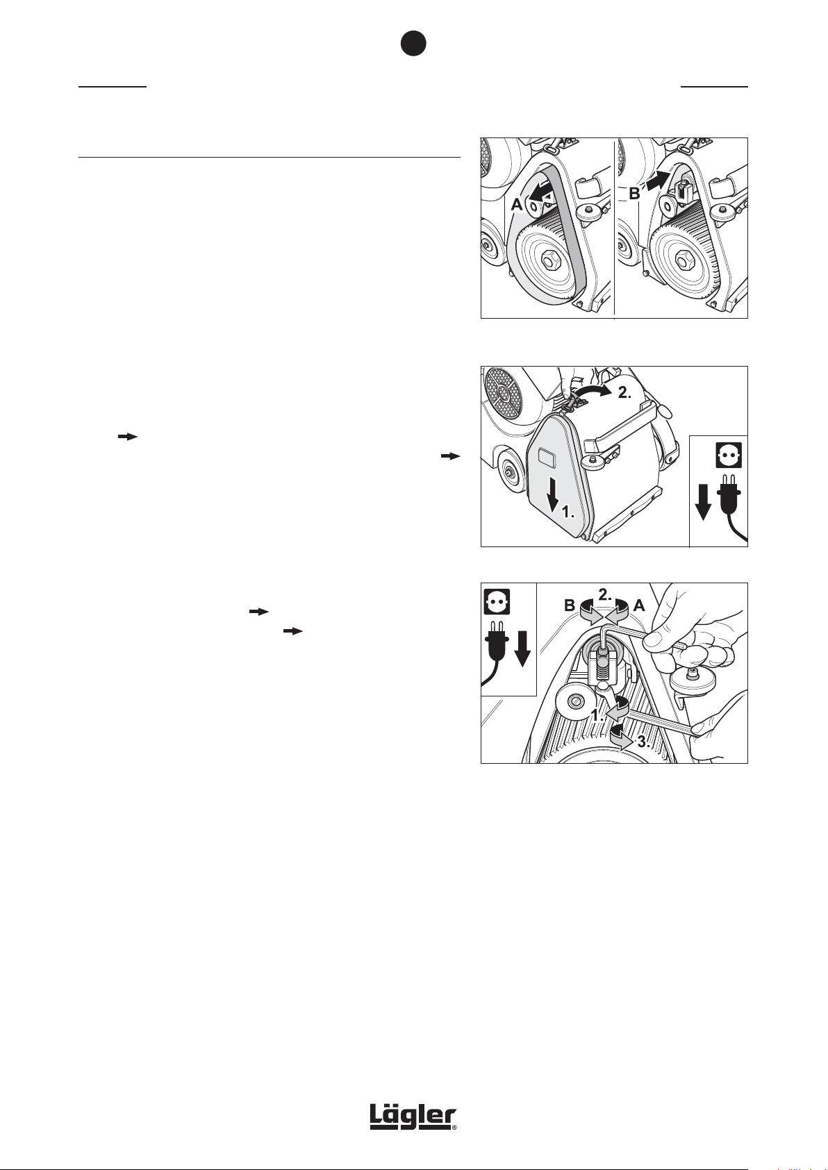
5 If the sanding belt runs to the front (towards A in Fig. 70) or
to the back (towards B in Fig. 70) the setting of the sanding
belt regulation is necessary ( Section 7.3.2, Setting the
sanding belt tracking). If the sanding belt tracking is alright,
mount the side cover (Fig. 71).
HUMMEL® 01.12.2012
English / Englisch
Page 35
7
MAINTENANCE WORK AND REPLACEMENT OF WEARING PARTS
7.3.2 SETTING THE SANDING BELT TRACKING
Should the setting of the sanding belt tracking be necessary,
proceed as follows:
1 Lift the sanding drum off the floor by turning the lowering
lever at the handle upwards (Fig. 66)!
2 Switch off the machine!
3 Release the cover lock (Fig. 67, 1.) and remove the side cover
on the right of the machine housing (Fig. 67, 2.).
4 Check whether any soiling at the tensioning roller calls for
readjustment. If so, the tensioning roller must be cleaned
( Section 7.1.1, Dismantling and cleaning of drive unit)
and the sanding belt tracking must be checked again (
Section 7.3.1, Checking the sanding belt tracking).
5 Always set the sanding belt tracking using a sanding belt with
as fine a grit grade as possible (= flexible sanding belt). This
is because the more flexible the sanding belt, the precisely
it is possible to set the tensioning roller.
Mount the sanding belt ( Section 5.2, Changing the sanding
belt) and carry out a test run ( Section 7.3.1, Checking the
sanding belt tracking).
If the sanding belt is running out of true (in direction of A
or B in Fig. 70), it must be turned around and another test
performed.
Fig. 70 If the sanding belt runs in direction of A or B, the
setting of the sanding belt regulation is necessary.
Fig. 71 Mount the side cover.
If the sanding belt runs to the front (in direction of A in Fig. 70)
and after turning over runs to the back (in direction of B in
Fig. 70) or vice versa, the sanding belt is of poor quality and
is not usable (conical sleeve)!
If the sanding belt runs in the same direction both times, the
tensioning roller requires readjustment.
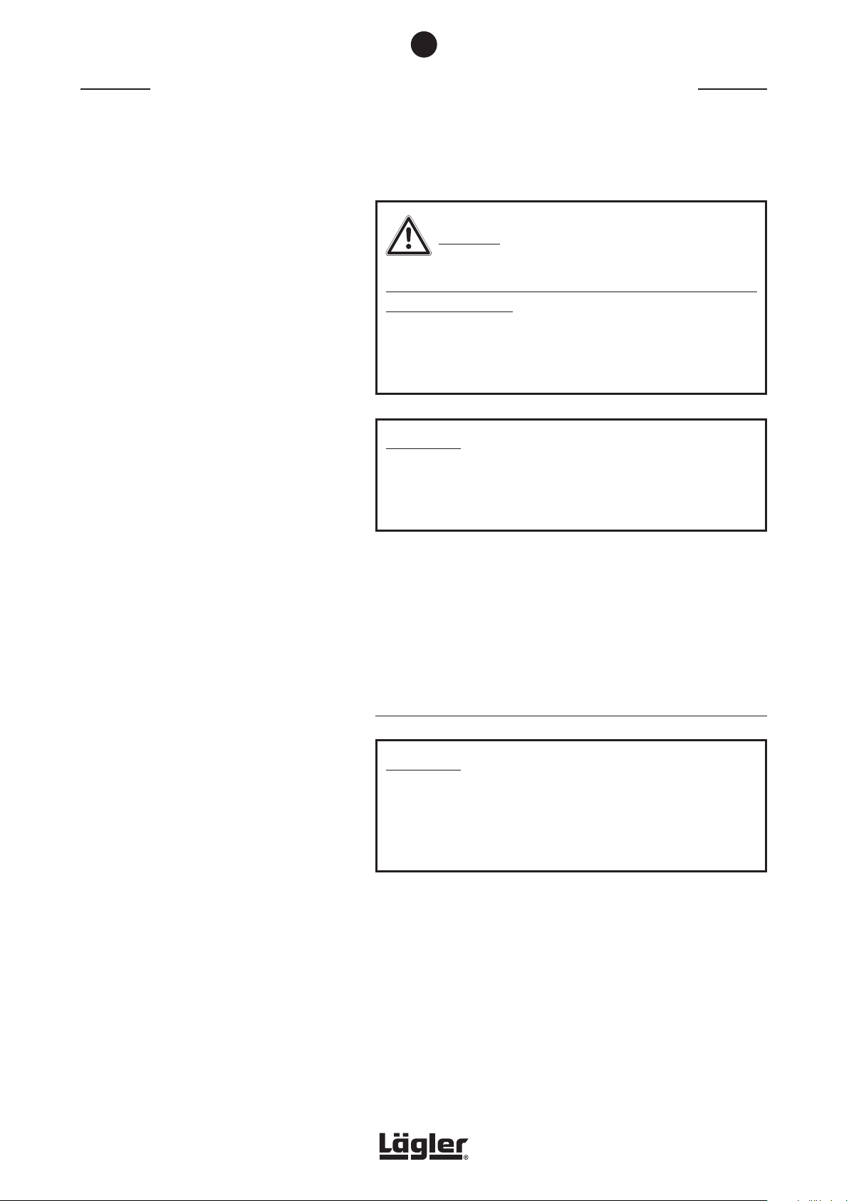
6 If readjustment of the tensioning roller is necessary, release
the lock nut at the drive unit (Fig. 72, 1.) and adjust the
tensioning roller with the screw (Fig. 72, 2.):
A Rotation clockwise:
sanding belt runs to the front
B Rotation counterclockwise:
sanding belt runs to the back
HUMMEL® 01.12.2012
English / Englisch
Fig. 72 Adjust the sanding belt tracking at the setting
screw of the drive unit (see description on the
left).
35
Page 36
7
MAINTENANCE WORK AND REPLACEMENT OF WEARING PARTS
7 If the sanding belt tracking is seen to be correct after adjusting
once, tighten the lock nut again (Fig. 72, 3.).
CAUTION!
RISK OF INJURY and RISK OF PROPERTY DAMAGE from rotating
parts of the machine:
If the lock nut at the upper part of the drive unit is not tightened,
it will loosen during operation of the machine and falls on
rotating parts!
ATTENTION!
If the lock nut at the upper part of the drive unit is not tightened,
the tensioning roller can move out of place! This cause negative
effects to the sanding result!
8 If the sanding belt tracking is seen to be not correct after
adjusting once, repeat the process.
9 After successful setting of the sanding belt tracking mount
the side cover (Fig. 71).
7.4 CHECKING THE MACHINE SETTING
ATTENTION!
The best working result is achieved when the sanding drum
sands centrally! Only with this setting is it possible to avoid the
belt from sanding too deep on one side, resulting in unwanted
sanding marks!
36
From time to time, or as a result of incorrect transportation, it is
possible for the machine to become incorrectly adjusted. Incorrect
adjustment is indicated by one-sided sanding of the sanding drum,
which can lead to sanding tracks and complaints. Correction of
machine setting is performed as follows:
1 Switch off the machine and pull the power plug out of the
socket!
HUMMEL® 01.12.2012
English / Englisch
Page 37
7
MAINTENANCE WORK AND REPLACEMENT OF WEARING PARTS
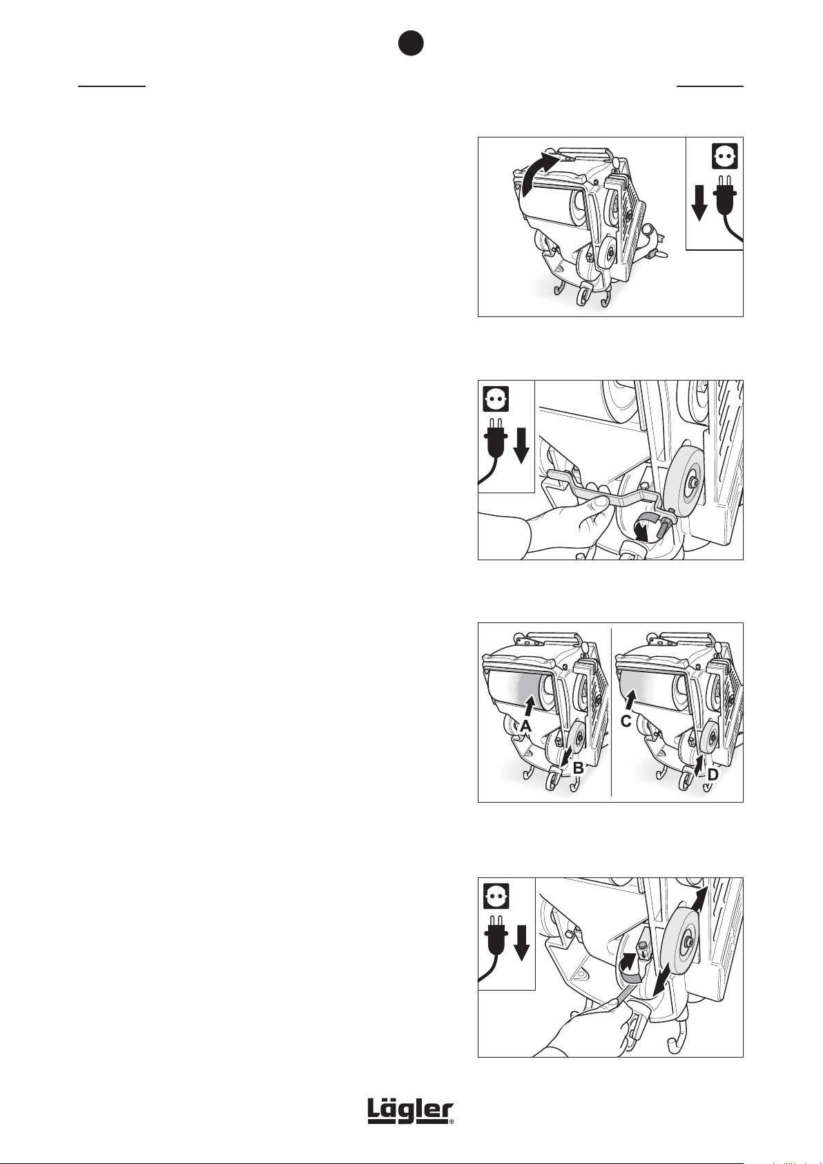
2 Tilt the machine backwards over the safety guards so that you
can see the wheel bearings (Fig. 73). Ensure that the machine
is standing securely!
3 The wheel on the belt guard side can be adjusted by releasing
the tension screw. The other wheel is firmly fixed using a
screw.
4 For setting, first take the actual position of the adjustable
wheel using the setting fixture (right-hand wheel seen from
below). Position the fixture against the machine housing in
such a way that it rests not only against the machine housing
on both sides, but also at the adjustable wheel. If necessary,
turn the threaded pin of the setting device. To do this, release
the nut of the setting fixture (Fig. 74).
Fig. 73 To check the machine setting, tilt the machine
backwards. Ensure that the machine is standing
securely!
5 If the machine is sanding more heavily on the belt guard side
(A in Fig. 75), the wheel must be adjusted away from the belt
guard (direction of B in Fig. 75).
If the machine is sanding more heavily on the side cover side
(C in Fig. 75), the wheel must be adjusted towards the belt
guard (direction of D in Fig. 75).
Now adjust the threaded pin of the setting device in the
relevant direction by the required amount.
6 Release the clamping screw at the wheel clamp of the
adjustable wheel (Fig. 76) and place the setting fixture against
the machine housing again.
7 Set the wheel in the required position by means of the setting
fixture so that the wheel lining just still makes contact with the
threaded pin when turning, and tighten the clamping screw
again.
8 Carry out a sanding test to check whether the machine is
now correctly adjusted. If not, the process will have to be
repeated.
Fig. 74 Take the actual position of the adjustable wheel
using the setting fixture (right-hand wheel seen
from below).
Fig. 75 If the machine is sanding more on side A, the
wheel must be adjusted in the direction of B.
If the machine is sanding more on side C, the
wheel must be adjusted in the direction of D.
HUMMEL® 01.12.2012
English / Englisch
Fig. 76 Release the screw on the right-hand wheel clamp.
37
Page 38
7
MAINTENANCE WORK AND REPLACEMENT OF WEARING PARTS
7.5 CHECKING THE DUST PICK-UP
In order to guarantee optimum dust pick-up for your safety and that
of others, the following points must be observed:
• Always used original LÄGLER® dust bags!
• Never use damaged, washed, patched or in any other way
repaired dust bags!
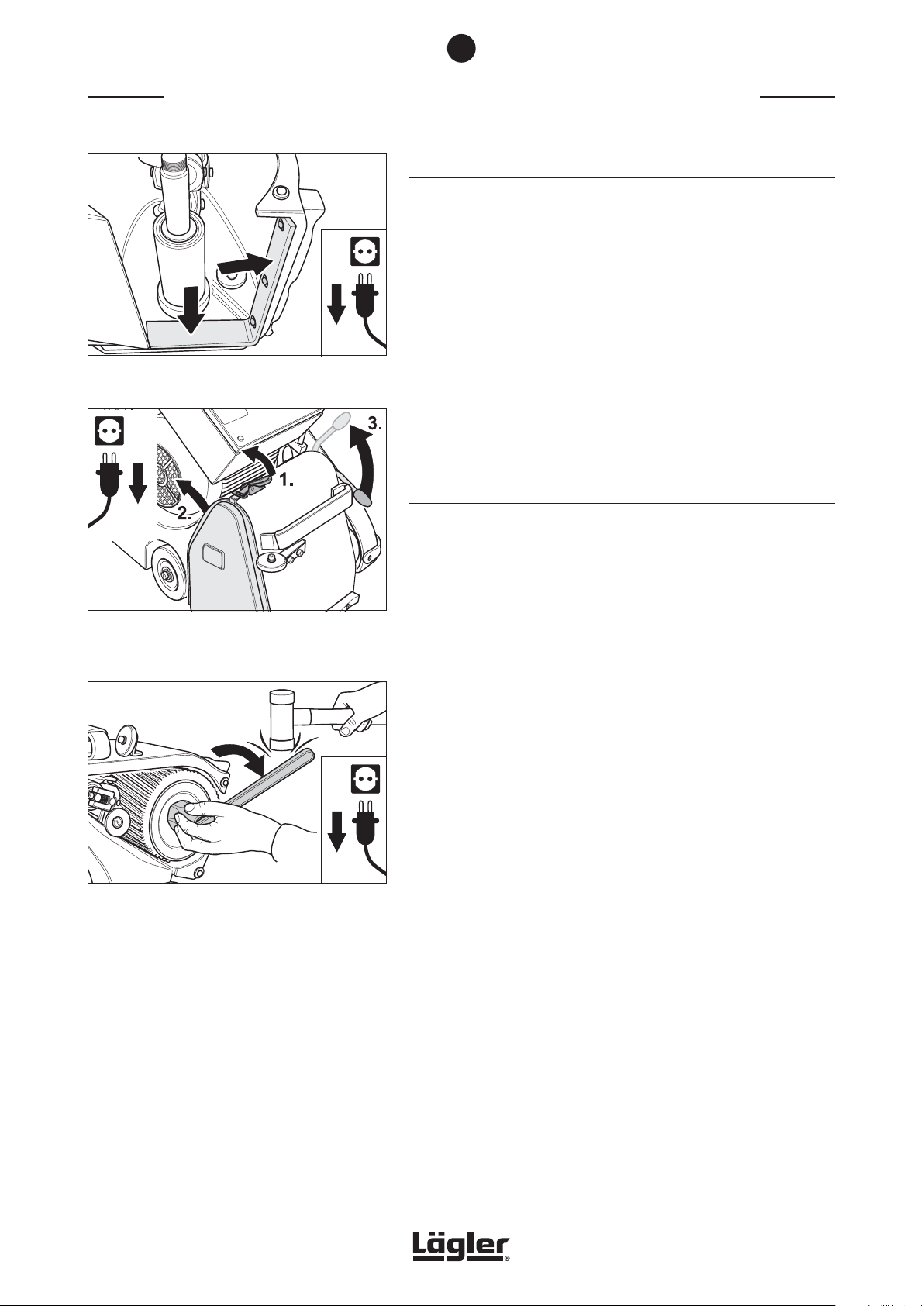
Fig. 77 The sealing felt must not demonstrate any signs
of damage, otherwise replace!
Fig. 78 Release the cover lock (1.), remove the side cover
(2.) and lower the tensioning roller by pulling up
the operating lever (3.).
• Ensure that the sealing felt is not worn or damaged (Fig. 77)!
• Check the suction system for blockages or deposits!
7.6 REPLACEMENT OF SANDING DRUM
Use exclusively original LÄGLER® sanding drums (Part number in
Section 11, Spare parts)!
1 Switch off the machine and pull the power plug out of the
socket!
2 Release the cover lock (Fig. 78, 1.) and remove the side cover
on the right of the machine housing (Fig. 78, 2.).
3 Pull the operating lever of the drive unit upwards (Fig. 78, 3.).
This will lower the tensioning roller.
4 Remove the sanding belt from the tensioning roller and the
sanding drum.
Fig. 79 Release the drum nut clockwise (left-hand
thread), if necessary by knocking gently with a
soft hammer.
Never use a steel hammer!
38
5 Tilt the machine backwards over the safety guards (Fig. 73).
Ensure that the machine is standing securely!
6 Open the drum nut by turning the box wrench (see tool kit)
clockwise (left-hand thread) and unscrew the drum nut
(Fig. 79).
If necessary, take a soft hammer to help you loosen the nut.
Never use a steel hammer!
HUMMEL® 01.12.2012
English / Englisch
Page 39
7
MAINTENANCE WORK AND REPLACEMENT OF WEARING PARTS
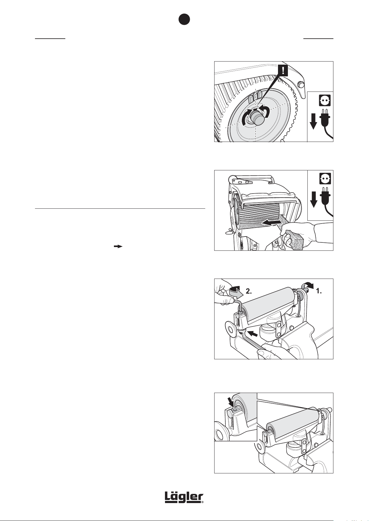
7 Turn the sanding drum in such a way that the groove is pointing
upwards to ensure that the parallel key is not lost (Fig. 80).
Now pull the sanding drum out sideways out of the housing.
If the sanding drum is too stiff to move, use a lath (Fig. 81) to
dislodge it, so as not to damage the machine! Never attempt
to loosen the sanding drum by hitting with a hammer!
8 Clean the shaft stump and oil it slightly.
9 Push on the new sanding drum. Pay attention to the parallel
key!
10 Perform the remaining assembly steps in reverse order.
7.7 REPLACEMENT OF TENSIONING ROLLER
Use exclusively original LÄGLER® tensioning rollers (Part number
in Section 11, Spare parts)!
1 Remove the drive unit ( Section 7.1.1, Dismantling and
cleaning of drive unit).
2 Clamp the drive unit in a vise. If you are unable to reach the
lock nuts with the closed-mouth wrench, screw the lever into
the crank again and turn it downwards (Fig. 82, 1.) so that the
top of the drive unit is lifted up.
3 Remove the two fixing screws in the tensioning roller while
holding onto the locknuts with a closed-mouth wrench
(Fig. 82, 2.).
Fig. 80 Turn the sanding drum in such a way that the
groove is pointing upwards to ensure that the
parallel key is not lost.
Fig. 81 If the sanding drum is too stiff to be removed,
carefully lever it away with a lath.
Never use brute force!
4 Remove the tensioning roller and check the compression
spring. Should this be deformed, the compression spring (Part
number in Section 11, Spare parts) must be renewed.
5 Clean the drive unit. Do not use any cleaning products which
contain solvents!
6 Insert the compression spring and the tensioning roller. Ensure
that the surfaces on the shaft ends of the tensioning roller
are pointing upwards (Fig. 83)!
HUMMEL® 01.12.2012
English / Englisch
Fig. 82 Turn the crank in the indicated direction (1.).
Remove the two fixing screws in the tensioning
roller while holding onto the locknuts with a
closed mouth wrench (2.).
Fig. 83 Insert the new tensioning roller, ensuring that the
surfaces on the shaft ends are pointing upwards!
39
Page 40
7
MAINTENANCE WORK AND REPLACEMENT OF WEARING PARTS
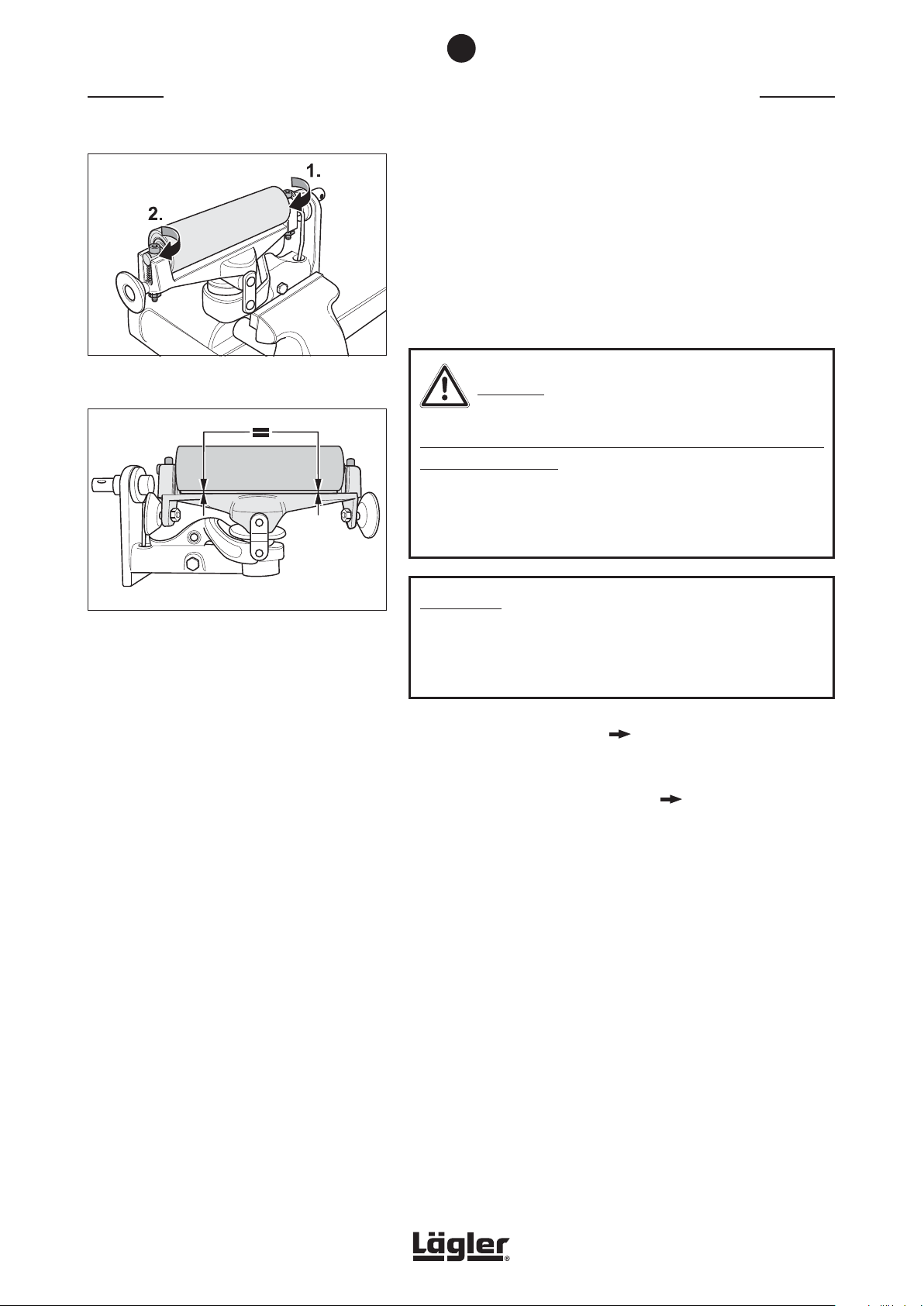
7 Tighten the screw of the unsprung bearing pedestal side
(Fig. 84, 1.).
8 Turn the screw on the sprung side of the tensioning roller
(Fig. 84, 2.) far enough so that the tensioning roller is
positioned parallel to the upper part of the drive unit (Fig. 85).
9 Tighten the lock nuts of the fixing screws!
Fig. 84 Tighten the side without spring (1.) and then the
side with spring (2.), so that …
Fig. 85 … the tensioning roller is positioned parallel to
the top of the drive unit.
CAUTION!
RISK OF INJURY and RISK OF PROPERTY DAMAGE from rotating
parts of the machine:
If the lock nuts of the fixing screws are not tightened, they will
loosen during operation of the machine and fall on rotating
parts!
ATTENTION!
If the lock nuts of the fixing screws are not tightened, the
tensioning roller can move out of place! This cause negative
effects to the sanding result!
10 Remount the drive unit ( Section 7.1.1, Dismantling and
cleaning of drive unit).
11 Check the sanding belt tracking (
Section 7.3.1, Checking
the sanding belt tracking).
40
HUMMEL® 01.12.2012
English / Englisch
Page 41
7
MAINTENANCE WORK AND REPLACEMENT OF WEARING PARTS
7.8 REPLACEMENT OF REAR WHEEL
Use exclusively original LÄGLER® rear wheels (Part number in
Section 11, Spare parts)!
7.8.1 REPLACEMENT OF REAR WHEEL ONLY
1 Switch off the machine and pull the power plug out of the
socket!
2 Tilt the machine forward over the bracket (Fig. 86). Ensure
that the machine is standing securely (Fig. 87)!
3 Release the screw in the centre of the wheel and remove the
screw, washers and nut (Fig. 88). Ensure that you do not lose
the nut.
4 Pull the back wheel off the tail axle housing.
5 Push the new back wheel onto the tail axle housing.
6 Insert the nut in the hexagonal recess of the tail housing and
hold onto the nut. Mount the washers and the screw.
7.8.2 REPLACEMENT OF COMPLETE REAR WHEEL ASSEMBLY
1 Switch off the machine and pull the power plug out of the
socket!
2 Tilt the machine forward over the bracket (Fig. 86). Ensure
that the machine is standing securely (Fig. 87)!
3 Release the screw which fastens the tail axle of the rear
wheel in the machine housing (Fig. 89).
Fig. 86 Pull the power plug out of the socket! Tilt the
machine forward over the bracket.
Fig. 87 Ensure that the machine is standing securely!
4 Pull the complete rear wheel assembly out of the machine
housing (Fig. 89).
5 Mount the complete new back wheel in reverse sequence and
fasten it again in the machine housing, aligning the clamping
surface of the tail axle towards the screw (Fig. 89).
HUMMEL® 01.12.2012
English / Englisch
Fig. 88 Remove the screw with the washers and nut in the
centre of the wheel and take off the back wheel.
Assemble in reverse sequence.
Fig. 89 Release the screw and pull the complete rear
wheel assembly out of the machine housing.
When mounting, align the clamping surface of the
tail axle towards the screw.
41
Page 42
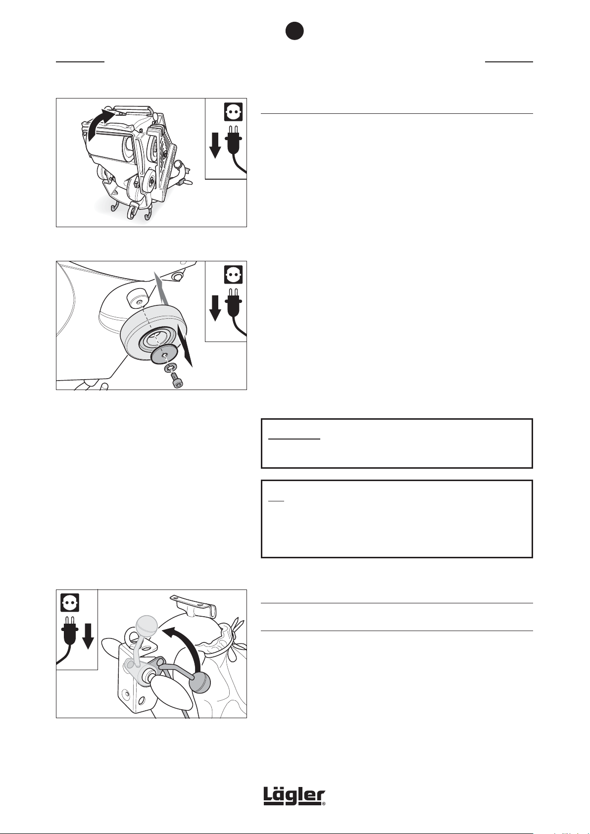
MAINTENANCE WORK AND REPLACEMENT OF WEARING PARTS
Fig. 90 Tilt the machine backwards. Ensure that the
machine is standing securely!
7
7.9 REPLACEMENT OF LATERAL WHEELS
Use exclusively original LÄGLER® lateral wheels (Part number in
Section 11, Spare parts)!
1 Switch off the machine and pull the power plug out of the
socket!
2 Tilt the machine backwards over the safety guards (Fig. 90).
Ensure that the machine is standing securely!
3 Release the screw in the centre of the wheel and remove the
screw and washers (Fig. 91). Before removing the left lateral
wheel open the belt guard (Fig. 94).
4 Pull the wheel off the wheel lever.
Fig. 91 Remove the screw and washers in the centre of
the wheel and remove the lateral wheel. Assemble
the new wheel in reverse sequence.
5 Push the new wheel onto the wheel lever.
6 Mount the washers and the screw.
7 Tighten the screw again.
ATTENTION!
The lateral wheels must always be exchanged in pairs!
TIP:
As it is so easy and quick to exchange the lateral wheels and
the back wheel, it is advisable to use a second set of wheels
when performing rough work.
7.10 REPLACEMENT AND TENSIONING OF V-BELTS
7.10.1 REPLACEMENT OF V-BELTS
Fig. 92 Lift the sanding drum off the floor by turning the
lowering lever at the handle upwards.
42
Use exclusively original LÄGLER® V-belts (Part number in Section 11,
Spare parts)!
1 Switch off the machine and pull the power plug out of the
socket!
2 Lift the sanding drum off the floor by turning the lowering
lever at the handle upwards (Fig. 92).
HUMMEL® 01.12.2012
English / Englisch
Page 43
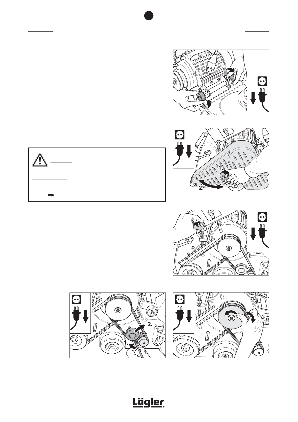
7
MAINTENANCE WORK AND REPLACEMENT OF WEARING PARTS
3 Loosen the two motor nuts at the motor bearing bracket
(Fig. 93).
4 Open the belt guard (Fig. 94).
5 Release the tension of the V-belts by turning the eye bolt at
the motor counterclockwise (Fig. 95).
6 Open the clamping screw of the belt tensioner for the suction
V-belt (Fig. 96, 1.)
7 Turn the belt tensioner clockwise to release the tension of
the suction V-belt (Fig. 96, 2.).
CAUTION!
Fig. 93 Loosen the two motor nuts.
RISK OF INJURY:
During dismantling and mounting the V-belts, take care of your
fingers danger of crushing!
8 Turn the motor pulley and allow the suction V-belt to run off
the motor pulley (Fig. 97).
Fig. 94 Pull the power plug out of the socket and open
the belt guard.
Fig. 95 Release the tension of the V-belts by turning the
eye bolt at the motor counterclockwise.
HUMMEL® 01.12.2012
English / Englisch
Fig. 96 Open the clamping screw of the belt tensioner (1.)
and release the tension of the suction V-belt (2.).
Fig. 97 Remove the suction V-belt.
43
Page 44
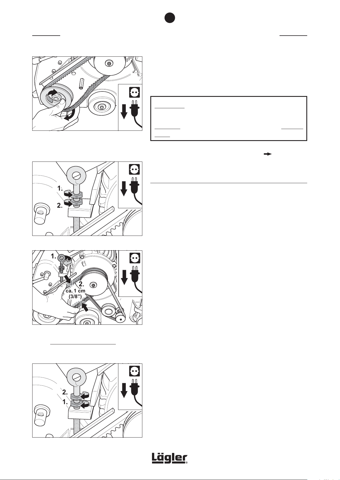
MAINTENANCE WORK AND REPLACEMENT OF WEARING PARTS
Fig. 98 Allow the drive V-belt to run off the lower pulley.
If necessary, use the box wrench (see tool kit) to
help you. Turn the pulley exclusively clockwise
in order not to loosen the nut!
7
9 Turn the lower pulley and allow the drive V-belt to run off the
lower pulley (Fig. 98).
If necessary, use the box wrench (see tool kit) to turn the
lower pulley exclusively clockwise!
ATTENTION!
Only turn the nut with the box wrench at the lower pulley
clockwise, as otherwise the nut will work loose (left-hand
thread)!
10 Mount the new V-belts and tension them ( Section 7.10.2,
Tensioning of V-belts).
7.10.2 TENSIONING OF V-BELTS
Fig. 99 Loosen the two nuts at the eye bolt at the motor.
Fig. 100 Tension the drive V-belt by turning the eye bolt at
the motor clockwise (1.).
Correct tension of the drive V-belt:
The V-belt should be compressed approx. 1 cm
(3/8“) (2.).
In case to retension the V-belts only, point 1 to 4 in Section 7.10.1,
Replacement of V-belts must be done first. Only then proceed as
follows.
1 Open the clamping screw of the belt tensioner for the suction
V-belt (Fig. 96, 1.).
2 Turn the belt tensioner clockwise to release the tension of
the suction V-belt (Fig. 96, 2.).
3 Loosen the two nuts at the eye bolt at the motor (Fig. 99) and
turn them upwards.
4 Tension the drive V-belt for the sanding drum by turning the
eye bolt at the motor clockwise (Fig. 100, 1.).
Correct tension of the drive V-belt:
The slack on the V-belt should be approx. 1 cm (3/8“) if com-
pressed with normal effort (Fig. 100, 2.).
5 First tighten the lower nut (Fig. 101, 1.), then the upper nut
(Fig. 101, 2.) at the eye bolt at the motor.
Fig. 101 First tighten the lower nut (1.), then the upper nut
(2.) at the eye bolt at the motor.
44
HUMMEL® 01.12.2012
English / Englisch
Page 45

7
MAINTENANCE WORK AND REPLACEMENT OF WEARING PARTS
ATTENTION!
Orient the belt tensioner to the fan pulley! Move the belt
tensioner accordingly (Fig. 102)! A wrong orientation from
belt tensioner to fan pulley increase the wearing of fan axle,
pulleys and V-belt extensive (Fig. 103)! Then these parts must
be replaced significant more often!
6 Turn the belt tensioner counterclockwise to tension the suc-
tion V-belt (Fig. 104, 1.). Keep the belt tensioner in position
and tighten the clamping screw at the belt tensioner carefully
at the same time (Fig. 104, 2.).
Correct tension of the suction V-belt:
The slack on the V-belt should be approx. 1 cm (3/8“) if com-
pressed with normal effort (Fig. 104, 3.).
7 Tighten the two motor nuts (Fig. 105).
8 Close the belt guard (Fig. 106).
ATTENTION!
• Never tension the V-belts excessively! This can cause
damage to the V-belts and ball bearings!
• Check the tension of the V-belts after a while! Retension
the V-belts if necessary!
Fig. 102 Orient the belt tensioner to the fan pulley. Move
the belt tensioner accordingly.
Fig. 103 Avoid position A and B of the belt tensioner!
Otherwise the wearing of fan axle, pulleys and
V-belt increase extensive!
HUMMEL® 01.12.2012
English / Englisch
Fig. 105 Tighten the two motor nuts.
Fig. 104 Tension the suction V-belt by turning the belt
tensioner counterclockwise (1. and 2.).
Correct tension of the suction V-belt:
The V-belt should be compressed approx. 1 cm
(3/8“) (3.).
Fig. 106 Close the belt guard.
45
Page 46
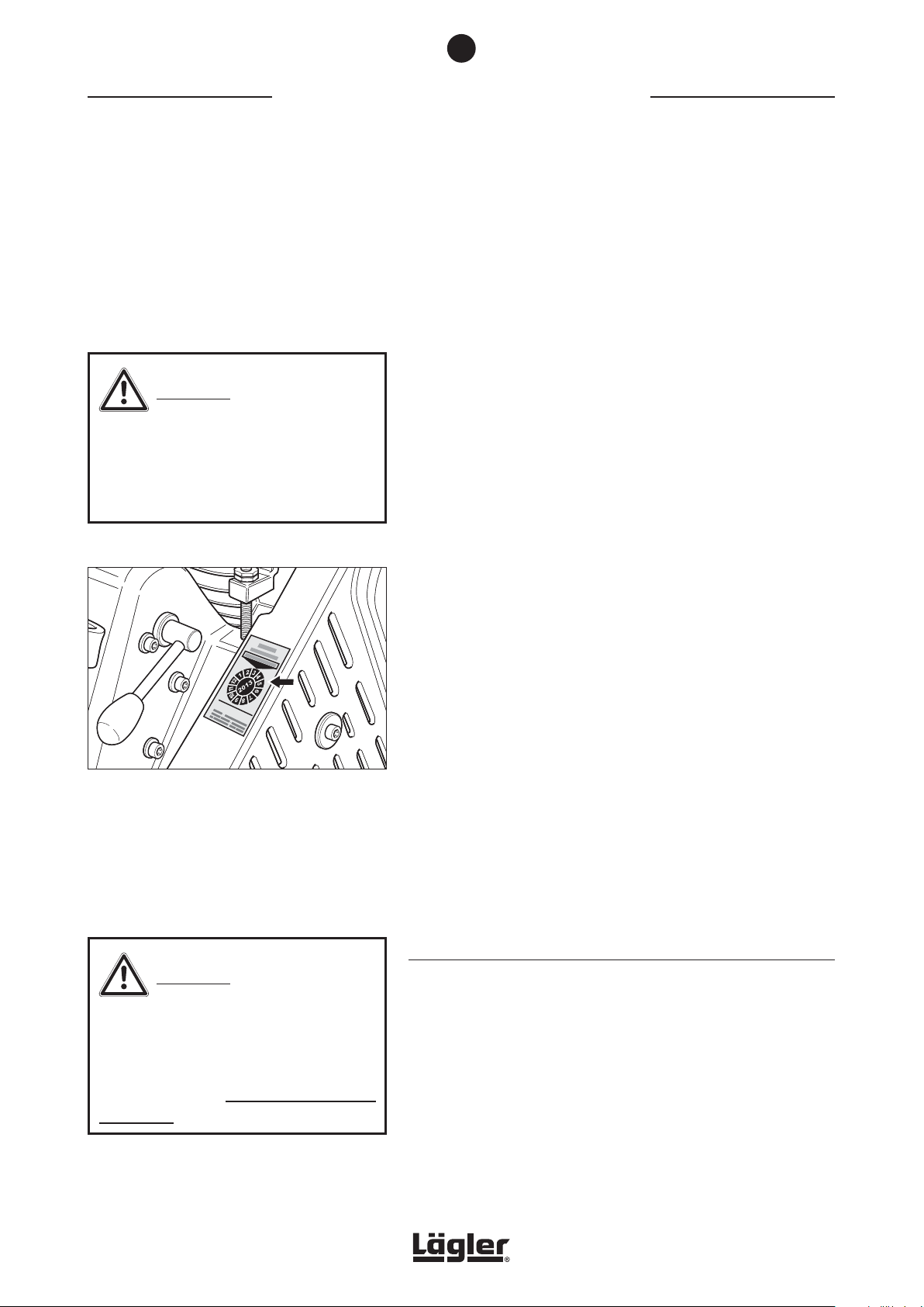
REGULAR MAINTENANCE AND TESTING
Regular maintenance and testing
in accordance with
accident prevention regulations
WARNING!
Tests and testing intervals must comply
with and be performed in accordance
with the applicable regulations and legal
requirements in your country!
8
The electrical operating equipment and machine parts must be
inspected at least once a year by a qualifi ed electrician with respect
to electrical and mechanical safety, then be repaired as required.
Afterwards, the operational safety must be confirmed by the
attachment of an inspection label on the machine (Fig. 107).
The elements required for the dust suction system must be checked
at least once per year by a qualifi ed expert and repaired as required.
The functional efficiency must also be confirmed.
Fig. 107 The inspection label on the belt guard confirms the
electrical and mechanical safety of the machine.
WARNING!
In order to ensure the safety of the machines
and equipment (= working equipment), the
German Ordinance on Industrial Safety and
Health (BetrSichV) must be complied with
in Germany!
Ensure that only original LÄGLER® spare parts are used for
maintenance work! You should only allow the customer service
work to be conducted by LÄGLER® or an authorized LÄGLER®
service centre!
The service passport in these operating instructions (Section 12)
documents when and where your machine was serviced.
Enter the serial number and the year of manufacture of your machine
on the back cover of these operating instructions (please see the
type plate)! If you do not do this, your service passport is invalid!
Make sure that the maintenance tasks in the service passport are
confirmed by filling in a corresponding field with the date, stamp
and signature.
REGULATIONS VALID IN GERMANY
The German Ordinance on Industrial Safety and Health (BetrSichV)
requires every employer to define the testing intervals on the work
equipment they provide according to a risk analysis and to document all of this.
46
HUMMEL® 01.12.2012
English / Englisch
Page 47

8
REGULAR MAINTENANCE AND TESTING
EXCERPT FROM THE BGV A3
§ 5 Inspections
(1) The employer must ensure that the proper condition of the
electrical systems and equipment is inspected
1. before using the equipment for the first time and after an
alteration or repair before being used again by an electrician
or under the supervision of an electrician and
2. at regular intervals.
The intervals are to be calculated in such a manner that defects
which must be handled are detected in a timely manner.
(2) The electrical engineering regulations relevant to the inspection
are to be followed.
(3) Upon request by the professional association, an inspection
log with specific entries is to be maintained.
(4) The inspection before the first commissioning as per paragraph
1 is not required if the employer receives confirmation from the
manufacturer or installer that the electrical systems and equipment have been correspondingly procured in accordance with
these accident prevention guidelines.
NOTE:
• All LÄGLER® machines and electrical
equipment are subjected to an electrical
inspection as well as a thorough visual
and functional test before they leave
the factory.
• A recurring inspection of the machines
and electrical equipment must be
conducted in Germany at certain
intervals.
• LÄGLER® recommends using the
guidelines of BGV A3 for inspections
and inspection intervals.
• You can, of course, arrange for repairs
and recurring inspections of LÄGLER®
machines to be conducted by the
LÄGLER® service department.
Table 1B: Recurring inspections of portable electrical equipment:
Systems/equipment (which are to be inspected)
• portable electrical equipment (insofar as is used)
• extension and device connection cables with plugs
• connection cables with plugs
• movable cables with plugs and fixed connections
Inspection interval
Every 6 months as a reference value, 3 months on construction
sites*).
If an error rate of less than 2% is reached during the inspection,
the inspection interval can be extended to a maximum of 1 year
(valid for machines on construction sites, in production facilities
and workshops).
*) See the BG information “Selection and Operation of Electrical Systems and
Equipment on Construction Sites” (BGI 608) for more details.
Type of inspection
The proper condition of the machines and equipment must be
inspected.
Inspector
Electricians or persons trained in electrical engineering when using
suitable measurement and inspection devices.
HUMMEL® 01.12.2012
English / Englisch
47
Page 48
Causes of faults
WARNING!
RISK OF DEATH from electrical shock:
Work on the electrical equipment is to be
conducted exclusively by a qualified electrician! The machine must be switched
off and the power plug removed from the
socket during this work!
The circuit diagram valid for your machine
is located in the motor switch box!
RISK OF INJURY due to unsuitable parts:
Make sure that only original LÄGLER
spare parts and original LÄGLER® accessories are used!
®
9
CAUSES OF FAULTS
This section shows you how to remedy possible malfunctions. If
none of the measures listed here are successful, please contact
our service department, your retailer or your importer.
THE MACHINE DOES NOT RUN
The machine does not start
• The machine is not connected to the electrical network. Check
the following items:
- Is the motor cable connected to the extension cable?
- Is the extension cable inserted into the power socket?
• The power socket is not properly connected. This error must
be corrected by a professional.
• The electrical safety device of the electrical network interrupted the electrical circuit, e.g. because
- too many electricity consumers are connected to the same
electrical circuit,
- improper electrical installation.
The causes for the error must be repaired by an expert.
• The electrical network is not providing sufficient voltage
(undervoltage). Use a transformer if necessary (e.g. LÄGLER®
part number 708.00.00.100 for 230 volts).
• The temperature switch in the motor has switched off the
machine because
- one or more power cables have a total length of more than
20 m
- the power cables has wire cross-sections which are too
small:
at mains voltage 220 V or 230 V are the wire cross-sections
smaller than 2.5 mm²
at mains voltage 400 V are the wire cross-sections smaller
than 1.5 mm²
- or too much pressure was applied to the sanding drum.
The motor must cool off and the causes for the problems
named above must be remedied.
• An electrical component of the machine (e.g. capacitors,
contactor, cable, switch) is defective and must be inspected
by a qualified electrician and replaced if necessary.
48
HUMMEL® 01.12.2012
English / Englisch
Page 49

9
CAUSES OF FAULTS
The machine attempts to start up but is not able to do so
• At low temperatures: The machine is too cold and must be
heated up to room temperature in a warm room.
• Cables which are too thin or too long are used for the electrical connection:
Power cables with wire cross-sections which are too small
(mains voltage 220 V or 230 V smaller than 2.5 mm², mains
voltage 400 V smaller than 1.5 mm²) or with a total length of
more than 20 m lead to a loss of power and are not allowed
for safety reasons!
• The electrical network is not providing sufficient voltage
(undervoltage). Use a transformer if necessary (e.g. LÄGLER®
part number 708.00.00.100 for 230 volts).
• The V-belts are too tight and must be loosened ( Sec-
tion 7.10, Replacement and tensioning of V-belts).
THE MACHINE RUNS BADLY
The machine runs, but has no or very little sanding power capacity
• The sanding medium is incorrect or dull and must be replaced
( Section 5.2, Changing the sanding belt).
• At low temperatures: The machine is too cold and must be
heated up to room temperature in a warm room.
• Cables which are too thin or too long are used for the electrical connection:
Power cables with wire cross-sections which are too small
(mains voltage 220 V or 230 V smaller than 2.5 mm², mains
voltage 400 V smaller than 1.5 mm²) or with a total length of
more than 20 m lead to a loss of power and are not allowed
for safety reasons!
• The electrical network is not providing sufficient voltage
(undervoltage). Use a transformer if necessary (e.g. LÄGLER®
part number 708.00.00.100 for 230 volts).
• The V-belts are not tight enough and must be tightened a bit
( Section 7.10, Replacement and tensioning of V-belts).
• The sanding pressure do not suit to the grit grade of the sanding belt and must be corrected ( Section 5.3, Regulating
the sanding drum pressure).
HUMMEL® 01.12.2012
English / Englisch
49
Page 50
9
CAUSES OF FAULTS
The machine vibrates intensely and runs noisily
• The sanding medium does not have the proper tension. The
tension must be corrected (
sanding belt).
• The sanding medium is damaged or incorrect and must be
replaced (
• The sanding belt tracking is incorrect and must be adjusted
( Section 7.3, Checking and setting the sanding belt
tracking).
• The sanding drum is dirty or damaged and must be replaced
( Section 7.6, Replacement of sanding drum).
• The tensioning roller of the drive unit is dirty or damaged and
must be replaced ( Section 7.7, Replacement of tensioning
roller).
Section 5.2, Changing the sanding belt).
Section 5.2, Changing the
• A V-belt is dirty, damaged or worn-out and must be replaced
( Section 7.10, Replacement and tensioning of V-belts).
• A pulley is dirty or worn-out and must be cleaned or replaced.
• There are clogged materials and deposits in the machine that
must be removed.
THE MACHINE RUNS BUT CREATES A GREAT DEAL OF DUST
• The dust bag is more than one third full and must be emptied
( Section 5.4, Emptying the dust bag).
• The dust bag is not correctly attached or is damaged and
must be replaced ( Section 4.1, Preparing the machine
for operation).
• The sealing felt at the machine housing is damaged and must
be replaced ( Section 7.5, Checking the dust pick-up).
• The dust suction system is clogged up and must be cleaned.
• The suction V-belt is not tight enough and must be tightened
or damaged and must be replaced ( Section 7.10, Replace-
ment and tensioning of V-belts).
50
• The side cover is not mounted at the machine and must be
mounted ( Fig. 13).
HUMMEL® 01.12.2012
English / Englisch
Page 51

9
CAUSES OF FAULTS
SANDING PROBLEMS
Waves, strips, grooves
• The floor was not vacuumed before sanding. The floor must
always be vacuumed thoroughly before the first and after
each additional sanding operation.
• The sanding drum was not lifted from the floor while the
machine was switched on or off. Always lift the sanding
drum off the floor before switching on or off the machine
( Section 4.3, Switching on the machine and Section 4.4,
Switching off the machine).
• The sanding medium does not have the proper tension. The
tension must be corrected ( Section 5.2, Changing the
sanding belt).
• The sanding medium is damaged or incorrect and must be
replaced ( Section 5.2, Changing the sanding belt).
• The sanding pressure do not suit to the grit grade of the sanding belt and must be corrected ( Section 5.3, Regulating
the sanding drum pressure).
• The machine setting is not correct and must be adjusted. The
sanding drum must sands centrally ( Section 7.4, Checking
the machine setting).
• The sanding drum is dirty or damaged and must be replaced
( Section 7.6, Replacement of sanding drum).
• The tensioning roller of the drive unit is dirty or damaged and
must be replaced ( Section 7.7, Replacement of tensioning
roller).
• The wheels are dirty or damaged and must be cleaned or
replaced ( Section 7.8, Replacement of rear wheel and
Section 7.9, Replacement of lateral wheels).
• A V-belt is dirty, damaged or worn-out and must be replaced
( Section 7.10, Replacement and tensioning of V-belts)
• A pulley is dirty or worn-out and must be cleaned or replaced.
• The lowering rod linkage is running poorly, catching on
something or getting stuck. Free movement is necessary.
• The machine is being moved too slowly and must be sped up.
HUMMEL® 01.12.2012
English / Englisch
51
Page 52

9
CAUSES OF FAULTS
• Too much pressure is placed on the sanding drum while
sanding.
The following causes must be eliminated:
- additional weight is on the machine,
- the rear part of the machine is lifted on with the handle
while sanding,
- the lowering lever at the handle is pressed downwards while
sanding.
52
HUMMEL® 01.12.2012
English / Englisch
Page 53
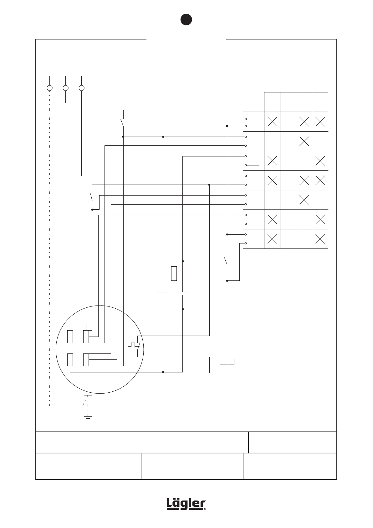
back-up fuse: 16 A
power supply: 230V/50CPS
R1
8.6
kW
selector switch
S1
operation
temperature
switch
M1
motor 2.2 kW
230V/50CPS
start
operation
stop
test
HUMMEL + ELF: single-phase AC motor
®
2,2kW/230V/50CPS
C = starting capacitorA
C = running capacitor
Ha = main winding
Hi = auxiliary winding
B
Phone: 0049 - 7135 - 98 90 - 0
Fax: 0049 - 7135 - 98 90 - 98
e-mail: [email protected]
Internet: http://www.laegler.com
N
K1M
4
3
PE
L1
N
1
2
L1
K1M
6
5
R
01
22
C1
1
N
02
2
11
A
A
4
3
2
1
K1M
C
B
40 Fm
CA
60 Fm
K1M
A1
A2
4
3
2
1
Hi
Hi
Ha
Ha
1~
02.03.1999
EUGEN LÄGLER GMBH
Kappelrain 2
D-74363 Güglingen-Frauenzimmern
10
CIRCUIT DIAGRAMS
The circuit diagram valid for your machine is located in the motor switch box.
HUMMEL® 01.12.2012
English / Englisch
53
Page 54
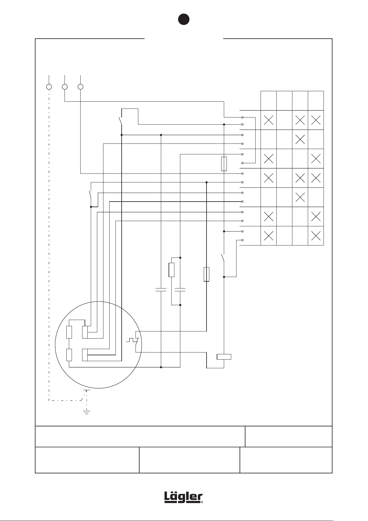
N
K1M
4
3
PE
L1
N
1
2
L1
K1M
6
5
R
01
22
C1
1
N
02
2
11
A
A
4
3
2
1
K1M
C
B
40 Fm
CA
60 Fm
K1M
A1
A2
4
3
2
1
Hi
Hi
Ha
Ha
1~
17.12.2009
EUGEN LÄGLER GMBH
Kappelrain 2
D-74363 Güglingen-Frauenzimmern
back-up fuse: 20 A
power supply: 220 + 230V/60CPS
R1
8.6
kW
selector switch
S1
operation
temperature
switch
M1
motor 2.2 kW
220+230V/60CPS
start
operation
stop
test
fuse
6.2 A
fuse
6.2 A
HUMMEL + ELF: single-phase AC motor
®
2.2kW/220V/60CPS
2.2kW/230V/60CPS
C = starting capacitorA
C = running capacitor
Ha = main winding
Hi = auxiliary winding
B
e-mail: [email protected]
Internet: http://www.laegler.com
Phone: 0049 - 7135 - 98 90 - 0
Fax: 0049 - 7135 - 98 90 - 98
10
CIRCUIT DIAGRAMS
The circuit diagram valid for your machine is located in the motor switch box.
54
HUMMEL® 01.12.2012
English / Englisch
Page 55
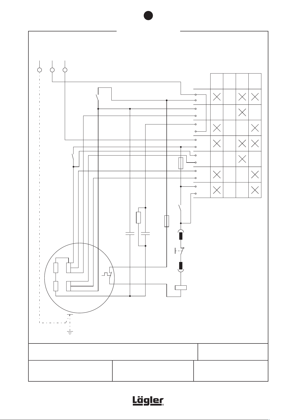
N
K1M
4
3
PE
L1
N
1
2
L1
K1M
6
5
R
01
22
C1
1
N
02
2
11
A
A
3
4
1
2
K1M
C
B
40 Fm
CA
130 Fm
K1M
A1
A2
4
3
2
1
Hi
Hi
Ha
Ha
1~
02.03.1999
S0
EUGEN LÄGLER GMBH
Kappelrain 2
D-74363 Güglingen-Frauenzimmern
back-up fuse: 20 A
power supply: 220V/60CPS
R1
8.6
kW
selector switch
S1
operation
temperature
switch
M1
motor 2.9 kW
220V/60CPS
USA version
start
operation
stop
test
fuse
6.2 A
fuse
6.2 A
HUMMEL + ELF: single-phase AC motor
®
2.9kW/220V/60CPS
USA version
C = starting capacitorA
C = running capacitor
Ha = main winding
Hi = auxiliary winding
S0 = emergency switch
B
e-mail: [email protected]
Internet: http://www.laegler.com
Phone: 0049 - 7135 - 98 90 - 0
Fax: 0049 - 7135 - 98 90 - 98
10
CIRCUIT DIAGRAMS
The circuit diagram valid for your machine is located in the motor switch box.
HUMMEL® 01.12.2012
English / Englisch
55
Page 56
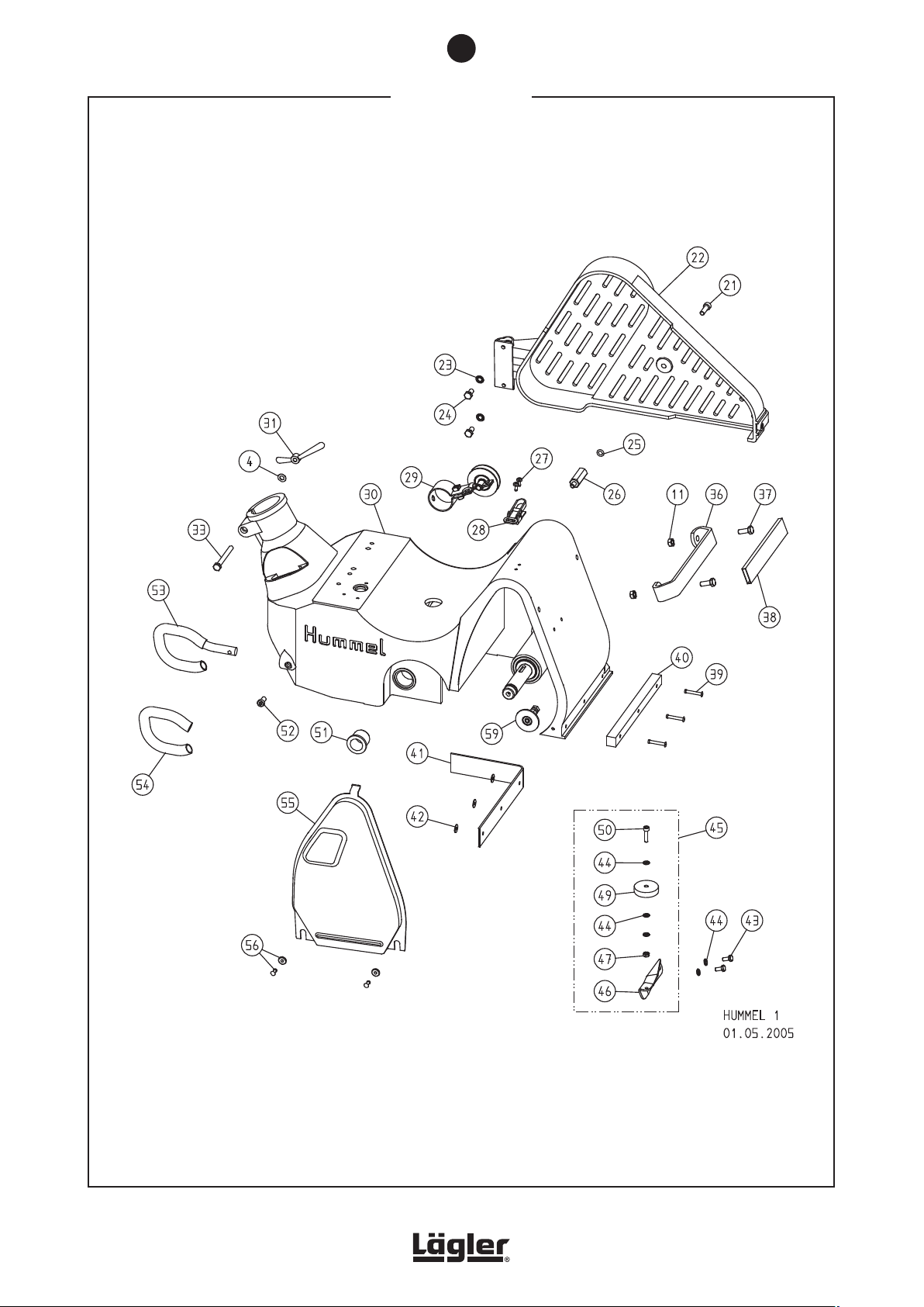
11
SPARE PARTS
56
HUMMEL® 01.12.2012
English / Englisch
Page 57

11
SPARE PARTS
Item Part number Description
4 0125.1008.000 Washer
11 0980.1008.000 Nut
21 0912.1008.025 Screw
22 100.50.00.100 Belt guard, complete
23 6797.1008.000 Washer
24 0933.1008.016 Screw
25 000.01.40.001 O-ring
26 100.50.04.105 Screw stud
27 7500.1005.012 Screw
28 100.01.05.105 Cover fastener
29 100.58.00.200 Belt tensioner, complete
30 100.01.00.100 Housing
31 000.20.45.083 Wing nut
33 0931.1008.075 Screw
36 100.33.01.100 Bracket
37 0933.1008.022 Screw
38 100.33.02.100 Grip
39 7337.1005.033 Rivet
40 100.01.01.100 Bumper felt
41 100.01.02.100 Sealing felt
42 9021.1005.000 Washer
43 0933.1006.014 Screw
44 0125.1006.000 Washer
45 100.60.00.200 Wall-protecting roller with holder
46 100.60.01.100 Holder for wall-protecting roller
47 0934.1006.000 Nut
49 100.60.02.200 Wall-protecting roller
50 0912.1006.030 Screw
51 000.43.10.252 Plastic bushing
52 7984.1008.016 Screw
53 100.44.00.100 Safety guard, complete
54 100.44.01.100 PVC tube
55 100.01.03.100 Side cover
56 100.01.08.200 Collar nut, complete
59 100.01.30.100 Guide roller, complete
HUMMEL® 01.12.2012
English / Englisch
57
Page 58
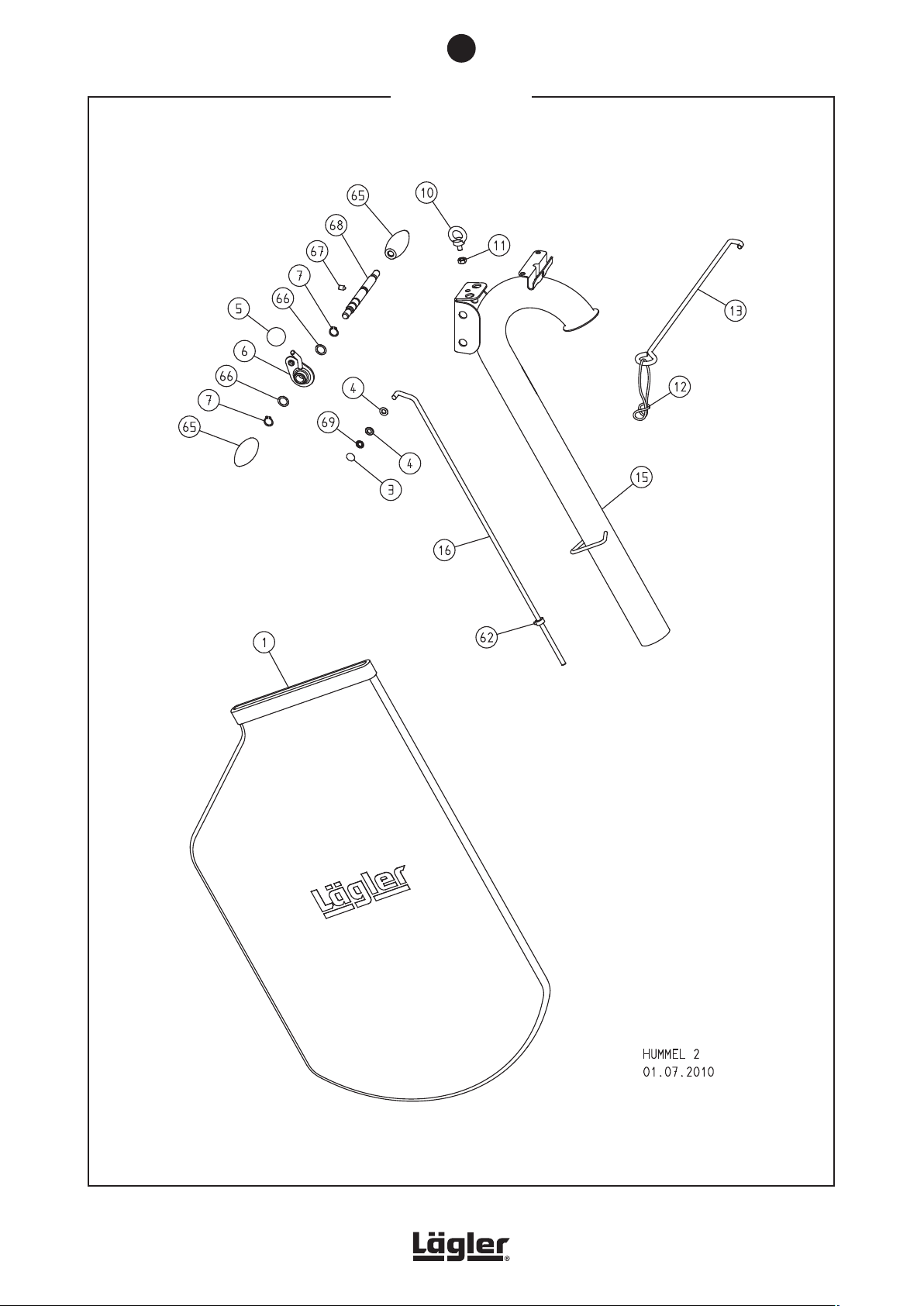
11
SPARE PARTS
58
HUMMEL® 01.12.2012
English / Englisch
Page 59
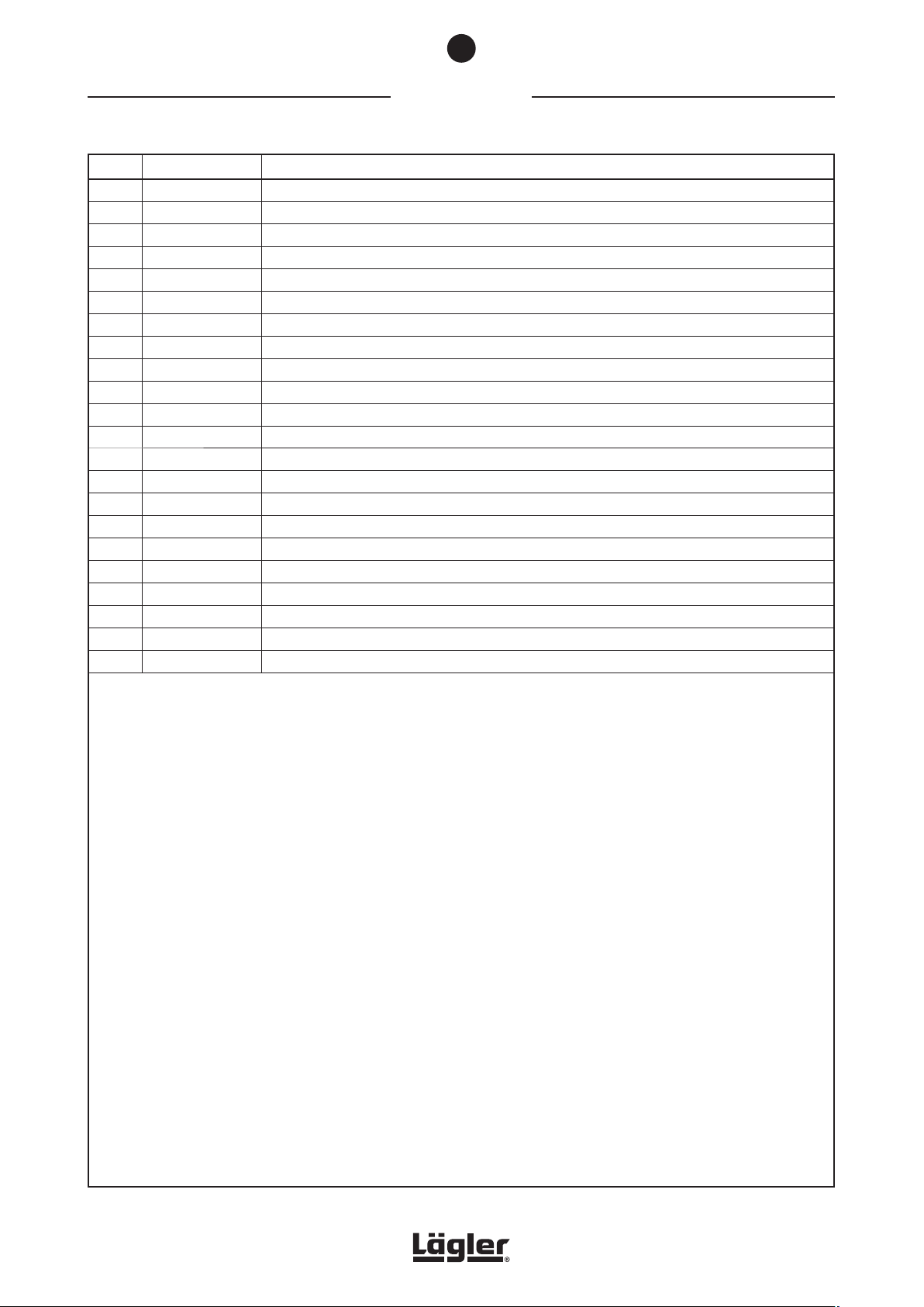
SPARE PARTS
Item Part number Description
1 100.00.80.105 Dust bag HUMMEL
3 000.17.21.081 Fixing cap
4 0125.1008.000 Washer
5 000.20.56.351 Ball knob
6 100.20.18.200 Lever
7 0471.0015.000 Circlip
10 0580.1008.000 Thread eye
11 0980.1008.000 Nut
12 00.000.41.002 Strain relief ring
13 100.20.26.100 Cable support, complete
15 100.20.01.200 Guide tube
102.20.01.200 Guide tube USA
100.20.00.200 Guide tube, complete
102.20.00.200 Guide tube USA, complete
100.21.00.200 Guide tube long, complete
16 100.20.24.100 Upper rod, complete
62 100.20.23.200 Adjusting ring, complete
65 000.20.31.351 Handle
66 0988.0015.005 Washer
67 0914.0008.012 Grub screw
68 100.20.17.200 Axle for handle
69 000.17.20.081 Quick-fixing-fastener
®
11
HUMMEL® 01.12.2012
English / Englisch
59
Page 60
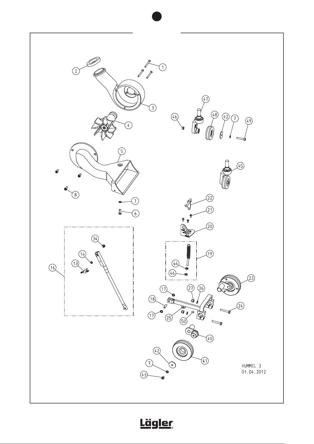
11
SPARE PARTS
60
HUMMEL® 01.12.2012
English / Englisch
Page 61

11
SPARE PARTS
Item Part number Description
1 0965.1006.870 Screw
2 100.08.01.200 Sealing ring
3 100.08.00.100 Fan housing
4 100.10.00.200 Fan insert, complete
5 100.14.00.100 Intake duct
6 0933.1008.022 Screw
7 6797.1008.000 Washer
8 0912.1008.018 Screw
13 000.20.46.062 Wing screw
14 0125.1006.000 Washer
16 100.04.09.100 Lower rod, complete
17 000.17.20.081 Quick-fixing-fastener
18 100.04.01.200 Pivot pin
19 100.04.25.100 Spring with screw, complete
20 100.04.06.200 Notch plate
21 7500.1005.012 Screw
22 100.04.02.100 Spring tensioner, complete
23 100.05.00.200 Lateral wheel, complete
24 0931.1008.050 Screw
25 100.04.00.100 Lifting fixture
26 0125.1008.000 Washer
27 6330.1008.000 Nut
34 000.50.12.061 Nut
40 100.05.04.200 Wheel arm
41 100.05.29.100 Lateral wheel
42 000.10.10.085 Washer
43 7984.1008.012 Screw
45 100.18.00.300 Rear wheel, complete
46 0934.1008.000 Nut
47 100.18.18.300 Tail axle housing, complete
48 100.18.29.105 Rear wheel (from year of manufacture 2002)
100.18.09.200 Rear wheel (up to year of manufacture 2001)
49 0912.1008.040 Screw
50 0914.0008.012 Grub screw
HUMMEL® 01.12.2012
English / Englisch
61
Page 62
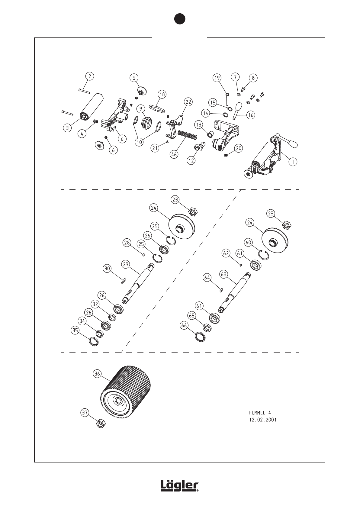
11
SPARE PARTS
up to May 2000
from May 2000
Please state the machine number with
each order!
62
HUMMEL® 01.12.2012
English / Englisch
Page 63

11
SPARE PARTS
Item Part number Description
1 100.45.00.100 Drive unit, complete
2 0912.1006.050 Screw
3 100.45.12.105 Tensioning roller
4 000.31.13.021 Pressure spring
5 100.45.01.105 Guide roller
6 0980.1006.000 Nut
7 0125.1008.000 Washer
8 0912.1008.018 Screw
9 100.45.81.105 Collar
10 000.61.10.363 Cable tie
12 100.45.20.100 Crank
13 100.45.24.105 Bearing bush
14 0988.0018.005 Washer
15 0471.0018.000 Circlip
16 000.20.32.104 Operating lever
18 100.45.17.100 Clip
19 0931.1008.060 Screw
20 0980.1008.000 Nut
21 100.45.61.205 Screw
22 100.45.37.100 Double arm, complete
23 100.02.05.100 Nut, right-hand thread
24 100.36.00.100 V-belt pulley
25 0472.0047.000 Circlip
26 6005.0025.205 Ball bearing
28 6885.0606.018 Parallel key
29 100.02.01.100 Sanding shaft
30 6885.0606.040 Parallel key
32 100.02.04.105 Spacer ring
34 100.02.03.105 Slide ring
35 000.11.35.102 Shaft seal
36 120.40.00.100 Sanding drum HUMMEL
120.41.00.100 Sanding drum HUMMEL®, hard rubber cover
37 100.02.06.100 Nut, left-hand thread
46 100.45.45.100 Pressure spring
60 0472.0052.000 Circlip
61 6205.0025.205 Ball bearing
62 6885.0606.010 Parallel key
63 100.02.01.200 Sanding shaft
64 6885.0606.025 Parallel key
65 100.02.03.200 Spacer ring
66 000.11.40.102 Shaft seal
®
HUMMEL® 01.12.2012
English / Englisch
63
Page 64
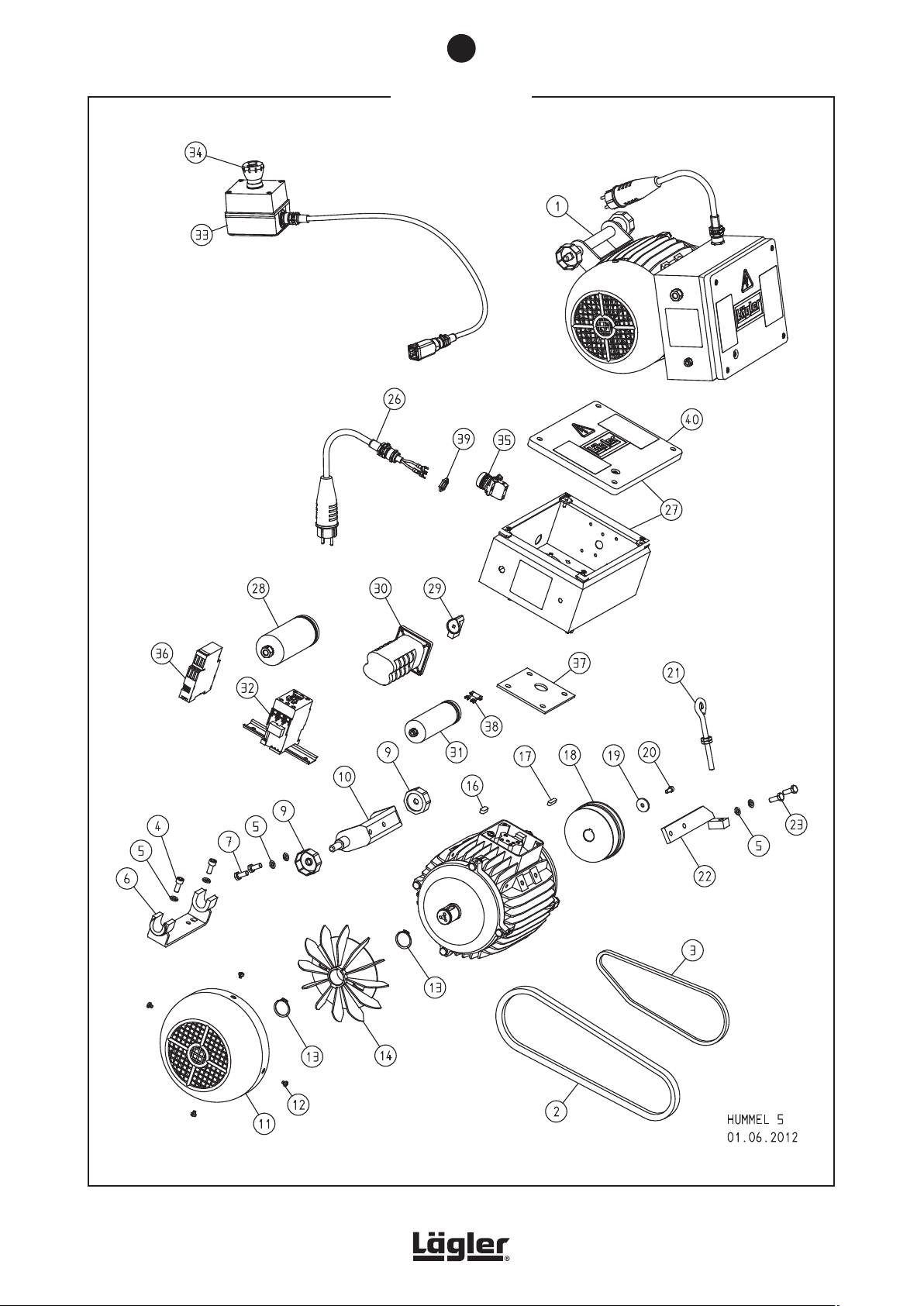
11
SPARE PARTS
64
HUMMEL® 01.12.2012
English / Englisch
Page 65

11
SPARE PARTS
Item Part number Description
1 100.65.00.100 Motor, 230 V / 50 CPS / 2.2 kW
101.65.00.100 Motor, 230 V / 60 CPS / 2.2 kW
102.65.00.100 Motor, 220 V / 60 CPS / 2.9 kW, USA
105.65.00.100 Motor, 400 V / 50 CPS / 4.0 kW, three-phase current
2 000.70.17.092 V-belt
3 000.70.10.067 V-belt
4 0912.1008.020 Screw
5 0127.1008.000 Spring washer
6 100.65.29.200 Motor bearing bracket
7 0933.1008.020 Screw
9 100.65.30.100 Motor nut
10 100.65.25.100 Motor mounting
11 100.65.09.100 Fan cover
12 7500.1005.006 Screw
13 0471.0030.000 Circlip
14 100.65.08.105 Fan wheel
16 6885.0807.020 Parallel key
17 6885.0606.025 Parallel key
18 100.65.06.100 Motor pulley
19 000.10.10.061 Washer
20 0912.1006.014 Screw
21 100.65.80.205 Eye bolt
22 100.65.35.100 Motor tensioner
23 0933.1008.022 Screw
26 100.65.75.100 Motor cable 3 x 2.5 mm² (from year of manufacture 2008)
000.65.43.251 Motor cable 3 x 2.5 mm² (up to year of manufacture 2007)
102.65.75.100 Motor cable 3 x 2.5 mm², USA (from year of manufacture 2008)
000.65.43.257 Motor cable 3 x 2.5 mm², USA (up to year of manufacture 2007)
105.65.75.100 Motor cable 5 x 1.5 mm² for three-phase AC motor (from year of manufacture 2008)
000.65.45.151 Motor cable 5 x 1.5 mm² for three-phase AC motor (up to year of manufacture 2007)
27 100.65.40.200 Switch box, 230 V / 50 CPS
102.65.40.200 Switch box, 220-230 V / 60 CPS + three-phase current
28 000.65.10.041 Running capacitor 40 µF
29 000.65.62.211 Switch button
30 000.65.60.253 Switch
000.65.60.401 Switch for three-phase AC motor
31 000.65.10.061 Starting capacitor 60 µF
000.65.10.131 Starting capacitor 130 µF, USA
32 000.65.20.035 Contactor
000.65.20.032 Contactor complete for three-phase AC motor
33 102.65.60.200 Emergency switch USA, complete
34 000.65.62.221 Red button for emergency switch USA
35 000.65.25.020 Lamp red for three-phase AC motor
36 000.65.20.220 Relay for three-phase AC motor
37 100.65.14.105 Sealing plate
38 000.65.12.091 Discharging resistor
39 000.68.60.207 Nut (from year of manufacture 2008)
000.68.60.163 Nut (up to year of manufacture 2007)
40 100.65.47.100 Cover with seal
HUMMEL® 01.12.2012
English / Englisch
65
Page 66
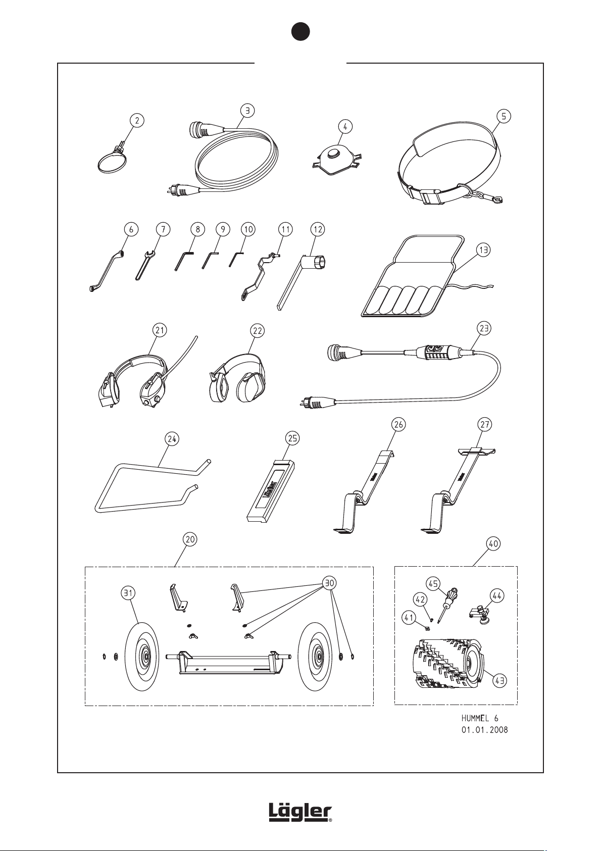
11
SPARE PARTS
66
HUMMEL® 01.12.2012
English / Englisch
Page 67
11
SPARE PARTS
Item Part number Description
2 000.01.40.110 MultiClip
3 000.65.53.251 Extension cable 3 x 2.5 mm², 10 m long
000.65.53.252 Extension cable 3 x 2.5 mm², 20 m long
000.65.55.151 Extension cable 5 x 1.5 mm², 10 m long, for three-phase AC motor
4 000.01.20.010 Respiratory protection mask P3
5 000.01.50.010 Safety belt
6 000.95.21.103 Closed mouth wrench 10/13 mm
7 000.95.11.171 Open mouth wrench 17 mm
8 000.93.11.061 Hexagonal socket screw wrench 6 mm
9 000.93.11.051 Hexagonal socket screw wrench 5 mm
10 000.93.11.041 Hexagonal socket screw wrench 4 mm
11 100.00.50.100 Setting fixture
12 100.00.45.105 Box wrench
13 000.01.30.011 Tool bag, empty
100.98.00.100 Tool bag, complete
20 720.00.00.200 Trolley TRANSCART, complete
21 000.01.10.011 Foldable earmuff type MUSIMUFF with FM radio
22 000.01.10.021 Foldable earmuff type POCKET
23 000.01.65.020 Safety switch PRCD-S (for German mains supply)
24 100.00.55.100 Carrying handle HUMMEL
25 701.10.00.100 Impact tool
26 702.00.00.200 Parquet layer tool ZUGEISEN, small
27 703.00.00.200 Parquet layer tool ZUGEISEN, broad
30 720.10.00.200 Accessories TRANSCART
31 720.05.00.205 Wheel TRANSCART
40 000.10.42.240 Milling drum 200 mm width, complete with accessories
41 900.02.45.105 Carbide tool (10 pcs. per box)
42 900.02.47.105 Screw for blade
43 000.10.42.241 Milling drum with carbide blades
44 000.10.42.243 Cutting depth adjustment, complete
45 000.91.30.151 Torx screwdriver T15
®
HUMMEL® 01.12.2012
English / Englisch
67
Page 68

NOTES
68
HUMMEL® 01.12.2012
English / Englisch
Page 69

NOTES
HUMMEL® 01.12.2012
English / Englisch
69
Page 70

NOTES
70
HUMMEL® 01.12.2012
English / Englisch
Page 71

12
SERVICE PASSPORT
Service passport
Please enter the serial number and the year of manufacture of your machine on the rear side of these operating
instructions (see type plate)! Otherwise the service passport will not be valid!
This service passport is a document. Make sure that all the tests and maintenance work carried out on the machine
are confirmed by the servicing company here.
Date of test and
maintenance work:
Signature and company stamp
Date of test and
maintenance work:
Signature and company stamp
Date of test and
maintenance work:
Date of test and
maintenance work:
Signature and company stamp
Date of test and
maintenance work:
Signature and company stamp
Date of test and
maintenance work:
Date of test and
maintenance work:
Signature and company stamp
Date of test and
maintenance work:
Signature and company stamp
Date of test and
maintenance work:
Signature and company stamp
Date of test and
maintenance work:
Signature and company stamp
Date of test and
maintenance work:
Signature and company stamp
HUMMEL® 01.12.2012
English / Englisch
Signature and company stamp
Date of test and
maintenance work:
Signature and company stamp
Date of test and
maintenance work:
Signature and company stamp
Signature and company stamp
Date of test and
maintenance work:
Signature and company stamp
Date of test and
maintenance work:
Signature and company stamp
71
Page 72
13
EU DECLARATION OF CONFORMITY
EU Declaration of conformity
for machines (EU Directive 2006/42/EC)
The manufacturer Eugen Lägler GmbH, Kappelrain 2, D-74363 Güglingen-Frauenzimmern
Tel.: 0049 - 7135 - 98 90-0 · Fax: 0049 - 7135 - 98 90-98
E-Mail: [email protected] · http://www.laegler.com
certified herewith, that the machine Generic denomination: Floor sanding machine
Function: Dry sanding of wooden floors
Model: HUMMEL
Serial number: See type plate
Commercial name: Belt sanding machine
®
fulfils all the relevant provisions of the specified above European Directive.
The machine also fulfils all the relevant provisions of the European Directive
Electromagnetic compatibility (2004/108/EG).
The following harmonized standards have been applied:
DIN EN ISO 12100: Safety of machinery - General principles for design - Risk assessment and risk reduction
DIN EN 60204-1: Safety of machinery - Electrical equipment of machines - Part 1
DIN EN 55014-1: Electromagnetic compatibility - Requirements for household appliances, electric tools and similar
– 10 / December 1, 2012 – Printed on chlorine-free bleached paper. Part number 00.100.20.002
®
DIN EN 55014-2: Electromagnetic compatibility - Requirements for household appliances, electric tools and similar
DIN EN 61000-3-2: Electromagnetic compatibility (EMC) - Part 3-2: Limits
DIN EN 61000-3-3: Electromagnetic compatibility (EMC) - Part 3-3: Limits
apparatus - Part 1
apparatus - Part 2
Güglingen-Frauenzimmern, December 1, 2012
Dipl.-Ing. (FH) Volker Wörner, Design Engineer
Person Responsible for Documents
Eugen Lägler GmbH, Kappelrain 2
D-74363 Güglingen-Frauenzimmern
HUMMEL
®
Serial number: Year of manufacture:
No guarantee is provided for the contents of these operating instructions. No liability is assumed for errors or damages which arise from the use of these operating instructions. Subject to changes.
Copyright © Eugen Lägler GmbH, 2012 – All rights reserved – Translation of original operating instructions HUMMEL
72
 Loading...