

Page 1
Handling,
Maintenance, Safety
Operating instructions of the edge-, corner- and stair-sanding machine
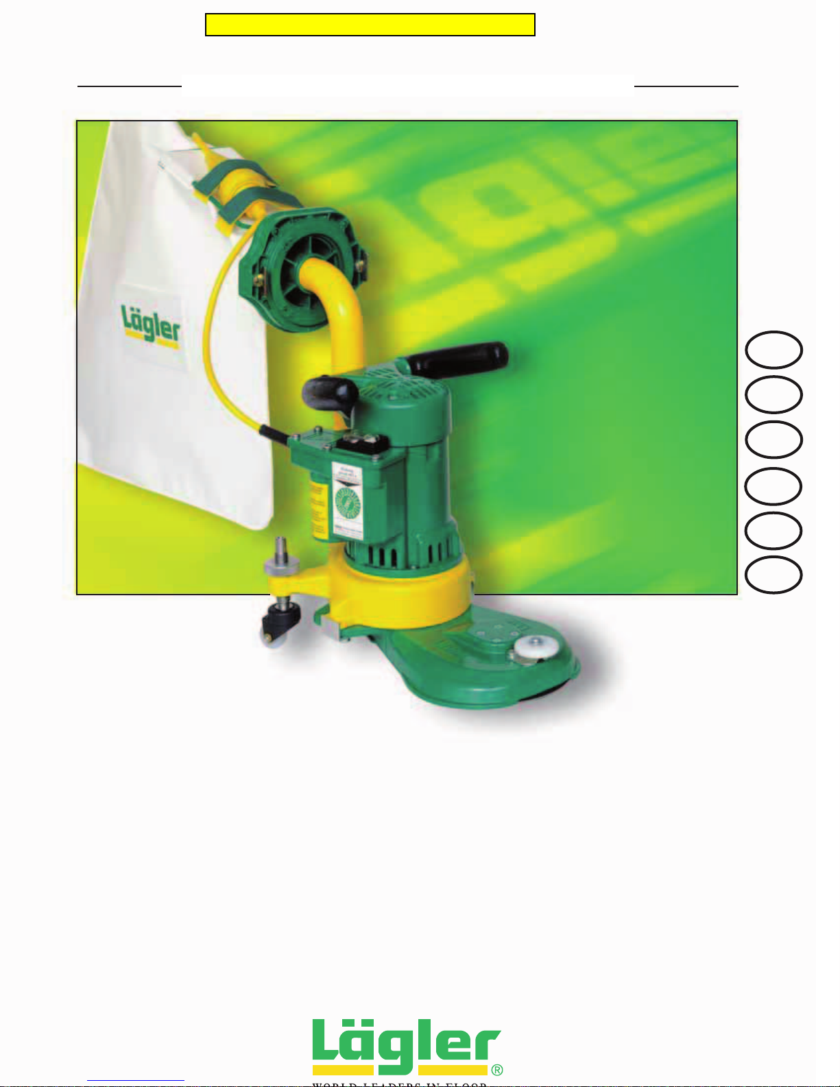
EDGE-, CORNER- AND STAIR-SANDING MACHINE FLIP
FLIP
CAN
GB
NZ
USA
AUS
IRL
Pricing in this catalog is outdated
Page 2
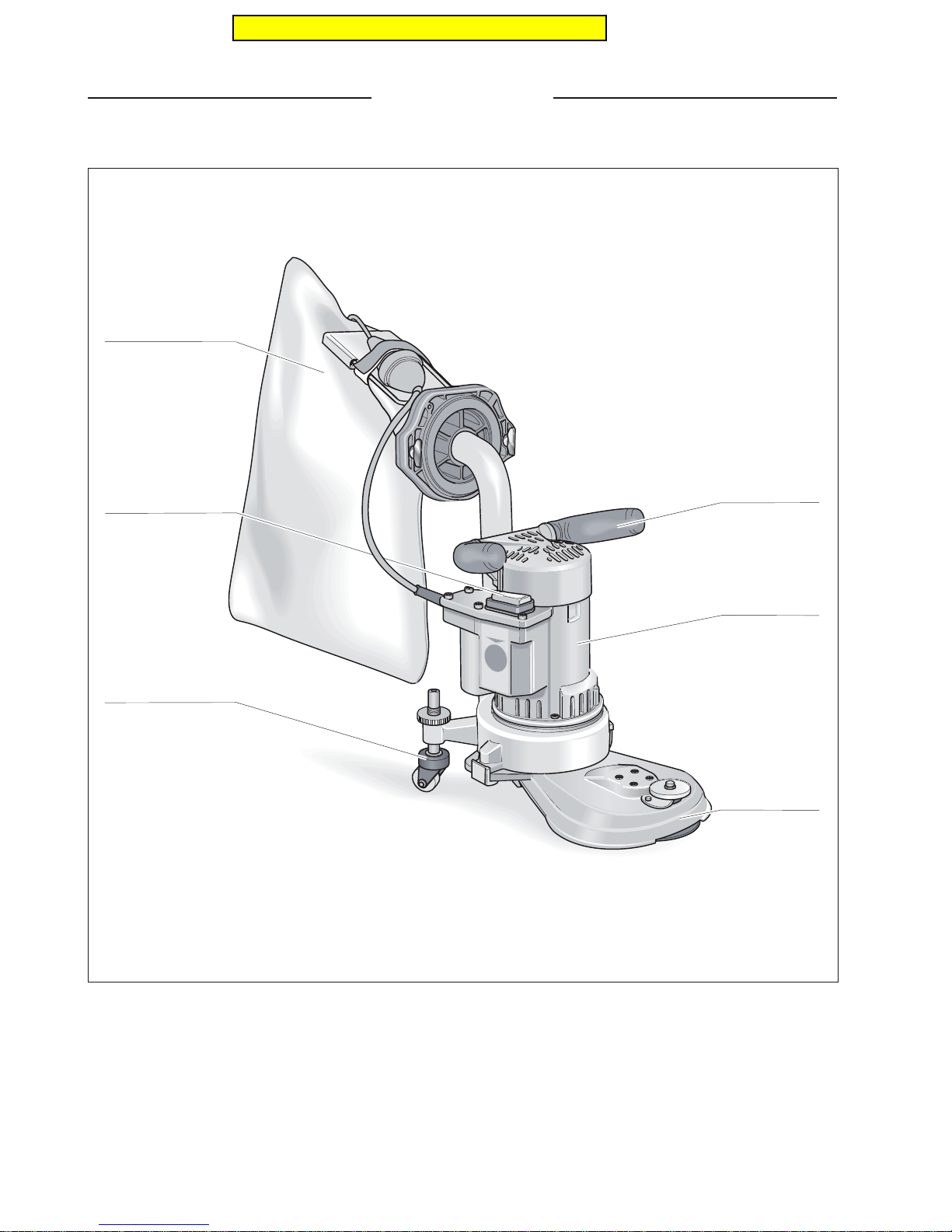
FLIP - ASSEMBLY
Dust bag
Switch
Guide roller
Handle
Motor
Attachment
Fig. 1 Main features of the edge-, corner- and stair-sanding machine FLIP
Pricing in this catalog is outdated
Page 3

CONTENTS
1. Introduction.................................................................................................................................................................................. 4
1.1 Features of the machine........................................................................................................................................................... 4
1.2 Description of the machine ..................................................................................................................................................... 4
1.3 Proper use as intended ............................................................................................................................................................ 4
1.4 Safety instructions .....................................................................................................................................................................5
1.5 Protective devices ..................................................................................................................................................................... 5
2. Technical data ............................................................................................................................................................................. 6
3. Getting started............................................................................................................................................................................. 7
3.1 Preparing the machine ............................................................................................................................................................. 7
3.2 Connecting the power supply cable ..................................................................................................................................... 8
3.3 Starting the machine .................................................................................................................................................................8
3.4 Switching off the machine ....................................................................................................................................................... 8
4. Working with the FLIP ...............................................................................................................................................................9
4.1 General application tips ........................................................................................................................................................... 9
4.2 Replacing the sanding disc ..................................................................................................................................................... 9
4.3 Emptying the dust bag............................................................................................................................................................. 11
5. Transport and storage............................................................................................................................................................. 14
6. Maintenance work and replacement of wearing parts.................................................................................................15
6.1 Tightening the V-belt ............................................................................................................................................................... 15
6.2 Changing the V-belt .................................................................................................................................................................16
6.3 Changing the steel sanding disc .......................................................................................................................................... 18
6.4 Changing the motor belt pulley.............................................................................................................................................18
6.5 Changing the carbon brushes .............................................................................................................................................. 19
6.6 Checking the dust suction system....................................................................................................................................... 20
6.7 Adjusting the guide rollers .................................................................................................................................................... 20
6.8 Changing the guide rollers.....................................................................................................................................................22
6.9 Adjusting the wall-protecting roller .................................................................................................................................... 22
6.10 Changing the wall-protecting roller .................................................................................................................................... 23
6.11 Cleaning the machine following restoration tasks .........................................................................................................24
7. Regular checkup according to safety regulations and VDE ........................................................................................ 24
8. Troubleshooting ........................................................................................................................................................................25
9. General safety information ....................................................................................................................................................26
10. Circuit diagram .......................................................................................................................................................................... 29
11. Spare parts................................................................................................................................................................................. 30
12. Service passport...............................................................................................................................
........................................43
13. Declaration of conformity ......................................................................................................................................................44
Pricing in this catalog is outdated
Page 4
INTRODUCTION
1
1.1 FEATURES OF THE MACHINE
In figure 1 (page 2), we have included the designations of the most
important components of the FLIP. Take your time to become
familiar with the machine.
1.2 DESCRIPTION OF THE MACHINE
The FLIP edge-sanding machine works with a sanding plate on
which Velcro sanding discs can be fastened. Traditional sanding
discs fastened with a tensioning screw can, of course, also be
used. The work zone is protected by the attachment. The fan
housing, on which the electric motor is mounted in vertical position,
is located on the attachment. A motor power supply cable is used
to connect the machine to the power supply system. The motor
switch with ON / OFF is located on the right-hand side of the motor
in the switch box. The machine is moved by means of two guide
rollers at the rear side of the machine. The handles are located on
top of the motor.
A rotable elbow piece mounted in a tube socket on the rear of the
fan housing, feeds the sanding dust into the dust bag. The dust
bag is connected to the elbow piece via a flange with two quickrelease fasteners. The power cord is fixed to the bag’s fixing bracket by a Velcro tape so that it is kept out of the working area of
the machine.
The FLIP can only be used for dry processing operations. Never
use the FLIP for wet processing operations (life-threatening risk)!
1.3 PROPER USE AS INTENDED
The edge-sanding machine FLIP is suitable for the dry sanding of
wooden floors, cork floors and wooden stairs in the professional
and rental business sectors.
Any other form of use without the approval of the manufacturer is
not permitted.
No wet processing operations!
Introduction
You have purchased a high-quality product
from LÄGLER. We wish you great success
with your FLIP. This machine was
manufactured using the most modern
methods of production. All LÄGLER
products are subjected to a thorough
inspection before leaving the factory.
Please read these operating instructions
carefully before you start working with
your FLIP for the first time. These operating
instructions include important information
on work safety and will give you answers
to many questions so that you can work
with the machine safely and without any
problems. If you cannot find a specific
subject in this manual, please refer to your
sanding instructions manual or contact our
service department. Our qualified service
technicians are extremely familiar with the
FLIP and are highly trained. They will
provide you with the best possible advice
and support.
Pricing in this catalog is outdated
Page 5

INTRODUCTION
1
1.4 SAFETY INSTRUCTIONS
Please read the danger warnings carefully and also instruct your
employees or colleagues accordingly. Otherwise, these persons
could be exposed to danger or be injured.
When the sanding disk is touching the floor, the machine must not
be switched on in order to prevent injuries.
Use the tools, accessories and spare parts that have been made
by LÄGLER for the FLIP only. Otherwise, this could result in damage
to the machine, the processed object or for the operator.
Make sure the dust bag is properly fastened in order to prevent
unnecessary and unhealthy dust emissions for the operator and
the environment.
Incorrect transport operations will result in machine damage.
To prevent any damage due to fire or explosions, the dust bag
must be emptied after the work has been completed and the
contents then be stored outdoors.
Keep well away from fire sources.
Do not smoke in a dusty environment (e.g. while working with
the machine or emptying out the dust)
Risk of a dust explosion.
The power supply cable must be kept out of the work zone in order
to prevent any damage to mechanical or electrical equipment.
To exclude the possibility of the machine being started
unintentionally, the power supply must be interrupted by removing
the power supply plug from the socket after the machine has been
switched off!
In case of correct machine operation, the mandatory dust emission
values will not be exceeded. When emptying the dust bag, it is
advisable to wear a respiratory protective mask P3 (Art. no. in
Section 11, Spare parts
).
1.5 PROTECTIVE DEVICES
The following parts of the machine are protective devices and must
therefore always be keep in perfect condition:
attachment cover, short / long = dust protection, protection
against V-belts
attachment, short / long = protection against sanding disc
Pricing in this catalog is outdated
Page 6

Note:
The motor data mentioned above refers to
machines used in the Federal Republic of Germany.
Exported machines may have other data that can
be seen on the motor type designation plate.
TECHNICAL DATA
2
Note:
The values mentioned above are emission
values and must not represent safe workplace
values as well. Although a correlation exists
between emission levels and immission
levels, it is not always possible to determine
whether additional precautionary measures
are required. Factors that can have an effect
on the immission level existing at the
workplace include the duration of the effects,
the characteristics of the work area and other
sources of noise, e.g. the number of machines
and other processing operations in the
vicinity. The permissible workplace values
may also vary from country to country. This
information, however, is intended to enable
the user to estimate the dangers and risks
better.
Technical data
Manufacturer ....................................................... Eugen LÄGLER GmbH
Machine type..................................................... edge-sanding machine
Serial number .................................................................. see rating plate
Year of manufacture ...................................................... see rating plate
Motor type ........................................................................ universal motor
Voltage................................................................................................... 230 V
Frequency................................................................................... 50 / 60 cps
Output ............................................................................................... 1.35 kW
Fuse ..........................................................................................................10 A
Insulation class ........................................................................................... F
Protection class................................................................................... IP 22
Protection system ...................................................................................... 2
Safety devices ......................................................... no-voltage release
.................................................................... thermal overload protection
Sanding disc diameter ..................................................... Ø 150 mm (6“)
Sanding disc diameter, corner attachment.......... Ø 61 mm (2 3/8“)
Sanding disc speed under load ............................. approx. 3100 rpm
Sanding disc speed under load,
corner attachment ...................................................... approx. 7750 rpm
Attachment height without wall-protecting roller ... 44 mm (1 3/4“)
Attachment height with wall-protecting roller ......... 58 mm (2 1/4“)
Height corner attachment...................................................51.5 mm (2“)
Attachment length, short version ............................... 155 mm (6 1/8“)
Attachment length, long version............................... 315 mm (12 3/8“)
Length corner attachment ............................................ 225 mm (8 7/8“)
Overall height without dust bag ................................ 460 mm (18 1/8“)
Overall length without dust bag
- with short attachment ............................................... 460 mm (18 1/8“)
- with long attachment................................................. 620 mm (24 3/8“)
- with corner attachment ............................................ 530 mm (20 7/8“)
Overall width................................................................... 260 mm (10 1/4“)
Total weight....................................................................... 9.8 kg (21.6 lbs)
Dust emissions at workplace ............ < 0,2 mg/m
3
(0.0024 gr./cu.yd.)
Workplace-related noise emission values ........................ 86 dB (A)
Vibration total value a
hv
.....................................................................................................
< 2.5 m/s²
(measured at the handle)
Application purposes
Dry edge-sanding and stair-sanding of wooden floors and cork
floors.
Not to be used for any wet processing operations!
Pricing in this catalog is outdated
Page 7
3
This section describes how to put the FLIP into service on site. In
order to prevent damage and malfunctions, you should proceed in
the order of steps mentioned below.
3.1 PREPARING THE MACHINE
1 Unpack the machine carefully. Dispose of the packing
materials according to environmental regulations.
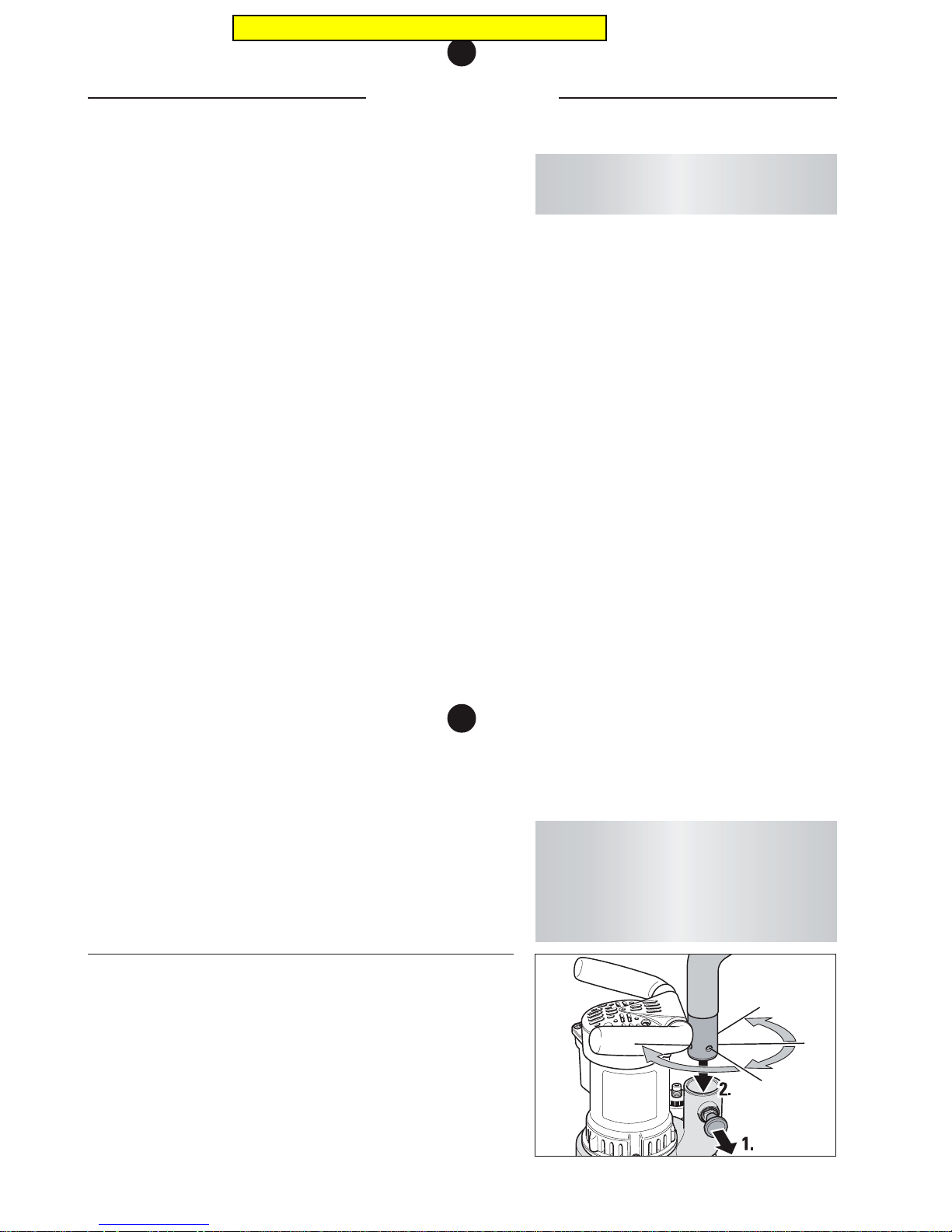
2 Pull out the stop bolt on the suction socket of the fan housing
and at the same time insert the fan tube in the suction socket (Fig. 2).
3 Turn the fan tube so that the opening of the elbow piece is
facing the back and the stop bolt locks home when it is let go.
Basic equipment
Machine ready for use, dust bag, extension cable 3 x 1.5 mm
2
- 10 m
long, universal spanner, respiratory protective mask (P3) and
operating instructions.
Special accessories
Attachment long, corner attachment, foldable earmuff type Pocket.
Wearing parts
Please check the condition of the wearing parts mentioned below
at regular intervals in order to be able to work safely and optimally
at all times:
• Extension cable renew in case of damage
• Motor cable renew in case of damage
• Velcro disc renew in case of wear or damage
• V-belt renew in case of wear
• Dust bag renew in case of wear or damage
• Guide roller renew in case of wear or damage
• Switch renew in case of wear or damage
• Paper tensioning disc renew in case of wear or damage
• Torx-srew for paper tension renew in case of wear or damage
• Carbon brushes renew in case of wear
• Motor belt pulley renew in case of wear
3
Getting started
The relevant article numbers are given in the
spare parts lists in
Section 11
.
Please note that the packaging serves as
a transport container for the machine,
accessories and sanding medium,
furthermore, the machine can be sent
without risk should there be any problems.
GETTING STARTED
Fig. 2 Withdraw the stop bolt and feed the tube into the
connector socket.
Pricing in this catalog is outdated
Page 8
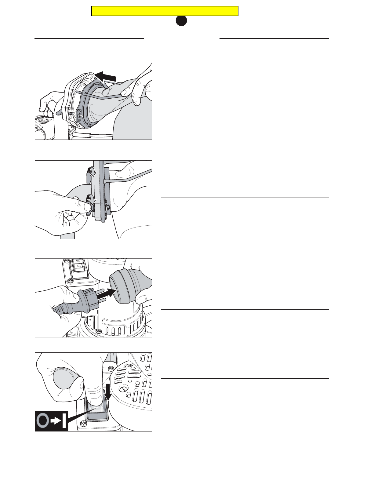
Fig. 3 Push the dust bag over the locating flange and fix
with the two metal studs.
Fig. 4 Secure the dust bag using the quick-release
fasteners.
Fig. 6 Use the switch to switch on and off.
Fig. 5 Connect the motor cable to the extension cable.
4 The fan tube can be turned through 360°, whereby four fixed
positions are possible in which the stop bolt snaps into place
in the tube.
Always select one of these four positions to avoid
accidents or damage to the machine!
5 Push the dust bag opening over the locating flange fixed to
the end of the elbow piece and fix the dust bag using the
two metal studs (Fig. 3).
6 Fix the dust bag to the locating flange using the two quick-
release fasteners (Fig. 4).
3.2 CONNECTING THE POWER SUPPLY CABLE
1 Insert the plug of the motor cable in the coupling of the
extension cable (Fig. 5).
2 Fasten the extension cable coupler using the Velcro loop
on the dust bag.
3 Insert the extension cable in a suitably protected 230-volt
socket or 110-volt socket according to specified power
supply.
3.3 STARTING THE MACHINE
The FLIP is now ready to be started. When starting the machine,
the sanding disc must be raised from the floor therefore, tilt the
machine back first. You may then use the switch to start the
machine (Fig. 6).
3.4 SWITCHING OFF THE MACHINE
To switch off the machine, tilt it back so that the sanding disc is
raised off the floor and press the switch. Wait until the sanding
disc comes to a standstill before you stand the machine back on
the sanding disc.
Never let the machine run unattended and always pull the power
supply plug out of the socket when you have finished working
with the machine.
GETTING STARTED
3
Pricing in this catalog is outdated
Page 9
WORKING WITH THE FLIP
4
4.1 GENERAL APPLICATION TIPS
The FLIP is a very versatile machine. The required attachment can
be replaced in a matter of seconds. The FLIP is used for fine
sanding of transitions, borders, edges, corners and stairs.
Deep sanding marks due to the selection of a too coarse
sandpaper grain size can be prevented by starting the first sanding
operation with a fine sandpaper grain size to the extent possible.
Prevent sanding marks made by previously used sandpaper grain
sizes by adhering to the order of the sandpaper grain sizes and
never skip more than a sandpaper grain size. Following each
sanding operation, vacuum the floor thoroughly.
After changing over to a new sanding disc, start working in poorly
lit areas in the room in order to remove the initial aggressiveness
of the sanding disc.
Bear in mind that the FLIP operates at very high cutting speeds.
For this reason, danger of burn marks exists for finer sandpaper
grain sizes!
Do not apply excessive pressure to the attachment. This will
significantly worsen the sanding finish by causing deep scratches,
and could cause the motor to become overheated and switch off.
Please refer to the LÄGLER sanding instructions for additional
important and interesting application tips.
4.2 REPLACING THE SANDING DISC
Depending on the processing operation, you will use various
sandpaper grain sizes. To replace the sanding disc, proceed in
the following manner:
4.2.1 VELCRO SANDING DISCS
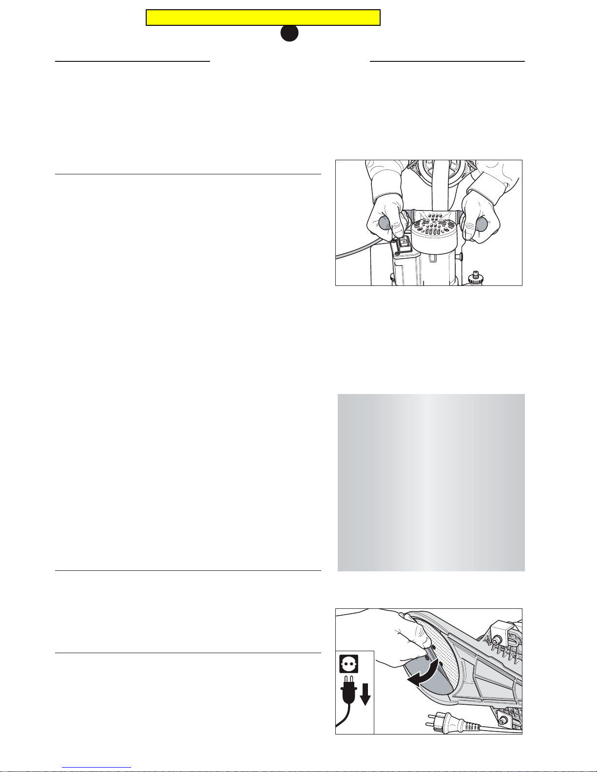
1 Switch off the machine.
2 Always pull the power supply plug out of the socket!
3 Turn the machine upside down or lay it on its side, avoiding
damage to the floor and machine.
Working with the FLIP
Fig. 7 Guide the FLIP with both hands.
Fig. 8 Simply pull off the Velcro sanding disc ...
For more information free of charge,
please apply to: within Germany
- Tel.: 0800 / 52 34 537
- Fax: 0800 / 48 66 353
within the USA
- Tel.: 800-848-6635
or
- Tel.: +49 - 7135 - 98 90-0
- Fax: +49 - 7135 - 98 90-98
- e-mail: [email protected]
- Internet: http://www.laegler.com
Pricing in this catalog is outdated
Page 10
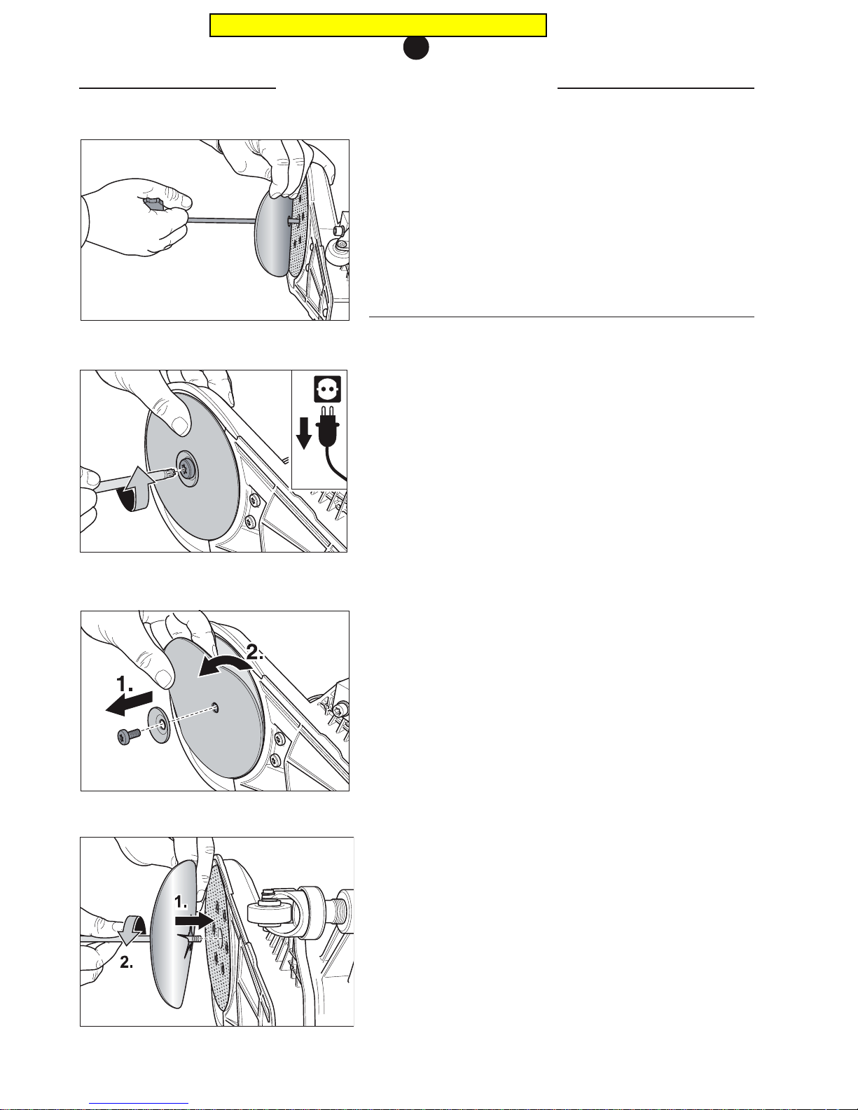
4 Pull off the worn-out Velcro sanding disc from the sanding
plate (Fig. 8).
5 Place a new Velcro sanding disc on the sanding plate. The
Velcro sanding disc must be seated in centered position on
the sanding plate. A drilled hole in the center of the sanding
disc and the universal spanner make this step easier (Fig. 9).
4.2.2 CONVENTIONAL SANDING DISCS
1 Switch off the machine.
2 Always pull the power supply plug out of the socket!
3 Turn the machine upside down or lay it on its side, avoiding
damage to the floor and machine.
4 Use the universal spanner to loosen the fixing screw of the
paper tensioning device (Fig. 10).
5 Rotate the fixing screw all the way out. Remove the paper
tensioning disc from the sanding plate and put these parts
aside (Fig. 11).
6 Put on a new sanding disc and insert the fixing screw in the
sanding plate together with the paper faceplate (Fig. 12).
7 Turn the fixing screw in the sanding plate using the univer-
sal spanner (Fig. 12); make sure the sanding disc is fastened
in centered position on the sanding plate.
8 Tighten the fixing screw with the universal spanner until it
is hand-tight.
Always mount one sanding disc only, since otherwise the sanding
results will be unsatisfactory and the dust suction system not be
fully operational!
Fig. 9 ... and mount the new disc in centered position and
press down.
Fig. 10 Remove conventional sanding disc by loosening the
fixing screw with the universal spanner and ...
Fig. 12 ... mount a new disc and assemble again.
Fig. 11 ... after removing, take off the paper faceplate, ...
REPLACING THE SANDING DISC
4
Pricing in this catalog is outdated
Page 11
EMPTYING THE DUST BAG
4
4.3 EMPTYING THE DUST BAG
The dust bag must be emptied when it is one-third full at the very
latest in order to prevent a deterioration of the suction
performance due to the missing filtering surface area. The horizontal line on the outside of the dust bag marks the maximum filled
level. When emptying the dust bag, it is advisable to wear a
respiratory protective mask (P3).
To empty the dust bag proceed as follows:
1 Switch off the machine.
2 Always pull the power supply plug out of the socket!
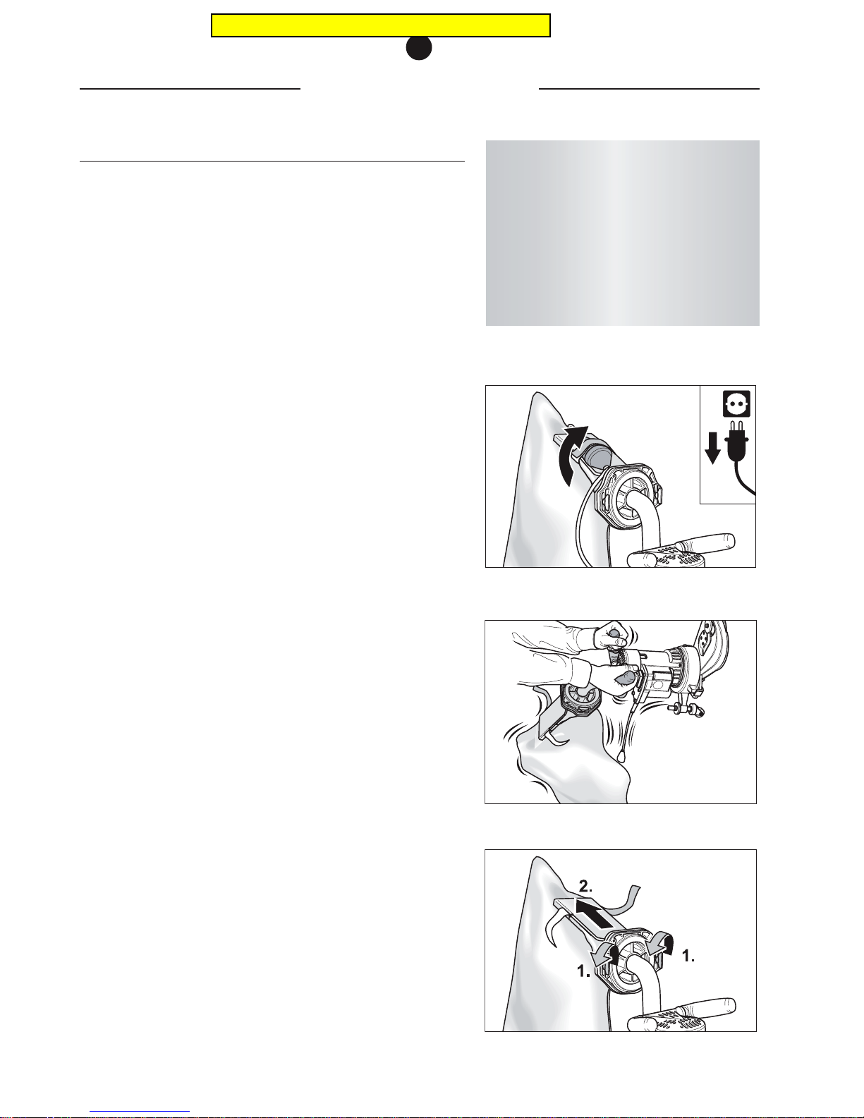
3 Remove the extension cable coupler from the Velcro loop
on the dust bag (Fig. 13).
4 Before emptying, shake the dust residue into the dust bag
(Fig. 14).
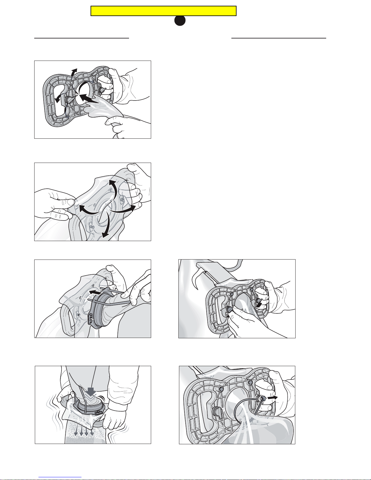
5 Open the two quick-release fasteners on the locating flange
(fig. 15).
6 Slowly pull the dust bag off the locating flange (Fig. 15).
7 Hold the handle of the emptying fixture and insert a waste
bag from the ribbed side through the opening in the centre
of the fixture (Fig. 16).
8 Pull the waste bag over the emptying fixture from behind
(Fig. 17).
9 Take hold of the emptying fixture with the waste bag in one
hand and the dust bag in the other. Hold the dust bag at a
slight angle to prevent dust escaping.
10 Insert the dust bag into the emptying fixture. Make sure
the rods are in the correct position. The pins have to fit into
the openings provided (Fig. 18).
11 Apply light pressure to insert the dust bag completely into
the emptying fixture. The pins on the dust bag rods pierce
the waste bag and prevent it slipping (Fig. 18).
ATTENTION!
To prevent fire and explosion damage the dust
bag must always be removed from the machine
and emptied following sanding. The filled
waste bag may only be disposed of in a noncombustible container!
Close this container and always store it and
the dust bag outdoors (Fig. 24)!
Fig. 15 Open the two quick-release fasteners and pull off
the dust bag.
Fig. 13 Remove the coupler from the Velcro loop on the dust
bag.
Fig. 14 Shake the dust residue into the dust bag.
Pricing in this catalog is outdated
Page 12
EMPTYING THE DUST BAG
4
12 Fix the emptying fixture to the dust bag by turning the two
quick-release fasteners through 90° clockwise (Fig. 19).
13 Empty the dust bag into the waste bag by shaking it
vigorously (Fig. 20).
14 Seal the filled waste bag before removal using the cable
binder provided (Fig. 21).
15 Open the two quick-release fasteners on the emptying
fixture (Fig. 22).
Fig. 17 Pull the waste bag over the fixture.
Fig. 18 Insert the dust bag.
Fig. 19 Fix the emptying fixture to the dust bag.
Fig. 20 Empty the dust bag by shaking it vigorously.
Fig. 21 Seal the waste bag using a cable binder.
Fig. 16 Insert the waste bag in the emptying fixture.
Pricing in this catalog is outdated
Page 13
EMPTYING THE DUST BAG
4
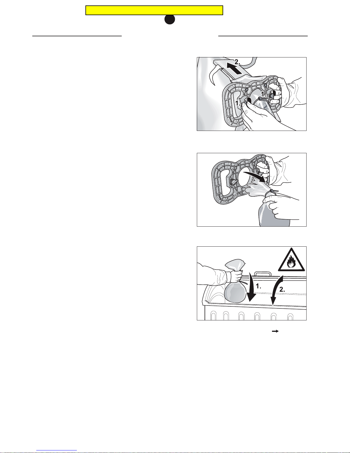
16 Remove the emptying fixture from the dust bag. Keep the
dust bag tilted at a slight angle to prevent any residue dust
falling back into the dust bag (Fig. 22).
17 Reattach the dust back to the machine in reverse order.
18 Remove the filled waste bag from the emptying fixture (Fig.
23) and place it in a non-combustible container (Fig. 24).
Fig. 22 Loosen the quick-release fasteners and remove the
dust bag.
Fig. 23 Remove the waste bag from the emptying fixture.
Fig. 24 Throw the filled waste bag into a non-combustible
container and keep this closed
fire hazard!
Pricing in this catalog is outdated
Page 14
If the machine must be stored for a longer period of time, take the
necessary measures to ensure dry and frost-free storage with
minimum temperature fluctuations.
Professional tip:
Use the transport packaging to store the machine.
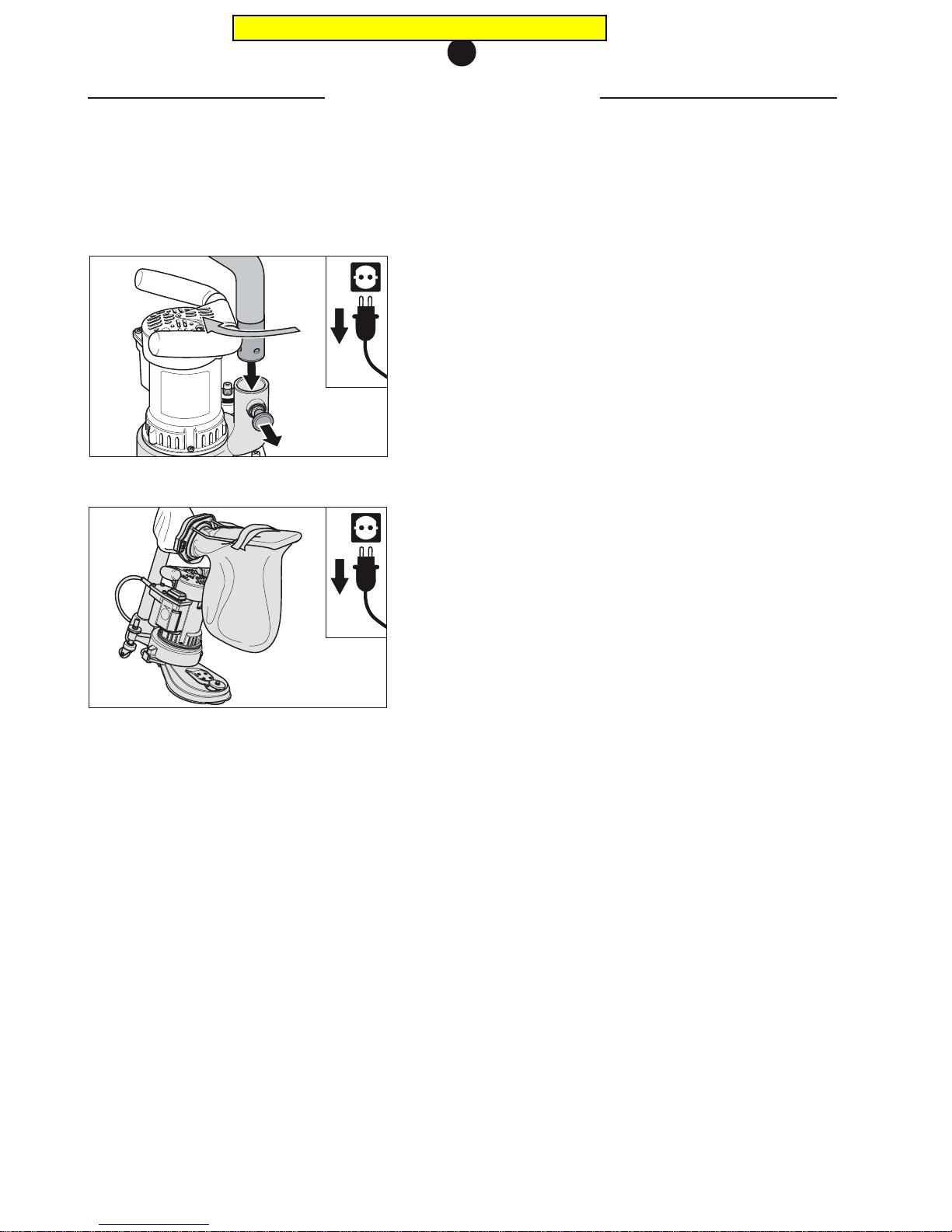
So that the FLIP requires less space for transport or storage,
1 pull the stop bolt in the fan housing (Fig. 25),
2 at the same time, turn the fan tube until the dust bag is
located over the attachment and the stop bolt noticeably
snaps into place when let go (Fig. 25).
The stop bolt must lock home to avoid accidents or damage
to the machine!
You can now easily carry the machine using the elbow piece (Fig.26).
Transport and storage
TRANSPORT AND STORAGE
5
Fig. 26 Carrying the FLIP.
Fig. 25 Pull out the stop bolt and turn the fan tube.
Pricing in this catalog is outdated
Page 15
MAINTENANCE WORK AND REPLACEMENT OF WEARING PARTS
6
Maintenance work and replacement
of wearing parts
You can perform various maintenance tasks on your own. These
maintenance tasks are described in the following sections. Extensive maintenance tasks, especially on the electrical equipment
must be carried out by an expert.
6.1 TIGHTENING THE V-BELT
The V-belt must be re-tightened from time to time. Proceed in the
following manner:
1 Switch off the machine and always pull the power supply
plug out of the socket!
2 Turn the machine upside down, place it on its side or with
the motor housing on a table, at the same time avoiding
damage to the floor and machine.
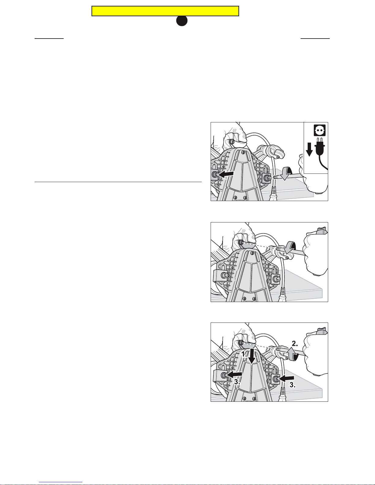
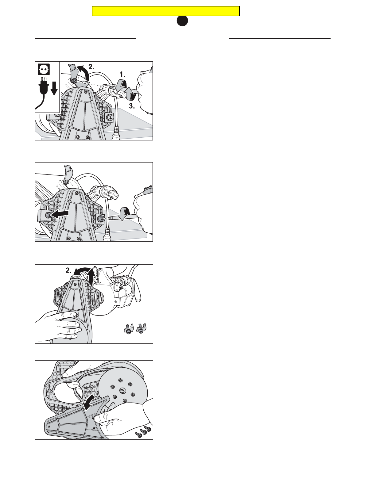
3 Use the universal spanner to undo the two screws with which
the attachment is fastened on the fan housing (Fig. 27).
4 Use the universal spanner to undo the screw with which
the belt tightener plate is fastened (Fig. 28).
5 Grab the FLIP at the suction socket and press the belt
tightener plate forward with your thumb at the same time,
while using the other hand to retighten the three screws
with the universal spanner (Fig. 29).
6 Do not tighten the V-belt too much in order to prevent
excessive wear of the V-belt and V-belt pulley.
Fig. 29 Hold the FLIP firmly at the suction socket, press on
the belt tightener plate and tighten the three screws.
Fig. 27 Undo the two screws with which the attachment is
fastened.
Fig. 28 Undo the screw with which the belt tightener plate
is fastened.
Pricing in this catalog is outdated
Page 16
CHANGING THE V-BELT
6
6.2 CHANGING THE V-BELT
Make sure that original LÄGLER V-belts are used (Art. no. in
Section
11, Spare parts
).
The V-belt must be replaced when the V-belt cannot be retightened because the screws for fastening the attachment are at
the end of the long holes.
1 Switch off the machine and always pull the power supply
plug out of the socket!
2 Turn the machine upside down, place it on its side or with
the motor housing on a table, at the same time avoiding
damage to the floor and machine.
3 Undo the belt tightener plate screw using the universal
spanner, turn it so that it faces the back and then retighten
the screw (Fig. 30).
4 Use the universal spanner to remove the two screws,
washers and guide angles that fix the attachment and place
the parts to one side (fig. 31).
5 Remove the attachment from the machine and put away the
attachment with the sanding disc facing upward (Fig. 32).
6 Use the universal spanner to remove the fixing screws of
the attachment cover and remove it from the attachment
(Fig. 33).
7 Turn the attachment around.
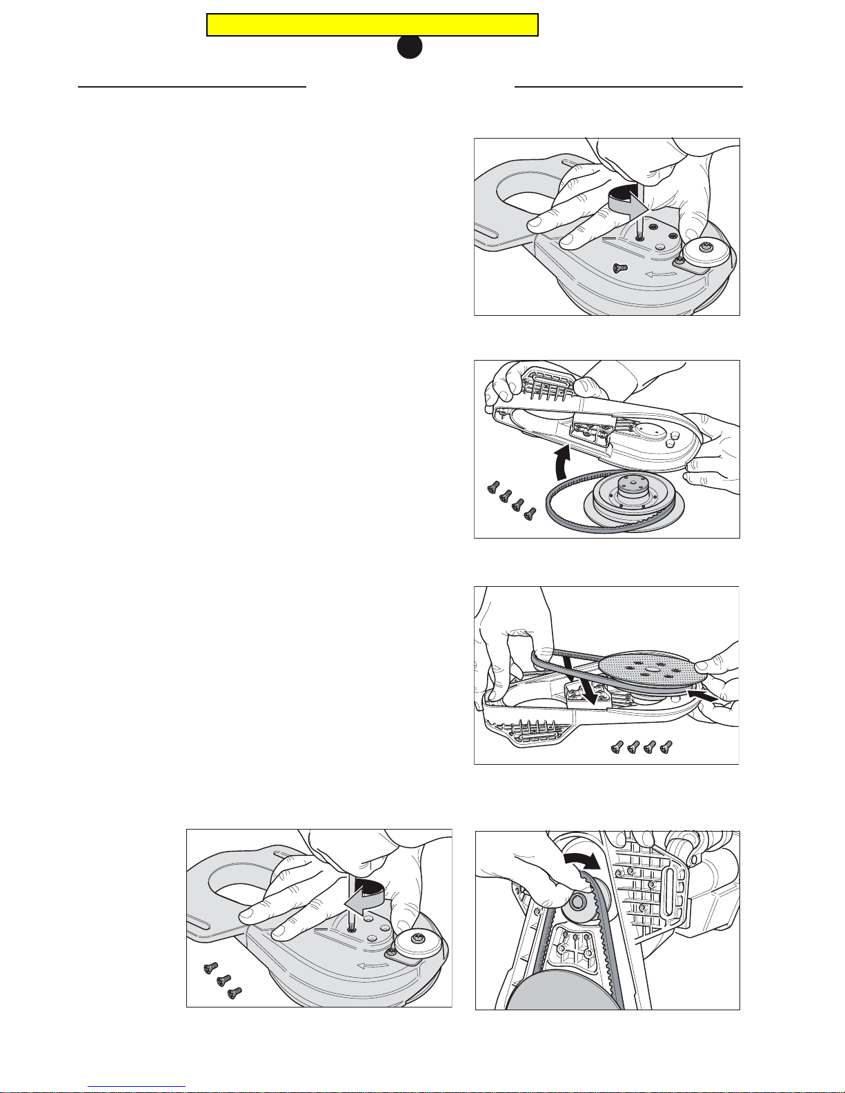
8 Use the universal spanner to loosen the four fixing screws
of the steel sanding disc and unscrew them (Fig. 34).
9 Then remove the attachment from the steel sanding disc
(Fig. 35).
10 Remove the worn-out V-belt from the attachment.
Fig. 30 Loosen the screw, turn away the belt tightener plate
and retighten the screw.
Fig. 31 Remove the two screws with which the attachment
is fastened.
Fig. 32 Remove the attachment from the machine.
Fig. 33 Remove the attachment cover.
Pricing in this catalog is outdated
Page 17
CHANGING THE V-BELT
6
11 Clean the two belt pulleys and the attachment. Wear a
respiratory protective mask (P3) as required.
12 Place the new V-belt on the steel sanding disc.
13 Insert the steel sanding disc and the V-belt in the
attachment. Ensure that the holes in the steel sanding disc
are aligned with the holes of the attachment (Fig. 36).
14 Make sure that the sanding plate can be rotated by hand
and that the V-belt was correctly installed in the
attachment.
15 Tighten the four countersunk head screws for fixing the
steel sanding disc using the universal spanner (Fig. 37).
16 Then place the attachment on the machine by inserting the
V-belt into the motor belt pulley first and then the
attachment on the machine (Fig. 38).
17 Fit the attachment cover.
18 Now turn the screws in the screw thread of the fan housing.
Ensure that the guide angles and washers are fitted under
the screws.
19 Now tighten the V-belt as described in
Section 6.1
.
Following a running-in period, check the belt again!
Fig. 34 Unscrew the four fixing screws of the steel sanding
disc.
Fig. 35 Remove the attachment from the steel sanding disc.
Fig. 36 Insert the steel sanding disc into the attachment
with the V-belt. Ensure that the holes in the steel
sanding disc are aligned with the holes in the
attachment.
Fig. 38 Insert the V-belt into the motor belt pulley.
Fig. 37 Tighten the four countersunk head screws to fix the
steel sanding disc.
Pricing in this catalog is outdated
Page 18
6.3 CHANGING THE STEEL SANDING DISC
If the V-belt is being changed, it has to be determined whether the
belt pulley of the steel sanding disc is worn-out. If that is the case
you must proceed in the following manner:
1 Switch off the machine and always pull the power supply
plug out of the socket!
2 Dismantle the attachment and the steel sanding disc, in
accordance with
Section 6.2.
3 Reassemble the attachment with a new steel sanding disc
(complete) in the reversed order, in accordance with
Section 6.2.
6.4 CHANGING THE MOTOR BELT PULLEY
Use original LÄGLER motor belt pulleys only (Art. no. in
Section 11,
Spare parts
). Due to the high motor speed of the FLIP, the motor
belt pulley is subjected to increased wear. The belt pulley should
therefore be replaced on time in order to prevent excessive V-belt
wear.
1 Switch off the machine and always pull the power supply
plug out of the socket!
2 Remove the attachment as described in
Section 6.2
.
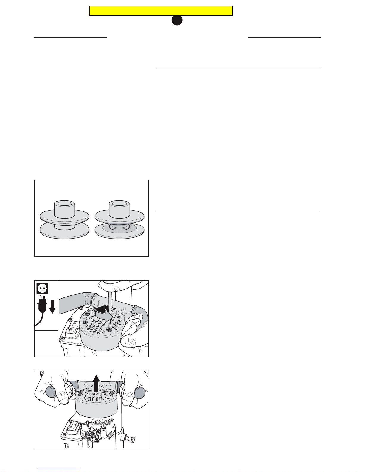
3 Loosen the four fixing screws of the handle and remove it
from the motor housing. Ensure that none of the parts fall
into the motor (Fig. 40 + 41).
4 Now hold the upper end of the motor shaft tight with an SW
10 spanner and use a pair of pliers to undo the motor belt
pulley from the motor shaft (normal right-handed thread).
5 Clean the contact surface of the motor belt pulley and the
shaft butt end completely.
6 IMPORTANT:
Oil the machined seat of the motor belt pulley drill hole.
CHANGING THE STEEL SANDING DISC
6
Fig. 41 ... remove the handle.
Fig. 39 On the left-hand side, a new belt pulley, and on the
right-hand side, a run-in belt pulley that must be
replaced.
Fig. 40 Undo the four fixing screws and ...
Pricing in this catalog is outdated
Page 19
CHANGING THE CARBON BRUSHES
6
7 Rotate the new motor belt pulley onto the motor shaft.
8 Tighten the motor belt pulley using the spanner and pliers.
9 Fit the handle to the motor housing.
10 Then install the attachment and tighten the V-belt as
described in
Section 6.2
.
6.5 CHANGING THE CARBON BRUSHES
Carbon brushes (Art. no. in
Section 11, Spare parts
) with safety
contacts are used to prevent the collector from being damaged
by completely worn-out carbon brushes. These safety contacts
will switch off the machine automatically when the wear limit is
reached. The carbon brushes should, however, be replaced at
least once a year in order to prevent damage to the machine!
1 Switch off the machine and always pull the power supply
plug out of the socket!
2 Undo the four fixing screws of the handle and remove it
from the motor housing, ensuring that no small parts fall
into the motor (Fig. 40 + 41).
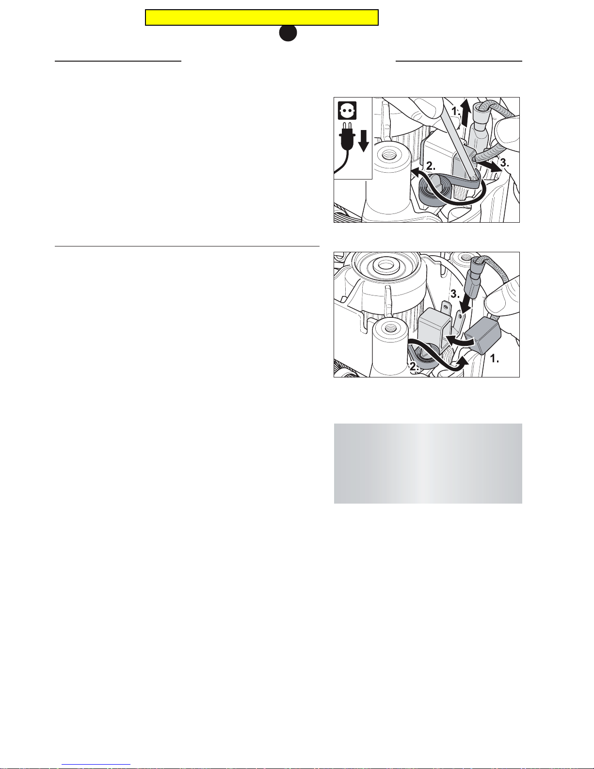
3 Pull off the connector of one of the carbon brushes from
the carbon holder (Fig. 42).
4 Use the universal spanner to turn the brass pressure clamp
so that it faces the back and remove the worn carbon brush
(Fig. 42).
5 Insert the new carbon brush and turn back the brass
pressure clamp (Fig. 43).
6 Fix the carbon brush connector on the contact provided.
Install the carbon brush cable as for the other old carbon
brush that is still installed, to avoid subsequent pinching of
the cable (Fig. 43).
7 Now replace the second carbon brush in the same way.
8 Now refit the handle to the motor housing.
Fig. 42 Pull off the connector, turn the brass pressure clamp
to the back and remove the carbon brush.
Fig. 43 Insert the new carbon brush, turn back the brass
pressure clamp and attach the connector.
Professional tip:
You should have a qualified electrician clean
the collector by removing the carbon fines every
other time the carbon brushes are changed to
extend the service life of the motor!
Pricing in this catalog is outdated
Page 20
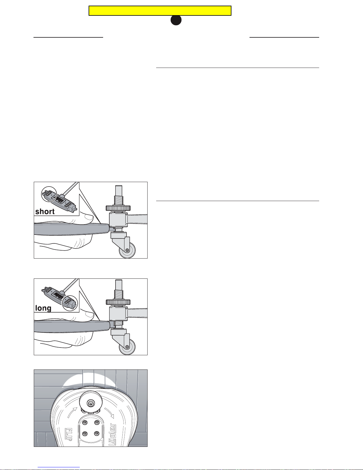
6.6 CHECKING THE DUST SUCTION SYSTEM
In order to guarantee optimal dust suction for your safety and for
the safety of other persons, the following items must be taken into
account:
• Always use original LÄGLER dust bags FLIP (Art. no. in
Section 11, Spare parts
).
• Do not use any damaged dust bags.
• Ensure that the guide rollers are correctly positioned.
• Check the suction system for any clogged-up material or
deposits.
• Make sure that the dust bag and locating flange are
connected properly.
6.7 ADJUSTING THE GUIDE ROLLERS
The position of the guide rollers will have an effect the sanding
results and the aggressiveness of the machine. For rough sanding
tasks, a large setting angle is selected. For fine sanding tasks, a
flat setting angle.
The two alignment marks on the universal spanner can be used to
set a position for the guide rollers, which is suitable for both rough
and fine sanding work, for the short and long attachment.
This is achieved by holding the corresponding alignment mark of
the universal spanner, that depends on the attachment used,
between the guide roller and the fan housing and this spacing is
then set (see below for procedure).
This setting allows a horizontal and even sanding setting, which
does not overload the machine and leads to an even and attractive
sanded finish.
In special cases the setting must be adjusted to the circumstances,
however it is easy to find the standard setting again using the universal spanner.
The high cutting speed of the machine allows you to work fast.
The machine must be moved quickly without applying extra
pressure. If a higher amount of removed material is demanded,
the setting angle must be adjusted to a steeper setting!
CHECKING THE DUST SUCTION SYSTEM
6
Fig. 44 Standard setting for the short attachment and the
corner attachment.
Fig. 45 Standard setting for the long attachment.
Fig. 46 Correctly adjusted, machine is sanding centrically.
Pricing in this catalog is outdated
Page 21
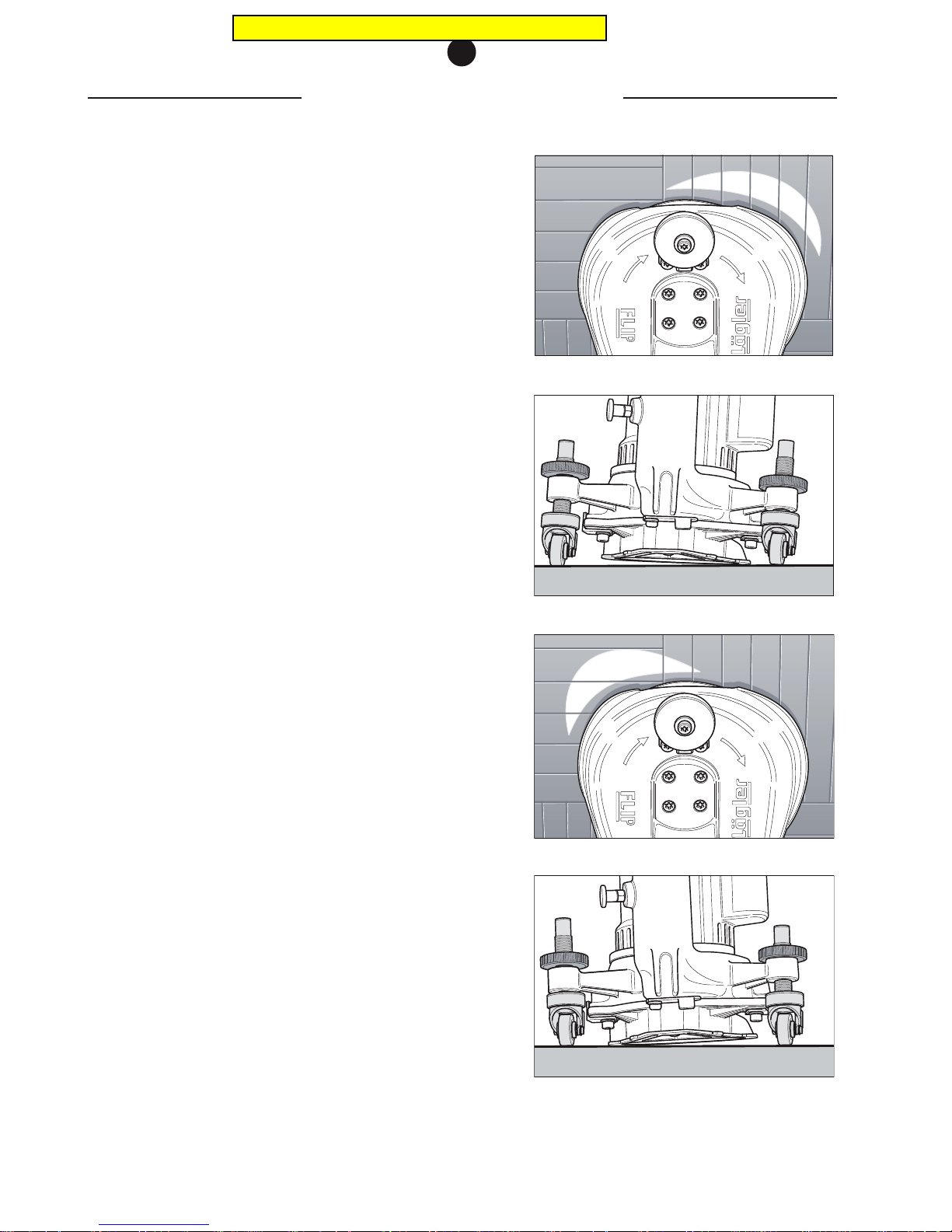
To adjust the guide rollers, proceed in the following manner:
1 Switch off the machine and always pull the power supply
plug out of the socket!
2 Loosen the locknut of the guide roller to be adjusted.
3 Hold the appropriate universal spanner alignment mark for
attachment used between the guide roller and fan housing,
namely so that the lettering on the spanner faces towards
the fan housing (Fig. 44 + 45).
Alignment mark - short attachment: short
- long attachment: long
- corner attachment: short
4 Now turn the guide roller in the direction required and re-
tighten the locknut.
5 Perform a trial sanding operation and check the sanding
results (Fig. 46 – 50). Should you require a steeper or flatter
setting, loosen the locknut again and turn the guide roller
one or two turns in the relevant direction and then tighten
the locknut again.
Fig. 47 Sanding zone too far to the right means, ...
Fig. 48 ... the left-hand wheel lifts the machine too far.
Fig. 50 ... the right-hand wheel lifts the machine too far.
Fig. 49 Sanding zone too far to the left means, ...
ADJUSTING THE GUIDE ROLLERS
6
Pricing in this catalog is outdated
Page 22
6.8 CHANGING THE GUIDE ROLLERS
Use original LÄGLER guide rollers only (Art. no. in
Section 11,
Spare parts
).
1 Switch off the machine and always pull the power supply
plug out of the socket!
2 Remove the locknut.
3 Rotate the guide roller completely out of the fan housing.
4 Rotate the new guide roller into the fan housing.
5 Set the position of the guide roller using the universal
spanner
(Section 6.7)
. Mount the locknut and tighten it.
6 Check the machine setting
(Section 6.7.5)
.
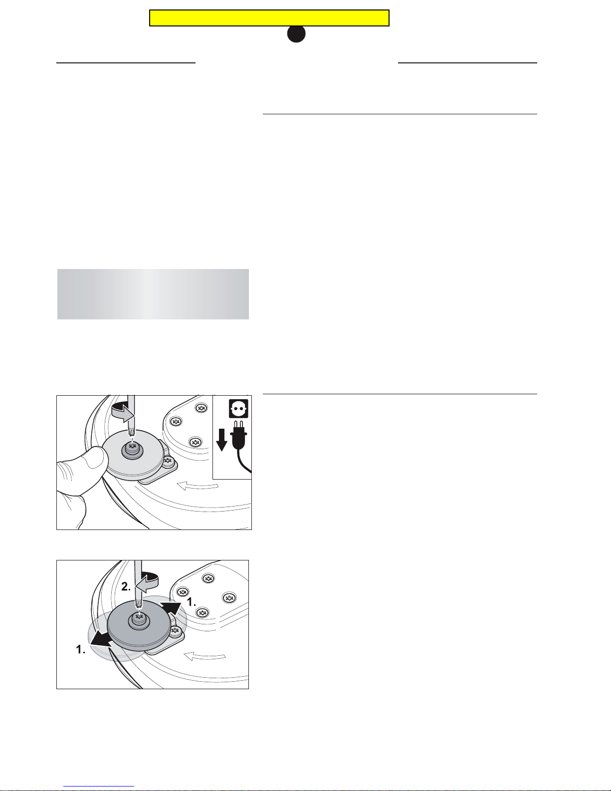
6.9 ADJUSTING THE WALL-PROTECTING ROLLER
Adjusting the wall-protecting roller can avoid various wall shapes
or skirting boards being damaged, or sanded too.
1 Switch off the machine and always pull the power supply
plug out of the socket!
2 Use the universal spanner to undo the screw in the middle
of the wall-protecting roller (Fig. 51).
3 Push the wall-protecting roller into the position you require
and then retighten the screw (Fig. 52).
4 Check the position by placing the switched off FLIP against
the wall so that the wall-protecting roller lies against it.
5 The sanding plate must not touch the wall otherwise push
the wall-protecting roller in the relevant direction.
CHANGING THE GUIDE ROLLERS
6
Professional tip:
A light oil film on the thread of the guide roller
makes the adjusting work easier!
Fig. 51 Undo the screw in the middle of the wall-protecting
roller ...
Fig. 52 ... and position.
Pricing in this catalog is outdated
Page 23
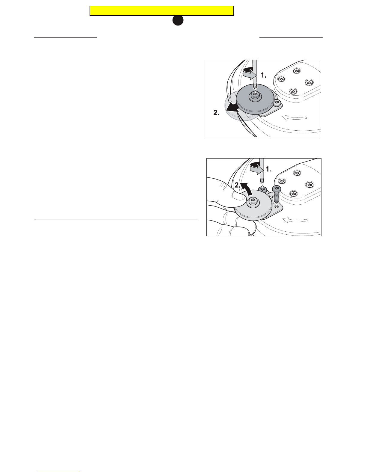
If you deliberately want to sand right up to the wall, you can push
the wall-protecting roller right out of the working area.
You can completely remove the wall-protecting roller if you want
to sand under low radiators or cupboards:
1 Switch off the machine and always pull the power supply
plug out of the socket!
2 Use the universal spanner to undo the screw in the middle
of the wall-protecting roller and push it into the front
position (Fig. 53).
3 Remove the two screws attaching the holder of the wall-
protecting roller to the attachment and remove the
complete wall-protecting holder (Fig. 54).
6.10 CHANGING THE WALL-PROTECTING ROLLER
Use original LÄGLER wall-protecting rollers only (Art. no. in
Section
11, Spare parts
).
1 Switch off the machine and always pull the power supply
plug out of the socket!
2 Use the universal spanner to remove the screw in the
middle of the wall-protecting roller (Fig. 53, 1.).
3 Remove the old wall-protecting roller.
4 Insert the bush in the new wall-protecting roller and place
it on the holder for the wall-protecting roller with a washer
on each side. Ensure that the middle of the roller is located
over the nut in the holder.
5 Turn the screw through the bush drill hole into the nut.
6 Adjust the position of the wall-protecting roller according
to your needs
(Section 6.9)
.
CHANGING THE WALL-PROTECTING ROLLER
6
Fig. 54 Remove the fixing screws and take off the complete
wall-protecting roller.
Fig. 53 Loosen the screw and move the wall-protecting
roller.
Pricing in this catalog is outdated
Page 24
6.11 CLEANING THE MACHINE FOLLOWING
RESTORATION TASKS
Following restoration tasks, residual material consisting of
adhesive, wax or sealing lacquer may have accumulated on the
belt pulleys or in the attachment.
This can impair the running characteristics of the machine and
reduce the suction performance. This kind of soiling is indicated
in most cases by unsteady running, difficult starting, reduced
working speed and increased development of noise. The suction
performance also decreases. In this case, the V-belt must be
dismantled as described in
Section 6.2
and the attachment as well
as the flanks of the belt pulley be cleaned. Check the fan for any
deposits. Wear a respiratory protective mask (P3).
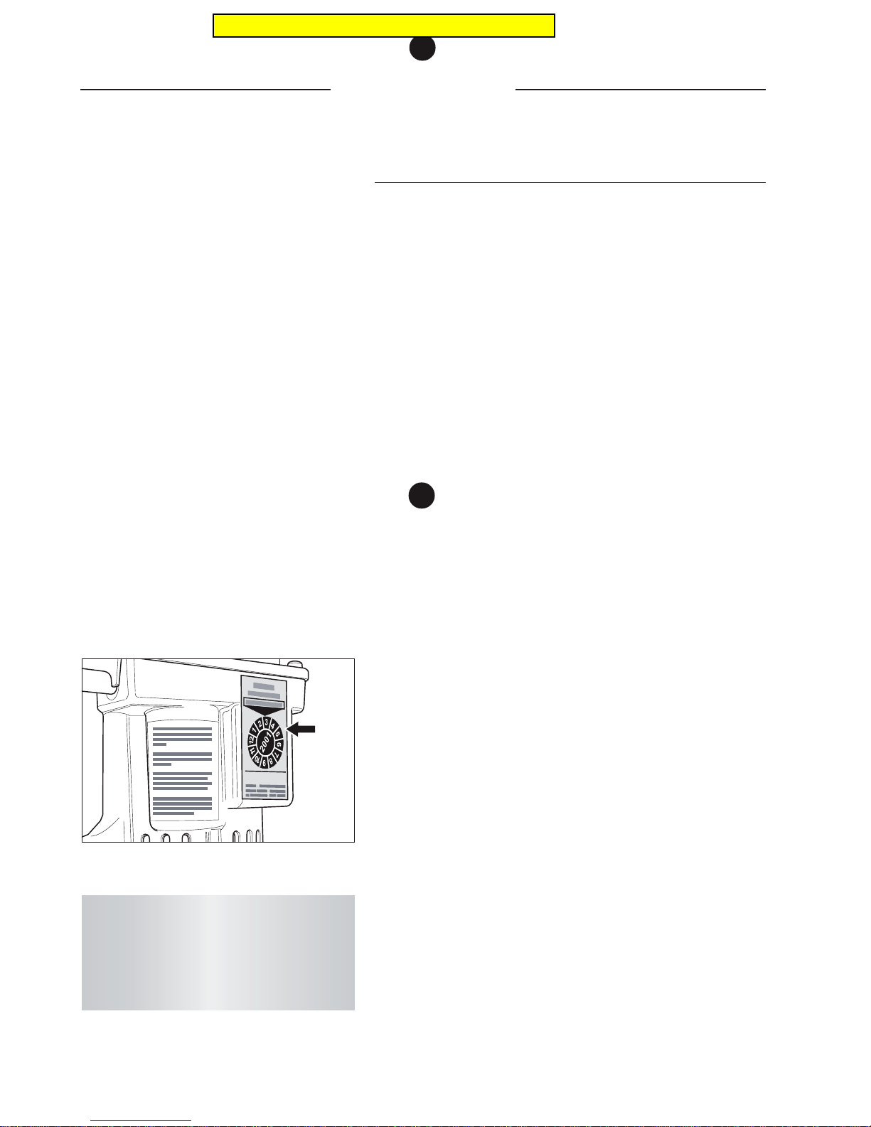
REGULAR CHECKUP
7
7
Regular checkup according to safety
regulations and VDE
The electrical operating equipment and machine parts must be
inspected at least once a year by an expert with respect to
electrical and mechanical safety, then be repaired as required,
and afterwards the operational safety must be confirmed by the
attachment of an inspection label on the machine.
The elements required for the dust suction system must be checked
at least once a year by an expert and then be repaired as required.
The functional efficiency must also be confirmed.
Make sure that only original LÄGLER spare parts are used for the
maintenance tasks. You should also make sure that your customer
service work is only carried out by LÄGLER or an authorised
LÄGLER-workshop.
The service passport of these operating instructions
(Section 12)
documents when and where your machine was serviced.
Please enter the serial number and the year of construction of
your machine in the space provided on the back cover of these
operation instructions (please see the rating plate). If you do
not do this, the service passport is invalid!
Fig. 55 The inspection label confirms the operational
safety.
ATTENTION!
Tests and testing intervals must comply with
and be performed in line with the applicable
regulations and legal requirements for your
country!
Pricing in this catalog is outdated
Page 25

TROUBLESHOOTING
8
Troubleshooting
This section shows you how to eliminate possible malfunctions.
In case none of the measures mentioned here are not successful,
please contact LÄGLER.
MACHINE DOES NOT RUN
The machine does not start
• Check the power supply system and the fuse.
• Let the electrical equipment be checked by an electrician
(e.g. switches, motor cable).
• The machine has been switched off by means of the ther-
mal sensor (due to undervoltage in the current supply or
excess pressure on the attachment during sanding work)
and must cool off!
The machine tries to start but is blocked
• At low temperatures: Heat up the machine to room
temperature in a warm room.
• Low voltage: Check the cable quality and cable length.
Avoid the use of cable cross-sections that are too small
(cross-sections smaller than 1.5 mm²) and power supply
cables that are too long. Use a transformer as required.
• Check and adjust the V-belt tension.
MACHINE RUNS BADLY
Machine runs, but no or very little sanding power capacity
• At low temperatures: Heat up the machine to room
temperature in a warm room.
• Low voltage: Check the cable quality and cable length.
Avoid the use of cable cross-sections that are too small
(cross-sections smaller than 1.5 mm²) and power supply
cables that are too long. Use a transformer as required.
• Check and adjust the V-belt tension.
• Check the driving elements for free-running condition.
• Setting angle is too flat.
• Incorrect or dull sanding disc.
8
Make sure that the maintenance tasks in the service passport
are confirmed by filling in a corresponding field with complete
information including the date, stamp and signature.
Pricing in this catalog is outdated
Page 26
Machine vibrates extremely and works noisily
• Check the sanding disc for damage.
• Check the belt drive unit.
• Check the machine for clogged and deposited material.
Machine runs well, but produces dust
• Dust bag overfilled.
• Dust bag incorrectly installed or damaged.
• Check suction system for clogged material and clean as
required.
• More than one sanding disc installed.
• Machine setting incorrect, readjust guide roller.
No clean-cut sanding results
• Check sanding results and adjust the guide rollers correctly.
• Too slow machine guidance.
• Additional pressure applied.
• Incorrect machine guidance (no circular movements).
• Sanding disc incorrectly mounted.
ATTENTION!
For the use of machines with electrical
equipment, the following safety measures
must always be observed for protection
against electric shocks, risk of injury and risk
of fire. Read and observe these instructions
before using the machine. Keep these safety
instructions in a safe place!
GENERAL SAFETY INFORMATION
9
General safety information
9
Keep your workplace environment tidy and orderly
Disorder at the workplace increases the risk of accidents.
Always be aware of environmental effects
Never expose an electric tool or machine to precipitation. Do not
work with electric tools or machines in a damp or wet environment.
Make sure your working area is brightly lit.
Do not use the machine near fire sources, open flames,
combustible liquids or gases.
Keep away from fire sources. Do not smoke while working in a
dusty environment (e.g. while working with the machine or
emptying the dust)
Risk of a dust explosion.
Protect yourself from electric shock
While working with electric tools or machines avoid physical
contact with grounded metal appliances like pipes, radiators,
kitchen ranges, refrigerators etc..
Pricing in this catalog is outdated
Page 27

Keep children and other persons away
Do not permit children or any other persons to touch the machine
or the power cable. Keep them remote from your working area.
Store your electric tools and machines safely
While not in use your tools and machines ought to be stowed away
in dry, locked spaces, out of reach for children and unauthorized
persons.
Do not overcharge or overburden your electric tools and
machines
It is better and safer to work within the machines’ prescribed
capacity ranges.
Always use the most adequate electric tool or machine
Do not use low capacity machines, tools or attachment parts for
heavy-duty tasks. Never use a tool or machine for a purpose for
which it has not been designed.
Always wear adequate work attire
Do not wear loose clothing; do not wear bracelets, necklaces and
similar loose decorations that might become entangled.
Use protective devices
When doing dust-generating work always use a respiratory
protective mask of the filter class P3.
Never use power cable for improper purposes
Do not lift or carry your tool or machine by the power cable, do
not pull cable in order to disconnect plug from socket. Protect
cable from heat, oil and sharp edges.
Do not work in stooped posture
Avoid unnatural or strenuous bodily postures. Make sure to always
stand on solid ground and in balanced posture.
Keep your tool or machine in good shape
Keep your tool or machine clean for better and safer performance.
Adhere to the maintenance instructions and change defective or
worn-out parts when necessary or in recommended intervals.
Check the power cables regularly and, if you detect any defects,
have the defective elements replaced by a certified specialist. Also
check the extension cable regularly and replace it in case of
damage. Keep the handles dry and free of oil and grease.
Disconnect power plug
While machine is not in use, unplug power cable. Also do so, under
any circumstances, prior to any maintenance work or gear change.
GENERAL SAFETY INFORMATION
9
Pricing in this catalog is outdated
Page 28
No loose tools and attachments on machine
Before switching machine on, make sure that all and any spanners
or setting fixtures are removed from machine.
Avoid inadvertent machine start
While machine is power connected never carry it with your finger
close to the switch button. Before plugging in make sure that
machine is switched off.
Always try to be concentrated
While working always watch what you do and what happens
around you. Go about your job in a systematic and reasonable way.
If you feel unable to concentrate refrain from using your machine.
Check your machine for visible and hidden defects
Before starting a job check your machine carefully; in particular,
check its protective devices and its wearing components and make
sure they are in perfect working order. Check moving components
to make sure that their mobility is not impaired, that no parts are
broken or fissured, that all parts are in their proper place and
securely fastened; in short, make sure that all requirements for a
proper functioning of the machine are fulfilled. Defective parts must
be repaired or replaced by an authorized service shop, unless
otherwise recommended in this manual. Defective switches must
be replaced by authorized service personnel. Never use your
machine while its power switch button or any other electrical
components are defective or ineffective.
ATTENTION!
For your own safety, we advise that you only
use such accessories and attachments as are
recommended in this manual or offered in a
pertinent LÄGLER parts catalog. The use of any
parts, attachments or tools other than the ones
recommended in this manual may result in a
risk of personal injury to the person handling
the machine.
Safe-keep this manual.
Observe any pertinent regulations and
recommendations issued by the organizations
and supervisory authorities of your trade.
GENERAL SAFETY INFORMATION
9
Pricing in this catalog is outdated
Page 29
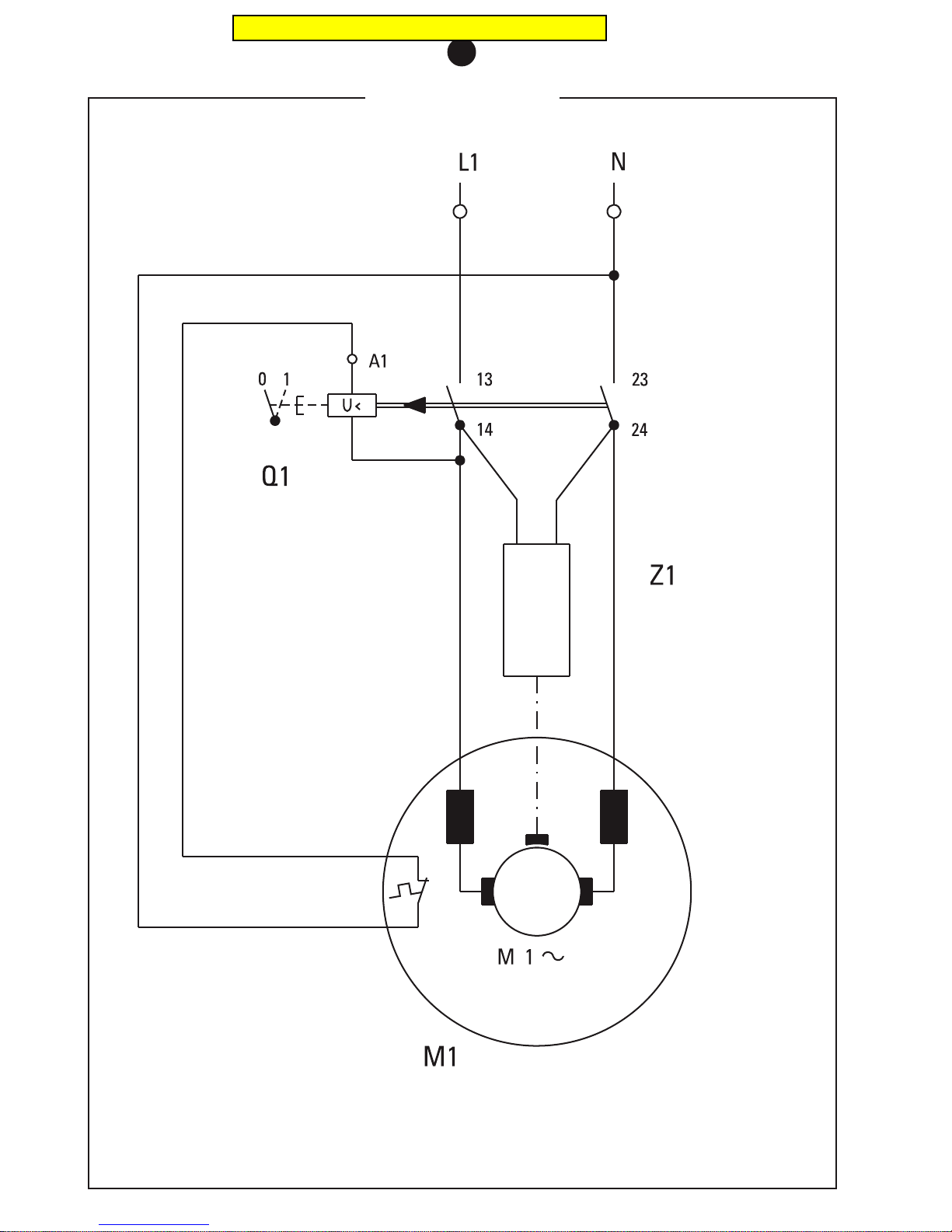
CIRCUIT DIAGRAM
10
Switch
Interference-free
capacitor
Motor 1.35 KW
230 V / 50 CPS
110-120 V / 60 CPS
Pricing in this catalog is outdated
Page 30
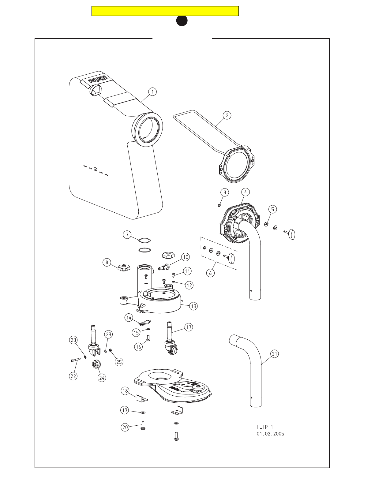
SPARE PARTS
11
Pricing in this catalog is outdated
Page 31

SPARE PARTS
11
Item Part no. Description
320.00.80.100 Dust bag, complete
1 320.00.86.105 Dust bag
2 320.00.82.100 Fixing plate with bracket
3 000.25.11.752 Retaining disc
4 320.14.00.100 Pipe socket, complete
5 000.10.10.055 Washer
6 000.25.11.433 Locking pin
7 000.11.40.901 O-ring
8 320.05.11.205 Star grip (locknut)
10 000.20.15.005 Stop bolt
11 7500.1005.012 Screw
12 0125.1005.000 Washer
13 320.08.10.100 Fan housing complete
14 320.08.03.100 Belt tightener plate
15 0125.1006.000 Washer
16 7985.1006.816 Screw
17 320.05.00.200 Guide roller, complete
18 320.01.09.100 Guide angle
19 0125.1008.000 Washer
20 7985.1008.825 Screw
21 320.14.92.100 Pipe socket for vacuum cleaner connection, 38 + 40 mm outside diameter
22 0912.1005.035 Screw
23 0125.1005.000 Washer
24 320.05.09.305 Wheel
25 0980.1005.000 Nut
Pricing in this catalog is outdated
Page 32
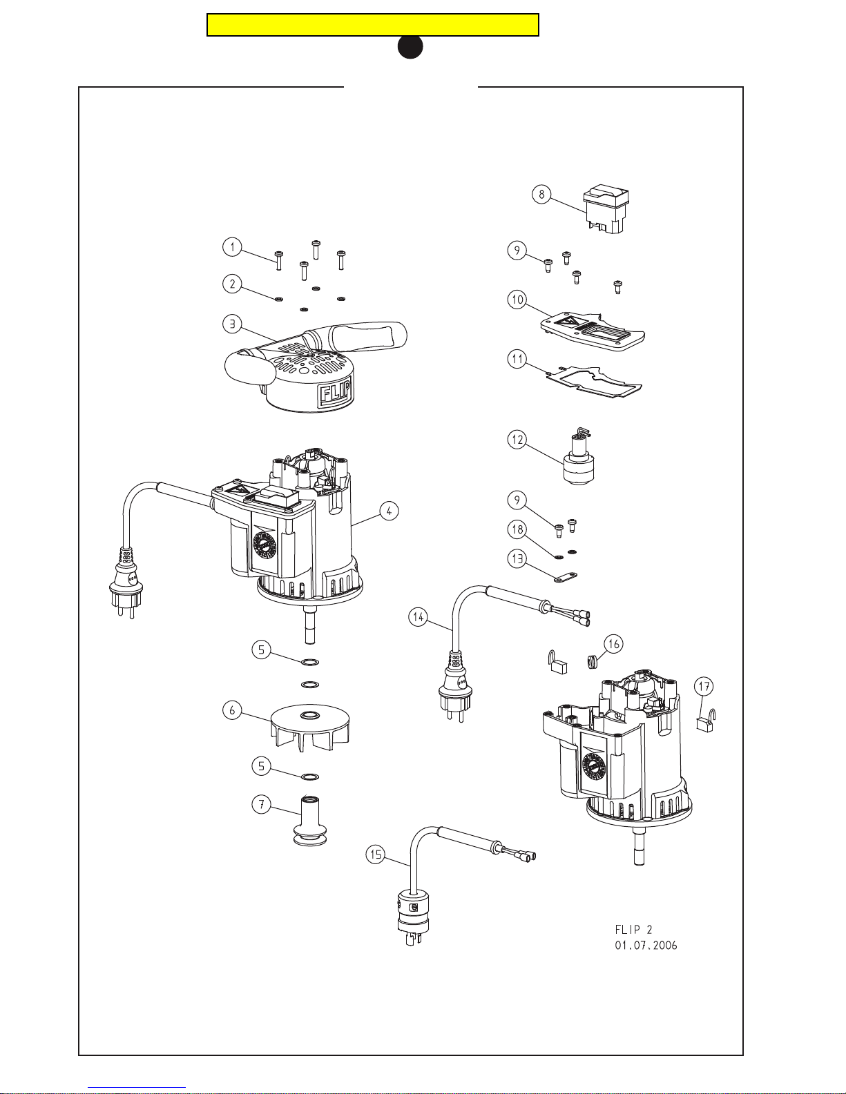
SPARE PARTS
11
Pricing in this catalog is outdated
Page 33

SPARE PARTS
11
Item Part no. Description
1 7500.1005.020 Screw
2 0127.1005.000 Spring washer
3 320.20.10.105 Handle
4 320.65.00.100 Universal motor, 230 V / 50 + 60 CPS
322.65.00.100 Universal motor, 110 V / 50 + 60 CPS, USA
5 0988.0016.005 Washer
6 320.10.10.100 Fan wheel
7 320.65.06.100 Motor belt pulley
8 000.65.60.256 Switch, 230 V / 50 + 60 CPS
000.65.60.156 Switch, 110 V / 50 + 60 CPS
9 7500.1005.012 Screw
10 320.65.47.100 Cover switchbox with sealing
11 320.65.48.105 Sealing
12 320.65.30.100 Interference-free capacitor, complete
13 320.65.59.100 Latch fastener
14 000.65.42.151 Motor cable 2 x 1.5 mm²
15 000.65.42.153 Motor cable 2 x 1.5 mm², USA
16 000.63.12.071 Rubber tube
17 000.65.84.012 Carbon brush
18 0125.1005.000 Washer
Pricing in this catalog is outdated
Page 34
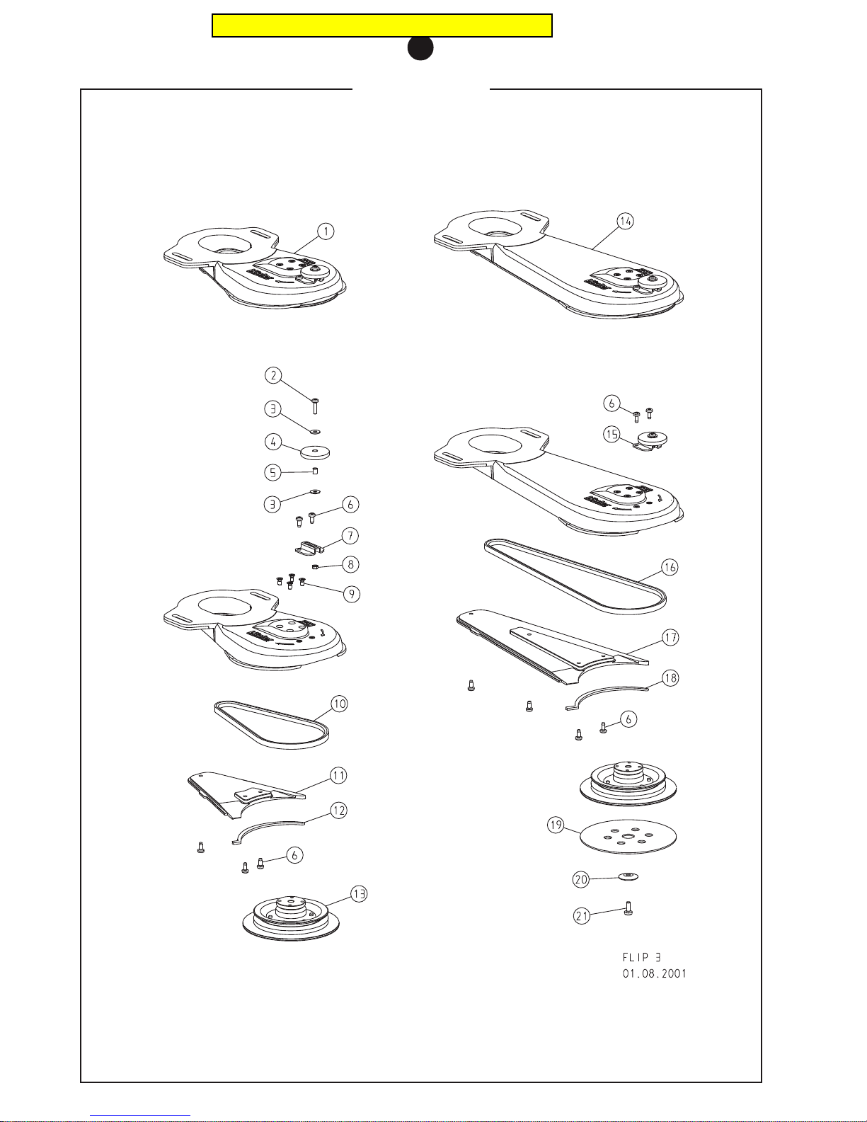
SPARE PARTS
11
Pricing in this catalog is outdated
Page 35

SPARE PARTS
11
Item Part no. Description
1 320.01.00.100 Attachment short, complete
2 7500.1005.020 Screw
3 9021.1005.000 Washer
4 320.60.02.100 Wall-protecting roller
5 000.43.15.052 Bush
6 7500.1005.012 Screw
7 320.60.01.100 Bracket
8 0934.1005.000 Nut
9 0965.1005.810 Screw
10 000.71.51.053 V-belt 10 x 530
11 320.01.03.100 Attachment cover short, complete
12 320.01.51.105 Seal, attachment cover short
13 320.01.91.100 Steel sanding plate, complete
14 330.01.00.100 Attachment long, complete
15 320.60.00.100 Wall-protecting roller with bracket
16 000.71.51.085 V-belt 10 x 850
17 330.01.03.100 Attachment cover long, complete
18 330.01.51.105 Seal, attachment cover long
19 350.03.35.205 Velcro disc 150 mm
20 320.02.05.100 Paper tensioning disc
21 7985.1006.816 Screw
Pricing in this catalog is outdated
Page 36
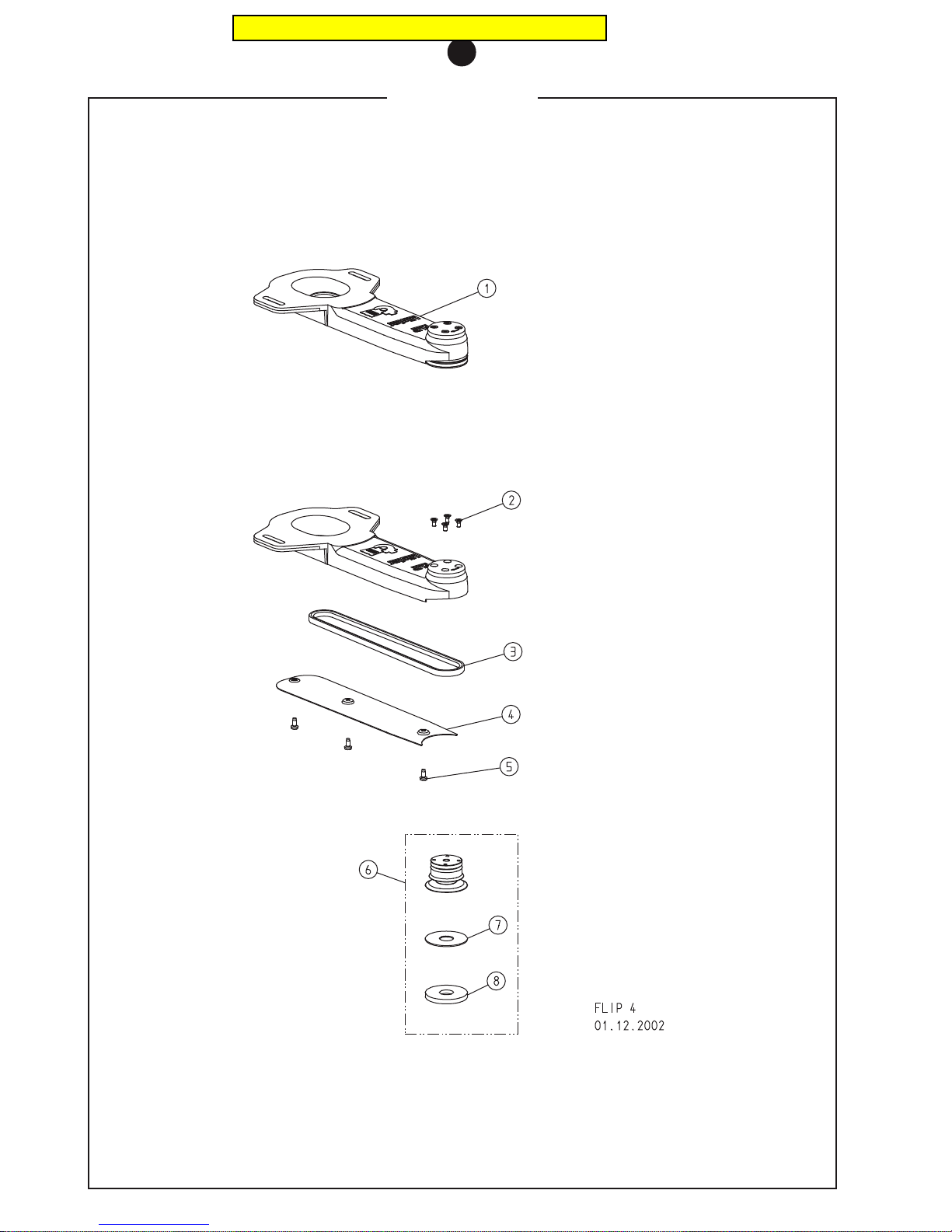
SPARE PARTS
11
Pricing in this catalog is outdated
Page 37
SPARE PARTS
11
Item Part no. Description
1 335.01.00.100 Corner attachment FLIP, complete
2 0965.1005.810 Screw
3 000.71.24.065 V-belt 10 x 650
4 335.01.02.100 Cover, corner attachment
5 7500.1005.012 Screw
6 335.01.91.100 Steel sanding plate for corner attachment, complete
7 335.02.12.105 Velcro disc, self-adhesive
8 335.02.13.105 Velcro ring, flexible
Pricing in this catalog is outdated
Page 38
SPARE PARTS
11
Pricing in this catalog is outdated
Page 39

SPARE PARTS
11
Item Part no. Description
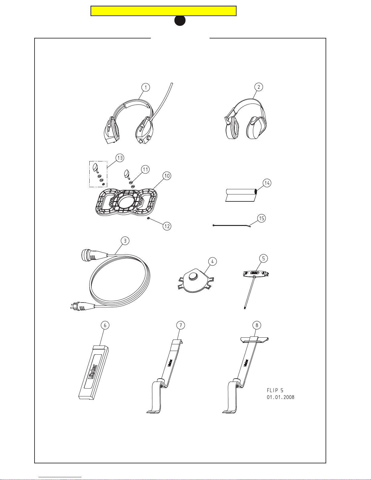
1 000.01.10.011 Foldable earmuff type MUSIMAFF
2 000.01.10.021 Foldable earmuff type POCKET
3 000.65.53.151 Extension cable 3 x 1.5 mm², 10 m
4 000.01.20.010 Protective mask P3
5 000.91.40.001 Universal spanner
6 701.10.00.100 Impact tool
7 702.00.00.200 Parquet layer tool, small
8 703.00.00.200 Parquet layer tool, broad
10 320.00.70.100 Emptying fixture, complete
11 000.10.10.055 Washer
12 000.25.11.752 Retaining disc
13 000.25.11.433 Locking pin
14 00.000.25.570 Waste bag
15 000.61.10.363 Cable binder
Pricing in this catalog is outdated
Page 40

NOTICE
Pricing in this catalog is outdated
Page 41

NOTICE
Pricing in this catalog is outdated
Page 42

NOTICE
Pricing in this catalog is outdated
Page 43

SERVICE PASSPORT
12
SERVICE PASSPORT
On the back of these operating instructions, please enter the serial number and the year of construction of your machine (see
rating plate). Otherwise your service passport will not be valid.
Be sure that any kind of maintenance work is certified here by your dealers company.
Date of test
and service: ___________________
Signature and stamp
Date of test
and service: ___________________
Signature and stamp
Date of test
and service: ___________________
Signature and stamp
Date of test
and service: ___________________
Signature and stamp
Date of test
and service: ___________________
Signature and stamp
Date of test
and service: ___________________
Signature and stamp
Date of test
and service: ___________________
Signature and stamp
Date of test
and service: ___________________
Signature and stamp
Date of test
and service: ___________________
Signature and stamp
Date of test
and service: ___________________
Signature and stamp
Date of test
and service: ___________________
Signature and stamp
Date of test
and service: ___________________
Signature and stamp
Date of test
and service: ___________________
Signature and stamp
Date of test
and service: ___________________
Signature and stamp
Date of test
and service: ___________________
Signature and stamp
Pricing in this catalog is outdated
Page 44
DECLARATION OF CONFORMITY
13
Declaration of conformity
according to EC regulations
98/37/EC from 22.06.1998
Low voltage (73/23/EEC, last changed through 93/68/EEC from 22.06.1993)
Electromagnetic compatibility (89/336/EEC, last changed through 93/68/EEC from 22.06.1993)
The design of the edge-, corner- and stair-sanding machine LÄGLER FLIP, for serial no. please see rating plate, is
developed, constructed and built according to the above mentioned regulations.
The following harmonized specifications are used:
DIN EN 292 Part 1 and Part 2, Safety of machines, equipment and systems
DIN EN 60 204.1, Electrical equipment for industrial machinery
EN 55014-1, Electro-magnetic Compatibility: Radiated Interference – Product Family Standard
EN 55014-2, Electro-magnetic Compatibility: Resistance to Interference – Product Family Standard
EN 61000-3-2, Electro-magnetic Compatibility: Limits for Harmonic Frequency Currents
EN 61000-3-3, Electro-magnetic Compatibility: Limits for Voltage Variations and
Flicker in Low Voltage Networks for Equipment with an Input Current of
< 16 A per Conductor
Following documents are existing:
• Master plan of the machine including electrical plans
• Complete specified plans to check accord of the machine with major safety rules
• List of regulations, specifications and EEC rules used for the design of the machine
• Description of the solutions to avoid dangers for the operators and environment
• One sample of the owner’s manual
Eugen Lägler GmbH · Maschinenbau
Industriegebiet Kappelrain Dipl.-Ing. (FH) Volker Wörner, Construction
D-74363 Güglingen-Frauenzimmern Eugen Lägler GmbH, Maschinenbau
Phone: +49 - 7135 - 98 90-0 · Fax: +49 - 7135 - 98 90-98 Güglingen-Frauenzimmern,
E-Mail: [email protected] · http://www.laegler.com 01.01.2008
FLIP
Serial No: __________________________________
Built in: ____________________________________
CAN
GB
NZ
USA
AUS
IRL
Pricing in this catalog is outdated
 Loading...