

La Germania LUEP51-90-S User Instructions
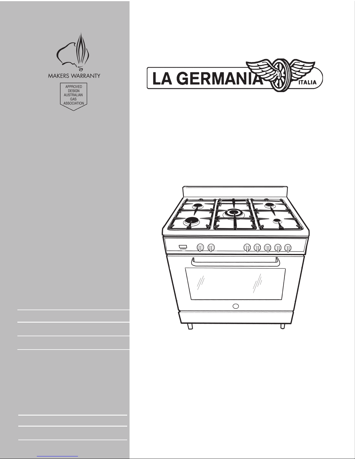
MODEL
LUEP51-90-S
UPRIGHT COOKER
This cooker is approved for use with Natural and Propane gases
Leave instructions with the owner
Installation instructions
User instructions
LUEP51-90-S

2
Contents
Contents 2-3
Important information 4-5
❍ Introducing your new cooker
❍ Notes on disposal
❍ Before connecting your new cooker
❍ Safety considerations
Installation instructions 6-7
❍ Statutory regulations
❍ Gas supply
❍ Electrical supply
❍ Instructions
❍ Vertical clearances
❍ Overhead clearances
❍ Side clearances to vertical surface
❍ Overall dimensions
Electric & gas connection 8-9
❍ Electrical connection
❍ Gas regulator
❍ If using a flexible connection
❍ If using a copper connection
❍ Gas inlet position - Nat Gas & LP Gas
❍ Gas inlet with different leg heights
❍ Energy consumption
❍ Test the operation of the cooker before leaving
❍ Warranty warning
❍ For service to this appliance
Support legs 10
❍ Method of fixing screw-in type leg
❍ Method of fixing push-on type leg
❍ Height adjustment of legs
Anti-tilt restraint 11
Upstand installation 12
Cooktop burner operation 13-14
❍ Control panel lay-out
❍ First time use
❍ Cooktop burner operation
❍ Cooktop burner adjustment
❍ Energy consumption
❍ Ventilation
❍ Use of cooktop burners
Oven/grill operation 15-17
❍ Accessories
❍ First time use
❍ Cooling fan operation
❍ Thermostat and function selector control knobs
❍ Oven and grill operation
❍ Oven functions
❍ Switching the oven ON
❍ Grilling (door closed)
❍ Conventional grilling
Data plate -Nat Gas
Data plate - LP Gas

3
❍ Fan grilling
❍ Shelf positions
Description of oven functions 18-20
❍ Oven light
❍ Conventional cooking
❍ Upper element
❍ Lower element
❍ Radiant grilling
❍ Fan grilling
❍ Fan forced cooking
❍ Defrosting
Oven cooking tips 20
Electronic control functions 21-22
❍ Setting time of day
❍ Oven will not switch on/to clear a program
❍ Manual operation
❍ Manual operation with timer
❍ Semi-automatic operation with end cooking
❍ Automatic operation with end cooking
❍ To clear a program
Cooking chart 23
Trouble shooting chart 24-25
Cleaning 26-27
❍ Cleaning hob
❍ Cleaning oven interior
❍ Cleaning oven shelf supports
❍ Cleaning oven glass door
❍ Replacing the oven light
Service information 28-35
❍ To remove glass lid (for cookers fitted with a glass lid)
❍ Access to under hob area
❍ To replace gas control valves or gas manifold
❍ To replace thermostat
❍ To remove side panels
❍ To replace the function selector control
❍ To replace electronic control box
❍ To replace cooktop burner electronic spark electrode
❍ To replace the under hob cooling fan
❍ To remove oven door
❍ To replace oven door inner glass panel
❍ To replace oven door outer glass panel
❍ To replace oven door hinges
❍ To replace oven fan
❍ To replace the electronic programmer
❍ To replace element from around the oven fan
❍ To replace top element
❍ To replace bottom element
❍ Final check
❍ Wiring diagrams
❍ Data plates - Nat Gas & LP Gas

4
Important information
Introducing your new cooker
We thank you and congratulate you on your choice.
This carefully designed product, manufactured with the highest
quality materials, has been carefully tested to satisfy all your
cooking demands.
We therefore request that you read and follow these easy
instructions which will allow you to obtain excellent results right
from the start.
This cooker is fitted with a gas cooktop featuring ‘one touch’
electronic ignition, flame failure safety cut-off to all cooktop
burners and a cooling fan. The programmable multi-function
electric oven contains a circulation fan, self cleaning oven linings
and a triple glazed oven door. The cooker is fitted either with
an upstand or a glass lid.
The cooker’s data plate is accessible even with the cooker fully
installed. It is positioned on the inside of the oven door, centre
bottom. A copy of the data plate is also reproduced on page
35 of this booklet. Always quote the details from it to identify
the appliance when ordering spare parts or requesting a service.
Notes on disposal
❍ Old appliances still have some residual value. An
environmentally friendly method of disposal will ensure that
valuable raw materials can be recovered and used again.
❍ Before you dispose of your old appliance, make sure that it
has been rendered inoperable.
❍ Your new cooker was protected by suitable packaging while
it was on its way to you. All materials used for this purpose
are environmentally friendly and suitable for recycling.
Please make a contribution to protecting the environment
by disposing of the packaging appropriately.
Before connecting your new cooker
❍ Before using your new cooker, please read these ‘Instructions
for Use’ carefully. They contain important information
concerning your personal safety as well as use and care of
the oven.
❍ Please keep the operating and installation instructions in a
safe place; this important documentation may also be of
use to a possible subsequent owner.
❍ Do not use the cooker if it is damaged in any way.
❍ Installation and connection of the cooker should be
performed according to the instructions and connection
diagram provided, and should be entrusted to a licensed

5
specialist. In the event of a damage that occurs as a result of
improper connection, the warranty will be void.
❍ Our appliances meet the applicable safety regulations for
electrical appliances, Repairs may be performed only by
customer service engineers trained by the manufacturer.
Inexpert repairs may entail serious injury to you, the user.
Safety considerations
❍ Never leave the appliance unattended when cooking with fat
or oil. It could ignite if overheated.
❍ In case of a defect, switch off at the mains.
❍ Do not clean the oven with steam or high pressure cleaners.
❍ Ensure that the power cord does not get caught in the hot
oven door. The plastic insulation could melt.
❍ Do not use loose greaseproof paper in the oven (e.g. when
heating the oven). The paper could be drawn to the fan and
damage the fan and the element.
❍ Do not insert a baking sheet or aluminium foil sheet at the
bottom of the oven. A heat build-up could result and cooking
times and temperatures could change or enamel could be
damaged.
❍ Do not pour water on the hot oven floor. Damage to enamel
could result.
❍ Always place a baking tray below a roast to prevent juices
from dripping on the oven lining.
❍ Do not place heavy items on the oven door when open as this
may result in damage to the door hinges.
❍ To ensure correct cooking the oven door must close properly.
Keep the door sealing surfaces clean at all times.
DO NOT SPRAY AEROSOLS IN THE VICINITY OF THIS
APPLIANCE WHILE IT IS IN OPERATION.
WHERE THIS APPLIANCE IS INSTALLED IN A MARINE CRAFT OR IN
CARAVANS, FOR SAFETY REASONS IT SHALL
NOT BE USED AS A
SPACE HEATER.
THIS APPLIANCE IS NOT INTENDED FOR USE BY YOUNG CHILDREN
OR INFIRM PERSONS WITHOUT SUPERVISION. YOUNG CHILDREN
SHOULD BE SUPERVISED TO ENSURE THEY DO NOT PLAY WITH THIS
APPLIANCE.
WARNING - ACCESSIBLE PARTS WILL BECOME HOT WHEN IN USE.
TO AVOID BURNS OR SCALDS CHILDREN SHOULD BE KEPT AWAY.

6
Statutory regulations
This appliance shall be installed in accordance with the
manufacturer’s installation instructions, local gas fitting
regulations, municipal building codes, electrical wiring
regulations, and AS 5601 the Australian Standard for gas
installations. Refer also AS 5601 for gas pipe sizing tables.
Gas supply
Check that the data plate shows the appliance is suitable for the
available gas supply. The data plate is located on the inside of
the warming compartment drop down door. A copy of the data
plate is also reproduced on page 35 of this booklet.
Electrical supply
This cooker require connection to a 15 Amp wall socket.
Instructions
1. The model number and the type of appliance, gas pressure
and gas type are found on the inside centre front of the oven
warming compartment drop-down door.
2. The appliance requires connection to a 240 V, 50 Hz
electric supply. The power point must be installed by an authorized person.
3. Before commencing any work, make sure that the power
point switches are turned off and the three in plug is removed.
4. If the appliance cannot be adjusted to perform correctly
contact Sampford & Staff or the local gas utility. For service
contact telephone number refer page 9.
5. Instruct the user in the operation of the appliance before
leaving.
Vertical clearances:-
The cooker shall be installed so that a vertical clearance of at
least 600 mm is maintained between its burners and any
combustible material and, where this is not practicable, the
underside of any combustible material less than 600 mm above
the burner shall be protected by noncombustible millboard at
least 6 mm thick which is covered with sheet metal not less than
0.4 mm thick, or shall be protected by an equivalent material,
extending at least 225 mm beyond the sides of the cooker.
Overhead clearances:-
Range hoods and exhaust fans shall be installed in accordance
with the manufacturer’s instructions. However, in no case shall
the clearance between the top of the highest burner of the
cooking appliance and the underside of a range hood be less
Installation instructions
7
than 600mm, or an overhead exhaust fan, 750 mm.
Side clearances to vertical surface:-
If the distance measured from the periphery of the nearest burner
to any vertical combustible surface, is less than 200 mm, the
surface shall be protected in accordance with clause 5.12.1.1
and 5.12.1.2 of AS 5601.
Make sure the minimum clearances to combustible materials are
maintained during the installation including adequate space for
the operation and servicing of the cooker.
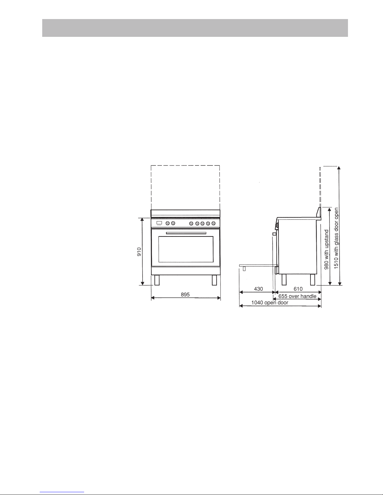
Overall dimensions (with legs adjusted to 180mm)
Height over hob: 910 mm
Height over upstand: 980 mm
Height over lid: 1510 mm
Width: 895 mm
Depth: (incl. oven door
handle & knobs): 655 mm
Depth: (flush with oven door): 610 mm
Note:
For stainless steel cookers fitted with an upstand an optional
glass lid is available. Part no: LL01-90-S.
For height limitations use dimensions with lid as shown in
drawing.
8
Electrical connection
The electric lead and plug are for connection onto a 15 Amp
socket. A 15 Amp socket is to be within 1 m of the appliance.
The lead is situated at the left hand side of the cooker.
Gas regulator
The gas connection is via 1/2” compression. Connect the cooker
to the gas supply and check for gas soundness.
If using a flexible connection
This appliance is approved for connection by a CLASS B hose.
Connection is in compliance with AS 5601, clause 5.12.1.8.
If using a copper connection
To allow cooker to be moved forward for service make a loop in
the copper tube before connecting onto regulator.
Gas connection
The cooker must connected to the gas supply with upstream
connection of an isolation valve in accordance with the
respectively valid regulations. We recommend that the isolation
valve be fitted prior to the cooker to enable isolation of the cooker
from gas supply. The valve must be easily accessible at all times.
To find out the factory set gas type, see label at rear of cooker.
The gas connection via 1/2” compression. Connect the cooker
to the gas supply and check for gas soundness. NEVER use a
naked flame to check for leaks.
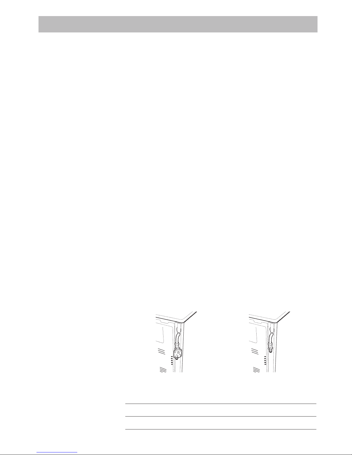
Gas inlet position- Nat gas Gas inlet position LP Gas
From RH rear side: 35 mm¢ From RH rear side: 35mm¢
Up from floor: 600 mm¢ Up from floor: 685mm¢
Gas inlet with different leg heights - mm
Min NG: 585 LP: 670
Ref NG: 600 LP: 685
Max NG: 620 LP: 705
Electric & gas connection
9
Energy consumption
Burners Gas type Pressure (kPa) Injector (mm) Mj/hr Watts
Small Natural 1.0 0.90 3.85 -
LPG 2.75 0.54 3.25 -
Medium Natural 1.0 1.18 7.12 -
(x2) LPG 2.75 0.70 5.75 -
Large Natural 1.0 1.55 12.5 -
LPG 2.75 0.92 11.25 -
Wok Natural 1.0 1.65 13.1 -
LPG 2.75 0.95 13.1 -
Oven/Grill 3000 W
Test the operation of the cooker before leaving
Note: These burners have no aeration adjustment.
Check correct operation of the ignition system and operation of
burners individually and in combination. Burner flames should
be clear blue, with no yellow tipping. If the burners show any
abnormality check that burner heads are correctly located. If
satisfactory performance cannot be obtained, contact Sampford
& Staff or the local gas utility. For service contact number refer
below.
Important
Before leaving instruct the owner in the use of the cooker.
Warranty warning
It should be expressly noted that we cannot accept any liability
for direct or indirect damage caused by wrong connection or
improper installation. When being repaired, the appliance must
always be disconnected from the mains supply; if required, notify
our customer service.
For service to this appliance
For service to this appliance please contact:
Sampford & Staff P/L
52 - 70 Sparks Avenue
Fairfield, Vic, 3078
Phone: 1300 727 421
Fax: 1300 727 425
Email: service@sampford.com.au
This appliance is imported
and distributed by:

10
The cooker is suppllied with four support legs. The legs are fitted
to the cooker with two alternative methods of fixing, either screwin type legs or push-on type legs.
Method of fixing screw-in type legs
Before fitting the legs remove the four transit supports. (One for
each corner). 4 support legs are supplied separately and are
fitted on location to the four corners of the lower support frame.
Method of fixing push-on type legs
Transit supports are left in situe. Each leg is
pushed firmly over a transit support.
Height adjustment of legs
Each leg is adjusted by screwing the lower
section in or out as required for fitting to a
900mm standard bench height. For lower
bench tops adjust height as
required. The adjustment range
for the leg is 150 - 185mm.
With the legs adjusted to a
height of 180mm the cooker
hob is located 10mm above the
horizontal cumbustible surface,
ref. AS 5601, fig 5.1
If the legs are not used and the cooker is mounted onto a plinth,
fit transit legs to allow for clearance.
Support legs
11
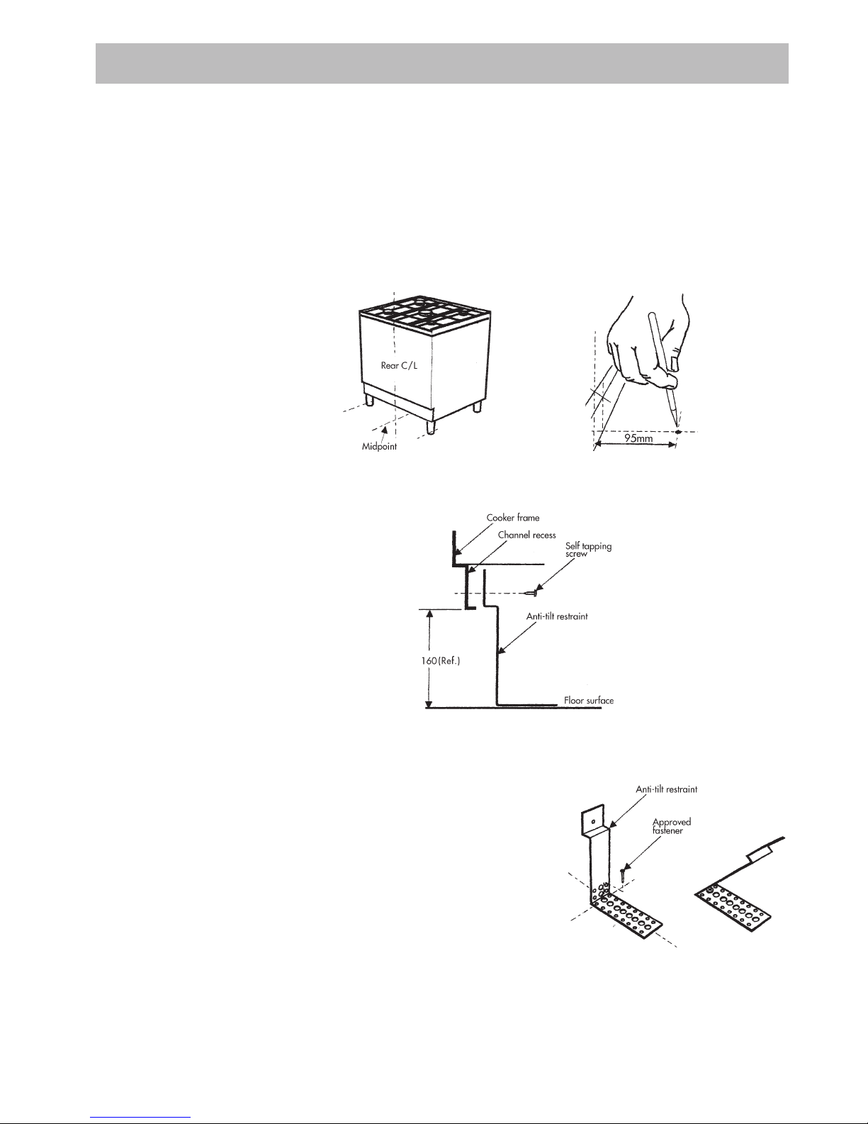
Once legs are adjusted to the correct height, fit the anti-tilt
restraint bracket.
1. Locate cooker in desired position and mark rear leg
positions.
2. Remove cooker and locate the mid point of the cooker at the
rear and on the floor, measure out from the wall 95mm to
mark the position of the fixing hole.
3. Measure height under channel recess to floor.
4. Bend anti-tilt restraint bracket (supplied) at 90° as measured.
5. Fix restraint bracket to floor
at position marked. Use the
hole closest to the bend for
fixing.
Note: For concrete floors, an
anchor is provided. For
other construction, use a
suitable fastener.
Bend bracket forward to
clear cooker base.
6. Relocate the cooker into the correct position and from the
underside front, bend anti-tilt bracket up and into channel
recess at cooker base. Fix into position with self tapping
screw provided.
Anti-tilt restraint
 Loading...