


La germania AMN855GXV User Manual

INSTALLATION, MAINTENAN CE
AND USE INSTR UCTIONS FOR
FREE-STANDING CO OKERS
90x60 cm
pag.2
NOTICE D’INS TALLATIO N, D’ENTRETIEN
ET MODE D’EMPLOI
DE LA CUISINI E RE A GAZ
90x60cm
pag.12
3100062

2
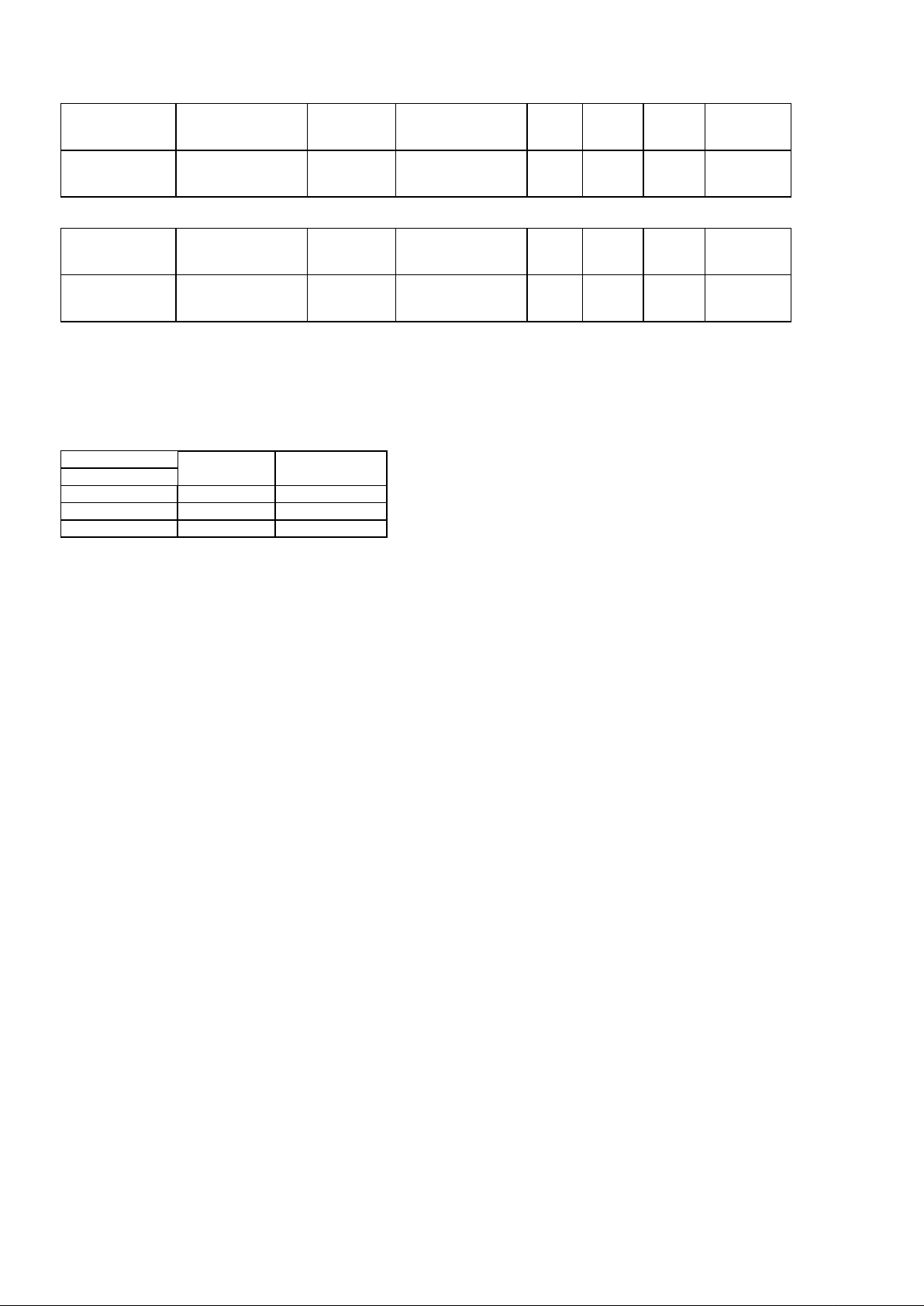
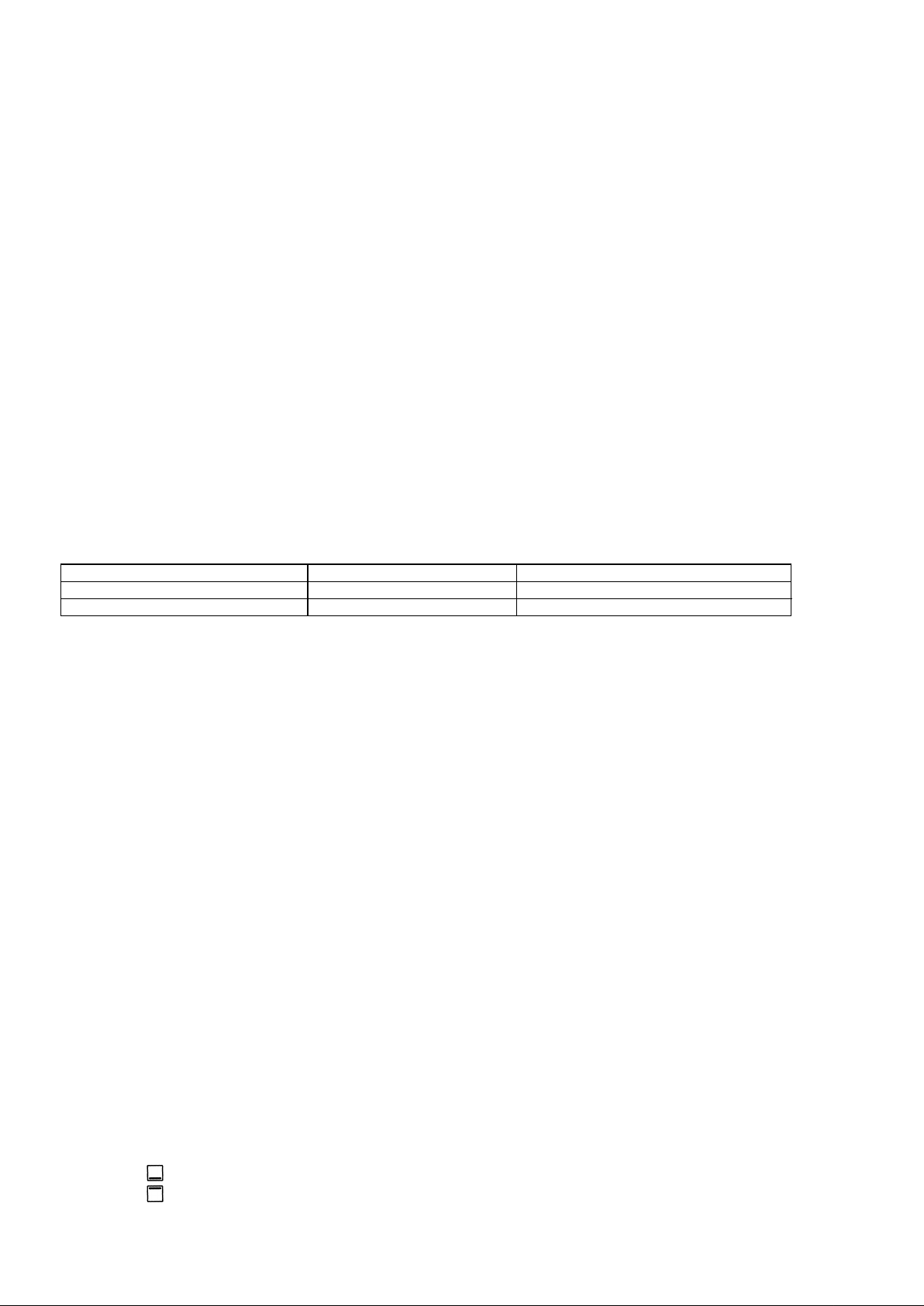
INSTALLATION, MAINTENANCE AND USE INSTRUCTIONS FOR
Burner
Types of gas
Pressure
Nozzle diameter
Rater capacity
mbar
1/100 mm.
g/h
l/h
kW
kcal/h
Auxiliary
Natural G20
20
72
-
95 1 860
Butane G30
30
50
73 - 1
860
Propane G31
37
50
71 - 1
860
Semi-rapid
Natural G20
20
97
-
167
1,75
1505
Butane G30
30
65
127 - 1,75
1505
Propane G31
37
65
125 - 1,75
1505
Rapid
Natural G20
20
115
-
286 3 2580
Butane G30
30
85
218 - 3
2580
Propane G31
37
85
214 - 3
2580
Double
Natural G20
20
135
-
334
3,5
3010
Ring
Butane G30
30
95
254 - 3,5
3010
Propane G31
37
95
250 - 3,5
3010
READ THE INSTRUCTION BOOKLET BEFORE INSTALLING AND USING THE APPLIANCE.
The manufacturer will not be responsible for any damage to property or to persons caused by incorrect installation or
improper use of the appliance.
The manufacturer is not responsible for any inaccuracies, due to printing or transcription errors, contained in this booklet. In
addition, the appearance of the figures report ed is also purely indicative.
The manufacturer reserves the right to make changes to its products when considered necessary and useful, without affecting
the essential safety and operating characteristics.
THIS APPLIANCE HAS BEEN DESIGNED FOR NON-PROFESSIONAL DOMESTIC USE.
Before connecting the appliance to the gas network, make sure that the data on the label attached to the food warmer
drawer or on the back of the cooker are compatible with what is indicated for the gas distribution network.
A label attached to the last page of this handbook and in the food warmer drawer (or on the back) of the appliance
indicates the appliance adjustment conditions: type of gas and operating pressure.
IMPORTANT: This appliance must be installed in compliance with current national standards in force and used only in
a well-ventilated room.
WARNING: It should be recalled that the appliance utilises a threaded 1/2" gas cylindrical male fitting according to UNIISO 228-1.
To connect the appliance to the gas network with a flexible rubber hose, a supplemental hose nipple fitting is needed
(see Fig. 1) which is supplied with the appliance.
Before performing any maintenance operation, disconnect the appliance from the gas supply and electricity network.
REPLACING THE NOZZLES TO OPERATE WITH ANOTHER TYPE OF GAS:
Follow the instructions below to change the burner nozzles on the work surface:
1) Pull out the plug from the electric outlet to avoid any type of electric contact.
2) Remove the grids from the work surface (Fig. 2).
3) Remove the burners (Fig. 2).
4) Unscrew the nozzles using a 7 mm spanner, and replace them (Fig. 3) with those needed for the new type of gas according
to what is indicated in Table 1.
Follow the instructions below to change the oven burner nozzle:
1) Remove the oven level (Fig. 4-5).
2) Loosen the screw V and pull out the burner from the support being careful not to damage the ignition plug and the
thermocouple (Fig. 6).
3) Unscrew the nozzle R (Fig. 6) using a 10 mm spanner and replace it with the nozzle needed for the new type of gas
according to what is indicated in Table 2.
Follow the instructions below to change the grill burner nozzle:
1) Loosen the screw at the end of the grill burner and pull out the burner from the support being careful not to damage the
ignition plug and the thermocouple (Fig. 7).
2) Unscrew the nozzle C (Fig. 7) using a 7 mm spanner and replace it with the nozzle needed for the new type of gas according
to what is indicated in Table 2 or in Table 3 .
WARNING: After completing the above-mentioned replacements, the technician must adjust the burners, as described
in the paragraph below, seal any adjustment and pre-adjustment devices and apply the label on the
appliance, to replace the existing one, corresponding to the new gas adjustment. This label is contained in
the spare nozzle bag.
Table 1
FREE-STANDING COOKERS 60x60 cm
INSTALLER TECHNICAL MANUAL
APPLIANCE GAS CONNECTION
ADAPTATION TO DIFFERENT TYPES OF GAS
3
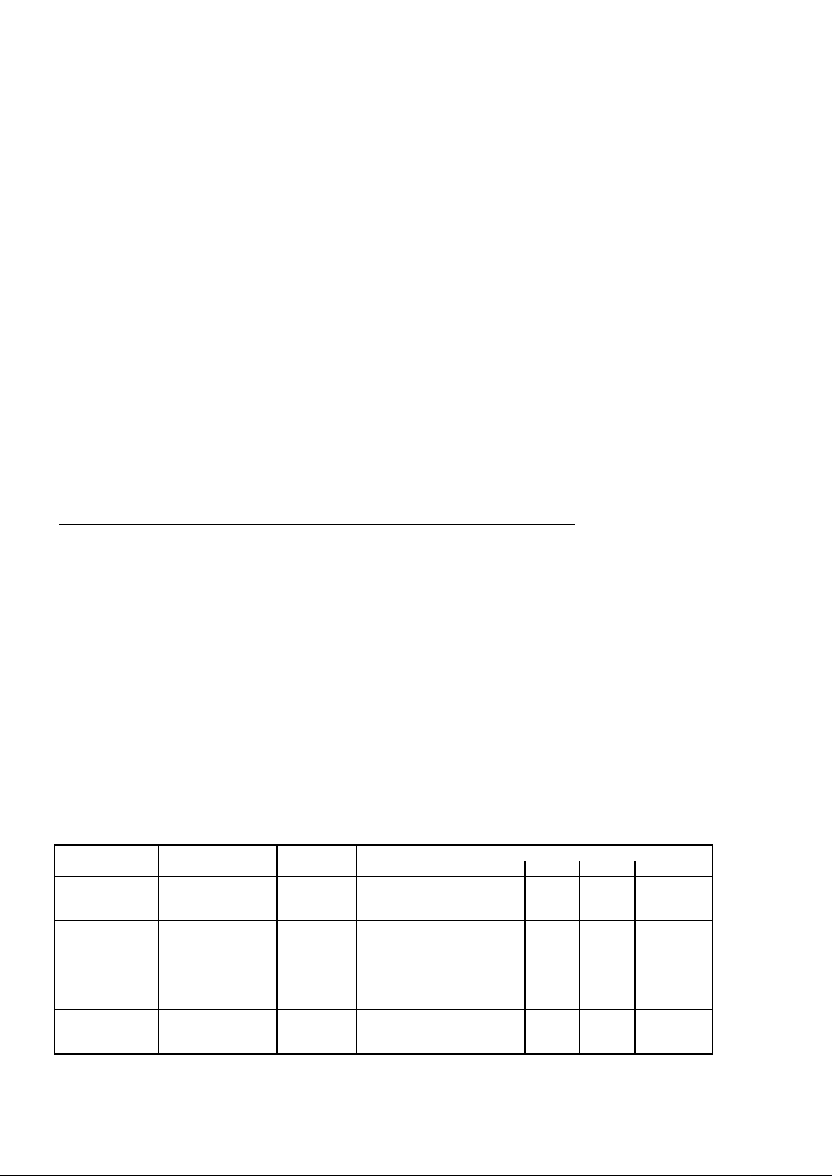
Table 2 (model with gas oven and gas gr ill with double controls)
Oven
Natural G20
20
102
-
191 2 1720
Butane G30
30
70
145 - 2
1720
Propane G31
37
70
143 - 2
1720
Grill
Natural G20
20
88
-
143
1,5
1290
Butane G30
30
60
109 - 1,5
1290
Propane G31
37
60
107 - 1,5
1290
Oven
Natural G20
20
125
-
286 3 2580
Butane G30
30
85
218 - 3
2580
Propane G31
37
85
214 - 3
2580
Grill
Natural G20
20
96
-
172
1,8
1548
Butane G30
30
65
131 - 1,8
1548
Propane G31
37
65
128 - 1,8
1548
Burner
Oven
Grill
Type of Gas
(mm.)
(mm.)
Natural G 20
Fully open
Fully open
Butane G 30
Fully open
Fully open
Propane G31
Fully open
Fully open
Table 3 (model with gas oven and gas grill with single control, or gas oven and electric grill)
BURNER ADJUSTMENT
1)Primary air adjustment:
Oven burner adjustment: follow the instructions below to adjust the primary air for the over burner:
1) Remove the oven bottom.
2) Loosen the screw P and adjust the position X of the V enturi cone (Fig. 8) according to the measurements indicated in table 4.
Grill burner adjustment: to adjust the grill burner loosen screw P and adjust the position X of the Venturi cone (Fig. 9)
according to the measurements indicated in table 4.
TABLE N.4
2) Burner "MINIMUM" adjustment:
Work surface burner adjustment: follow the instructions below to adjust the work surface burner minimum:
1) Light the burner and set the knob to the MINIMUM position (small flame).
2) Remove the knob of the valve that is press fit on the rod of that valve.
3) If the cooker is not equipped with safety valves on the surface burners, insert a small slotted screwdriver into the hole on the
valve rod (Fig. 10) and turn the choke screw to the right or left until the burner flame is adjusted to minimum. If the cooker is
equipped with safety valves, the choke valve is not located in the rod hole, but on the valve body (see fig. 11).
4) Make sure that the flame does not go out when switching quickly from the MAXIMUM to the MINIMUM position.
Oven burner adjustment: follow the instructions below to adjust the minimum:
1) Light the burner setting the knob to the MAXIMUM position.
2) Close the oven door and operate the oven for at least 10 minutes.
3) Set the knob to the MINIMUM position (corresponding to 120°) and then remove it.
4) With a slotted screwdriver turn the choking screw (see figure 12) and, while observing the flame at the same time through the
cooker porthole, evaluate the consistency of the flame so it remains on when switching quickly from the MINIMUM to the
MAXIMUM position.
Grill burner adjustment: follow the instructions below to adjust the minimum:
1) Light the burner setting the knob to the MAXIMUM position.
2) Close the oven door and operate the oven for at least 10 minutes.
3) Set the knob to the MINIMUM position (small flame) and then remove it.
4) If the cooker is not equipped with safety valves on the surface burners, insert a small slotted screwdriver into the hole on the
valve rod (Fig. 10) and turn the choke screw to the right or left, while observing the flame at the same time through the cooker
porthole, evaluate the consistency of the flame so it remains on when switching quickly from the MINIMUM to the MAXIMUM
position. If the cooker is equipped with safety valves, the choke valve is not located in the rod hole, but on the valve body (see
figure 10).
WARNING: The above-mentioned adjustment should be made only with natural gas burners, while for those operating
with liquid gas the screw must be locked at the end in a clockwise direction.
WARNING: For the model with single grill burner, the grill burner always operates at maximum and therefore no
minimum adjustment is required.
APPLIANCE ELECTRIC CONNECTION:
The electric connection must comply with the current legal standards and regulations.
Before making the connection, check that:
- The system electrical rating and the current outlets are adequate for the maximum power output of the appliance (see the label
applied to the bottom of the casing).
- The outlet or the system is equipped with an efficient ground connection in accordance with the current legal standards and
regulations. The company will not be responsible for the non-compliance with these instructions.
When the connection to the power supply network is made using an outlet:
- If the power cord is supplied without a plug, apply a standard plug that is suitable for the load indicated on the label. Connect
the wires according to the diagram shown in FIG.13 and check that:
letter L (phase) = brown wire;
letter N (neutral) = blue wire;
ground symbol = green-y ellow wire;
4
- The power cord must be positioned so that an overtemperature of 75 K will not be reached at any point.
Burner
Dimension (mm)
Auxiliary
Ø 50
Semi-rapid
Ø 70
Rapid
Ø 95
Ultra-rapid
Ø 130
TIPE OF PLATE
DIMENSION
Electric hot plate
Ø 145
Electric hot plate
Ø 180
- Do not use reductions, adapters or splitters since they might cause false contacts and lead to dangerous overheating.
When the connection is made directly to the electric network:
- Insert an omnipolar circuit-breaker between the appliance and the network which is sized for the appliance load with a
minimum opening between the contacts of 3 mm.
- Remember that the ground wire must not be interrupted by the circuit-breaker.
- As an alternative, the electric connection can also be protected by a high-sensitivity residual current circuit-breaker.
- It is highly recommended to attach the special green-yellow ground wire to an efficient ground system.
APPLIANCE MAINTENANCE
REPLACING PARTS
Before performing any maintenance operation, disconnect the appliance from the gas supply and electricity network.
To replace parts such as knobs and burners, just remove them from the seats without disassembling any part of the cooker.
To replace parts such as nozzle supports, valves and electric components follow the procedure described in the burner
adjustment paragraph. To replace the valve or the gas thermostat, it is also necessary to disassemble the two rear gas train
brackets, loosening the 4 screws (2 per bracket) that attach it to the rest of the cooker and, unscrew the nuts that attach the
front burner valves to the control support, after removing all the knobs. To replace the gas or electric thermostat, also
disassemble the rear cooker guard, loosening the relative screws, to be able to pull out and reposition the thermostat bulb.
To replace the oven bulb, just unscrew the protection cap that projects out inside the oven.(fig.14)
WARNING: Before replacing the bulb, disconnect the appliance from the electric power supply.
USE AND MAINTENANCE MANUAL
GAS BURNER DIMENSION
ELECTRIC HOT PLATE DIMENSION
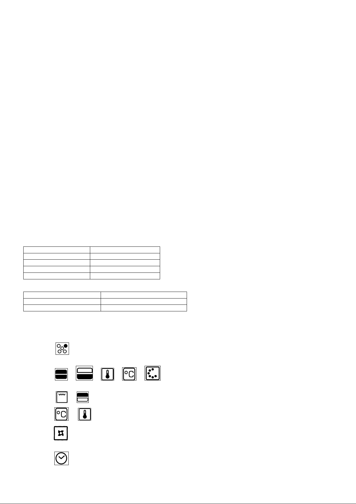
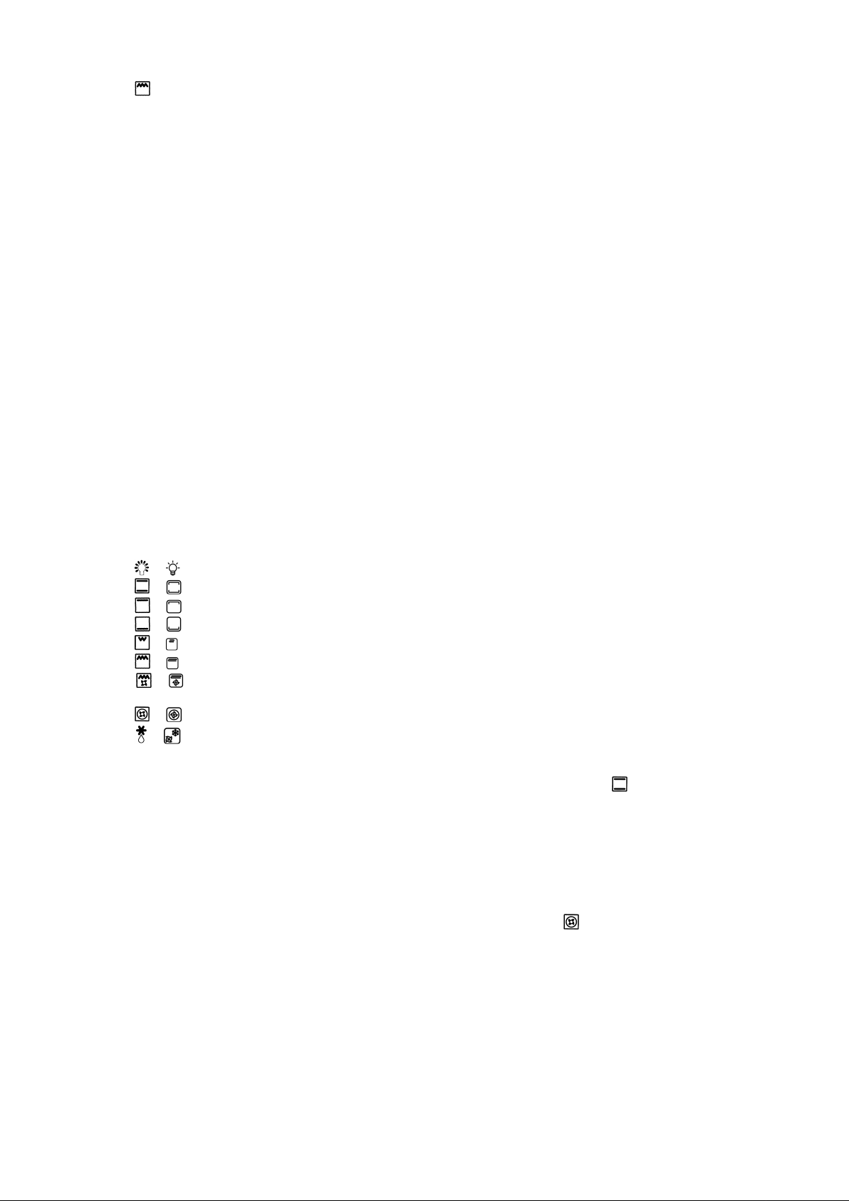
CONTROL PANEL DESCRIPTION
On the control panel, small symbols show the function of each knob or key. Here as follows are the several controls
that a cooker can have:
the symbol shows the disposition of burners on the worktop, the full dot identifies the burner in object (in this case the
rear burner on the right).
the symbol or or or or shows the running of any oven (gas oven, gas oven with gas grill, gas
oven with electric grill, static oven, 9 positions switch)
the symbol or shows the grill (gas grill, electric grill)
the symbol or shows the electric thermostat for electric fan oven
the symbol shows the oven fan working button as to allow the oven to operates with fan assisted gas. The fan operation
of the oven prevents the operation of the grill, which therefore cannot be used with the fan in action.
the symbol shows the minute minder
5
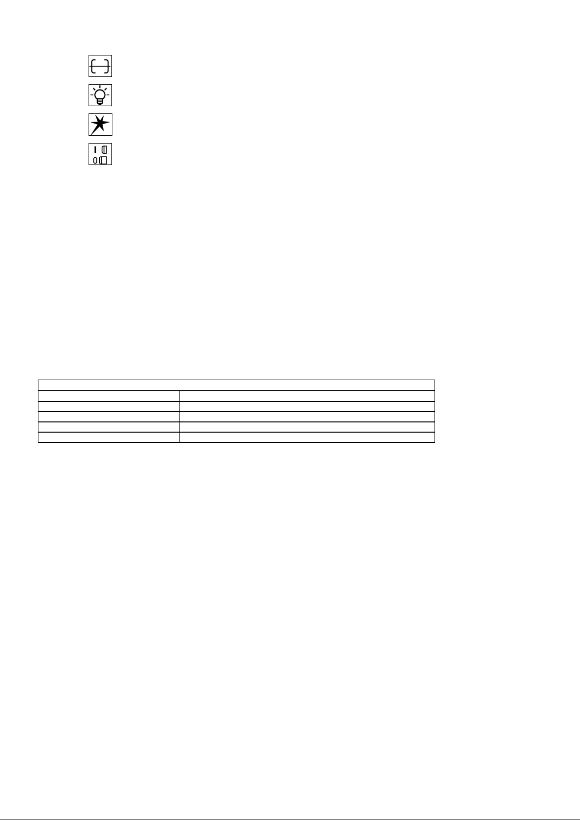
the symbol shows the operating key for the rotisserie (only gas oven)
TABLE N°5: Recommended pot diameters.
BURNER
Recommended POT DIAMETERS (cm.)
Auxiliary
12 – 14
Semi-rapid
14 – 26
Rapid
18 – 26
Double ring
22 – 26
the symbol shows the ignition key for the oven light (all except the electric fan oven)
the symbol shows the push-button for burner ignition
the symbol shows if keys are in position “on” or “off”
USING BURNERS
A diagram is etched on the control panel above each knob which indicates which burner corresponds to that knob. The burners
can be ignited in different ways depending on the type of appliance and its specific characteristics:
- Manual lighting (it is always possible even when the power is cut off): Turn the knob counterclockwise that corresponds
to the burner selected, setting it to the MAXIMUM position at the etched star (large flame Fig.17A-17B-17C) and place a lit
match up to the burner.
- Electric ignition:
Turn the knob counterclockwise that corresponds to the burner selected, setting it to the MAXIMUM position
(large flame Fig. 17A-17B-17C) and keep on pressing the knob in correspondence of the ignition symbol marked with a star (for
cookers equipped with ignition trough knob) or press the ignition button marked with a star and release it as soon as the burner
has ignited.
- Burner ignition equipped with safety device (thermocouple)(fig.16): Press and turn the knob counterclockwise that
corresponds to the burner selected, setting it to the MAXIMUM position at the etched star (large flame Fig. 17A-17B-17C), press
the knob and activate one of the above-mentioned ignition devices. Once ignited, keep pressing the knob for about 10 seconds
to allow the flame to heat the thermocouple. If the burner goes out after releasing the knob, repeat the entire operation.
Note: It is recommended not to try to ignite a burner if the relative flame cap is not in the correct position.
Tips for using burners correctly:
- Use suitable pots for each burner (see tab. 5 and Fig.19).
- When the liquid is boiling, turn the knob to the MINIMUM position (small flame Fig. 17A-17B-17C).
- Always use pots with a cover.
WARNING: Use flat-bottomed containers
WARNING: After cleaning, make sure head “B” and covers “A” are properly placed on their seat as figure 18A and not
off-center as in figure 18B
WARNING: If the power is cut off, the burners can be lit with matches. When cooking foods with oil and fat, which are
very flammable, the user should not leave the appliance unattended. If the appliance is equipped with a
glass cover, such a cover may break when heated. Turn off all burners before lowering the cover. Do not
use sprays near the appliance when it is being used.
When using the burners, make sure that the handles of the pots are correctly positioned. Keep children
away from the appliance. If equipped with a cover, before being closed, any food deposits should be
cleaned off the built-in surf ace.
NOTE: The use of a gas cooking appliance produces heat and humidity in the room where it is installed. Therefore,
proper aeration in the room is needed while ensuring that natural ventilation openings remain unobstructed.
Intensive and continuous use of the appliance may require additional aeration, for example by opening a
window, or more efficient aeration by increasing the power of the mechanical exhauster, if installed.
USING HOT PLATES
These plates are controlled by a switch with 6 settings (see Fig.20A-20B). The plates are turned on by turning the knob to the
desired position. The front panel of the appliance is etched with a mark indicating what plate corresponds to the knob. A light,
which is also installed on the control panel turns on, indicating that the plate is on.
How to use a hot plate:
When a hot plate is used for the first time or after a long period of inactivity, it is recommended to use it on position 1 for about
30 minutes to eliminate any humidity absorbed by the internal insulating material.
As example, we have included a table with the adjustments needed to ensure proper use of the hot plates.
WARNING: When a hot plate is used for the first time or after a long period of inactivity, it is
necessary to use it on position 1 for about 30 minutes to eliminate any humidity absorbed by the
insulating material.
6
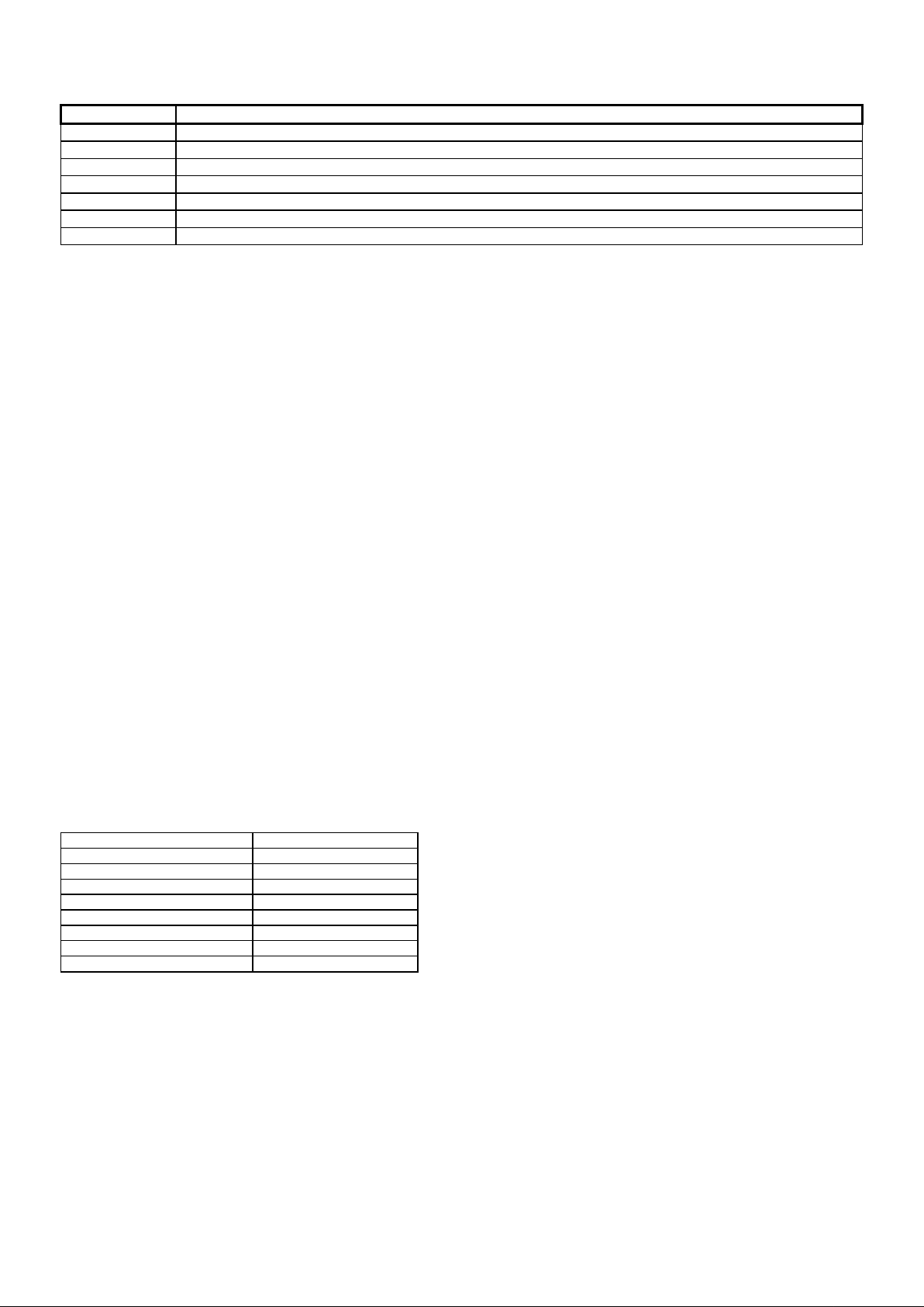
TABLE N°6
PLATE
POSSIBLE COOKING METHOD S
0
Plate off
1
To melt butter, chocolate, etc. - To heat small amounts of liquid
2
To heat larger quantities of liquid - To prepare creams and sauces that required extended cooking
3
To defrost foods, cook at boiling temperature
4
To cook roasts with delicate meat and fish
5
For meat roasts and steaks, for large pieces of boiled meat
6
To boil large quantities of water, for frying.
THERMOSTAT SETTING
TEMPERATURE °C
1
120°C
2
140°C
3
160°C
4
180°C
5
200°C
8
270°C
To ensure correct use, remember the following:
- Dry the bottom of the pot before placing it on the plate.
- Use pots with a flat and thick bottom (see Fig. 21).
- Never use pots that are smaller than the plate.
- Turn on the plate only after the pot has been placed on top.
- As soon as a crack appears on the surface of the hot plate, immediately turn off the appliance.
- If the appliance is equipped with a glass cover, it may break when heated.
- Turn off all the plates before closing the cover.
- After use, and to ensure good preservation, the plate should be treated with normal products for electric hot plates
that are available in the market so that the surface is always clean; this operation will prevent any corrosion (rust).
- After they are used, the plates remain hot for a long time; therefore, do not place the hands or other objects on the
plate to avoid burns.
- When using the burners, make sure that the handles of the pots are correctly positioned. Keep children away from the
appliance.
- When cooking foods with oil and fat, which are very flammable, the user should remain near the appliance.
WARNING: As soon as a crack appears on the surface of the hot plate, immediately turn off the appliance.
USING THE GAS OVEN (SINGLE CONTROL)
GAS OVEN:
All the gas oven cookers are equipped with a thermostat and safety device to adjust the cooking temperature. The oven
temperature is set by turning the knob counterclockwise to match the indicator with the temperature selected. The gas oven can
be combined with a gas grill or an electric grill. See the specific pages for use information.
FAN GAS OVEN:
Operating the fan of the oven by means of the appropriate switch situated on the control panel, the circulation of warm air
guarantees a uniform heat distribution. The preheating of the oven can be avoided. However for delicate baking, it is preferable
to warm the oven before introducing the baking-pan. The baking system with the fan convection changes in part the various
traditional baking notions. When roasting meat it is not necessary to turn the meat any more and for a roast on the spit, it is not
indispensable to use the spit-roaster, but is sufficient to put the meat directly on the grate.
With the use of the fan gas oven, the baking temperatures are slightly lower of about 10-15°C compared to those in use with the
traditional gas oven. The fan operation of the oven prevents the operation of the grill, which therefore cannot be used with the
fan in action.
The oven can also be used in a traditional way, (by not activating the fan) for foods requiring heat from the bottom, e.g. pizza.
WARNING: If the burner flames are extinguished accidentally, turn off the control knob and do not try to relight the
oven until after at least 1 minute.
TABLE N°7
6 225°C
7 245°C
The oven burner can be ignited in different ways:
- Manual lighting (it is always possible even when the power is cut off):
To light the oven, open the oven door and turn the knob so the no. 8 on the scale matches the indicator (fig.22A-22B-22C-22D).
At the same time put a lit match next to the ignition tube that is visible on the oven level (fig.23). Then press the thermostat knob
(this makes the gas start to flow) and keep it pressed, after the burner has been completely lit, for 10 seconds. Release the
knob and make sure that the burner remains on, otherwise repeat the operation.
- Electric ignition (only for the models equipped with this device):
In this case, first open the oven door, then press and turn the knob to the maximum temperature setting (number 8). Then press
the thermostat knob (models with ignition trough knob). Wait about 10 seconds after the burner has been completely lit and then
release the knob. Make sure that the burner remains on, otherwise repeat the operation. As for cookers without ignition trough
knob, press the thermostat knob and the key with the spark symbol, wait about 10 seconds after the burner has been
completely lit and then release the knob. Make sure that the burner remains on, otherwise repeat the operation.
The ignition device should not be used for more than 15 seconds. If after that period the burner still has not been lit, do
not use the device and open the door of the room or wait at least 60 seconds before trying to light the oven again.
7
WARNING: when trying to light the oven, the door must always be open. When using the oven, leave the cooker cover
POSITION OF OVEN KNOB
ONLY OVEN BURNER
OVEN BURNER+GRILL BURNER
1=MINIMUM
120°C
200°C
8=MAXIMUM
220°C
270°C
open to prevent it from overheating.
NOTICE: when using the oven for the first time it should be operated for 15-30 minutes at a temperature of about 250°
without cooking anything inside in order to eliminate any moisture and odours from the internal insulation.
During normal oven use, after lighting the burner and setting the desired temperature, wait about 15 minutes before putting in
any food to preheat the oven.The oven is equipped with 5 guides (FIG.24) at different heights which can be used to insert
shelves or the tray. To keep the oven as clean as possible it is recommended to cook meat on the tray or on the shelf that has
been inserted inside the tray.
USING THE GAS OVEN FOR MODEL WITH DOUBLE CONTROLS
GAS OVEN:
All the gas oven cookers are equipped with a thermostat and safety device to adjust the cooking temperature. The oven
temperature is set by turning the knob counterclockwise to match the indicator with the temperature selected. The gas oven can
be combined with a gas grill or an electric grill. See the specific pages for use information.
When the cooker model allows the combinated use of gas oven and gas grill, the oven inner temperature is adjustable within the
limit indicated in TABLE 8.
FAN GAS OVEN:
Operating the fan of the oven by means of the appropriate switch situated on the control panel, the circulation of warm air
guarantees a uniform heat distribution. The preheating of the oven can be avoided. However for delicate baking, it is preferable
to warm the oven before introducing the baking-pan. The baking system with the fan convection changes in part the various
traditional baking notions. When roasting meat it is not necessary to turn the meat any more and for a roast on the spit, it is not
indispensable to use the spit-roaster, but is sufficient to put the meat directly on the grate.
With the use of the fan gas oven, the baking temperatures are slightly lower of about 10-15°C compared to those in use with the
traditional gas oven. The fan operation of the oven prevents the operation of the grill, which therefore cannot be used with the
fan in action.
The oven can also be used in a traditional way, (by not activating the fan) for foods requiring heat from the bottom, e.g. pizza.
WARNING: If the burner flames are extinguished accidentally, turn off the control knob and do not try to relight the
oven until after at least 1 minute.
TABLE n° 8
The oven burner can be ignited in different ways:
- Manual lighting (it is always possible even when the power is cut off):
To light the oven, open the oven door and turn the knob so the no. 8 on the scale matches the indicator (fig.22A-22B-22C-22D).
At the same time put a lit match next to the ignition tube that is visible on the oven level (fig.23). Then press the thermostat knob
(this makes the gas start to flow) and keep it pressed, after the burner has been completely lit, for 10 seconds. Release the
knob and make sure that the burner remains on, otherwise repeat the operation.
- Electric ignition (only for the models equipped with this device):
In this case, first open the oven door, then press and turn the knob to the maximum temperature setting (number 8). Then press
the thermostat knob (models with ignition trough knob). Wait about 10 seconds after the burner has been completely lit and then
release the knob. Make sure that the burner remains on, otherwise repeat the operation. As for cookers without ignition trough
knob, press the thermostat knob and the key with the spark symbol, wait about 10 seconds after the burner has been
completely lit and then release the knob. Make sure that the burner remains on, otherwise repeat the operation.
The ignition device should not be used for more than 15 seconds. If after that period the burner still has not been lit, do
not use the device and open the door of the room or wait at least 60 seconds before trying to light the oven again.
WARNING: afther lighting the oven and grill burners, please wait for 2 or 3 minutes before closing the oven door, in
order to allow the burners flamesto became stable
WARNING: when trying to light the oven, the door must always be open. When using the oven, leave the cooker cover
open to prevent it from overheating.
NOTICE: when using the oven for the first time it should be operated for 15-30 minutes at a temperature of about 250°
without cooking anything inside in order to eliminate any moisture and odours from the internal insulation.
During normal oven use, after lighting the burner and setting the desired temperature, wait about 15 minutes before putting in
any food to preheat the oven. The oven is equipped with 5 guides at different heights (fig.24) which can be used to insert
shelves or the tray. To keep the oven as clean as possible it is recommended to cook meat on the tray or on the shelf that has
been inserted inside the tray.
USING THE THERMOSTAT WITH SWITCH IN SERIES
(COOKERS WITH A SINGLE-CONTROL CONVENTIONAL E LECTRIC OVEN)
The electric oven is controlled by an electric thermostat combined with a switch used to turn on the elements (fig.25). The
electric oven can be combined with an electric grill (to use the grill see the specific pages). The oven is heated by 2 elements:
one on the top and one on the bottom. Turning the knob turns on the bottom element and the top external element while the
thermostat is used to set a temperature ranging from 50°C to 250°C. It can be adjusted using the scale indicated on the ring
around the knob. An orange light turns off indicating that the temperature setting has been reached. Therefore, it is normal for
this light to turn on and off while the oven is working. There are 3 fixed positions beyond the 250 °C setting:
- the symbol
- the symbol
indicates that only the bottom element (1300W ) has been turned on;
indicates that only the top external element (900W ) has been turned on;
8
- the symbol indicates that only the grill element (1500W ) has been turned on (see the specific paragraph).
In these positions the temperature is not controlled by the thermostat.
WARNING: When using the oven for the first time it should be operated for a maximum of 30 minutes at a temperature
of about 250° to eliminate any odours generated by the internal insulation.
During normal oven use, select the desired coo ki ng temp erature using the thermostat knob and wait until the orang e light t ur ns
off before putting in any food. The oven is equipped with 5 guides at different heights (fig.24) which can be used to insert
shelves or the tray. To keep the oven as clean as possible it is recommended to cook meat on the tray or on the shelf that has
been inserted inside the tray.
USING THE ELECTRIC THERMOSTAT (fig.26A-26B-26C)
( WITH A MULTIFUNCTION OVEN)
The thermostat supplied with the relative models maintains a constant temperature inside the oven at a specific temperature
setting ranging from 50°C to 250°C.
Turn the knob clockwise and align the selected temperature indicated on the ring with the index etched on the control panel.
Thermostat operation is indicated by an orange light which will turn off when the temperature inside the oven is 10°C greater
than the temperature setting, and will turn on when the oven is 10°C less than the temperature setting. The thermostat can
control the oven elements only if the relative switch is in one of the possible oven element operating modes: if the switch is in
position 0, the thermostat has not effect on the oven elements, which remain off.
USING THE 9 + 0 SWITCH (fig.27A-27B-27C)
The 9 + 0 switch installed in the multifunction oven models is used, along with the thermostat, to control the electric fan and the
oven elements since they can be turned on by turning the 9 + 0 switch knob and the thermostat knob. Turning just one of the
two knobs will not have any effect on the oven except to turn on the oven light or the electric fan when inserted. The electric
oven is heated by 4 elements: one on the bottom, two on the top or one circular; turning the switch knob turns on the element
relative to the symbol indicated on the ring but to be activated the thermostat knob must be turned until the orange light turns on
indicating that the element has been turned on. Placing the switch knob on any of the nine operating modes turns on the oven
light, together with the relative element. Once the temperature and the elements to be used have been set, the oven elements
are turned on and off by the thermostat; therefore, it is normal for the orange light to turn on and off while the oven is working.
To turn off the electric oven set the switch knob to position 0 to prevent the thermostat from controlling the elements. Setting the
thermostat knob to position 0 turns off the elements but it is still possible, using the switch, to turn on the electric fan and the
oven light.
The switch has 9 different fixed positions corresponding to 9 different types of oven operation:
- the symbol
- the symbol or indicates that the bottom element (1300W)and the top external element (900W) have been turned on;
- the symbol
- the symbol
- the symbol
- the symbol or indicates that the top external element (900W) and the grill element (2000W) have been turned on;
- the symbol or indicates that the top external element (900W), the grill element (2000W) and the electric fan have been
turned on;
- the symbol
- the symbol
When the knob is set to one of these nine positions, the oven light is always on, thus indicating that the oven is being energised.
or indicates that only the oven light is turned on;
or indicates that only the top external element (900W) has been turned on;
or indicates the only the bottom element (1300W) has been tur ned on;
or indicates that only the grill element (2000W) has been turned on;
or indicates that the circular element (2400W) and the electric fan have been turned on;
or indicates that only the electric fan has been turned on.
USING THE NATURAL CONVENTIONAL ELECTRIC OVEN
When using the oven for the first time it should be operated for a maximum of 30 minutes at a temperature of about 250° to
eliminate any odours generated by the internal insulation. During normal oven use, select the desired cooking temperature
using the thermostat knob and wait until the orange light turns off before putting in any food. The oven is equipped with 5 guides
at different heights (fig.24) which can be used to insert shelves or the tray. To keep the oven as clean as possible it is
recommended to cook meat on the tray or on the shelf that has been inserted inside the tray. Table No. 8 below lists the
cooking times and the position of the tray for different types of foods. Personal experience will help to determine any variations
in the values reported in the table. In any case, it is recommended to follow the instructions of the specific recipe being used.
USING THE VENTILATED ELEC T R IC OVEN
When using the oven for the first time it should be operated for a maximum of 30 minutes at a temperature of about 250° to
eliminate any odours generated by the internal insulation.
Before cooking, allow the oven to reach the desired temperature setting waiting for the orange light to turn off. This type of oven
is equipped with a circular element around which a fan has been installed that creates forced-air circulation in the horizontal
direction. Thanks to this type of operation, the ventilated oven can be used for different types of cooking at the same time,
without changing the taste of each food. Only some models are equipped with a removable metallic filter applied to the rear
screen which collects the fat while a roast is cooking. Therefore, it is recommended to remove this fat periodically, washing the
screen with soapy water and rinsing thoroughly. To remove the metallic filter just apply slight pressure toward the top on the tab
indicated by the arrow. Hot-air circulation guarantees a uniform distribution of heat. Pre-heating the oven is not necessary, but
for very delicate pastries, it is recommended to heat the oven before inserting the trays.
The ventilated conventional system partially changes the various notions about traditional cooking. Meat no longer needs to be
turned while it is cooking and the rotisserie is no longer needed to cook a roast on the spit. Just put the meat directly on the
shelf.

9
USING THE GAS GRILL (SINGLE CONTROL)
The gas grill can be combined only with the gas oven. It is controlled with the same gas oven knob, but turning it clockwise
instead of counterclockwise (see the gas oven use instructions), matching the symbol with the indicator. The grill burner always
operates at maximum and therefore there is no minimum position. In addition, it is equipped with a safety device to prevent the
flame from going out. The gas grill can also be ignited in different ways:
- Manual lighting: Just completely open the oven door, turn the knob so that the relative symbol matches the indicator, while
pressing the knob, and, at the same time, put a lit match next to the burner. Make sure that the burner is completely lit and after
about 10 seconds release the knob. Make sure that the burner remains on, otherwise repeat the oper atio n.
- Electric ignition: In this case, completely open the oven door, press and turn the knob so that the relative symbol matches the
indicator, then press the thermostat knob (models with ignition trough knob). Wait about 10 seconds after the burner has been
completely lit and then release the knob. Make sure that the burner remains on, otherwise repeat the operation. As for cookers
without ignition trough knob, press the thermostat knob and the key with the spark symbol, wait about 10 seconds after the
burner has been completely lit and then release the knob. Make sure that the burner remains on, otherwise repeat the
operation.
WARNING: As with the oven, the grill must be lit with the door completely open.
The gas grill can be used to grill foods on the oven shelf or using the rotisserie.
Grilling on the shelf: In this case, the shelf supplied is placed on level 1 or 2 and the foods to be grilled are placed on top,
while the tray is inserted on the lower levels to collect the cooking juices.
Then light the grill burner according to the instructions described above.
IMPORTANT: grill foods on the shelf always with the door close.
WARNING: the accessible parts may become very hot while grilling. Keep children away from the appliance while
cooking.
Grilling with the rotisserie: This is used to grill with the rotating skewer. Therefore, insert the skewer holder on the side
shelves at level 3. Insert the food on the skewer and insert everything into the oven, inserting the point of the skewer into the
spindle that projects out from the rear of the oven and resting the front of the skewer into the skewer holder support (fig.28).
Afther, insert the tray into one of the lower guides, then light the grill burner according to the instructions described above and
press the button that starts the rotisserie
IMPORTANT: grill foods with the rotisserie always with the door close.
WARNING: the accessible parts may become very hot while grilling. Keep children away from the appliance while
cooking.
USING THE GAS GRILL FOR MODEL WITH DOUBLE CONTROLS
The gas grill can be combined only with the gas oven.
A diagram is etched on the control panel above each knob which indicates which burner corresponds to that knob. The gas grill
can be ignited in different ways depending on the type of appliance and its specific characteristics:
- Manual lighting (it is always possible even when the power is cut off): Just completely open the oven door, turn the knob
counterclockwise that corresponds to the gas grill, setting it to the MAXIMUM position at the etched star (large flame Fig.17A17B-17C) while keeping the knob pressed and place a lit match up to the burner. Make sure that the burner is completely lit and
after about 10 seconds release the knob. Make sure that the burner remain s on, otherwise repeat the operation.
- Electric ignition: In this case, completely open the oven door, press and turn the knob so that the relative symbol matches the
indicator, then press the thermostat knob (models with ignition trough knob). Wait about 10 seconds after the burner has been
completely lit and then release the knob. Make sure that the burner remains on, otherwise repeat the operation. As for cookers
without ignition trough knob, press the thermostat knob and the key with the spark symbol, wait about 10 seconds after the
burner has been completely lit and then release the knob. Make sure that the burner remains on, otherwise repeat the
operation.
WARNING: afther lighting the oven and grill burners, please wait for 2 or 3 minutes before closing the oven door, in
order to allow the burners flamesto became stable
WARNING: As with the oven, the grill must be lit with the door completely open.
The gas grill can be used to grill foods on the oven shelf or using the rotisserie.
Grilling on the shelf: In this case, the shelf supplied is placed on level 1 or 2 and the foods to be grilled are placed on top,
while the tray is inserted on the lower levels to collect the cooking juices.
Then light the grill burner according to the instructions described above.
IMPORTANT: grill foods on the shelf always with the door close.
WARNING: the accessible parts may become very hot while grilling. Keep children away from the appliance while
cooking.
Grilling with the rotisserie: This is used to grill with the rotating skewer. Therefore, insert the skewer holder on the side
shelves at level 3. Insert the food on the skewer and insert everything into the oven, inserting the point of the skewer into the
spindle that projects out from the rear of the oven and resting the front of the skewer into the skewer holder support (fig.28).
Afther, insert the tray into one of the lower guides, then light the grill burner according to the instructions described above and
press the button that starts the rotisserie
IMPORTANT: grill foods with the rotisserie always with the door close
WARNING: the accessible parts may become very hot while grilling. Keep children away from the appliance while
cooking.

10
USING THE CONVENTIONAL ELECTRIC GRILL
The electric grill can be linked to the gas oven or to the electric oven.
Both cases, the grill is operated by the thermostat knob of the oven (see also the working of gas or electric oven). The gas grill
as well as the electric one can be used to grill on the oven grill or with the rotisserie.
The power of the electric grill is 2500W.
Grilling on the shelf: In this case, the shelf supplied is placed on level 1 or 2 and the foods to be grilled are placed on top,
while the tray is inserted on the lower levels to collect the cooking juices. Then turn on the grill element switching the thermostat
to the relative position (electric oven version).
IMPORTANT: grill foods on the shelf always with the door open (fig. 29) and, to avoid overheating, mount the handle
guard on the relative latches (fig. 31).
Grilling with the rotisserie: This is used to grill with the rotating skewer. Therefore, insert the skewer holder on the side
shelves at level 3. Insert the food on the skewer and insert everything into the oven, inserting the point of the skewer into the
spindle that projects out from the rear of the oven and resting the front of the skewer into the skewer holder support. Then,
insert the tray into one of the lower guides and switch the thermostat to the relative position and press the button with the
rotisserie symbol (electric oven version).
IMPORTANT: grill foods with the rotisserie always with the door semi-open (fig. 30) and, to avoid overheating, mount
the handle guard on the relative latches (fig. 31).
WARNING: the accessible parts may become very hot while grilling. Keep children away from the appliance while
cooking.
USING THE VENTILATED ELECTRIC GRILL
The ventilated electric grill is a special function equipped only on the multifunction oven. Set the 9 + 0 switch to the relative
position to activate the grill element (3000W) and the electric fan. Generally, to ensure excellent grilling, place the oven shelf in
the middle position while the oven tray should be inserted at the bottom.
IMPORTANT: When using the ventilated electric grill, set the thermostat knob no higher than 175 °C, which is between
the 150 °C and 200 °C setting, to avoid overheating the front of the appliance. In fact, ventilated grilling must be carried
out with the door closed.
Note:
The cooker is equipped with the cooling fan that starts operation each time the oven knob is on a position different from 0 (zero).
The fan circulates the air between the control panel and the oven door and also allows the control panel and the oven door stay
at a warm temperature during the appliance operation in any condition.
USING THE MINUTE-MINDER
The minute-minder advises the user, with an acoustic signal, when food has been cooked, after a certain time period has
elapsed. To use the device, wind the minute-minder by turning the knob clockwise one complete turn. Then turn the knob
counterclockwise so that the indicator corresponds with the selected cooking time (fig.32A-32B-32C).
WARNING: the acoustic signal does not stop the cooking cycle. The use must turn off the cooking cycle by hand using
the relative knobs.
USING THE ANALOG CLOCK (Fig.36)
For setting up the time displayed by watch pointers push briefly twice the knob till getting the CLOCK icon flashing.
For increasing or decreasing time displayed 1 minute by 1, turn the knob clockwise or counterclockwise, le minutes pointer will
increase or decrease 1 minute by minute clockwise or counterclockwise.
10 seconds after last set up the electronic timer will exit time set up mode.
Minute minder set up will activate a simple alarm when set up time is over.
For setting up an alarm push briefly once the knob till getting ALARM icon flashing. The turn the knob, set up the alarm time and
briefly push once the knob to confirm; ALARM icon will stay on for all the set up time. When set up time is over an acoustic buzz
will be activated. Push again briefly once the knob for going back to time display.
For cancelling minute minder set up keep the knob pushed until ALARM icon goes off.
CLEANING THE APPLIANCE
Before cleaning the appliance, it should be disconnected from the power supply and turn off the main gas feeder valve.
Cleaning the work surface:
Periodically clean the burner heads, the enamelled steel grids, the enamelled covers and the flame caps using warm soapy
water. Then those parts should be rinsed and thoroughly dried.
Any liquid that overflows from pots must always be removed using a rag.
If it becomes difficult to open or close a valve, do not force it, but immediately request the assistance of the technical
service personnel.
Cleaning the enamelled parts:
To maintain the original features of the enamelled parts they should be cleaned frequently with soapy water. Never use abrasive
powders. Do not leave acidic or alkaline substances on the enamelled parts (vinegar, lemon juice, salt, tomato sauce, etc.) and
do not wash the enamelled parts while they are still hot.
Cleaning the STAINLESS steel parts:
Clean the parts with soapy water and then dry them with a soft cloth. The shine is maintained by periodically using special
products that generally are found in the market. Never use abrasive powders.
Cleaning the burner flame caps:
Since the flame caps are resting on the burner, to clean them just remove them from their seat and wash them with soapy
water. After they have been thoroughly dried and having checked that the holes are not clogged, they can be replaced in their
proper position.

11
Cleaning the inside of the oven glass:
One of the features of the oven is the possibility of removing the interior glass simply by loosening the 2 screws B (see fig. 33-
34), to clean the inside surface of the glass. This operation should be carried out while the oven is cold and with a damp cloth.
Do not use abrasives.
Cleaning the inside of the oven:
To thoroughly clean the inside of the oven, it is recommended to disassemble the door by carefully following the instructions
described below. Insert the hook C (figure 35) into the hinged sector D. Put the door in a semi-open position and using both
hands pull it towards you until it is released from the attachment. To replace the door, do the opposite making sure to insert the
two sectors F correctly. In addition, the side shelves can be removed very easily, by loosening the lock rings that attach them to
the oven.
AFTER-SALES TECHNICAL SERVICE
AND SPARE PARTS
Before leaving the factory, this appliance was tested and calibrated by skilled and qualified personnel.
Any repairs or calibration that may become necessary after leaving the factory should be performed by skilled personnel.For this
reason we advise the customer to contact the Dealer that sold the appliance or the nearest Service Centre, providing them with
information about the type of appliance and the type of problem that has occurred.If defective parts must be replaced, it is
recommended to replace them with original spare parts that are available only in our technical Service Centres and authorised
dealers.
12
NOTICE D’INSTALLATION, D’ENTRETIEN ET MODE D’EMPLOI D E LA
Brûleur
Type de Gaz
Pression
Ø Injecteur
Classe nominale
mbar
1/100 mm.
g/h
l/h
kW
kcal/h
Naturel G20
20
72
-
95 1 860
Auxiliaire
Buthane G30
30
50
73 - 1
860
Propane G31
Naturel G20
20
97
-
167
1,75
1505
Semi-rapide
Buthane G30
30
65
127 - 1,75
1505
Propane G31
37
65
125 - 1,75
1505
Naturel G20
Rapide
Buthane G30
30
85
218 - 3
2580
Propane G31
37
85
214 - 3
2580
Double
Naturel G20
20
135
-
334
3,5
3010
Couronne
Buthane G30
30
95
254 - 3,5
3010
Propane G31
37
95
250 - 3,5
3010
LIRE ATTENTIVEMENT LE CONTENU DE CETTE NOTICE AVANT D’INSTALLER OU D’UTILISER LA
CUISINIERE.
Le fabricant décline toute responsabilité en cas de dommages à des personnes ou à des biens provoqués par une
mauvaise installation ou un usage impropre de la cuisinière.
Le fabricant ne saurait être retenu responsable des inexactitudes éventuelles dues à des erreurs d’impression ou de
transcription, contenues dans cette notice. Les dessins sont purement indicatifs.
Le fabricant se réserve le droit d’apporter les modifications qu’il jugera utiles à tout moment et sans préavis, mais sans modifier
les caractéristiques essentielles de sécurité et de fonctionnement.
Avant de procéder au raccordement de l’appareil au réseau de distribution de gaz, vérifier que les données reportées
sur l’étiquette d’identification appliquée dans le tiroir de rangement ou au dos de la cuisinière sont compatibles avec
celles du réseau de distribution de gaz. L’étiquette appliquée sur la dernière page de cette notice ou dans le tiroir de
rangement ou au dos de l’appareil reporte les conditions de réglage : type de gaz et pression d’exercice.
ATTENTION : L'installation de la cuisinière doit se conformer à la législation en vigueur dans le pays d’utilisation.
ATTENTION : le raccord d’entrée du gaz à l’appareil a un taraud cylindrique de 1/2" gas, selon la norme UNI-ISO 228-1.
Pour raccorder l’appareil au gaz avec un tuyau de caoutchouc flexible, il faut un raccord porte-caoutchouc
supplémentaire (Fig. 1) fournit avec l’appareil, en conformité à les normes nationales en vigueur.
Avant toute intervention, couper l’arrivée de gaz à l’appareil.
CHANGEMENT DES INJECTEURS POUR FONCTIONNER AVEC UN AUTRE TYPE DE GAZ :
Pour changer les injecteurs des brûleurs de la table de cuisson, opérer de la façon suivante :
1) Débrancher l’appareil pour éviter tout risque d’électrocution.
2) Enlever les grilles de la table de cuisson (Fig.2)
3) Enlever les brûleurs (Fig.2)
4) A l’aide d’une clé à 6 pans de 7 mm, dévisser les gicleurs (Fig.3) les remplacer par ceux prévus pour le nouveau type de gaz
en fonction des indications du tableau N° 1
Pour changer l’injecteur du brûleur du four, opérer de la façon suivante :
1) Retirer la sole du four (fig.4-5).
2) Dévisser la vis V et retirer le brûleur du support en veillant à ne pas endommager la bougie d’allumage et le thermocouple
(fig. 6).
3) A l’aide d’une clé à 6 pans de 10 mm remplacer le brûleur R (fig.6) par celui prévu pour le nouveau type de gaz en fonction
des indications du tableaux 2.
Pour remplacer l’injecteur du brûleur du grill, intervenir de la façon suivante :
1) Dévisser la vis A e ôter le brûleur de son support tout en faisant attention à ne pas abîmer la flamme d’allumage et le
thermocouple (fig.7).
2) Utiliser la clé à tubes hexagonale de 7 mm et remplacer l’injecteur C (fig.7) par un autre adapté au nouveau type de gaz
suivant les indications du tableau 2-3
ATTENTION ! Après avoir exécuté les adaptations ci-dessus, procéder au réglage des brûleurs décrit dans le
paragraphe suivant, plomber éventuellement les organes de réglage et de préréglage et appliquer une nouvelle
étiquette sur l’appareil correspondant au nouveau type de gaz. Cette étiquette se trouve dans le sachet des injecteurs
de rechange.
TABLEAU n°1
CUISINIERE A GAZ 60x60cm (MODELE M6)
CET APPAREIL A ETE CONCU POUR UN USAGE DOMEST IQUE.
NOTICE TECHNIQUE DESTINEE A L’INSTALLATEUR
RACCORDEMENT DE L’APPAREIL AU RESEAU DE DISTRIBUTION DU GAZ
ADAPTATION AUX DIFFERENTS TYPES DE GAZ
37 50 71 - 1 860
20 115 - 286 3 2580