

Laerdal Medical AS 150 00001 Users manual

Directions for Use
Resusci Anne Simulator
2004-10-08
1

Table of Contents
Table of Contents..............................................................................2
Introduction .....................................................................................3
Cautions and warnings.......................................................................3
Standards/Approvals..........................................................................4
Items included..................................................................................5
Unpack ............................................................................................5
Attaching the Legs ..............................................................................................5
Connect Blood Pressure Arm Cuff to torso...............................................................6
Getting started with Resusci Anne Simulator .........................................7
Airway Head.......................................................................................................7
Torso ................................................................................................................8
Remote Control...............................................................................10
Overview of the Remote Control Device................................................................10
For Remote Control to properly recognize the Simulator .........................................11
Main Display ....................................................................................................11
Operation ........................................................................................................ 12
Setup: Remote Control Settings..........................................................................13
Programming ECG............................................................................................. 16
Sounds............................................................................................................19
Blood Pressure and Pulse ...................................................................................21
CPR Performance Monitoring...............................................................................23
Breathing Parameters........................................................................................24
Maintenance................................................................................... 29
Periodic cleaning...............................................................................................29
Changing the pupils...........................................................................................29
Attaching the Airway Head .................................................................................29
Changing the lung.............................................................................................31
Changing the Stomach.......................................................................................31
Changing Spontaneous Breathing bladder.............................................................31
Filling the spontaneous breathing air container......................................................32
Changing simulator batteries..............................................................................32
Connecting external microphone (not supplied by Laerdal)......................................33
Connecting PC..................................................................................................33
Connecting AC power supply...............................................................................33
Attach the BP Arm.............................................................................................33
Connecting the IV Arm.......................................................................................33
Proper care of IV Arm........................................................................................ 33
Troubleshooting .............................................................................. 35
Technical Data ................................................................................ 35
General ...........................................................................................................35
Wireless Remote Control....................................................................................35
Resusci Anne Simulator ..................................................................................... 35
Parts ............................................................................................. 36
2004-10-08
2

Introduction
The Resusci Anne Simulator offers a variety of capabilities within basic and intermediate
life support training for healthcare providers. The most significant capability is that of
training in teams to improve teamwork and problem resolution sk ills.
Each Resusci Anne Simulator model simulates a female adult of average physiology, and is
designed to meeting the core learning objectives of those individuals that train in all areas
of Basic healthcare to include CPR, defibrillation, base-line vital signs recognition and basic
to intermediate (supraglottic) airway management procedures.
Cautions and warnings
• There are electronic components mounted inside the simulator’s airway management
head. The following techniques should not be performed on this simulator due to the
inability to properly sanitize the airway if they are performed:
1. Mouth-to-mouth/Mouth-to-mask ventilation
2. Insertion of simulated vomit for suctioning
• Lubricate the oral and nasal airways liberally with the lubricant provided prior to
inserting any instrument or tube into the airway. Additionally, instruments and tubes
should also be lubricated prior to use.
• Do not allow the manikin's skin to come in direct contact with ink or photocopied
paper, as this can permanently stain the skin. Avoid using colored plastic gloves when
handling the manikin, as they may also cause discoloration.
• Care should be taken when palpating the pulses to not use excessive force as this will
result in no pulse being felt. Only two individual pulses can be felt at th e same time.
• When the Resusci Anne Simulator is in the “Off” status the airway will remain open. If
the simulator is turned off while the closure valv e is in the closed position it will open
automatically when the simulator is turned off.
• To avoid damaging the spontaneous breathing bladder, do not perform chest
compressions while the spontaneous breathing function is activated.
• If a training session involves the administration of fluids and/or drugs into the IV arm,
empty the arm immediately following the training session.
• Defibrillation
• Only apply the defibrillator to a defibrillation chest skin which is properly mounted on
the manikin's chest.
• Do not provide more than 2 x 360J defibrillator discharges per minute as an average
over a period of time to prevent overheating.
• The manikin chest must be kept dry. Special attention should be taken when using
IV Arm.
• Do not apply conductive gel or conductive defibrillation pads intended for patient use
to prevent chest skin pitting.
• Do not use cables or connectors with visible damage.
• Observe all normal safety precautions for use of defibrillators.
• Defibrillation must be performed over the two defibrillation connectors only.
• Electromagnetic radiation from other radio transmitters or other electronic equipment
may cause noise in the head speaker. To eliminate this noise move manikin away
from the radiation source or turn the head speaker volume to zero.
2004-10-08
3

Standards/Approvals
This device complies with Part 15 of the FCC Rules. Operation is subject to the following
two conditions:
(1) this device may not cause harmful interference, and
(2) this device must accept any interference received, including interference that
may cause undesired operation.
Note: This equipment has been tested and found to comply with the limits for a Class B
digital device, pursuant to Part 15 of the FCC Rules. These limits are designed to provide
reasonable protection against harmful interference in a residential installation. This
equipment generates uses and can radiate radio frequency energy and, if not installed and
used in accordance with the instructions, may cause harmful interference to radio
communications. However, there is no guarantee that interference will not occur in a
particular installation. If this equipment does cause harmful in t erference to radio or
television reception, which can be determined by turning the equipment off and on, the
user is encouraged to try to correct the interference by one or more of the following
measures:
- Reorient or relocate the receiving antenna.
- Consult the dealer or an experienced radio/TV technician for help.
- Increase the separation between the equipment and receiver.
- Connect the equipment into an outlet on a circuit different from that to which the
receiver is connected.
- Consult the dealer or an experienced radio/TV technician for help.
Caution: Changes or modifications not expressly approved by Laerdal could void the user's
authority to operate this equipment.
Hereby, Laerdal Medical declares that when carrying the CE-mark, the VitalSim product is
in compliance with the essential requirements and other relevan t provisions of Directive
1999/5/EC.
2004-10-08
4
Items included
Please check that all listed contents below are included.
− Torso including:
Airway Management Head
Pelvis
Blood Pressure arm with cuff
IV arm
− Extrication / Rescue Legs
− Remote Control including batteries
− Remote Control cable (for use when RF communication is not allowed)
− Power cord for AC wall adapter
− 1 bottle simulated blood
− 1 can Lubricant
− Manual defibrillation plates
− Full body soft pack
− Resusci Anne Simulator Eye Set
− Air pump
− Directions for Use
− Track suit including jacket and pants
− Educational Support Manual with predefined training scenarios
− Software CD and USB interface cable
Unpack
The Resusci Anne Simulator is packaged without the legs attached. Remove the upper
body and legs from the packaging and attach the legs to the torso.
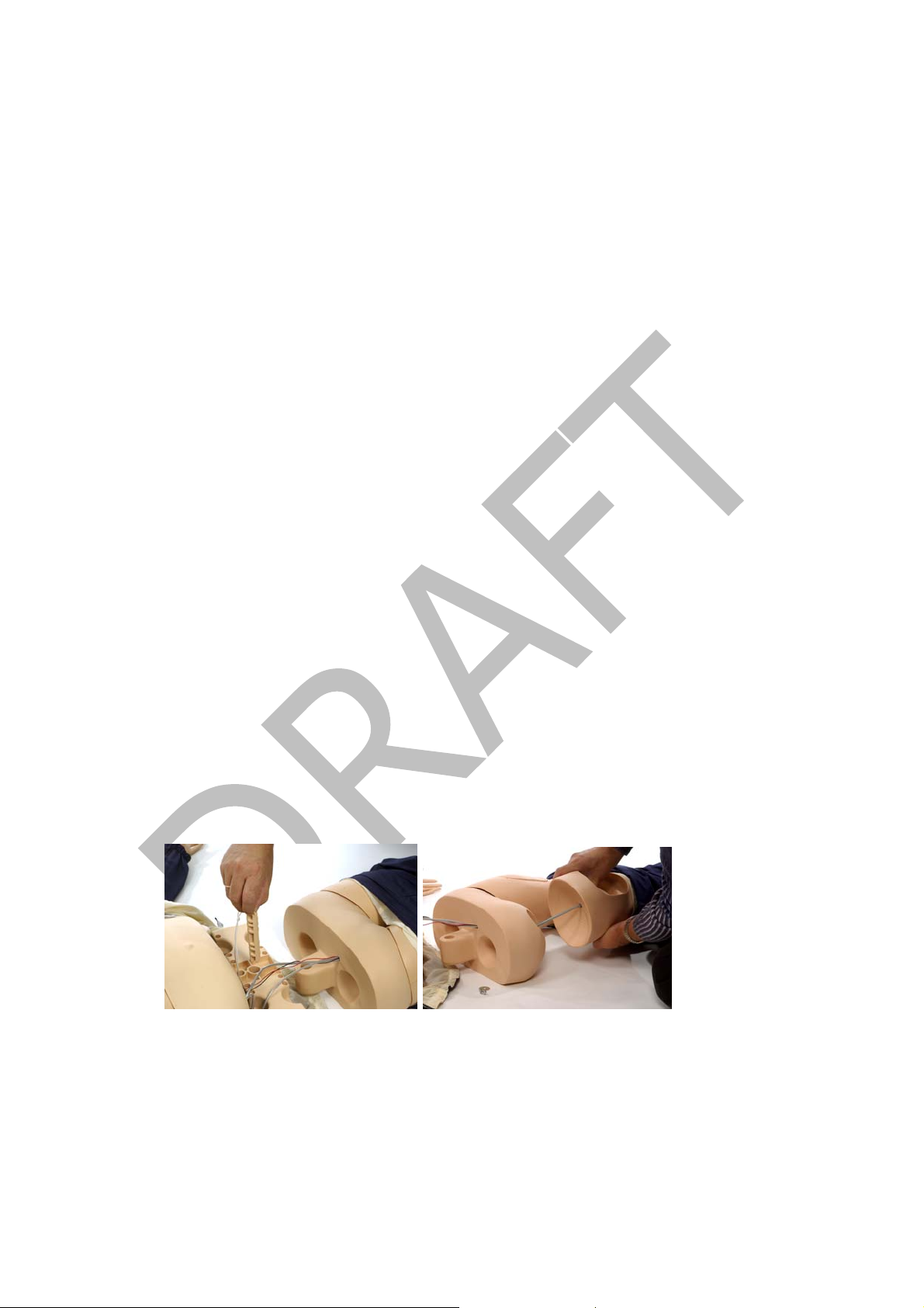
Attaching the Legs
Each leg is attached to the pelvis with a bolt, two washers, a spring and a wing nut.
To attach Legs:
1. Detach the torso’s lower chest skin and fold back as shown in picture below.
2. Remove the stomach pillow insert.
3. Remove the pelvis from the torso via bolt connection as shown in picture below.
Note: Be careful when detaching the pelvis from the torso for assembly of
the legs as there are connection wires from the pelvis to the torso.
4. Remove wing nut and washer from bolt inserted in the leg. (Leave spring assembly
in thigh of leg.)
5. Insert bolt through hole in pelvis
6. Slide washer and wing nut back over bolt.
7. Use a screwdriver to drive bolt into wing nut
8. Reattach the pelvis, with legs attached, to the torso via bolt connector
To remove legs, reverse procedure.
2004-10-08
5

Connect Blood Pressure Arm Cuff to torso
1. Place Blood Pressure cuff on the arm.
2. Connect the clear tubing on cuff to the blood pressure connector on simulator’s torso
(see photo). Insert the connector and twist slightly clockwise until it clicks into place.
Picture of simulator torso
with BP Connector
2004-10-08
6

Getting started with Resusci Anne Simulator
Airway Head
1. Head Tilt and Chin lift: Head tilt and chin lift can be performed on the head. If the
head tilt is performed, and airway obstruction is not activated, the airway valve will be
open allowing air passage to the lungs
2. Jaw Thrust: The jaw thrust maneuver can be performed on the head. If the jaw thrust
is performed, and airway obstruction is not activated, the airway valve will be open
allowing air passage to the lungs
3. Ventilation
The airway is designed to accept a broad range of airway management devices. Some
examples are:
• Oral and Nasal airways (OPA and NPA)
• Bag-Valve-Mask ventilation (BVM)
• Combitube
• Laryngeal Mask Airway (LMA)
• Laryngeal Tube Airway (LTA)
Lubricate the oral and nasal airways liberally with the lubricant provided prior to
inserting any instrument or tube into the airway. Additionally, instruments and tubes
should also be lubricated prior to use.
Note: There are electronic components mounted inside the simulator’s airway
management head. The following techniques should not be performed on this
simulator due to the inability to properly sanitize the airway if they are performed:
Mouth-to-mouth/Mouth-to-mask ventilation
Insertion of simulated vomit for suctioning
4. Speaker for voice transmission: When the simulator is “On” a speaker located
inside the airway head can produce pre-recorded voice transmission via remote
control. Live voice transmission can also be achieved by use of a microphone when
connected to the simulator’s torso.
Note: External microphone not supplied by Laerdal
5. Pupils: The simulator is delivered with a set of eyes containing normal pupils mounted
in the head. A separate case contains 3 sets of plastic eye inserts (normal, constricted
and dilated pupils) for use in simulating other conditions.
6. Cricoid Cartilage: A realistic cricoid cartilage is attached to the airway underneath the
face skin allowing the technique of cricoid pressure (Sellick M aneuver) to be
performed.
7. Carotid pulses: When the simulator is “On” palpable carotid pulses, synchronous to
the simulated ECG, are generated.
Note:
force as this will result in no pulse being felt.
8. Airway Obstruction: An airway obstruction can be activated from the remote control.
This feature simulates a complete blockage of the airways by shutting the airway
closure valve that controls air passage to the lung. The Resusci Anne Simulator is
Care should be taken when palpating the carotid pulse to not use excessive
2004-10-08
7

delivered with a default setting of “Manual” mode and means that the airway closing
valve is always in the open position. It may be manually closed with the use of the
remote control. Two other automatic settings can be selected via the remote control
to drive the airway obstruction feature. See later section titled “Set Airway Obstuction
(Open /Closed) Mode” found under Remote Conrol for more detail.
Note: When the Resusci Anne Simulator is “Off” the airway will remain open. If the
simulator is turned off while the closure valve is in the closed position it will open
automatically when the simulator is turned off.
9. Lung: The simulator is equipped with one disposable unilateral lun g that attaches to
the airway.
Torso
1. Spontaneous breathing: The simulator is equipped with a self-contained compressed
air container located inside the pelvis of the torso. A tube from the air container is
connected to a small bladder located under the lung. This bladder provides the
spontaneous chest rise and fall
• When the simulator is “On” the spontaneous breathing feature can be
manipulated by the remote control.
• Spontaneous breathing fill valve is built into the right side of the simulator.
The manual pump provided with the simulator can be used to fill the
compressed air container on an as-needed basis.
Note: See Maintenance section titled “Fillingthe spontaneous breathing air container” for
details on this feature
2. Chest compressions: The simulator demonstrates the correct anatomical landmarks
for external chest compressions. Chest compressions may be performed without the
risk of damage to the simulator’s spontaneous breathing bladder as long as
spontaneous breathing is not activated.
Note: To avoid damaging the spontaneous breathing bladder, do not perform chest
compressions while the spontaneous breathing function is activated.
3. Defibrillation: The simulator is equipped with two defibrillation connectors and four
lead connectors for use with AEDs or manual defibrillators. The ECG signal can also be
2004-10-08
8
monitored across these connectors. Using the remote control, the instructor can select
the “ignore defib” function to control whether or not the defibrillation shall result in
conversion to a perfusing rhythm. Paddle adapters are supplied for use with manual
defibrillators.
Need a
picture with
”4-Lead”
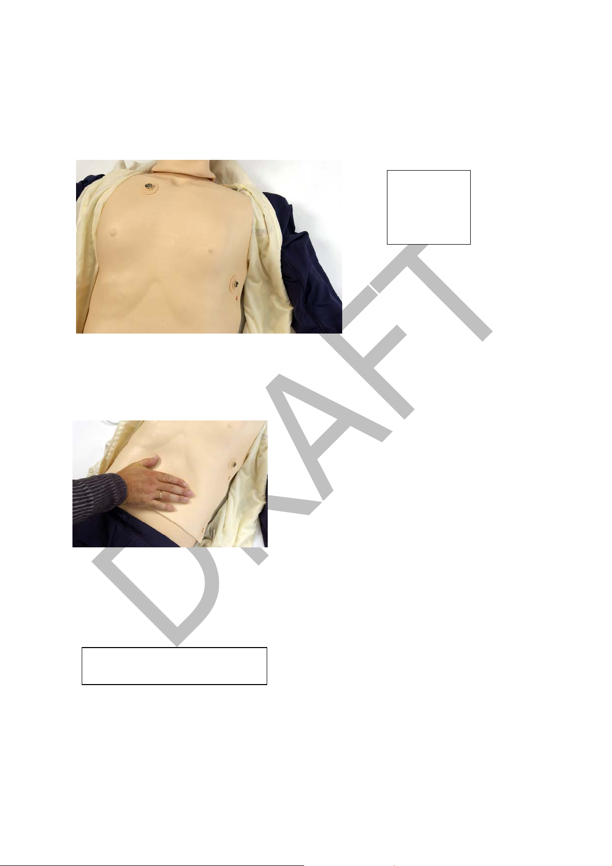
3. Stomach: The simulator is equipped with a stomach and pressure valve system that
allows stomach distension at inspiratory pressures of more than 25 cmH
O. To deflate
2
press gently on the stomach.
4. Heart and Lung Sounds: The simulator is equipped with hidden speakers for realistic
heart and lung auscultation.
5. Power Supply: The manikin is intended to operate from battery power. An AC power
adapter is included in the event the user prefers not to use battery power.
Picture showing connection to
power supply
2004-10-08
9
Remote Control
Communication between the remote control and the simulator is based on low power radio
frequency (RF) communication. If the remote control device is used in an environment
where RF communication is not desirable, or where interference from other sources makes
the remote control device inoperable, it is recommended to use the cable connection
between the remote control and the simulator. Using the direct cable connection disables
the RF circuits in both the remote control and the simulator. For use of this cable see later
section
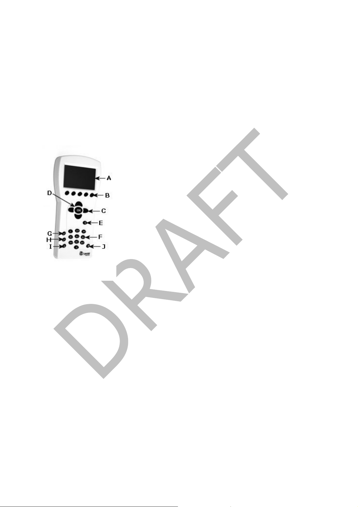
Overview of the Remote Control Device
A. LCD display: Displays status and operation information.
B. Quick execution buttons: Function keys. The function of each button is labeled
on the display above the button.
C. Navigation keys: Use keys to navigate and select functions on the display.
D. OK/Select key: Use this key to activate selected functions.
E. Cancel/Back key: Go back from sub menus without any changes.
F. Numerical keys: Use these keys to enter numerical data or to select numbered
parameters. Can also be used as alphanumerical keys to enter file and event-
names
G. Menu/Setup: Enter Setup Menu.
H. Scenario: Use this button to start a scenario.
I. Shift key
J. On/Off key: Press once to turn the unit on. Press again to turn the unit off.
2004-10-08
10
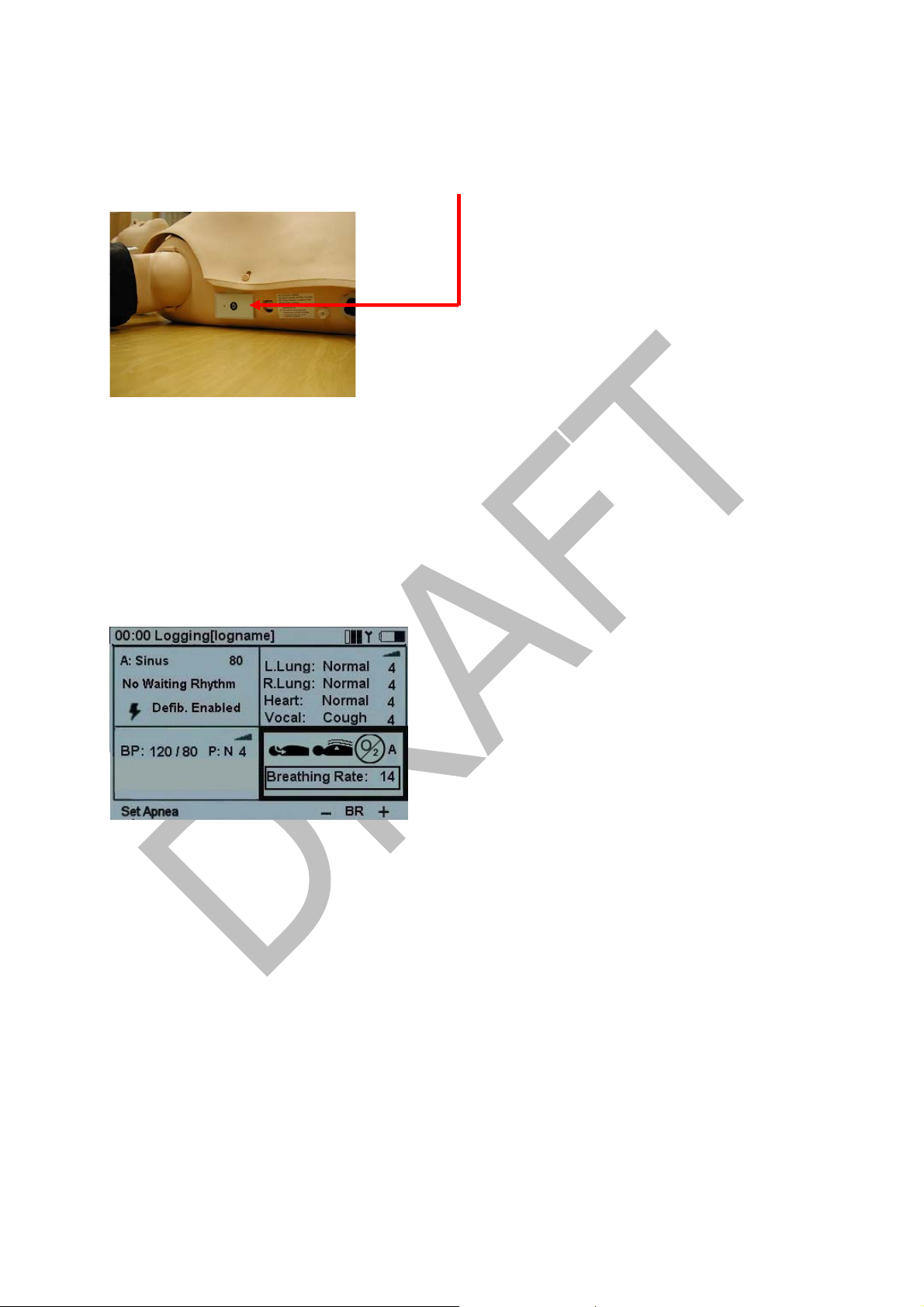
For Remote Control to properly recognize the Simulator
1. Turn on the simulator by pressing the “On/Off” button located on the right side of the
simulator’s torso.
2. Turn on the remote control by pressing the On/Off key (indicated by the letter J in
remote control picture above). The remote control will automatically detect the
simulator and set the initial parameters accordingly. A splash screen will be displayed
for a few moments until the main display is shown.
Note: If an error message appears stating “no reception”, make sure that the
simulator is turned on.
Main Display
The main display screen shows the current status and is a shortcut screen for modifying
some parameters using the quick execution buttons.
The main display is divided into five functional areas and a quick execution area:
1. The upper area is the Logging and Scenario status area. The log status and clock are
presented here together with the remote control battery status and a radio reception
indicator.
2. The ECG section is indicating Running Rhythm on the first line and Waiting Rh ythm on
the second line. ”Defib. Enabled” allows change to Waiting Rhy thm when a defibrillator
shock is given.
3. The sounds section controls the selected Heart, Lung and Vocal (spoken) sounds.
Volume for each sound can be controlled individually.
4. The Blood Pressure (BP) section shows the set BP, Pulse Strength and the Korotkoff
sound volume.
5. The Breathing rate section shows the set breathing rate, airway open/close status,
supplemental oxygen “active/not active” and airway closure status (M “manual”, A
“adjuncts”, or B “Bag-Valve-Mask” setting).
6. The quick execution bottom menus are shown at the bottom of each display window.
The functions of these buttons will change as the selected function area changes.
2004-10-08
11
 Loading...