

Page 1
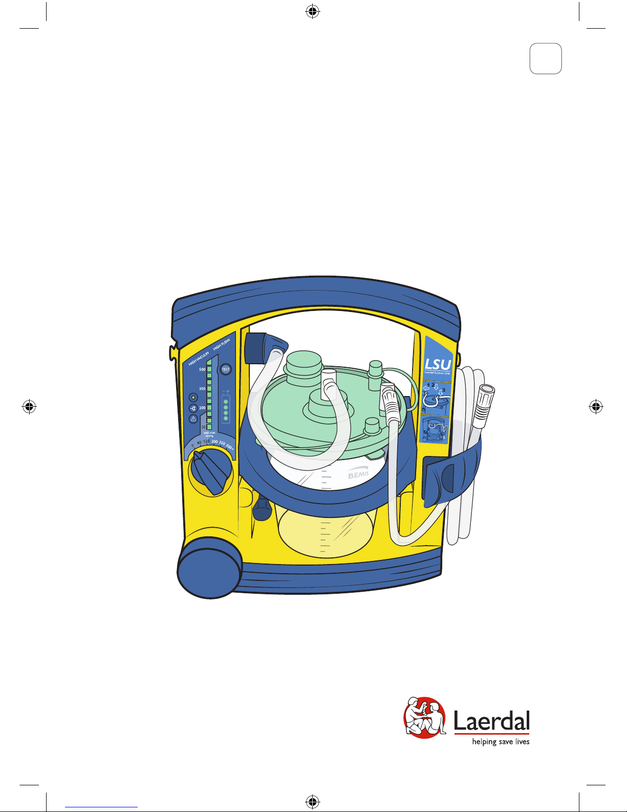
Laerdal Suction Unit
BEMIS Disposable Canister
User Guide
EN
www.laerdal.com
Cat. No. 78002001
Page 2
Read this User Guide carefully, and become thoroughly familiar with
the operation and maintenance of the Laerdal Suction Unit (LSU) before using it.
The LSU should only be used by persons trained in the use of medical
suction equipment.
The LSU is not suitable for use in the presence of flammable liquids or gases.
There can be a danger of explosion or fire.
The LSU is not intended to be used in MRI enviriments.
Do not re-use the canister or patient tubing. Re-use will lead to
increased risk of cross-contamination, degradation of performance and/or
device malfunction. Laerdal is not responsible for any consequences of re-use.
Do not use the LSU under environmental conditions that are outside the
ranges specified under section 9.6. This can endanger safety and adversely
affect operation of the device.
Even if the Operating Knob is in “0” position, voltage is present on some
of the internal circuitry, when the LSU is connected to mains. To fully
remove power, pull out the Power Cord.
Battery:
- The LSU must be charged between each clinical use
- To maintain satisfactory operation of the battery, it is recommended to place
the LSU on continuous charge when not in use.
- The LSU must be placed on charge for a minimum of 4 hours to reach full battery
capacity. The fast charging gives approx. 80% battery capacity after 3 hours (for a
new battery). Please note that repetitive 3 hour charging is not recommended.
- If it is not possible to place the LSU on continuous charge when not in use, make
sure the battery is charged for a minimum of 4 hours at least once a month. If LSU
battery is kept on constant charge, perform device test at least once a month to
exercise battery.
- Do not store the battery when it is discharged. Always fully charge the
battery before storage.
Do not block the Exhaust Outlet during use. This will lead to reduced flow and
can also cause damage to the LSU.
If overflow of liquid from the Canister into the pump is suspected, discontinue use of
the LSU and contact a Laerdal Service Center.
Disconnect the LSU from external power prior to cleaning. Use a minimum of
liquid to prevent any electrical shock hazard.
Do not immerse the LSU or allow it to stand in water or other liquids. This might
damage the device, and cause electrical hazard.
Do not pump any cleaning solution or other liquids through the vacuum pump,
i.e. through the Vacuum Connector. This can damage the LSU.
Use only accessories supplied by Laerdal or one of its authorized dealers to
help ensure that the LSU operates satisfactorily.
Caution: Federal (US) law restricts this device to sale by or on the
order of a physician.
2
1 Cautions and Warnings
Page 3

3
1 Cautions and Warnings ............................................................. 2
2 Introduction ................................................................................... 4
2.1 Indications for Use................................................................. 4
2.2 Contraindications ................................................................. 4
2.3 Features and Benefits............................................................. 4
2.4 Limited Warranty .................................................................. 5
2.5 Unpacking ................................................................................ 5
3 Description ...................................................................................... 6
3.1 Quick Reference Guide ......................................................... 6
3.2 User Interface ........................................................................... 7
3.3 Canister ................................................................................... 12
3.4 Power Sources / Connector Sockets ............................... 13
3.5 Automatic Power-save Function ....................................... 13
4 Operation ....................................................................................... 14
4.1 Getting Started ...................................................................... 14
4.2 Replace the Canister ............................................................ 15
4.3 After Use ................................................................................. 16
5 Maintenance .................................................................................. 16
5.1 General .................................................................................... 16
5.2 Battery ..................................................................................... 16
5.3 Clean the Cabinet ................................................................. 16
5.4 Charge the Battery ............................................................... 17
5.5 Check the Battery Quality .................................................. 17
5.6 Replace the Battery .............................................................. 18
6 Servicing ......................................................................................... 18
7 Troubleshooting ....................................................................... 19
8 Parts List ........................................................................................ 20
9 Specifications ................................................................................ 21
Page 4

2.1 Indications for Use
The LSU is a portable, electrically powered, medical suction equipment
intended for field and transport use. It is intended for intermittent
operation to remove secretions, blood or vomit from a patient´s airway
to allow ventilation. Higher vacuum levels are generally selected for
oropharyngeal suctioning, and lower vacuum levels are usually selected
for tracheal suctioning and the suctioning of children and infants.
2.2 Contraindications
None known.
2.3 Features and Benefits
- Splash proof, rugged and solid.
- Easy access to the tubing.
- Equipped with an internal battery that can easily be replaced
without using tools.
- Charging of battery can be done directly from AC or DC mains -
no external charger is needed.
- Fast charge of 3 hours, giving approx. 80% battery capacity.
- Operation possible from internal battery and directly from AC or DC mains
- no adapter is needed.
- A large combined ON/OFF switch and vacuum selector makes operation
easy even with heavy-duty gloves.
- A green LED bar graph makes it easy to observe the actual vacuum level
during operation.
- Another green LED bar graph indicates approx. remaining battery capacity.
4
2 Introduction
Page 5

5
2.4 Limited Warranty
The LSU comes with five (5) year limited warranty*. See the enclosed
“Laerdal Global Warranty” for terms and conditions.
The warranty is also available at www.laerdal.com
* Excluding the canister, tubing systems and battery.
2.5 Unpacking
- Remove the LSU from its packaging and inspect all parts for
damage. If there are any signs of damage or if any parts are missing, imme-
diately notify Laerdal or one of its authorized dealers.
- Insert the battery according to section 5.6.
- Place the LSU on charge for a minimum of 4 hours to make sure you have
a fully charged battery (see section 5.4).
- Perform the Device Test according to section 3.2.3.
Page 6
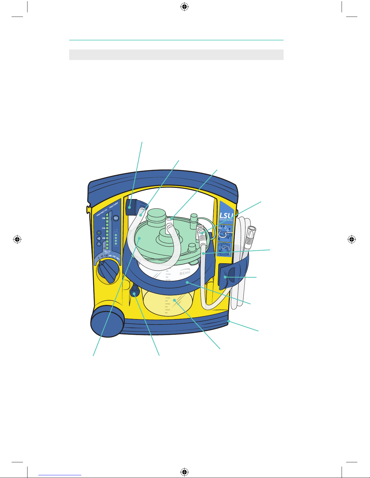
3.1 Quick Reference Guide
LSU w/Disposable Canister
6
3 Description
LSU Vacuum
Connector
Patient Suction
Tubing
Canister Holder
Battery
Door
Canister Holder
Release Arm
Canister
Canister Lid w/Bacterial
Filter & Shut-Off Valve
Strap for Patient
Suction Tubing
Vacuum Connector
Tubing
Vacuum
Port
Patient
Port
Page 7

3.2 User Interface
3.2.1 Operating Knob
The Operating Knob is a combined ON/OFF switch and vacuum selector,
located at the bottom of the User Interface.
The LSU is switched ON by turning the Operating
Knob to the required setting. Each setting
indicates the maximum achievable vacuum level
for the selected position (80, 120, 200, 350,
500+ mmHg). The free air flow value changes
along with the increasing vacuum settings
(see section 9.4 for details). The LSU is switched
OFF by resetting the Operating Knob to “0”.
7
TEST-Button
Power ON Indicator
Vacuum Indicator
Battery Status
Indicator
Operating Knob
External Power Indicator
Failure Mode Indicator
Page 8
3.2.2 Indicators
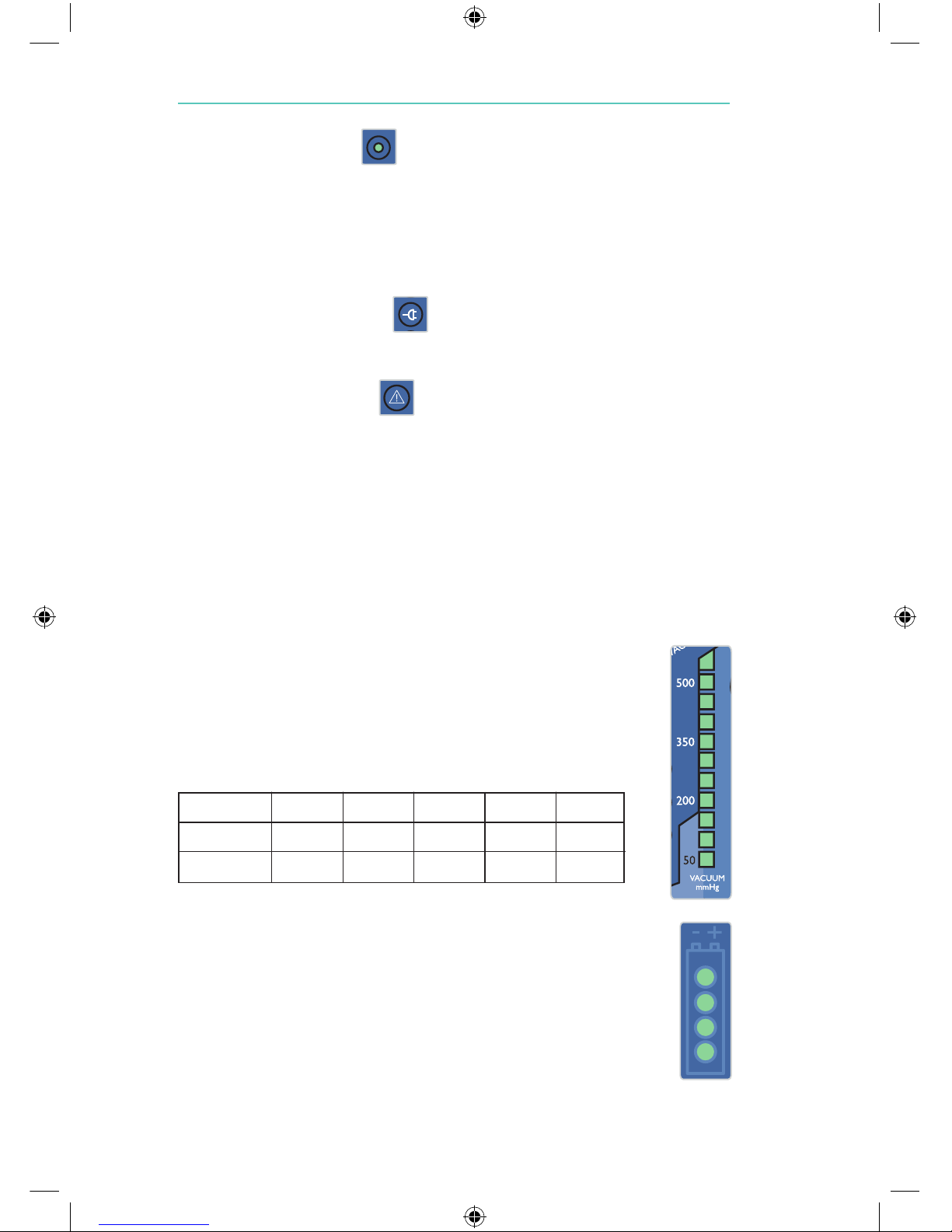
3.2.2.1 Power ON Indicator
This green LED has 3 modes:
- It is lit continuously while the LSU is switched ON.
- It flashes rapidly (approx. twice per second) during the Device Test.
- It flashes slowly (approx. once per second) while the Automatic
Power-save Function is activated, if the Device Test is interrupted
and when the battery is discharged.
3.2.2.2 External Power Indicator
This green LED is continuously lit while external AC- or DC-power is
connected.
3.2.2.3 Failure Mode Indicator
The red LED is lit when a possible malfunction of the LSU has been
detected. If lit turn the LSU OFF, and then ON again to check if the
indication disappears*. Provided that the indication does not occur
again the LSU can be operated. If the Indicator continues to be lit after
three OFF/ON cycles and after replacing the battery with a fully charged
battery, discontinue use and contact a Laerdal Service Center. (See section 6).
*Failure Mode Indication caused by external electrical interference may occur on any digital
equipment including the LSU. Such fault will usually not be repeated.
3.2.2.4 Vacuum Indicator
This green LED bar graph displays the actual
vacuum level during operation of the LSU. Each fully lit
segment represents 50 mmHg. If a segment has a weak
light, this represents 25 mmHg (e.g. 125 mmHg means
2 fully lit and 1 weakly lit segments).
3.2.2.5 Battery Status Indicator
During operation from internal battery and during charging
the displayed values must only be used as indications.
Several parameters can influence battery capacity e.g. device settings,
state of battery, temperature etc.
8
mmHg 80 120 200 350 500
kPa 11 16 27 47 67
mBar 107 160 267 467 667
Page 9

9
This green LED bar graph has 3 functions:
During operation from internal battery - indicates approx. remaining battery capacity.
Note: Immediately after turning the LSU ON and immediately after switching from external
power to internal battery operation, all 4 LED’s will flash for 5 seconds before the remaining
battery capacity is displayed. Due to the nature of voltage based battery capacity measurement,
the battery status indication may differ from unit to unit. Each battery may vary in voltage versus
remaining capacity, thus allowing for variability in the reading. Other outside variables such as
temperature may also affect accuracy. The indication is targeted to show battery capacity as
indicated below. The graph shows how the accuracy of the indication can vary.
TYPICAL REMAINING BATTERY CAPACITY
(for a new battery stored in room temperature ) OUTPUT
> 50% 4 LEDs lit.
30 - 50% 3 LEDs lit.
20 - 30% 2 LEDs lit.
< 20% 1 LED lit.
Battery Low; (min. 1 minute of operation left based on
500+ mmHg/free flow). 1 LED flashes.
Note: If the LSU or the NiMH battery has been stored at low temperatures
(< 12 °C / < 54 °F), the LSU may indicate lower remaining battery capacity than actual when
first switched on. This is due to the nature of NiMH batteries. The battery indicator may
flash on one LED, which normally indicates Battery Low. The LED may continue to flash
until the LSU temperature is above 12 °C / 54 °F and the LSU is switched off and on again.
The low battery indication in this instance is not a correct indication of the residual
battery capacity.
During charging - indicates approx. achieved battery capacity.
CAPACITY OUTPUT*
< 75% The LED’s will be lit sequentially.
75-80% 3 LED’s lit and 4th flashing.
> 80% 4 LED’s lit.
*Note: If no battery is installed, the battery status indicator will be fully lit for approx. 5 sec.
until it is automatically turned off.
During the Device Test - indicates which step of the test is currently in
progress or which corresponding test result is being displayed:
LED 1 (lower LED) lit = STEP 1, LED 2 lit = STEP 2 etc.
Page 10
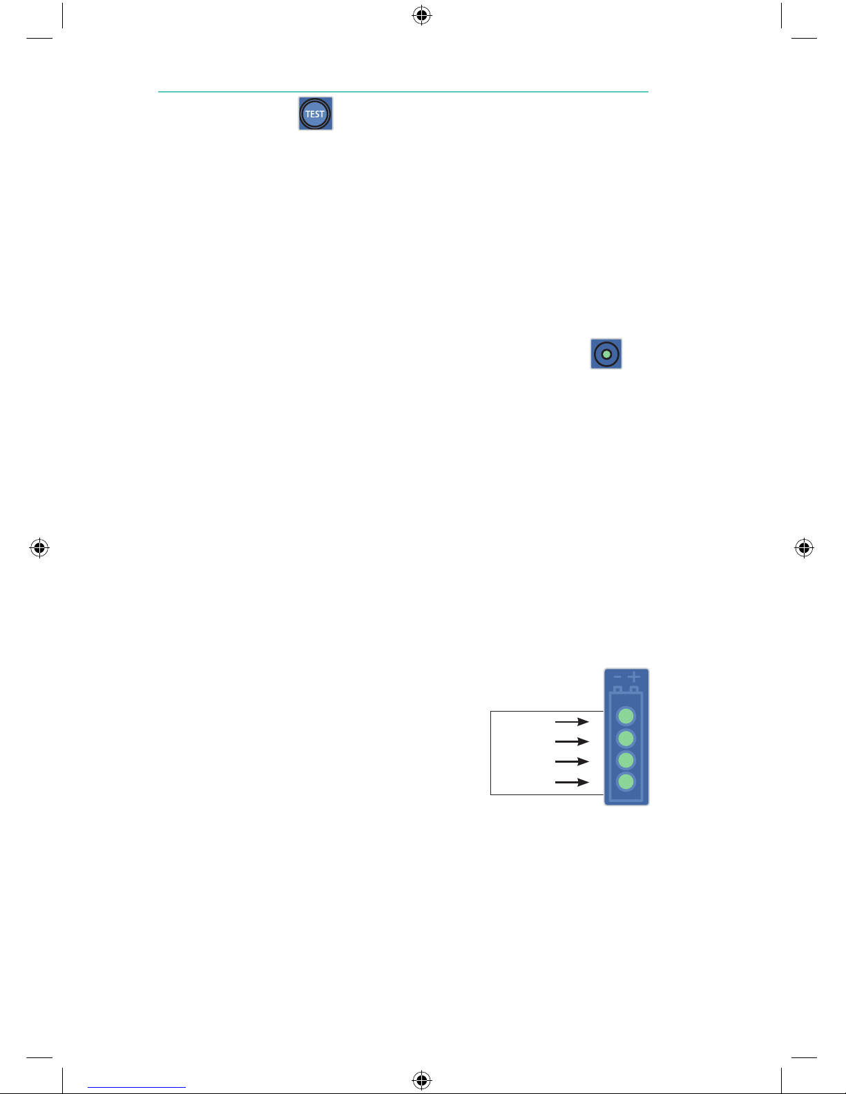
3.2.3 TEST-Button
This button allows you to run a 4-step user initiated Device Test
program to identify whether the LSU operates satisfactorily, is assembled
correctly, or if it needs service:
- STEP 1 - Checking for occlusions in the Suction System (including
canister and tubing).
- STEP 2 - Checking the vacuum build-up efficacy of the Pump System.
- STEP 3 - Checking the max. achievable vacuum level of the LSU. (reaches
this level within 10 seconds).
- STEP 4 - Checking for air leakage in the Pump System (including canister
and tubing).
To indicate that the LSU is in test mode, the Power ON Indicator
will flash rapidly (approx. twice per second) until you exit the test
program.
BEFORE YOU START THE DEVICE TEST
- Before you press the TEST-Button, make sure the Patient Suction Tubing
is not occluded or bent.
DEVICE TEST DESCRIPTION
- Press and hold the TEST-Button while setting the Operating Knob to
500+ mmHg.
Note: Do not release the TEST-Button until min. 2 seconds after the
Operating Knob has been set to 500+ mmHg. The test will start immediately.
- As soon as LED 2 of the Battery Status
Indicator comes on (takes approx. one
second) fully occlude the Patient
Suction Tubing.*
- Keep the tubing occluded until LED 1
comes on. To read the test results
see next page.
Note: If you need to interrupt the test and revert to normal operation, turn the
Operating Knob to another position and then select the required setting.
* If the tubing is not occluded within 2 minutes, the test will be interrupted and
the Power ON Indicator will start to flash slowly (approx. once per second).
To restart the test, set the Operating Knob to “0” and then start over again.
10
LED 4
LED 3
LED 2
LED 1
Page 11
11
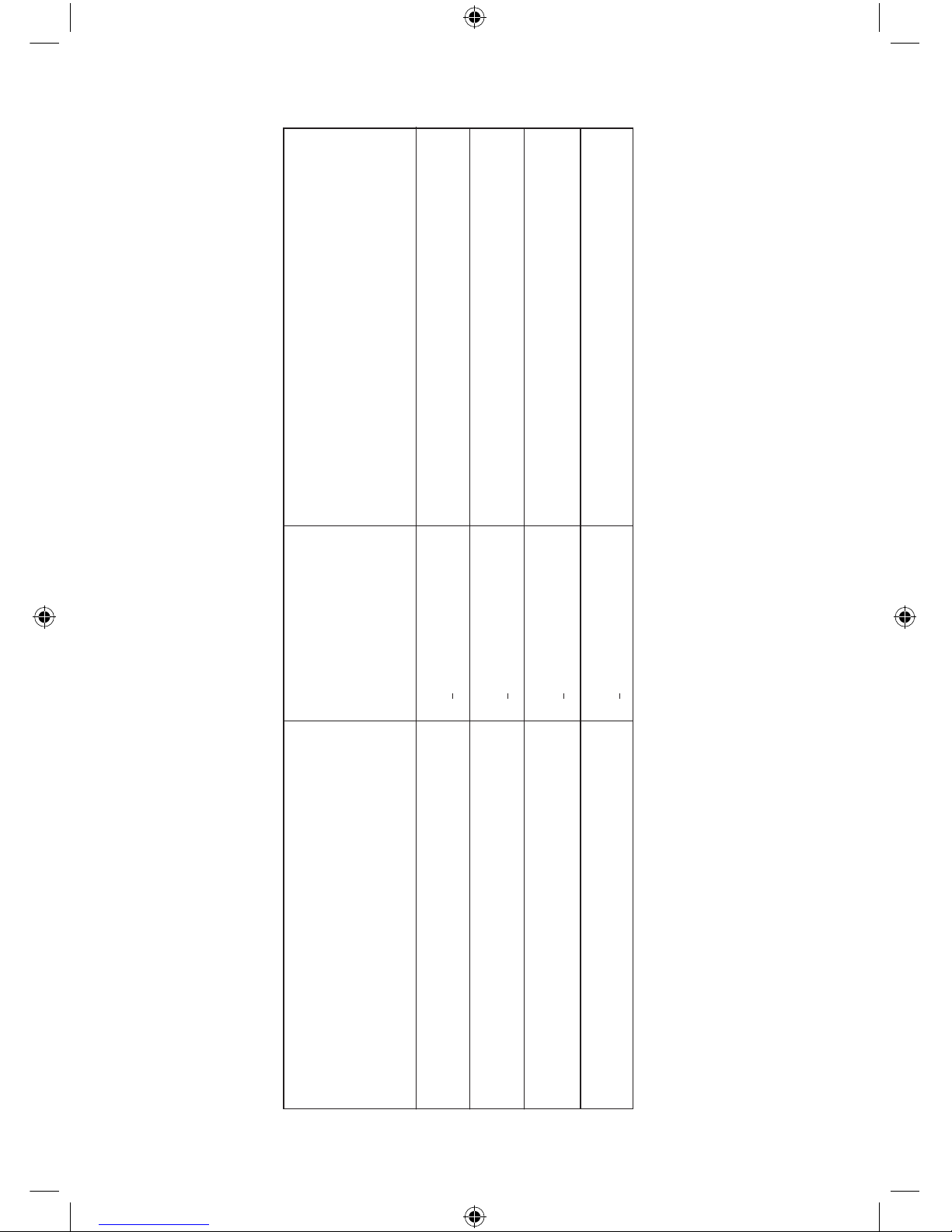
TO DISPLAY THE TEST RESULTS:
After the test is completed, the Vacuum Indicator will automatically display the result from STEP 1. To display the results from STEP 2, 3 and 4,
simply press the TEST-Button once for each STEP. If you continue pressing the button after the STEP 4 result has been displayed, the
earlier results will be repeated (STEP 1,2,3,4,1,etc.). To exit the test program, set the Operating Knob to another position.
Note: If the LSU does not pass one or more of the steps in this test after suggested actions are taken, contact Laerdal Service Center (see section 6).
TEST STEP
DISPLAYED ON THE
BATTERY STATUS INDICATOR
STEP 1 - Occlusions
STEP 2 - Vacuum Build-Up Efficacy -
within 3 seconds
STEP 3 - Max. Achievable Vacuum -
within 10 seconds
STEP 4 - Air Leakage
TEST RESULT
DISPLAYED ON THE
VACUUM INDICATOR
Test Passed:
100 mmHg. Test Passed:
300 mmHg.
Test Passed:
500 mmHg.
Test Passed:
450 mmHg.
ACTION
IF TEST FAILED
Check possible occlusions (e.g. twisted tubing) and run the Device Test again.
Check Connectors, Tubes and Canister Lid for leakage or damage. Check
exhaust outlet for occlusion and run the Device Test again
Check Connectors, Tubes and Canister Lid for leakage or damage. Check
exhaust outlet for occlusion and run the Device Test again
Check Connectors, Tubes and Canister Lid for
leakage or damage and run the Device Test again
<
>
>
>
Page 12
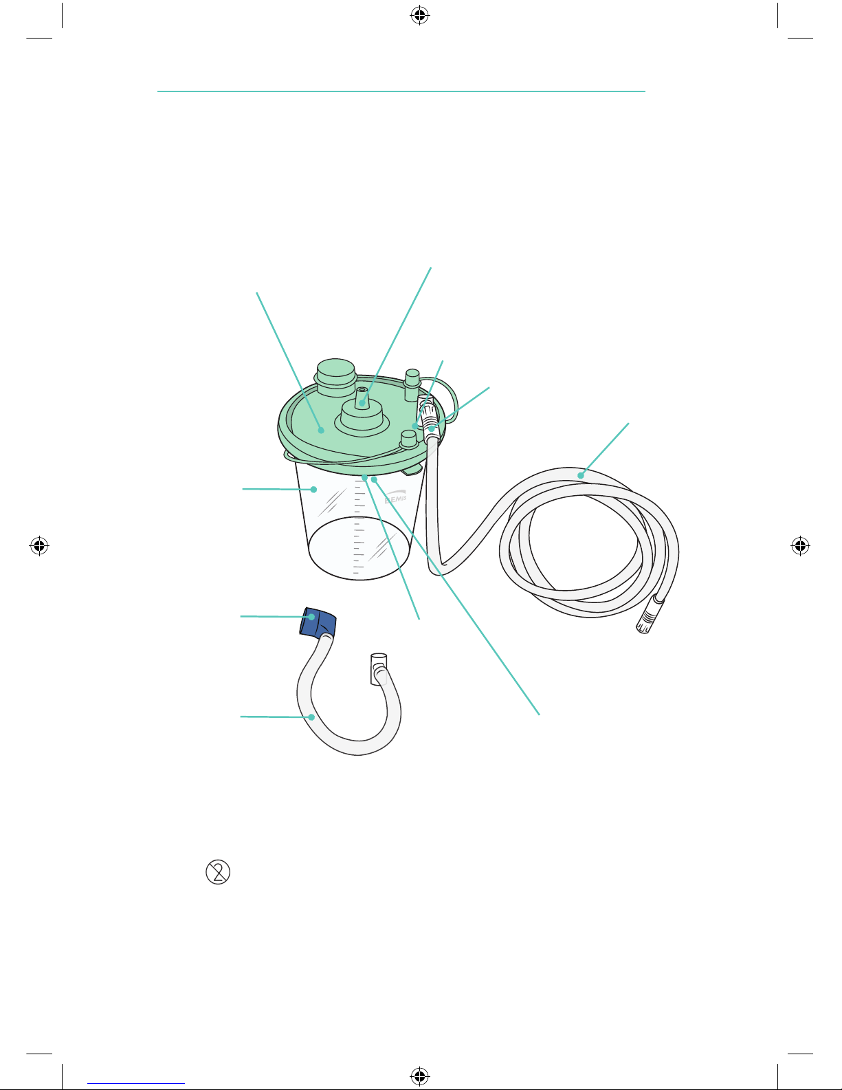
3.3 BEMIS™ HI-FLOW Suction Canister
The disposable Canister consists of:
- A 1200 ml transparent plastic Canister.
- Bacterial Filter - 99.99% DOP rated.
- Shut-Off Valve and Foam Guard seals tightly to prevent fluid overflow.
The Canister Lid contains a Shut-Off Valve that shuts off the vacuum
if the Canister is full or the LSU tips over. To reset the valve,
remove the Vacuum Connector Tubing from the LSU.
Note: All parts are Single Use and must be replaced after each use.
12
Vacuum
Connector
Tubing
LSU Vacuum
Blue Angled Connector
Disposable
Canister
Vacuum Port
Patient Port
Angled Connector
(Patient Port)
Bacterial Filter
Patient Suction
Tubing
Canister Lid
Shut-Off Valve and
Foam Guard
Page 13
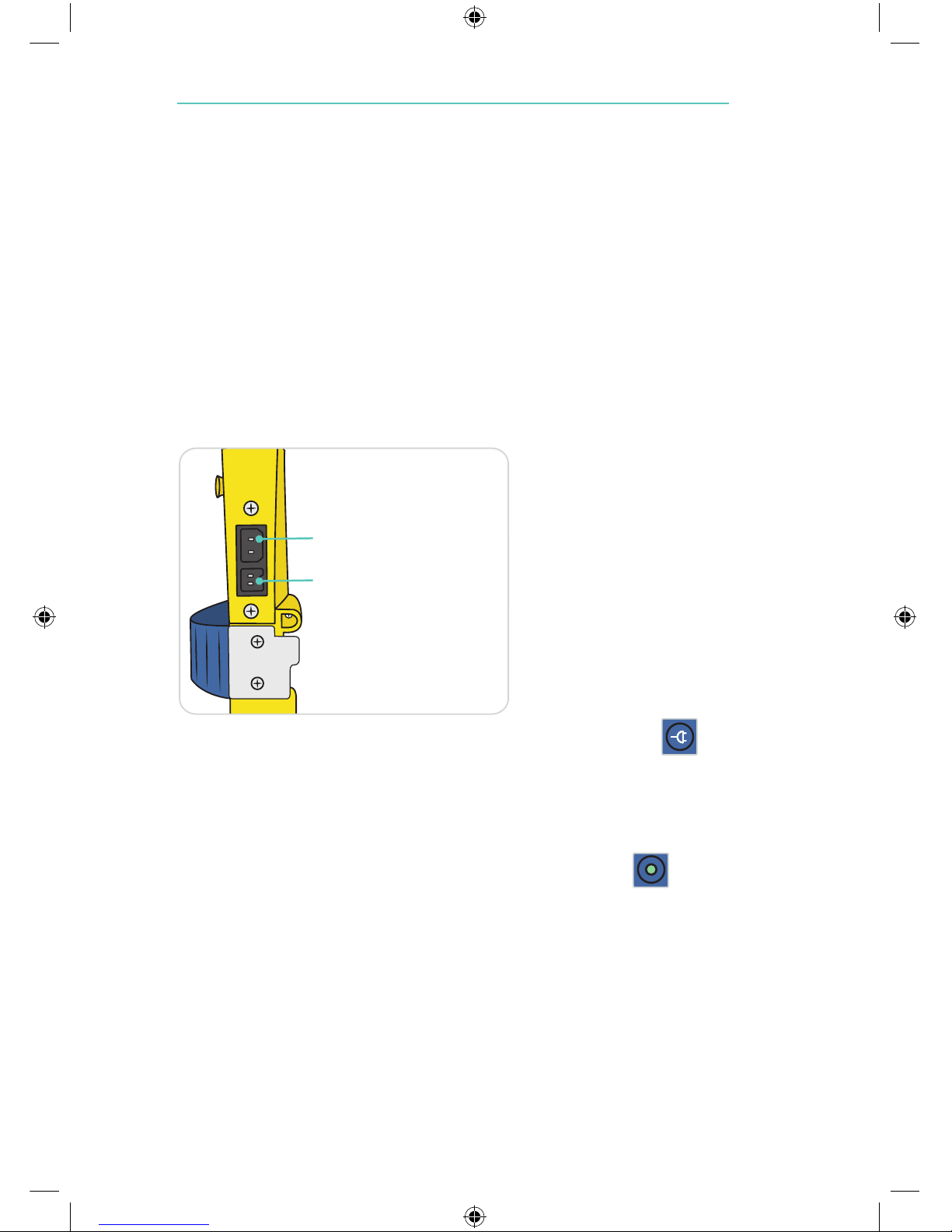
3.4 Power Sources / Connector Sockets
The LSU is delivered with an AC Power Cord for connection to AC
mains and a DC Power Cord for connection to DC mains.
The device can be operated from the internal battery, and can be
operated or charged from the following external Power Sources:
- AC mains when used with the AC Power Cord: (Max. length 1.5 m.)
100-240 VAC (50/60 Hz).
- DC mains when used with the DC Power Cord: (Max. length 1.5 m.)
12-28 VDC.
A Wall Bracket to hold the LSU during operation and charging is
available separately (see section 8).
External power connection will cause the External Power Indicator
to be lit.
3.5 Automatic Power-save Function
The LSU has an Automatic Power-save Function that switches OFF
the pump motor. While in this mode, the Power ON Indicator will
flash slowly (approx. once per second).
This function will be activated when the Operating Knob is set to 200,
350 or 500+ mmHg and the actual vacuum level has been
continuously higher than 120 mmHg for 2 minutes.
To exit the Power-save Mode and revert to normal operation, set the
Operating Knob to any position and then go back to required setting.
13
AC Connector Socket
DC Connector Socket
Page 14
4.1 Getting Started
Note: Read all the Cautions and Warnings listed in section 1 thoroughly before
you use the LSU.
1. Check that no parts are missing and that all parts are clean.
2. If you decide to operate the LSU from external power, connect
either external AC- or DC-power to the LSU as described in
section 3.4. If you decide to operate the LSU from internal battery, check
that battery is installed.
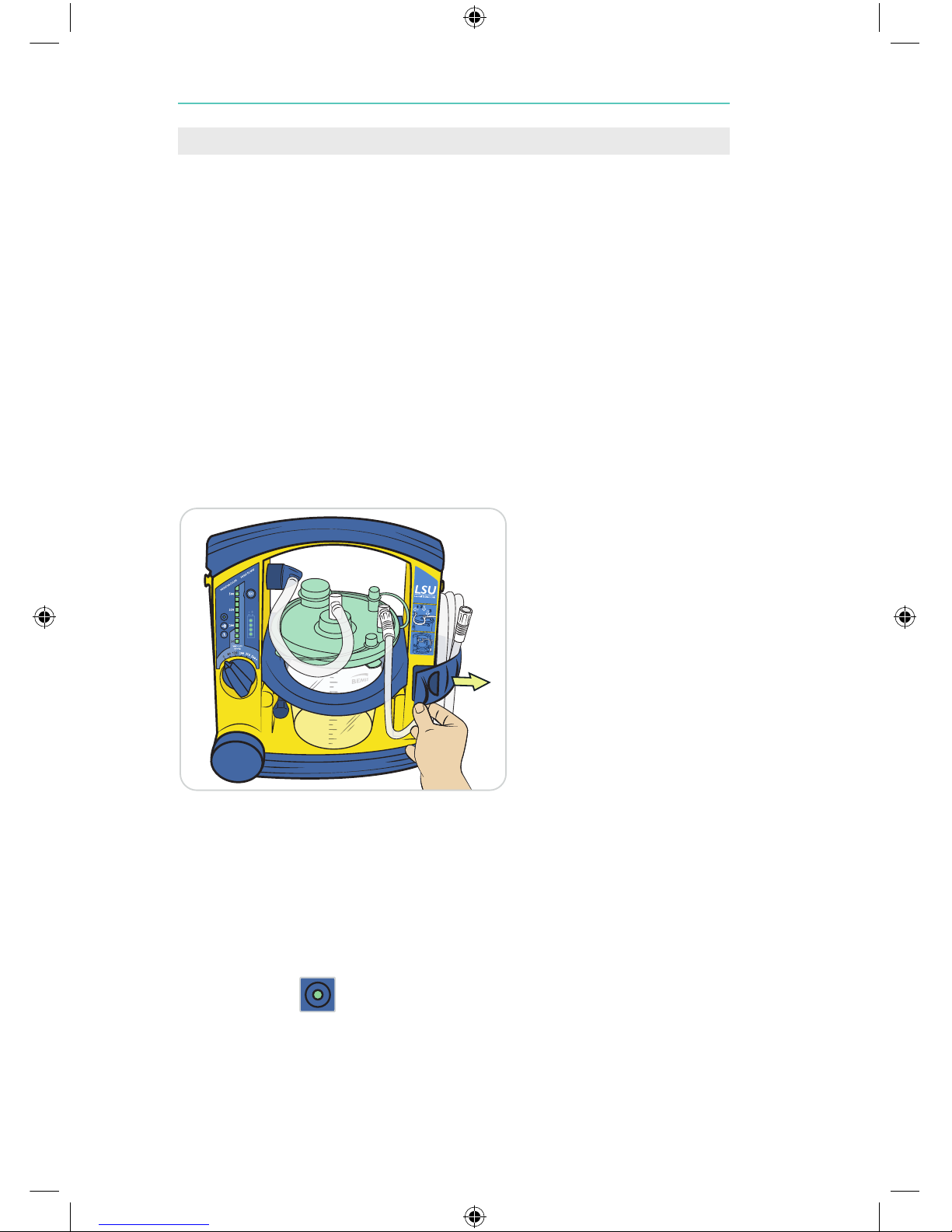
3. Ensure the Patient Suction Tubing is securely connected to the Patient
Port on the Canister Lid.
4. Check that a suction catheter is attached to the patient suction tube or
suction adapter. Do not use the suction tube or suction adapter without
a suction catheter attached. Proceed as follows:
5. Release the Patient Suction Tubing by releasing the Strap.
6 The LSU should be operated in the upright position to prevent overflow
of suctioned material.
7. Set the Operating Knob to the required vacuum level, and the LSU will
automatically be switched ON and start to operate. The green Power
ON Indicator is continuously lit while the LSU is switched ON.
14
4. Operation
Page 15
15
4.2 Replace the Canister
Note: It is recommended to replace the Canister when it is 3/4 full.
When liquid reaches the top of the Canister, the LSU will not suction
any more liquid. If overflow of liquid from the Canister into the pump
is suspected, contact a Laerdal Service Center for advice (see section 6).
Overflow of suctioned material can damage the device.
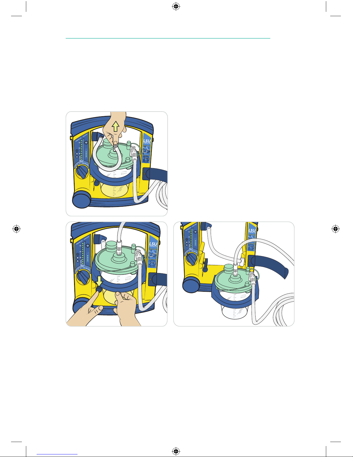
To remove the Canister, proceed as follows:
1. Disconnect the Angled Connector
from the Vacuum Port on the Lid.
Connect the “suction end” of the
Patient Suction Tubing to the
Vacuum Port to avoid spillage.
2. To release the Canister Holder, press down the Canister Holder Release Arm
while sliding the Holder towards you. Remove the Canister from the Holder.
3. Safely dispose of the contents of the Canister according to local protocols.
4. Replace parts according to section 3.3.
5. Install the Canister in the Holder, slide the Holder into position and connect tubing to the Canister. Ensure the lid is properly sealed.
Setup
Page 16

4.3 After Use
- When suction is complete, set the Vacuum Switch to “0” and inspect all
parts for damage or excessive wear. Replace parts if necessary.
- Clean the LSU according to section 5.3.
- Perform the Device Test according to section 3.2.3.
- Place the LSU on charge (see section 5.4).
5.1 General
- Make sure the maintenance instructions under section 4.3 are followed.
- If the device is not in frequent use (i.e. less than once a month), the Device
Test should be performed both on a monthly basis and after each use.
5.2 Battery
- To maintain satisfactory operation of the battery, it is recommended to
place the LSU on continuous charge when not in use.
- Replace the battery when it does not pass the Battery Quality Check
(see section 5.5 for details), or after 3 years.
- Do not store the LSU with an discharged battery.
5.3 Clean the Cabinet
Warning: Disconnect the LSU from external power prior to cleaning.
Use a minimum of liquid to prevent any electrical shock hazard.
Do not immerse the LSU or allow it to stand in water or other liquids.
This can damage the device, and cause electrical shock resulting in injury
to persons.
- Use a cloth or sponge that is dampened with a mild detergent (hand dishwashing liquid or similar) to clean the external surfaces of the LSU. Use
a detergent that is compatible with the materials listed under section 9.7,
and follow the detergent manufacturer´s instructions.
- Use a cloth or sponge dampened with water and wipe the surfaces again.
- Dry the surfaces using a clean cloth or a paper towel.
16
5. Maintenance
Page 17
17
5.4 Charge the Battery
The internal rechargeable battery can be charged directly from external
AC- or DC-power as described in section 3.4. No external charger is needed.
To charge the battery, proceed as follows:
1. Make sure the Operating Knob is set to “0”. Connect either
external AC- or DC-power to the LSU and charging will
start automatically.
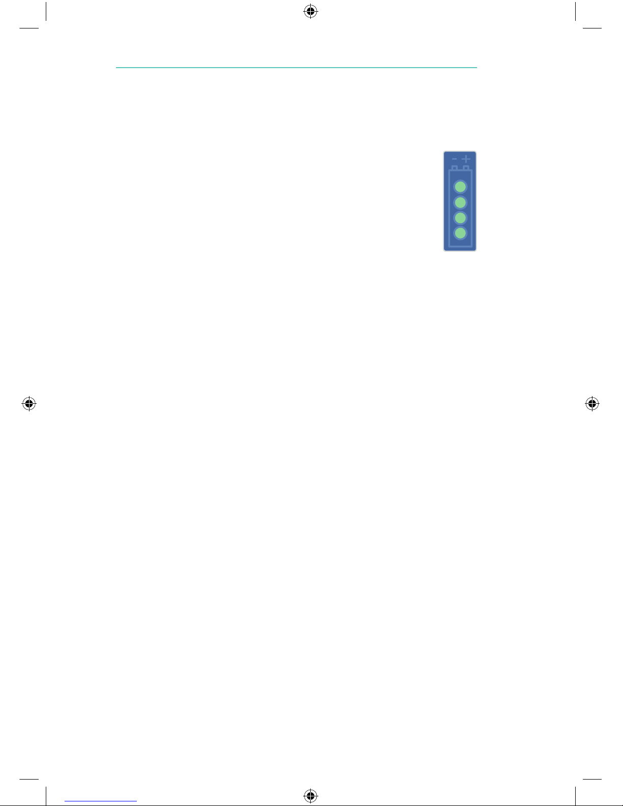
2. During charging the Battery Status Indicator will indicate
approx. achieved battery capacity (see section 3.2.2.5
for details).
3. The LSU must be placed on charge for a minimum of
4 hours to reach full battery capacity. The fast charging
gives approx. 80% capacity after 3 hours (for a new battery).
Repetitive charging for only 3 hours is not recommended.
Note:
- To maintain satisfactory operation of the battery, it is recommended to place
the LSU on continuous charge immediately after use.
- It is recommended to always fully charge the battery. Repetitive charging to
a lower capacity level will reduce battery life.
- If it is not possible to place the LSU on continuous charge when not in use,
make sure the battery is charged for a minimum of 4 hours at least once
a month.
- Do not store the battery when it is discharged. Always fully charge the battery
before storage.
- The recommended ambient temperature for charging is from 15 °C to 25 °C
(59 °F to 77 °F ).
- The battery will not be charged when the LSU is in operation.
- If no battery is installed, the battery status indicator will be fully lit for approx.
5 sec. until it is automatically turned off.
5.5 Check the Battery Quality
If poor battery quality is suspected, charge the battery for a minimum
of 4 hours and then perform the following test without connection to
external power:
- Run the Device Test and then let the LSU operate continuously at
500+ mmHg/free flow for 20 minutes.
- If the LSU stops before completing the 20 minutes, the battery should be
discarded.
Page 18
5.6 Replace the Battery
Note: Use only batteries recommended by Laerdal or one of its authorized dealers.
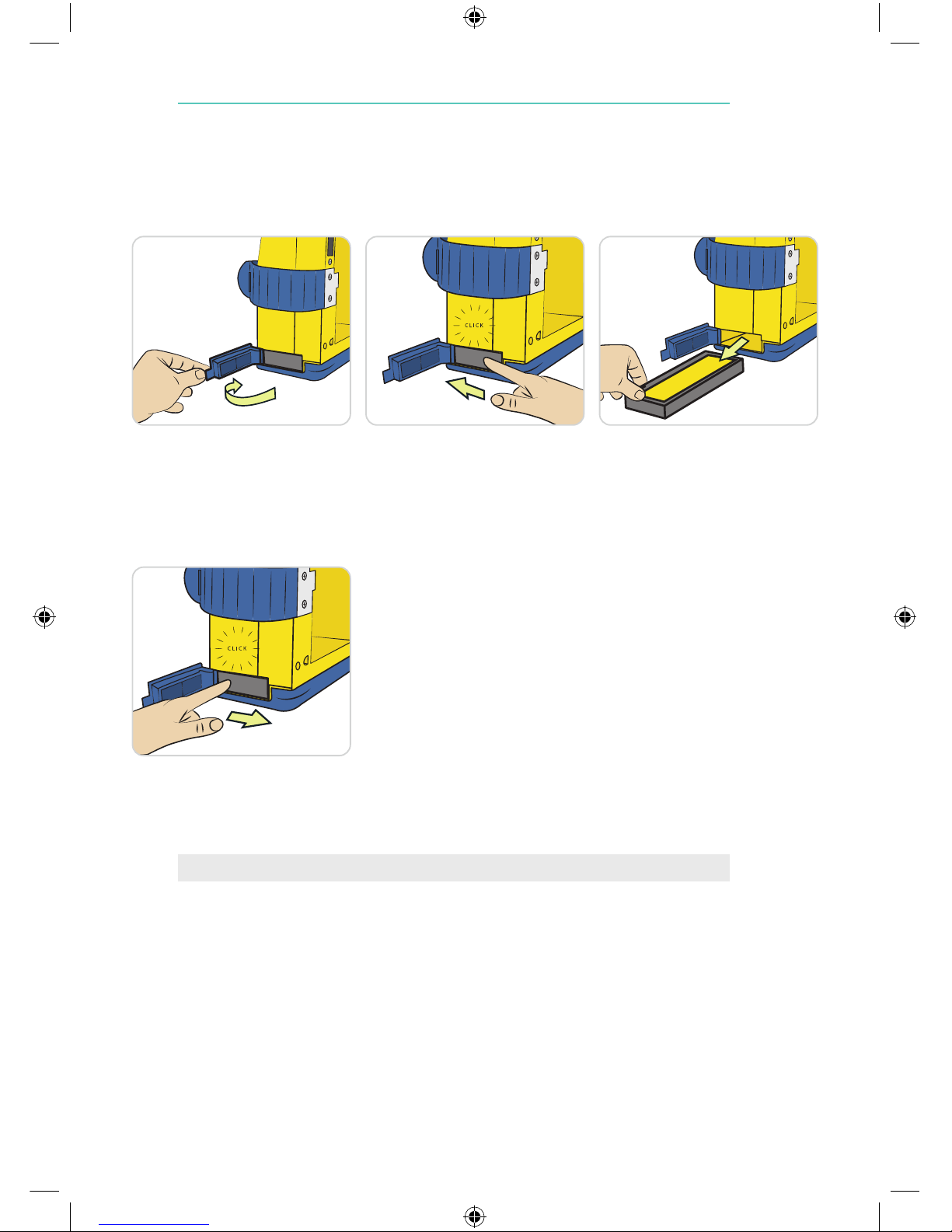
4. To insert a battery, push it fully in and then to
the right to lock it.
5. Close the Battery Door.
6. After inserting the battery, place the LSU on
charge unless a fully charged battery is inserted.
There are no user serviceable parts inside the cabinet. Do not open
the cabinet. Refer servicing to a Laerdal Service Center or Laerdal
authorized LSU servicer. Contaminated suction units will not be
serviced by Laerdal Medical.
*If you are discarding the battery, dispose of safely according to local protocols.
18
6. Servicing
1. Open the Battery Door.
2. To remove the battery,
push and move it slightly to
the left and then release.
3. Withdraw the battery
from the LSU.*
Items Included
Items Included
Items Included
Items Included
Page 19
19
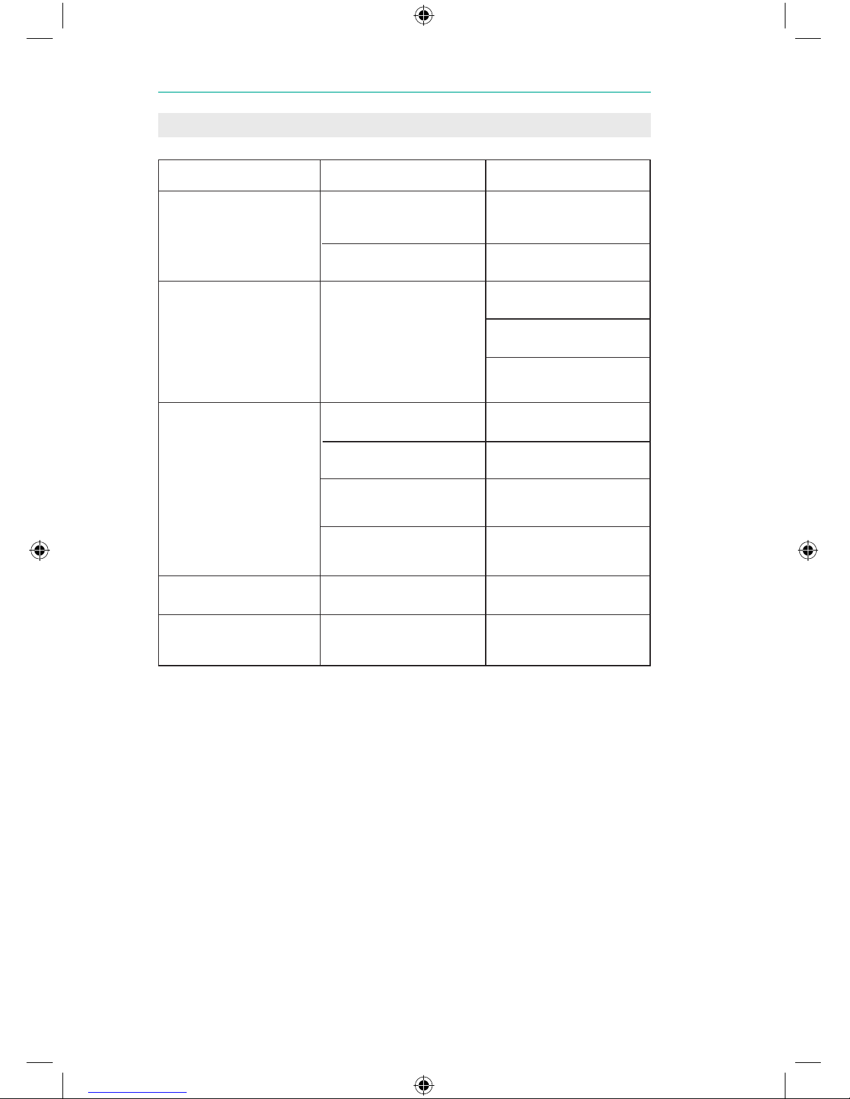
7. Troubleshooting
FAULT
The LSU does not operate
with the AC or DC Power
Cord connected.
The LSU cannot be operated
from the internal battery.
The LSU operates, but little
or no suction available.
Battery Status Indicator is
not ON.
Vacuum Indicator indicates
more than 100 mmHg with
free air flow
CONDITION
External Power Indicator is
not lit when the Operating
Knob is set to “0”.
External Power Indicator is lit.
Power ON Indicator is OFF.
Floater valve is closed.
Canister full.
Poor vacuum connection
between Pump Unit and
Canister.
Patient Suction Tubing twisted
or blocked.
Battery is not charged.
Tube(s) is kinked or twisted
ACTION
Check power cord connections and the external AC- or
DC-power source.
The LSU must be returned
for service (see section 6).
Check that battery is installed.
Place the LSU on charge.
If still faulty after charging completed, remove and replace the
battery (see section 5.6).
Unplug the Filter/Vacuum
Tubing to release the vacuum
Remove and replace the
Canister (see section 4.2).
Install the Vacuum Connector
Tubing correctly.
Untwist the Patient Suction
Tubing and/or clear blockage
or replace the tubing.
Check power cord connections
and that battery is installed
Straighten / untwist the tube(s).
Page 20
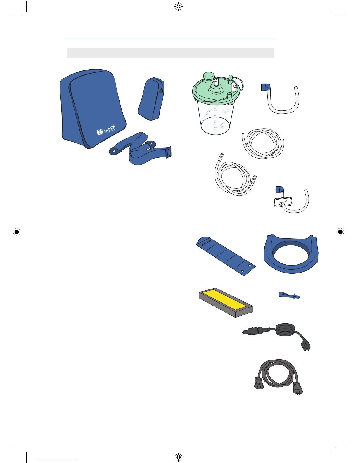
Catalogue
Number Description
78 00 20 01 LSU w/Bemis Canister (not illustrated)
Consumables
88 30 00 Disposable Bemis Canister & Suction
Tubing (12/pkg.)
78 04 12 Disposable Patient Tubing
78 04 22 Coaxial Vacuum Connector, 33 cm, 10 pack
79 46 02 Disposable Patient Tubing w/o tip
78 04 13 34 High Efficiency Filter kit, Coaxial, 37 cm
79 19 00 LSU 12V Socket Adapter
(to convert DIN plug to
standard US 12V accessory plug) Not illustrated.
Accessories
78 20 00 Carrying Bag (full covering)
78 26 00 Wall Bracket w/DC-Power Cord
(not illustrated)
78 26 10 Wall Bracket w/AC-Power Cord US
(not illustrated)
78 26 40 Wall Bracket w/o Power Cord
(not illustrated)
78 23 00 Shoulder Strap
78 24 00 01 Side Pouch
78 04 40 External charger kit (not illustrated)
Parts
78 04 20 Bemis Canister Holder
78 04 33 Strap for Tubing
78 04 32 Release Arm
78 02 00 DC-Power Cord
78 02 10 AC-Power Cord US
78 08 00 LSU Battery - NiMH
78 04 34 Hook for strap (not illustrated)
Note: Parts or product configurations are subject to change without notice.
20
8. Parts List
78 20 00
78 24 00
78 23 00
88 30 00
79 46 02
78 08 00
78 02 00
78 04 33
78 04 32
78 04 20
78 04 13 34
78 02 10
78 04 12
78 04 22
Page 21
21
9.1 Classification
Electrically powered medical suction equipment for field and transport use, according to
ISO10079-1.
High vacuum/high flow.
The LSU is designed for use in road ambulances in accordance with IEC 60601-1-12.
Not suitable for use in the presence of flammable liquids or gases.
Internally powered/class ll equipment type BF, according to IEC 60601-1.
Protection class IP34*, according to IEC 60529.
* - Protected against solid foreign objects of 2.5 mm Ø and greater.
- Protected against splashing water.
- Protected against access with a wire.
MEDICAL ELECTRICAL EQUIPMENT needs special precautions regarding EMC and needs to be installed and
put into service according to the EMC information provided in the accompanying documents.
Portable and mobile RF communication equipment can affect MEDICAL ELECTRICAL EQUIPMENT.
Warning:
MEDICAL ELECTRICAL EQUIPMENT should not be used adjacent to or stacked with other equipment. If
adjacent or stacked use is necessary, the MEDICAL ELECTRICAL EQUIPMENT should be observed to verify
normal operation in the configuration in which it will be used.
9.2 General tolerance
Overall tolerance 5%
9.3 Physical Characteristics
Size: 315 mm (12.4 in) x 330 mm (13 in) x 160 mm (6.3 in), (h x w x d).
Weight: 3.7 Kg (8.2 lbs) including NiMH battery.
Canister: Shipped with BEMIS HI-FLOW Suction Canister, 1200cc (ml).
Patient Suction Tubing
(non-sterile): 0.25 in (6.5 mm) inside diameter x 72 in (1.8 m) length.
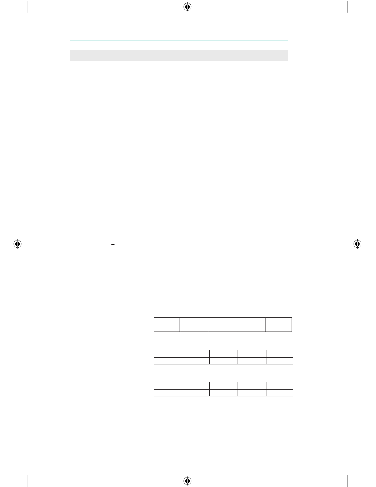
9.4 Operation
Approx. free air flow at
different settings:
l = litre at standard atmospheric pressure and temperature.
Approx. battery
operation time at
different settings:
(free air flow) (±10%)
Approx. noise levels at
different settings:
(free air flow)
Vacuum - Max.: > 500 mmHg (67 kPa).
Vacuum - Range: 80 - 500+ mmHg (11 - 67 kPa).
Vacuum Indicator accuracy: +/- 5% of full scale.
+
80 mmHg 120 mmHg 200 mmHg 350 mmHg 500+mmHg
12 l/min. 16 l/min. 20 l/min. 25 l/min. > 30 l/min.
80 mmHg 120 mmHg 200 mmHg 350 mmHg 500+mmHg
3 h 45 min. 2 h 1 h 20 min. 50 min. 30 min.
80 mmHg 120 mmHg 200 mmHg 350 mmHg 500+mmHg
46 dBA 48 dBA 51 dBA 55 dBA 57 dBA
9. Specifications
Page 22

9.5 Power Requirements
Operating/charging: 100-240 VAC, 50-60 Hz, or 12-28 VDC.*
Battery: 12 VDC 2 Ah, NiMH, rechargeable.
Charging Time: 3 hours for approx. 80% battery capacity, 4 hours for
fully charged.
Vehicle Supply: 12-28 VDC nominal.
Fuses: The LSU fuses must be replaced by a Laerdal Service center.
(See section 6).
Supply Mains: When the unit is connected to SUPPLY MAINS through one
of its power cords, SUPPLY MAINS voltages are present within
the unit. To isolate the unit from SUPPLY MAINS, disconnect
the unit from the power cord, or disconnect the power cord
from SUPPLY MAINS. If placed in a mounting bracket, disconnect
the unit from the mounting bracket.
*The external AC power source must be able to deliver a current of 1A minimum and the external
DC power 5A minimum (LSU has an internal fuse for polarity protection), if not the LSU may switch to
battery operation.
Warning:
The use of accessories, transducers and cables other than those specified, with the exception of transducers and cables sold by the manufacturer of the LSU as replacement parts for internal components, may
result in increased emission or decreased immunity of the LSU.
9.6 Environmental Conditions
Operating/Charging Temperature: 0 °C (32 °F) to + 40 °C (104 °F)
Recommended Charging Temperature: 15 °C (59 °F) to + 25 °C (77 °F )
Long Term Storage Temperature: 0 °C (32 °F) to + 40 °C (104 °F)
Max. 24 hour Storage Temperature: -30 °C (-22 °F) to +70 °C (158 °F)
The time required for the LSU to warm from the mini
mum storage temperature between uses until it is ready
for intended use is min 90 minutes at room temperature.
The time required for the LSU to cool from the maxi
mum storage temperature between uses until it is ready
for intended use is min 90 minutes at room temperature.
Humidity (Operating & Storage): 5-95% RH non-condensing
Altitude 0 - 4000 m
9.7 Material Chart
Cabinet front: Poly Carbonate/Acrylonitrile Butadiene Styrene
(PC/ABS)
Protector for front: Styrene Ethylene Betyl Styrene (SEBS)
Cabinet back: PC/ABS
Cabinet base w/Protector: PC/ABS + SEBS
Battery door: SEBS
Connector retainer for battery: Poly Oxy Methylene (POM)
Operating Knob: POM
Rotor for Vacuum Switch knob: PC/ABS
Manifold for vacuum: POM
Canister Holder: Polypropylen(PP)
Handle w/Protector: PC/ABS + SEBS
Manifold for exhaust: POM
Strap for patient suction tubing: SEBS
Canister Holder Release Arm: POM
User Interface Polyester
Vacuum Connector: Silicone
Vacuum Connector Tubing: Silicone
Disposable Canister: General Purpose Polystyrene (GPPS)
Disposable Canister Lid: High-Densisty Polyethylene (HDPE)
Patient Suction Tubing: Polyvinylchloride “flexible” (PVC)
Wall bracket: Aluminium + Steel + POM + PE + PVC
Full covering Carrying Bag: PVC coated Polyester
Side Pouch: PVC coated Polyester
22
Page 23
23
9.7.1 Dismantling/Disposal
When discarding the LSU, we recommend it be dismantled and discarded according to local protocol.
Dismantle the LSU by unscrewing the screws on the back side of the LSU, remove the components and
sort according to the table in 9.7. The cleaned LSU can also be delivered to your local Laerdal Medical
representative for dismantling/disposal. Laerdal Medical AS will not charge any fee for the dismantling;
Sender is responsible for the cost of the shipment.
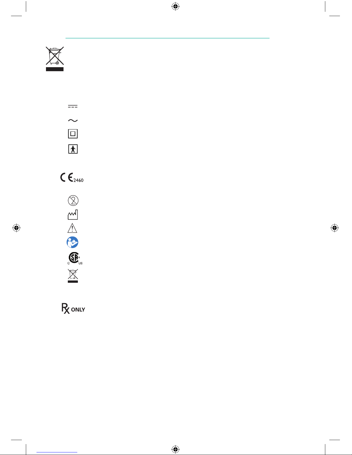
9.8 Symbols
Direct Current
Alternating Current
Class II Equipment, according to IEC 60601-1
Type BF applied part, according to IEC 60601-1
IP34 Protection class ref. IEC 529
This product is in compliance with the essential requirements of MDD 93/42/EEC as
amended by Council directive 2007/47/EC and Council directive 2011/65/EU relating to
restriction on the use of certain Hazardous Substances (RoHS 2)
Do not reuse
Date of production
Warning/Caution
Consult User Guide
The products is eligible to bear the CSA Mark with adjacent indicators ‘C’ and ‘US’ for
Canada and US
This appliance is marked according to the European directive 2012/19/EC on Waste
Electrical and Electronic Equipment (WEEE). The symbol on the product, or on the documents accompanying the product, indicates that this appliance may not be treated as household waste. Instead it shall be handed over to the applicable collection point for the recycling
of electrical and electronic equipment
Caution: Federal law (USA) restricts this device to sale by or on the order of a physician
Page 24
24
Electromagnetic Conformity
Laerdal Suction Unit is intended for use in the following environments: Professional
Healthcare Facility environment and Emergency Medical Services environment.
Essential performance of the LSU is identified as connection of the patient hos to
the exhaust outlet must be prevented by coding of the outlet and identifying the
exhaust using a label on the device. EMC disturbances cannot affect this behavior.
No particular actions are required to maintain safety and performance with
regard to electromagnetic disturbances for the expected service life.
Warning
Use of this equipment adjacent to or stacked with other equipment should be avoide
because it could result in improper operation. If such use is necessary, this equipment
and the other equipment should be observed to verify that they are operating normally.
Warning
Use of accessories, transducers and cables other than those specified or provided
by the manufacturer of this equipment could result in increased electromagnetic
emissions or decreased electromagnetic immunity of this equipment and result in
improper operation.
Warning
Portable RF communications equipment (including peripherals such as antenna
cables and external antennas) should be used no closer than 30 cm (12 inches) to
any part of the LSU, including cables specified by the Laerdal Medical. Otherwise,
degradation of the performance of this equipment could result.
Page 25
25
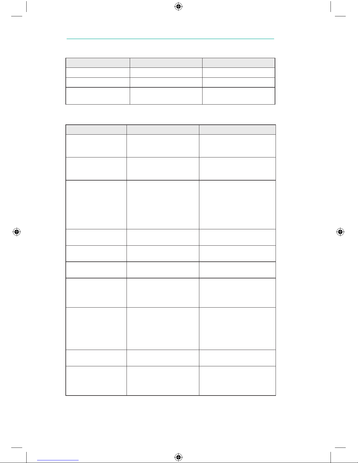
Electromagnetic Emissions Tests
Emissions Test Standard or test method Compliance
RF emissions CISPR 11 Group 1 Class B
Harmonic emissions IEC 61000-3-2 Class A
Voltage fluctuations/
flicker emissions
IEC 61000-3-3 Complies
Electromagnetic Immunity Tests
Immunity Test Standard or test method Compliance Level
Electrostatic discharge IEC 61000-4-2 ± 8 kV contact
± 2 kV, ± 4 kV, ± 8 kV, ± 15
kV air
Radiated RF EM fields IEC 61000-4-3 3 V/m
80 MHz – 2.7 GHz
80 % AM at 1 kHz
Proximity fields from RF
wireless communications
equipment
IEC 61000-4-3 380-390 MHz: 27 V/m
430-470 MHz: 28 V/m
704-787 MHz: 9 V/m
800-960 MHz: 28 V/m
1700-1990 MHz: 28 V/m
2400-2470 MHz: 28 V/m
5100-5800 MHz: 9 V/m
Rated power frequency
magnetic fields
IEC 61000-4-8 30 A/m
50 Hz or 60 Hz
Electrical fast transients /
bursts, AC power port
IEC 61000-4-4 ± 2 kV
100 kHz repetition frequency
Surges: Line-to-line,
AC power port
IEC 61000-4-5 ± 0.5 kV, ± 1 kV
Conducted disturbances
induced by RF fields, AC
power port
IEC 61000-4-6 3 V; 0.15 MHz – 80 MHz
6 V in ISM bands between 0.15
MHz and 80 MHz
80 % AM at 1 kHz
Voltage dips,
AC power port
IEC 61000-4-11 0 % UT; 0.5 cycle
At 0°, 45°, 90°, 135°, 180°,
225°, 270° and 315°
0 % UT; 1 cycle and 70 % UT;
25/30 cycles
Single phase: at 0°
Voltage interruptions,
AC power port
IEC 61000-4-11 0 % UT; 250/300 cycle
Electrical transient
conduction
along supply lines, DC
power port
ISO 7367-2 Test pulse severity level: III in
Table A2 of ISO 7637-2
Page 26

Page 27

Page 28

© 2017 Laerdal Medical AS. All rights reserved.
Made in Norway by:
LAERDAL MEDICAL AS
P.O. Box 377, Tanke Svilandsgate 30
4002 Stavanger, Norway
Tel. +47 51 51 17 00
Fax +47 51 52 35 57
Distributed in USA by:
LAERDAL MEDICAL CORPORATION
167 Myers Corners Road
Wappingers Falls, NY 12590-8840
Tel. +1 (800) 431-1055, +1 (845) 297-7770
Fax. +1 (800) 227-1143
Printed in Norway
www.laerdal.com
6791 Rev J
 Loading...