

Page 1

SimMan 3G
Trauma
User Guide
EN
www.laerdal.com
Page 2

Page 3

CONTENTS
INTRODUCTION 4
SimMan 3G Trauma Patient Simulator 4
CAUTIONS AND WARNINGS 5
General Simulator Handling 5
Antivirus and Firewalls 5
File Security and Backup of Data 5
FEATURES 6
SimMan 3G Trauma Overview 6
General 7
Laerdal Simulation Software 7
Airway Features 8
Breathing Features 9
Circulation 10
Bleeding 10
Sounds 11
Eyes Settings and Configurations 11
Drugs and IV 11
SimMan 3G Trauma Clothing 12
SETUP 13
Inserting and Connecting the Batteries 13
The Power Panel 14
Charging the Batteries 14
Battery Use 15
Battery Warnings 16
Using the Internal Compressor 16
Turning the Internal Compressor OFF Using LLEAP 16
Changing Default Compressor Settings Using LLEAP 16
Air/CO
Panel 17
2
Blood and Fluid System 17
Adjusting Fluid Flow 19
Connecting Wounds Kit 20
Removing Wounds 20
Simulate Severe Bleeding Using LLEAP 20
Administering IV Fluids 21
Cleaning the IV Arm 21
Connecting Defibrillation Adapter Plates 22
Connecting the Blood Pressure Cuff 23
Calibrating the IV Arm Flowmeter Using LLEAP 23
Connecting the SpO
Changing Genitalia Modules 24
Probe 23
2
Inserting Urine Catheter 24
Changing the Upper Dentures 24
Bleeding Modules 25
Replacing and Filling IO Units with Blood 29
Transporting SimMan 3G Trauma 32
Unpacking the Patient Simulator 32
MAINTENANCE 33
Daily Maintenance 33
Before Storage or Shipping 33
Regular Cleaning of Fluid and Blood System 33
Installing and Upgrading LLEAP 35
Removing/Changing Router 35
Opening the Torso 36
Attaching the Left Leg 36
Attaching the Right Leg 37
Attaching the Left Arm 37
Attaching the Right Arm 38
Replacing Crico Tape/Neck Skin 38
Replacing Chest Drain Pleura 39
Replacing Pneumothorax Bladders 39
Replacing Chest Rise Bladder 40
Replacing Lung Bladders 40
Replacing Simulator Skins 41
Replacing Blood System Filter 41
Servicing the Patient Simulator 41
TROUBLESHOOTING 42
SPARE PARTS AND ACCESSORIES 45
3
3
Page 4

INTRODUCTION
SimMan 3G Trauma Patient
Simulator
For Advanced Clinical Simulation
SimMan 3G Trauma is an advanced patient simulation system that
facilitates training of Basic and Advanced Life Support. The system
allows the instructor to effectively assess the learner’s individual and
team skills based on a realistic clinical situation.
SimMan 3G Trauma allows observation and recognition of most
vital signs. This is achieved through direct interaction with the Patient
Simulator and observation of the Patient Simulator’s status as viewed
on the Patient Monitor.
The SimMan 3G Trauma Simulation System
Features Include:
– An advanced configurable airway, comprised of adjustable lung
compliance and resistance - allowing simulation of difficult airway
management cases.
– Eyes that respond to light and react according to the clinical
state of the Patient Simulator.
– Bleeding and Wound Modules are fed from an internal blood
reservoir. An external Blood Fill Unit may be connected for
extended bleeding cases.
– Simulated Secretions: sweat, tears, froth, urine and ear fluids are
fed from an internal fluid reservoir. An external Fluid Fill Unit
may be connected for extended use.
– Focus on Quality CPR (QCPR): measurement and feedback
according to the 2005 and 2010 Guidelines.
– Vascular Access (intra osseous) via the tibia and sternum.
– Automatic Simulation Control based on preprogrammed and
validated Patient Cases.
WLAN Communication
Communication between the Patient Simulator and the PCs is based
on WLAN communication. The Patient Simulator and PCs can also
be connected to a LAN cable network, and WLAN disabled.
The Main Components of the SimMan 3G
Trauma System:
SimMan 3G Trauma is an adult life-size wireless Patient Simulator,
with internal battery power, internal air compressor and fluid
reservoirs. Interventions by learners are registered by the system in
the session log, and used for later debriefing.
The Instructor PC controls the simulation. The headset allows the
instructor to simulate interactive voice communication between the
patient and the learner.
Software available for use with the simulator includes LLEAP for
controlling scenarios, SimDesigner for creating and editing scenarios,
SimView server or SessionViewer for debriefing simulation sessions
with video capture and a Patient Monitor application.
4
Page 5

CAUTIONS AND WARNINGS
General Simulator Handling
The Patient Simulator should be operated by trained personnel only.
Treat the Patient Simulator as you would treat a real patient.
Warning: Do not ventilate the Patient Simulator with oxygen
enriched air or flammable gases.
− Do not introduce fluids into or onto the Patient Simulator
(except as directed in the User Guide), as this may damage the
Patient Simulator and it’s components.
− Do not introduce humidified air into the system during
ventilation.
− Never perform mouth-to-mouth or mouth-to-nose rescue
breathing on the Patient Simulator. The simulator’s airways are
not designed for cleaning or disinfection.
− Do not use the Patient Simulator if the internal tubing and
cabling is disconnected.
− Never use the Patient Simulator outdoors in wet conditions, as
this may pose a shock hazard or damage the simulator.
− Never use the Patient Simulator in temperatures exceeding 40°
C (104°F), as this may cause overheating and shut down.
− Never use the Patient Simulator in temperatures below 4 °C (39
°F), as this may damage the fluid system.
− The Patient Simulator should never be stored in temperatures
below -15° C (5° F).
− The Patient Simulator will automatically shut down if the battery
temperature exceeds 60°C (140°F).
− Using a defibrillator in temperatures over 35° C (95° F) may
cause overheating and shut down.
Warning: Avoid pinch hazards - Do not remove protective bushings
from the Patient Simulator’s joints or use it without the external skins.
Warning: Avoid all sharp edges on the Patient Simulator to prevent
personal injury.
Do not use the Patient Simulator if:
− Limbs are not attached to the torso
− Skins are torn or not properly fastened
− Internal or external cables, tubes or connectors are damaged
− There is fluid leakage inside the Patient Simulator torso
− There are unusual sounds indicating air leakage or mechanical
damage
− There are signs of electrical malfunction, such as an unresponsive
Patient Simulator or unusual smell or smoke
Hygiene
– To maintain Patient Simulator skins, wash hands before use and
place the Patient Simulator on a clean surface.
– Wear gloves as required during simulation scenarios.
– After using the Fluid and Blood System, follow the cleaning
instructions (see Maintenance section).
– After using the SimMan 3G Trauma Wound Kit, remove glue
residue from the Patient Simulator skin with Laerdal Medical
Wipes.
– Use only Laerdal Airway Lubricant in the Patient Simulator’s
airway. Do not spray airway lubricant into the Patient Simulator.
Lubricate tools only.
Prevent Stains on Patient Simulator Skins
Avoid using colored plastic gloves, as they may cause discoloration of
the Patient Simulator skin.
Do not use felt-tipped markers, ink pens, acetone, iodine or other
staining medications near the Patient Simulator. Take care not to
place the Patient Simulator on newsprint or colored paper. All
staining may be permanent.
Transportation and Storage
SimMan 3G Trauma is heavy; ensure that the Patient Simulator is
properly secured during transportation to prevent personal injury or
damage to the product.
Antivirus and Firewalls
The Patient Simulator and PCs are not supplied with Antivirus
programs. Windows firewall is activated by default. It is the
customer’s responsibility to protect the simulation system
components from unauthorized access.
The Patient Simulator will revert to factory settings each time the
power is switched off.
The customer should install all recommended Windows updates
from Microsoft. General security measures should be taken before
browsing the internet.
It is recommended that the SimMan 3G Trauma PCs are used
only as Patient Simulator controllers. Downloading other software
programs onto these machines may introduce unexpected errors.
File Security and Backup of Data
The customer is responsible for file security and backup routines for
all simulation session data. All use and storage of simulation session
data should be in accordance with local rules, regulations or laws,
and is the sole responsibility of the customer.
Cautions and WarningsFeaturesSetupMaintenanceSpare Parts Troubleshooting
5
Page 6
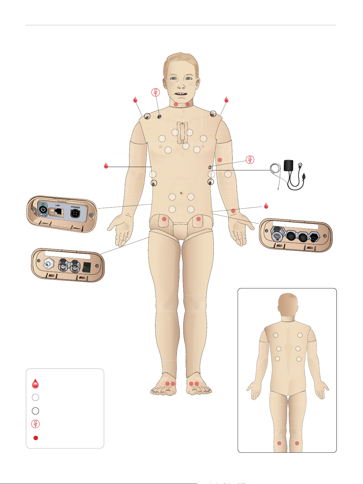
DC Input 9-24V X, XA
FEATURES
SimMan 3G Trauma Overview
Power Panel
Air Out
Fluid Fill Panel
Bleeding ports
Speakers
Air / CO
2
Inlet
Blood
Fluid
Inlet
Activate
Inlet
Filling
Air/CO2 Panel
Blood
Outlet
ECG Connectors
Defib Connectors
Pulses
6
Page 7
FEATURES
General
Main Anatomical Features
Dimensions (Patient Simulator only):
1800mm (l) x 550mm (w) chest (5. 90 ft x 1.80 ft)
Weight (Patient Simulator only): 38.5kg (85 lbs)
Weight (with clothes): 40 Kg (88 lbs)
Default male body with interchangeable genitalia pads.
Configurable Anatomical Features
Genitalia
The Patient Simulator comes with a neutral genitalia pad as default.
The pad can be changed for a male or female module, both included
with the SimMan 3G Trauma System. See Changing Genitalia Modules
section.
Teeth
Patient Simulator comes with a set of soft teeth as default. These can
be exchanged for a hard set of teeth, included with the SimMan 3G
Trauma System. See Changing Upper Dentures section.
Trauma Modules/Limbs
Left Leg - amputation and bleeding module
Right Arm - amputation and bleeding module
The SimMan 3G Trauma arm adaptor kit is used to connect the
trauma arm modules.
Contact your local Laerdal representative to enquire about other
trauma modules compatible with SimMan 3G Trauma.
Laerdal Simulation Software
To run a simulation, LLEAP (Laerdal Learning Application) must be
started from Laerdal Simulation Home on the Instructor PC.
Cautions and WarningsFeaturesSetupMaintenanceSpare Parts Troubleshooting
Laerdal Simulation Home
Laerdal Simulation Home is an application from where LLEAP and
other Laerdal programs related to patient simulation can be found
and started. The help files can also be opened from here. Laerdal
Simulation Home is located in the Laerdal Medical folder under the
Windows start menu (Windows 7).
Software used in a simulation session comprises the following main
applications:
− LLEAP (Laerdal Learning Application)
− Voice Conference Application
− Patient Monitor
− SimView Ser ver or Session Viewer
In addition SimDesigner and other applications are also used for
designing or preparing a simulation.
LLEAP
LLEAP is the instructor’s application from where the simulation
session is run, controlled and monitored. LLEAP can be operated
in Automatic or Manual mode. Automatic mode is used for
preprogrammed scenarios while Manual mode allows the instructor
full manual control of the simulation session. Running simulations in
Manual Mode requires some medical expertise to create clinically
sound simulations.
Mobility of joints
Neck: Movement can be on a 3-axis movement of head.
Range of movement can be restricted. See Airway
Features section.
Shoulders: 3-axis rotation
Lumbar: 1-axis
Elbows: Fixed, no mobility
Wrists: 3-axis rotation
Thumbs: Free mobility
Hip joints: 3-axis rotation
Knees: 1-axis rotation
Ankles: 1-axis rotation
Note: Do not remove protective bushings at shoulder or lower back.
These are present to protect users from pinch points.
Voice Conference Application (VCA)
The VCA software allows the instructor to communicate through
the simulator during the session. VCA can also be used to
communicate with other instructors on a network, and create
separate channels where only members can communicate.
Patient Monitor
The Patient Monitor application emulates a typical hospital patient
monitor. It is the learner’s console and can be set up and controlled
by the instructor, as well as by the learner through on-screen touch
menus.
Session Viewer and SimView Server
Session Viewer and SimView Server are applications that record
video and patient monitor screen captures during simulation, in
addition to providing an interface to debrief your session. After a
session is ended, log files generated in LLEAP are transferred and
merged with the video files in Session Viewer or SimView Server for
the debrief.
Session Viewer typically runs locally on the same computer as used
for LLEAP, SimView Server runs on a dedicated ser ver in the local
network. During the first startup of LLEAP, you are prompted to
select a debriefing system available on your computer or on a local
network. This can be changed later.
7
Page 8

FEATURES
Other Applications
There are also other programs that are used in conjunction with
the simulation sessions, for example License Manager for handling
program licenses and Simulator Firmware & Network Wizard for
updating the firmware of the simulators or troubleshooting network
problems.
SimDesigner
The SimDesigner application allows you to configure your own
preprogrammed scenarios. It can also be used to analyze and print
out a graphical representation of a scenario.
SimDesigner must be installed to allow conversion of legacy
instructor application files to LLEAP compatible file formats.
For a full overview of all applications and their help files, start LLEAP
Simulation Home.
Web Downloads
Visit www.laerdal.com/download to download the latest User Guide
and Software.
Airway Features
The airway is anatomically modeled as far as the bronchia.
The airways can be manipulated by a learner:
− Head tilt/Chin lift
− Jaw thrust with articulated jaw
− Cricoid pressure and manipulation
− Suctioning (oral & nasopharyngeal)
If the tongue fallback feature is enabled, head tilt is required to open
the airways for mask ventilations. The Patient Simulator may be
ventilated by normal and emergency methods:
Use of a malleable stylet is recommended - make sure it does not
extend beyond the ET tube.
Recommended styles:
− i-Gel
− Fiberoptic intubation
− Combitube (size small adult is suitable)
− Retrograde intubation
− Needle cricothyrotomy
− Surgical cricothyrotomy
The following Patient Simulator features indicate incorrect
tube placement:
− Right main stem intubation – unilateral chest rise
− Stomach distention
− Lack of chest sounds, CO
section)
exhalation (see Breathing Features
2
Configurable Airway Features
Patient Simulator features may be configured to present various
airway scenarios:
− The airway may be closed automatically or manually. There are
four levels of resistance and compliance within the airway.
− Tongue edema - multiple levels
− Phar yngeal swelling
− Lar yngospasm
− Decreased cer vical range of motion
− Trismus
− Teeth - soft upper dentures may be replaced with a hard set of
teeth for enhanced realism while practicing intubations.
− Bag-mask ventilation
− Orotracheal intubation
− Nasotracheal intubation
− Transtracheal intubation
Prior to using airway adjuncts, apply a small amount of Laerdal
Airway Lubricant to the equipment. Do not spray lubricant directly
into the airway,
The following equipment or methods are suitable to secure
the Patient Simulator’s airway:
− Lar yngeal mask airways: The airways are designed for use with
size #4, but size #5 may also seal correctly.
− Endotracheal tube intubation, Size ID 7.5 - 8.5 is suitable, but
using the smaller size reduces wear of the Patient Simulator’s
airways.
During simulation, the following conditions can be set:
− Can’t intubate/can ventilate
− Can’t intubate/can’t ventilate
The following information is automatically registered in the
SimMan 3G Trauma simulation session:
− Detection of proper head position.
− Jaw Thr ust
− Pneumothorax decompression
− Ventilations
− Stomach distension
Note: In LLEAP the airway and breathing status for the current
simulator is shown in a window. Settings for lung resistance,
compliance, and other parameters can be made. See LLEAP Help
for further information.
8
Page 9
FEATURES
Breathing Features
The SimMan 3G Trauma can simulate spontaneous breathing:
− Bilateral and unilateral chest rise and fall
− There are 4 compliance settings, from normal to extremely stiff
− There are 4 settings for airway resistance, from normal to
extremely tight.
− Normal and abnormal breath sounds
− 5 anterior auscultation sites and 6 posterior auscultation sites
− Unilateral, bilateral and lobar breath sounds
− Oxygen saturation and phlethysmogram
− CO
Patient Monitor features - Breathing
− SpO
− Airway respiration rate (awRR)
− End-tidal CO
− End-tidal O
− inO
− pH
exhalation for use with third-party End-tidal CO2 detectors
2
(Requires connection to an external CO
Warning: Do not ventilate the Patient Simulator with oxygen
enriched air or flammable gass.
Caution: Do not ventilate Patient Simulator lungs using humidified
air.
2
(etCO2)
2
(etO2)
2
2
reservoir)
2
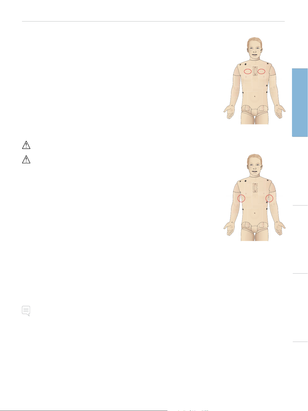
Pneumothorax
Tension pneumothorax with
needle decompression can be
performed at bilateral mid
clavicle line, 2nd intercostal
space. The pneumothorax
bladders may be pierced +/-10
times, the pressure inside the
bladder will drop after repeated
puncturing.
A 22 (or smaller) gauge
needle is recommended for
decompression of the chest.
Using a smaller gauge needle
increases the longevity of the
chest skin and bladders.
However, a too small gauge prevents automatic detection of the
decompression event in the simulation model.
Chest Tube Inser tion
Chest tube insertion can be
simulated. Exploration and cut
can be made at left or right
mid-axillary line in the 4th and
5th intercostal space.
Cautions and WarningsFeaturesSetupMaintenanceSpare Parts Troubleshooting
Lung specifications
− Max tidal volume: 1.2 liters
− Max tidal volume registered in the LLEAP is 900ml. All volumes
higher than 900ml will register as 900ml
− Max airway pressure: 80 cm H
− Simulated stomach inflation star ts from approximately 40cmH
airway pressure.
Note: Lungs are not intended for use with PEEP-valves.
O
2
O
2
9
Page 10
FEATURES
Circulation
Cardiac features
− Extensive ECG library, pulses from 0-220.
− Hear t sounds - for every anterior location
− ECG rhythm monitoring (4-connector, 3-lead ECG)
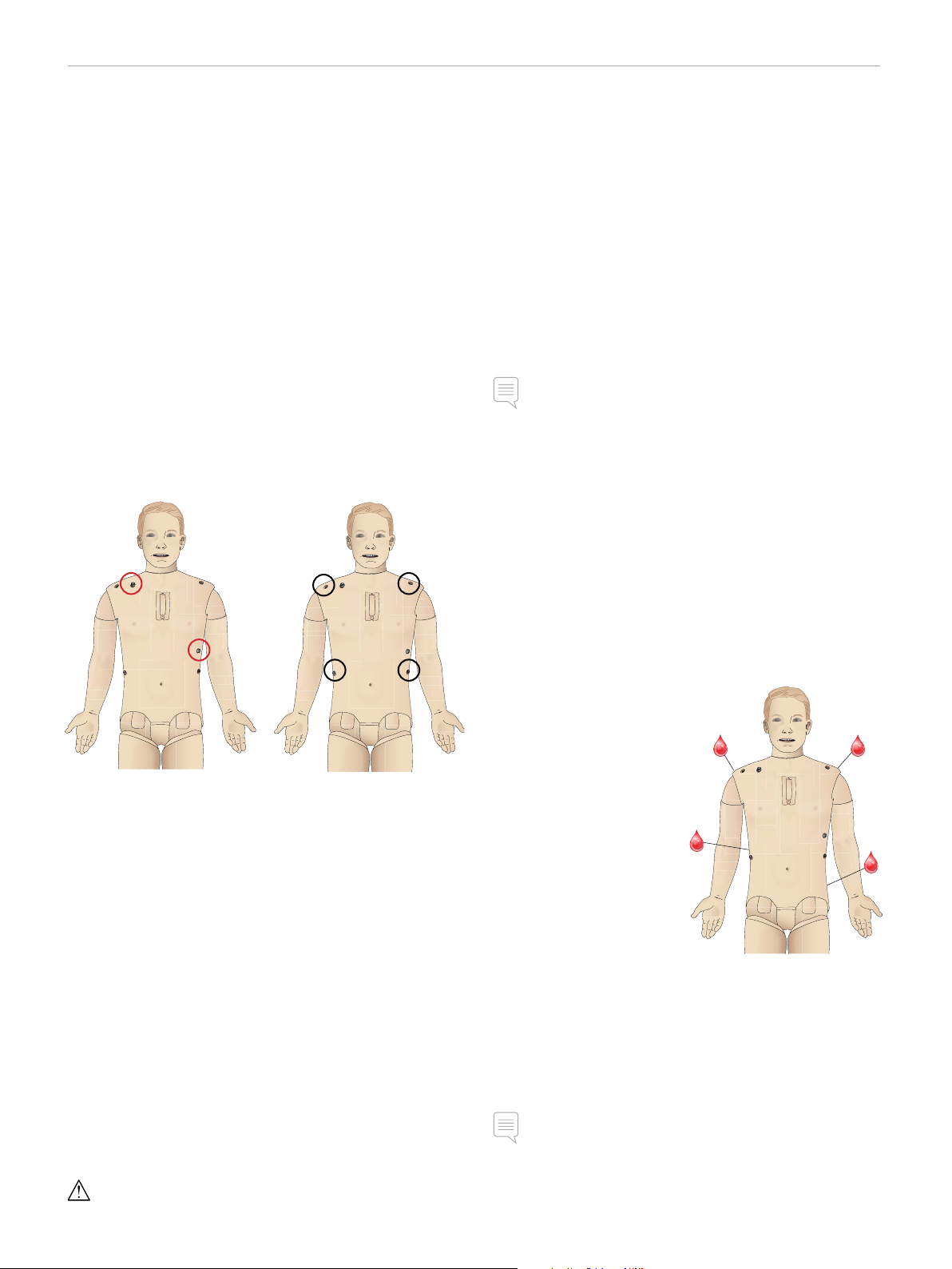
− 12-lead ECG display
− Pacing
− Defibrillation and cardio version using live defibrillators
Defibrillation
− With live defibrillators; energy level and waveform model is
registered by the Patient Simulator.
− The energy levels and number of shocks required for automatic
conversion are set in each simulation Patient Case.
Defibrillation Studs 3-Lead ECG Studs
Patient Monitor features - Circulation
− ECG (12-lead) and hear t rate (HR)
− Pulse
− NBP
− ABP
− PA P
− C .O.
Patient Monitor features - Temperatures
− TPeri
− Tblood
Note: A variety of settings in the Circulation and Fluids window can
be made in LLEAP. See LLEAP Help for further information.
Bleeding
To allow the Patient Simulator to bleed realistically, it has internal
reservoirs for simulated blood. See Blood and Fluid System section.
The four bleeding ports and blood flow can be adjusted
independently from LLEAP:
− Upper and lower bleeding ports
− Venous and arterial
− Works with various wound modules and moulage kits
Circulation features
− BP measured manually by auscultation of Korotkoff sounds
− Carotid, brachial, radial, femoral, popliteal, dorsalis pedis, and
posterior tibialis pulses synchronized with ECG
− Pulse strength variable with BP
− Pulses are synchronized with ECG when the instructor sets the
pulse strength manually
− Pulse palpation is detected and logged
CPR
− Compliant with 2005 and 2010 Guidelines
− Compressions generate palpable pulses, blood pressure wave
form, and ECG artifacts
− Realistic compression depth and resistance
− Detection of depth, release and frequency of compressions
− Real-time view of Quality of CPR on the Instructor’s PC
Warning: Do not use automated chest compression machines on
the Patient Simulator.
Bleeding Treatment:
− Bandage
− Pressure point
− Tourniquet
− Surgical Clamps
Vascular Access:
− IV access (right arm)
− Intraosseous access (tibia
and sternum)
Consumables and
Spare Parts:
− Laerdal Ar tificial Blood
− Fill Units
− Wound modules
− Replacement trauma arm/leg.
Note: A variety of settings in the Circulation and fluids window can
be made in LLEAP. See LLEAP Help for further information.
10
Page 11
FEATURES
Sounds
Two types of sounds can be used in a scenario:
– Body sounds
– Vocal sounds
The sounds can be triggered by the scenario or controlled by the
instructor.
Body Sounds
The body sounds are simulated sounds from a human body, like
heart, lungs, and bowel sounds. The sounds are integrated and
generated in the Patient Simulator and transferred through the
integrated speakers.
Vocal Sounds
The vocal sounds are sounds from the throat like coughing, moaning,
and crying as well as spoken words. The sounds are integrated in
LLEAP and transferred to the Patient Simulator.
In addition, the instructor can communicate through a microphone
and the voice is then transferred to the Patient Simulator through
the VCA.
Note: A variety of settings in the Sounds window can be made in
LLEAP. See LLEAP Help for further information
Drugs and IV
Drugs and drug concentrations can be registered manually by the
instructor in LLEAP.
Patient Monitor features – Drugs
– Train-of-Four (TOF)
– in N
O, et N2O
2
– Anesthesia agents
– Lab reports
User-replaceable items, spare par ts
– Intra-muscular Pad x 3
– Sternal IO Pad
– Tibial IO Pad
Vascular Access (IV and IO) Locations
Intraosseous access with needle insertion is possible through the
left tibia and the Sternal IO pad. The IO pads may be punctured
numerous times before being replaced.
To replace the IO modules, see Replacing and Filling IO Units with
Blood section.
Cautions and WarningsFeaturesSetupMaintenanceSpare Parts Troubleshooting
Eyes Settings and Configurations
The calculated Glasgow Coma Scale score for the Patient Case is
displayed in LLEAP. The following sources of information help the
learner to judge the state of disability:
Eyes
– Blinking eyelids
– Eyelids: open, closed or partially open
– Eyelids can be opened for examination by the learner
– Pupil dilation: constricted, dilated or in between
– Pupillary accommodation
– Synchrony/asynchrony
– Normal and sluggish speed of response
Note: A variety of settings in the Circulation and Fluids window can
be made in LLEAP. See LLEAP Help for further information.
Caution: Do not inject fluids into these pads unless approved IO
modules with fluid outlets are in place.
Intra-muscular (IM) Injection
Use the pad placed under the Torso Skin on the right buttock for
intramuscular injection training. Use the tigh pads (left and right) for
IM injection.
11
Page 12

FEATURES
SimMan 3G Trauma Clothing
Included with the Patient Simulator:
− Shir t, with side zippers
− Trousers, with full-length side zippers
− Boxer shorts underwear
− Belt
Note: For washing instructions see care labels.
Simulated Removal of the Clothes
To simulate cutting with scissors: unzip the zippers placed alongside
the seams on both sides.
12
Page 13
SETUP
Inserting and Connecting the
Batteries
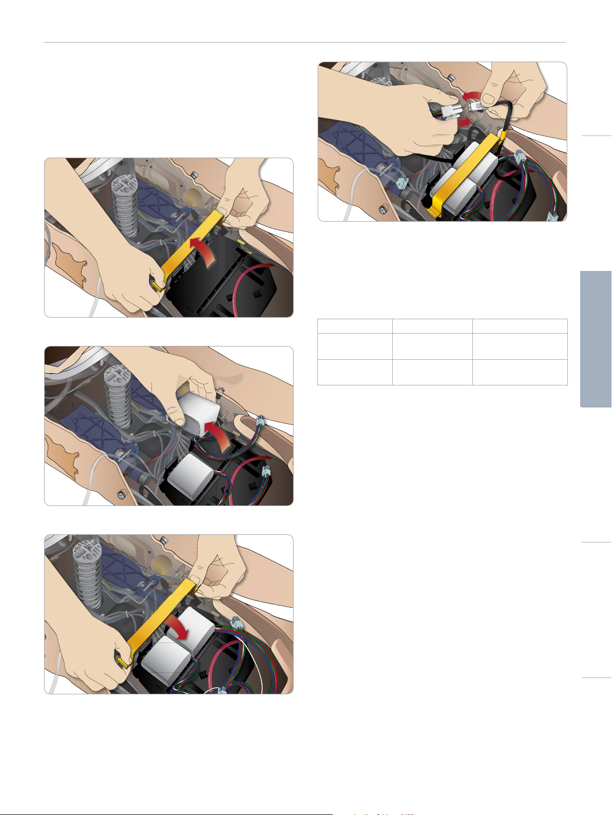
Open the torso as described in steps 1 - 4, Opening the Torso.
To remove the batteries, follow the same procedure in reverse.
1 Release the battery clamp by unhooking the clips on either side.
2 Insert both batteries into the battery tray.
Cautions and WarningsFeaturesSetupMaintenanceSpare Parts Troubleshooting
After connecting the batteries, connect the Patient Simulator to the
external power supply (12V to 24V) while turned OFF.
The batteries will charge if the Patient Simulator is ON and
connected to an external power supply in the range of (20V - 24V).
Battery - Cable and Tube Descriptions
Name/Label Tube/Cable Color Connector Description
Battery 1 Black harness cable Black rectangular
connector, 6 lead
Battery 2 Black harness cable Black rectangular
connector, 6 lead
3 Snap the battery clamp back into place over the batteries.
4 Connect the corresponding battery cables from the batteries to
the torso.
13
Page 14
DC Input 9-24V X, XA
POWER
SETUP
The Power Panel
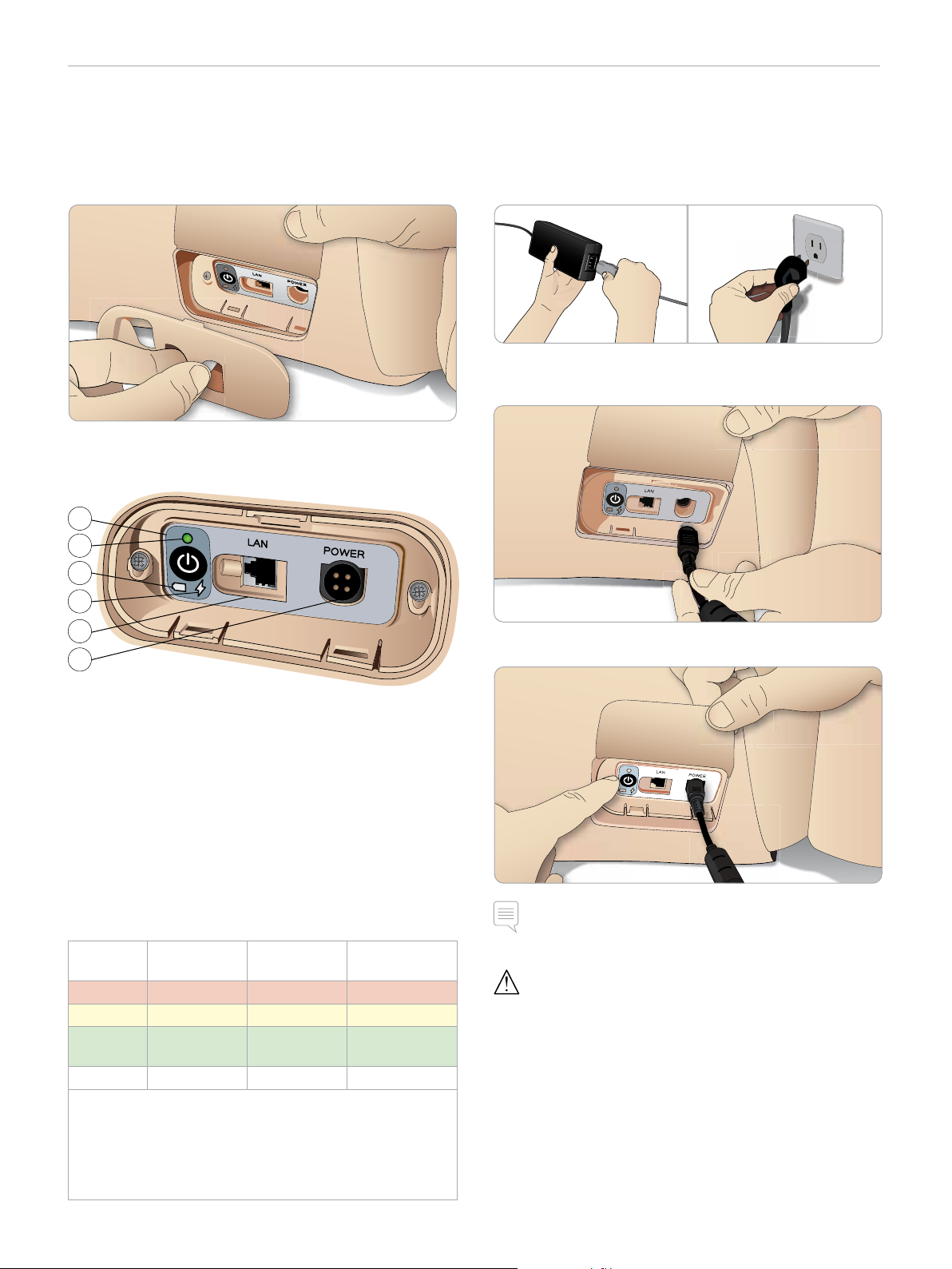
The power panel is found on the right side of the Patient Simulator,
under a loose skin flap. Lift the skin flap and pull out the protective
cover.
To ensure easy access, use the zippered clothing provided with the
Patient Simulator.
1
2
Charging the Batteries
Inside the Patient Simulator
1 Connect the Patient Simulator to the external power supply
with a power cord and plug that meets local specifications.
2 Plug the power supply into a wall outlet and connect the power
cable to the power inlet on the Patient Simulator’s power panel.
3
4
5
6
Power panel overview
1 Power ON / OFF button
2 Power status indicator
3 Battery status indicator
4 Charging status indicator
5 LAN network cable connector
6 External power supply connector
Power Status Indicator Description
Indicator
Light Color
Red Power save* 0% - 20% Not charging**
Yellow Star t up 20% - 70% Charging
Green Running 70% - 100% Charge almost
No light Off Off No charge****
* Blinking light
** One or both batteries missing, overheated, damaged or
otherwise not able to charge
*** Not recommended to charge the batteries too long
**** No power input, batteries are charged.
Power Save is activated whenever Patient Simulator is paused.
Power Status Battery Status Charge Status
complete***
3 Press the ON button to power on the Patient Simulator.
Note: During start up, the Patient Simulator’s eyes will blink and
the power status indicator light will be yellow.
Caution: After Patient Simulator is turned off, wait 20 seconds
before restarting. If not, Patient Simulator may not function properly.
14
Page 15
SETUP
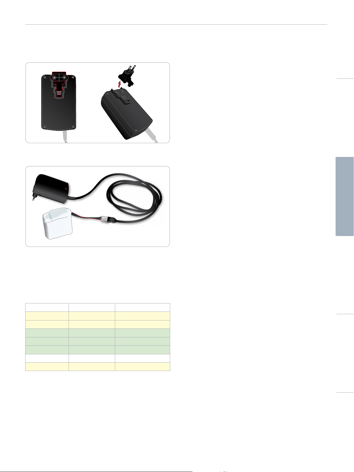
External Battery Charging
The battery charger comes with 5 international plugs. Connect the
appropriate plug to the charger :
1 Connect the charger to a power outlet and connect the Patient
Simulator battery to the charger.
Battery Use
− Always use two batteries to power the Patient Simulator.
− Ensure that the batteries are properly connected.
− Charge the batteries regularly.
− Check LEDs on Patient Simulator’s power panel for battery
status.
– Charge both batteries before the battery charge drops below
15% or the battery light indicator is red. This can be monitored
in the technical status window on the Instructor PC.
– The Patient Simulator will automatically shut down if: batter y
temperature rises above 60°C (140°F) or the remaining charge
falls below 6 % on one of the two batteries.
View Battery Status in LLEAP
Check the power indicator in the Simulator Status window in LLEAP
according to the instructions in LLEAP Help.
Changing Batteries during a Simulation Session:
1 Press <Pause Session> on Instructor PC. Access the batteries as
described in Inserting and Connecting the Batteries.
2 Replace one battery at a time to avoid loss of simulation data.
Cautions and WarningsFeaturesSetupMaintenanceSpare Parts Troubleshooting
2 The indicator light on the battery charger shows charge status.
3 Battery charging time is approximately 6,5 hours.
The external battery charger should only be used with Patient
Simulator batteries.
Charger Indication
Light Code Light Color Characteristic
Standby Yellow Steady
Pre-charge Yellow Normal Flashing
Rapid charge Green Rapid Flashing
Maintain Green Normal Flashing
Ready Green Steady
Wait Alternating Alternating
Error Yellow Rapid Flashing
Storage and Transportation
− Never store fully charged batteries for longer than a month.
− Never store the batteries inside the Patient Simulator.
− Store batteries in a refrigerator i.e. temperature 0°C - 4°C
(32°F - 40°F).
− The two batteries can be transported in the Patient Simulator
during air freight.
− When transporting spare batteries please contact the airline or
freight company for the latest transport regulations.
Battery Maintenance
− On approximately every 30th charge cycle, drain the battery
completely before recharging. To drain the batteries run the
Patient Simulator on both batteries until automatic shut down.
− Expected batter y life: 200 charge cycles.
− Replace only with Laerdal SimMan 3G Trauma batteries.
15
Page 16

SETUP
Battery Warnings
Warning: Do not run the Patient Simulator for more than 1 minute
on a single battery.
Warning: If both batteries are removed while the simulation is
paused, the Patient Simulator will shut down and simulation data
will be lost.
Warning: Dispose of batteries in accordance with local regulations.
Warning: The external battery charger is for indoor use only.
Warning: The batteries should only be charged in temperatures
ranging from 0 °C - 40°C (32 °F - 104 °F)
Warning: Inserting and connecting batteries incorrectly, short
circuiting or exposure to fluids pose an explosion hazard.
Warning: Do not mistreat, disassemble or attempt to repair the
battery.
Turning the Internal Compressor
OFF Using LLEAP
To switch OFF the internal compressor (to conserve the simulator
batteries and reduce wear), do the following:
1 In LLEAP, select the <Tools> menu.
2 From <Simulator Setup>, click <Turn off internal compressor>.
Changing Default Compressor
Settings Using LLEAP
Change default compressor settings via the Profile Editor.
1 Open the Profile Editor from the <Tools> menu in LLEAP.
2 Select the <Manikin hardware> tab in the Profile Editor.
3 From the compressor setup option, choose <Internal default>,
<External default> or <Remember last setting>.
Warning: Do not use the batteries if they are visibly damaged,
malfunctioning or appear to be leaking.
Warning: Take extreme care to avoid direct contact with electrolyte,
hot or smoking parts. In case of the above, disconnect and remove
the battery when it is judged safe to do so.
Using the Internal Compressor
The Patient Simulator’s chest movements, airway modes and
fluid systems are driven by compressed air. The right leg contains
a compressor and tank with separate reservoirs for clear and
simulated blood fluids.
For extended periods or stationary use, it is recommended to
connect to an external source of compressed air. This reduces wear
on the internal compressor and extends battery life of the Patient
Simulator.
For instructions on connecting an external compressor and adjusting
compressor default settings see Air/CO2 Panel.
To avoid overheating and reduce wear
– If using the Patient Simulator in high temperatures, always allow
the simulator to cool down between training sessions.
16
Page 17
Air / CO
2
Inlet
Blood
Outlet
Fluid
Inlet
Air Out
Blood
Inlet
Activate
Filling
S
i
m
M
a
n
F
l
u
i
d
F
i
l
l
U
n
i
t
SETUP
Air/CO2 Panel
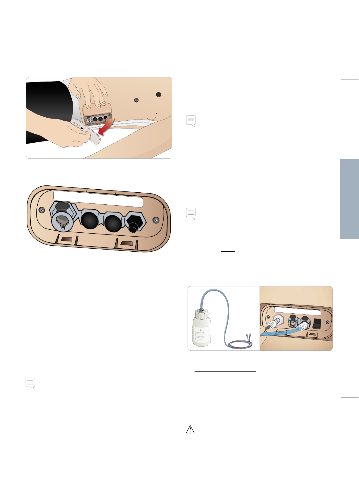
The Air/CO2 panel is located on the left side of the torso. To access
the panel, lift up the simulator skin flap and remove the protective
covering. Connect external Air/CO
Air/CO2 panel has 2 connection ports
.
2
Blood and Fluid System
The Patient Simulator has two internal reservoirs, one for blood and
one for fluids/secretions. SimMan 3G Trauma is also supplied with
two fill units - one Blood Fill Unit for blood and one Fluid Fill Unit for
fluids /secretions.
SimMan 3G Trauma Right Leg Fill Panel
The right leg fill panel is located at the top of the right leg near the
pelvis. The fill panel contains connectors for filling the blood and fluid
reservoirs.
Note: Make sure the Patient Simulator power is on.
Fill Internal Fluid Reservoir
1 Roll the right leg skin down to expose the fill panel.
2 Connect fluid fill unit tubes to the fluid and air connectors
in the right leg panel.
3 Push the fill button on the panel. The button will light up and
fluid will flow into the Patient Simulator.
4 When the flow stops, disconnect the fill unit.
5 Push the fill button on the panel. The light will go out.
Note: Disconnect tubes from the Patient Simulator before pushing
the fill button. Pushing the button before disconnecting the tubes
will initiate draining of the tank.
Cautions and WarningsFeaturesSetupMaintenanceSpare Parts Troubleshooting
Connecting External Air and CO2 Supply
An internal compressor is located in the right leg of the Patient
Simulator. It is recommended to use an external source of
compressed air whenever the Patient Simulator is stationary over
extended periods of use.
Connect CO
CO
with each ventilation. Exhaled CO2 can be detected with a real
2
capnographic device. The Patient Simulator will only exhale CO
when a capnograph is registered as being connected to the system.
1 Connect a suitable CO
compressor or regulator panel.
2 Connect a Laerdal double-lumen Air/CO
external compressor or regulator panel to the Air/CO
the panel.
For more information on external compressors and regulator
panels compatible with SimMan 3G Trauma, contact your local
Laerdal representative.
only if the Patient Simulator is required to exhale
2
source to a Laerdal external
2
tube from the
2
2
inlet on
2
Empty Internal Fluid Reservoir
1 Connect an empty fluid fill unit to fluid connector in
the right leg panel.
2 Fluid from the internal reservoir will drain into the bottle.
3 When the flow stops, disconnect the fluid connector.
Run Patient Simulator with External Fluid
1 Drain the internal reservoir. Follow instructions for “Empty
Internal Fluid Reservoir”.
2 After draining the internal reservoir, fill the fluid fill unit and
connect to the Patient Simulator.
3 Push the fill button on the panel. The button will light and fluid
will flow into the Patient Simulator.
4 Charge the system for 60 seconds before starting simulation.
Warning: Connecting a full fluid fill unit to a Patient Simulator with a
full internal reservoir will result in system overflow. Fluid will drain
out of the right leg. Repeatedly overflowing the system may
damage the product.
17
Page 18
S
i
m
M
a
n
B
l
o
o
d
F
i
l
l
U
n
i
t
S
i
m
M
a
n
B
l
o
o
d
F
i
l
l
U
n
i
t
S
i
m
M
a
n
B
l
o
o
d
F
i
l
l
U
n
i
t
Fluid
Inlet
Air Out
Blood
Inlet
Activate
Filling
S
i
m
M
a
n
B
l
o
o
d
F
i
l
l
U
n
i
t
S
i
m
M
a
n
B
l
o
o
d
F
i
l
l
U
n
i
t
S
i
m
M
a
n
B
l
o
o
d
F
i
l
l
U
n
i
t
Fluid
Inlet
Air Out
Blood
Inlet
Activate
Filling
SETUP
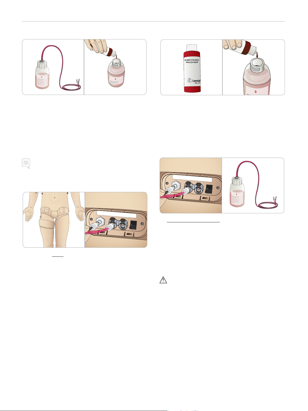
Fill Internal Blood Reservoir
1 Roll the right leg skin down to expose the fill panel.
2 Connect blood fill unit tubes to the blood and air connectors
in the right leg panel.
3 Push the fill button on the panel. The button will light up and
blood will flow into the Patient Simulator.
4 When the flow stops, disconnect the fill unit.
5 Push the fill button on the panel. The light will go out.
Note: Disconnect tubes from the Patient Simulator before pushing
the fill button. Pushing the button before disconnecting the tubes
will initiate draining of the tank.
Mixing of Blood and Fluid
To simulate clear fluids and secretions: Fill the Fluid Fill Unit with
de-ionized water (approx
To mix simulated blood: Fill the Blood Fill Unit with de-ionized water.
Add 5-10 drops of Laerdal Blood colored concentrate, mix and
tighten the cap.
3
/4 full) only and tighten the cap.
Run Patient Simulator with External Blood
Empty Internal Blood Reservoir
1 Connect an empty blood fill unit to blood connector
in the right leg panel.
2 Blood from the internal reservoir will drain into the bottle.
3 When the flow stops, disconnect the blood connector.
1 Drain the internal reservoir. Follow instructions for “Empty
Internal Blood Reservoir”.
2 After draining the internal reservoir, fill the blood fill unit and
connect to the Patient Simulator.
3 Push the fill button on the panel. The button will light and blood
will flow into the Patient Simulator.
4 Charge the system for 60 seconds before starting bleeding
simulation.
Warning: Connecting a full blood fill unit to a Patient Simulator with
a full internal reservoir will result in system overflow. Blood will
drain out of the right leg. Repeatedly overflowing the system may
damage the product.
18
Page 19
SETUP
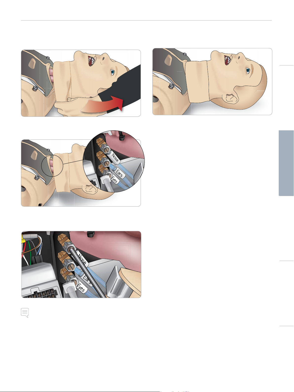
Adjusting Fluid Flow
1 Remove the neck skin.
Cautions and WarningsFeaturesSetupMaintenanceSpare Parts Troubleshooting
2 Locate the restrictor valves in the left and right clavicle area.
3 Activate secretion in the Circulation and Fluids Tab, then tighten
or loosen the actual valve as until desired flow rate is achieved.
4 Replace the neck skin.
Note: Do not unscrew completely. Please note that only slight
adjustment should be necessary.
19
Page 20
SETUP
Connecting Wounds Kit
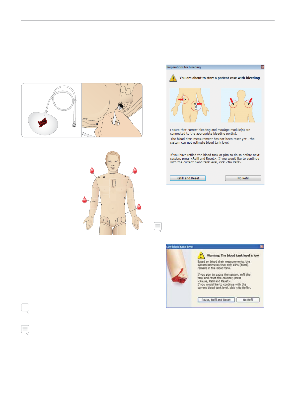
SimMan 3G Trauma comes with a wounds kit that includes 2 wounds
and double-sided tape to attach wounds to the Patient Simulator
skin.
Connect wounds to the bleeding ports on the Patient Simulator
torso to simulate a bleeding patient.
1 Select a wound from the wounds kit.
2 Connect the tube from the wound, to the nearest blood por t.
There are four blood ports with
twist and lock connectors, as
illustrated on the right.
− Ensure the area to which
the wound will be attached
is clean and dry.
− Apply adhesive tape to the
back side of the wound.
− Remove the protective
liner from the adhesive
tape on the wound and fix
it in the desired position on
the skin.
Simulate Severe Bleeding Using
LLEAP
Start a Patient Case with Bleeding in LLEAP
To extend bleeding patient simulations, a scale factor can be used.
Ensure, when the external Blood Fill Unit is empty; replace it with
another Blood Fill Unit filled with simulated blood. Repeat this
process for as many times as is necessary.
Note: If the external fill unit runs empty during a bleeding
scenarios, air will be introduced to the blood system, causing
inaccurate reading.
Removing Wounds
Flush all blood ports and tubes with distilled or de-ionized water
while the wounds are still attached. When the fluid runs clear,
disconnect the tube from the fluid outlet. After the wound is
removed, any tape residue can be cleaned from the Patient Simulator
skin with Laerdal Manikin Wipes.
Note: When removing wounds from the blood ports, cover the
Patient Simulator skin with a cloth to prevent staining.
Note: Trauma modules can be purchased separately to replace
default limbs to add realism to simulation.
20
Page 21
SETUP
Administering IV Fluids
To prevent clogging of the IV system, use only purified water to
simulate IV drugs with SimMan 3G Trauma.
Acceptable types of purified water:
– Distilled water OR
– De-ionized water.
Do not apply force when administering drugs to the IV Arm.
Priming the IV Arm System
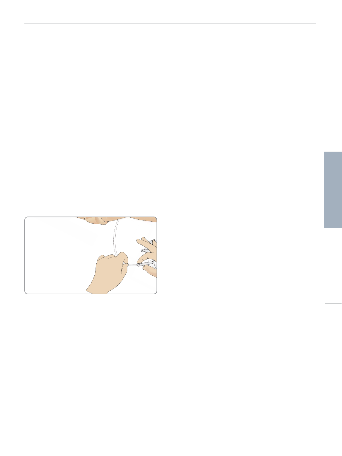
1 Use a syringe to inject blood concentrate and 500 cc of water
into an IV bag with tubing. This will serve as the blood source.
Attach the “blood source” bag with IV tubing to one of the
tubes exiting the manikin’s arm.
2 Attach an empty bag with IV tubing to the second tube exiting
the manikin’s arm. This bag will serve as the collection reservoir.
3 Control the flow of blood from the arm, via the clamp on the
collection reservoir tubing. Put the collection bag on the floor to
allow the now closed system to gravity feed.
4 Hang the “blood source” bag from an IV pole and open the
clamp to allow concentrate to flow through arm.
Cautions and WarningsFeaturesSetupMaintenanceSpare Parts Troubleshooting
Cleaning the IV Arm
Flush the IV Arm with warm water at the end of each day.
21
Page 22
SETUP
Connecting Defibrillation Adapter
Plates
Adding Defibrillation Adapter Plates
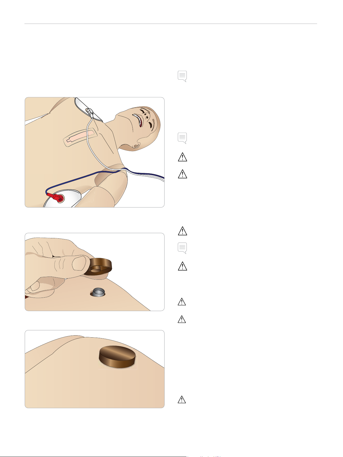
The Patient Simulator torso is fitted with two stud connectors for
defibrillator cables. Foam pads may be fitted around the defibrillator
studs during the session as illustrated below:
During Defibrillation
A conventional defibrillator may be used on SimMan 3G Trauma.
During live defibrillation, the defibrillator and Patient Simulator may
present a shock hazard. All standard safety precautions must be
taken when using the defibrillator on the Patient Simulator.
Note: Defibrillation must be performed on the defibrillator
connectors only.
To prevent overheating during defibrillation, do not exceed a
defibrillation sequence of 3 shocks in 45 seconds followed by
1 minute of CPR.
After 30 minutes there must be at least 15 minutes with no shocking
before starting a new sequence.
Note: Do not repeat this for more than a 4 hour period.
Warning: The Patient Simulator must not be in contact with
electrically conductive surfaces or objects during defibrillation.
Caution: In hot conditions, intensive defibrillation may cause
thermal shut down of the Patient Simulator.
Take care to avoid spillage when using the fluid systems while the
Patient Simulator is under defibrillation.
The defibrillator studs must be fitted in place before using a live
defibrillator with defibrillation paddles.
Press the adapter plates firmly into place.
To prevent Torso Skin electrode pitting, do not apply conductive gel
or conductive defibrillation pads intended for patient use.
Warning Do not defibrillate the Patient Simulator when it is OFF
or if it is not functioning normally.
Note: Do not press too hard over the defibrillation adapters as
this may cause arcing and pitting.
Warning: Do not defibrillate the Patient Simulator without the Torso
Skin.
A full service, including cleaning of the base board and its
compartments should be performed at regular intervals.
Warning: Do not defibrillate the Patient Simulator in a flammable
or oxygen enriched atmosphere.
Warning: The Patient Simulator torso must always be kept dry.
Allow the Patient Simulator to acclimate before defibrillating.
Sudden changes in temperature (moving the Patient Simulator
from a cold environment to a warm environment and vice versa)
may result in condensation collecting on the base board and pose
a shock hazard.
SimMan 3G Tr auma will automatically shut down whenever it detects
a significant increase in internal temperature. If automatic shut down
occurs, allow the Patient Simulator to cool down before resuming
the training session. Open the Torso Skin to speed up the cooling
process.
22
Warning: Do not use automated chest compression machines on
the Patient Simulator.
Page 23
SETUP
Connecting the Blood Pressure Cuff
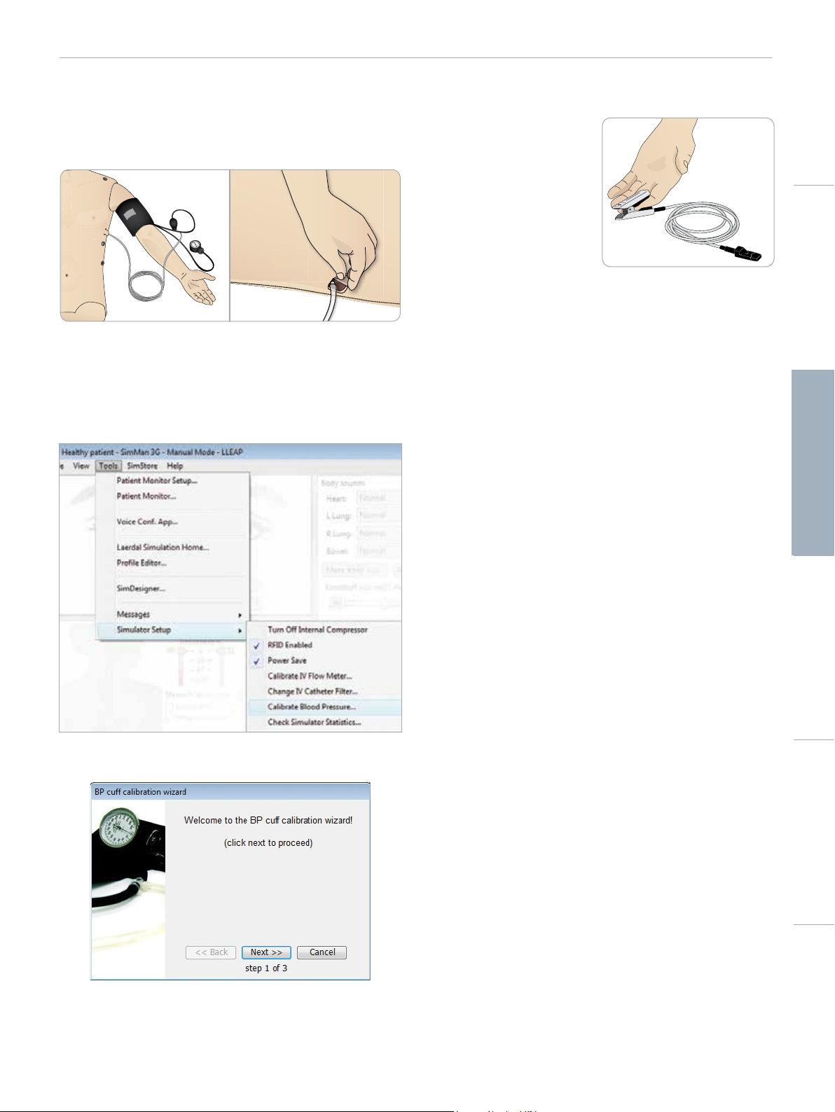
The Patient Simulator is delivered with a specially adjusted blood
pressure cuff. Connect the tube to the white BP connector at the
side of the Patient Simulator before use.
Calibrating the Blood Pressure Cuff
Using LLEAP
1 Select <Tools> <Maintenance> and choose <Calibrate BP...>
Connecting the SpO2 Probe
The SimMan 3G Trauma SpO2
probe is made up of a light
diode and light sensor. When
the beam between the diode
and sensor is broken, the
Patient Monitor Application
registers that the SpO
connected.
1 Connect the probe’s USB
plug to the Patient Monitor
PC.
2 The probe can be placed on any suitable area on the Patient
Simulator. Ensure that the probe is always firmly fixed in position.
probe is
2
Cautions and WarningsFeaturesSetupMaintenanceSpare Parts Troubleshooting
2 Follow the onscreen wizard instructions to perform the
calibration.
23
Page 24
SETUP
Changing Genitalia Modules
The SimMan 3G Trauma is shipped with a neutral genitalia pad as its
default. The pad can be exchanged for a male or female genitalia pad
with urine catheter to simulate urine flow and catheterization.
Note: The Patient Simulator legs do not need to be removed
before the genitalia pad can be replaced.
1 Remove the Patient Simulator’s genitalia pad by gripping the pad
at the top and pulling forward and down.
2 Disconnect any tubes or cables.
3 Connect the new Genitalia Module’s urine tube and the
catheterization sensor cable from inside the Patient Simulator
pelvis to the urine bladder module.
Changing the Upper Dentures
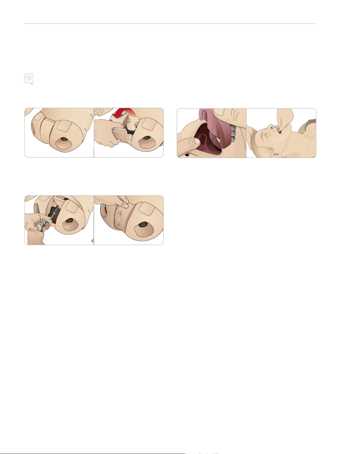
The Patient Simulator comes with a set of soft upper teeth as
default. The soft set may be replaced with a hard set of teeth.
1 Remove the teeth from the mouth.
2 Align the new set of teeth with the gums and push them back
until the teeth engage and lock onto the gums.
3 Ensure that the new set of teeth is properly aligned with the
gums before pushing them into place.
4 Place the new Genitalia Module back into the Patient Simulator’s
pelvis.
Inserting Urine Catheter
Always use a water based lubricant liberally when inserting a urine
catheter.
Use the following catheter sizes:
Female genitalia – Foley 14Ch and Lofric 16Ch
Male genitalia – Foley 16Ch and Lofric 16Ch
24
Page 25
LA PULSES BP
B
L
L
A
B
SETUP
Bleeding Modules
Introduction
The SimMan 3G Trauma Bleeding Module kit includes trauma
modules which can be fitted to SimMan 3G Trauma to simulate
bleeding patient cases. After the simulation is completed, leave the
trauma modules connected, and perform the cleaning instructions as
stated in Maintenance.
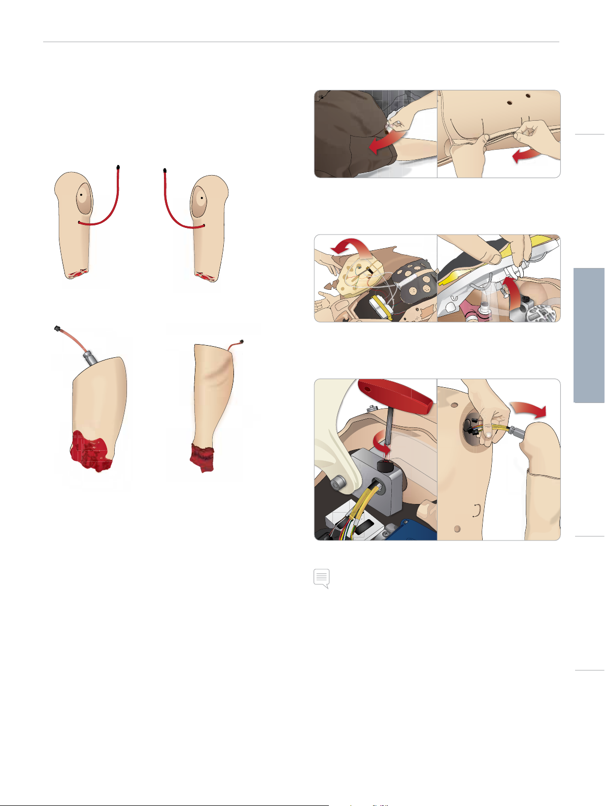
Removing SimMan 3G Trauma Left Arm
1 Unzip the clothing zippers on the right side. Remove the shirt.
Cautions and WarningsFeaturesSetupMaintenanceSpare Parts Troubleshooting
2 Unzip the zippers on the left side of the torso. Open the Torso
Skin to one side.
3 Open the Stomach Foam to one side.
4 Lift the hinged chest plate to access the arm bolt.
5 Unscrew the left Arm Screw with the allen key and disconnect
all Arm cables.
– Amputated Arm Left SimMan 3G Trauma
– Amputated Arm Right SimMan 3G Trauma
– Amputated Leg SimMan 3G Trauma
– Amputated Lower Calf Skin
6 Remove the arm with cables from the arm socket.
Note: Do not unscrew the Arm Screw fully.
25
Page 26
LA PULSES BP
BP
SETUP
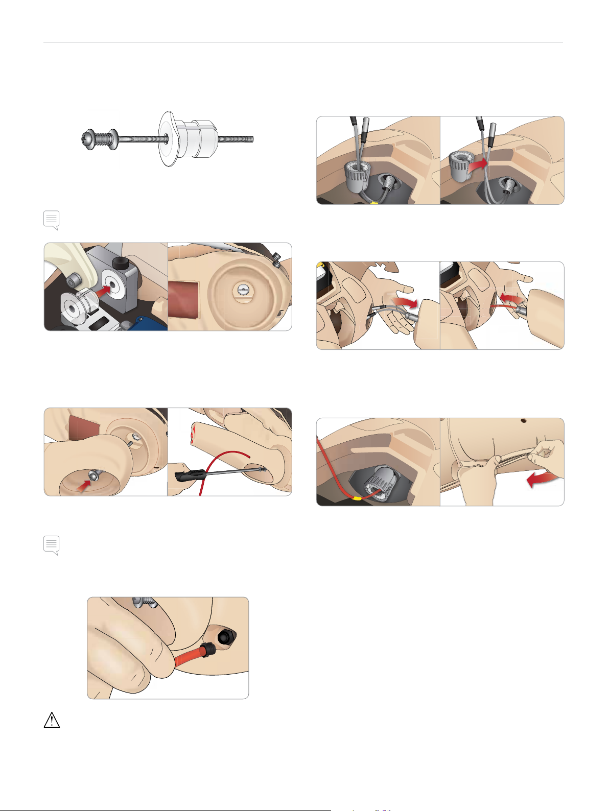
Attaching SimMan 3G Trauma Amputation
The Arm Adapter and Adapter Screw are designed to attach an
Amputation to the Patient Simulator.
1 Fit the Arm Adapter into the hole in the arm bracket from inside
of the torso.
Note: Ensure that the flat edge of the adapter is facing the chest
hinge.
2 The Adapter is now in place and the Trauma Arm can now be
connected with the Adapter Screw.
3 Thread the Adapter Screw through the Amputation Arm and
align the screw with the hole in the Arm Adapter.
Replacing SimMan 3G Trauma Left Leg with
Trauma Leg
1 Remove the SimMan 3G Trauma default leg. Open Torso Skin
and Stomach Foam as shown in Maintenance.
2 Unscrew hip joint connector. Remove the leg cables/tubes from
the connector.
3 Carefully remove the left leg with cables and tubes.
4 Insert the Amputation or Gunshot Leg with blood tube into the
leg socket.
5 Insert the blood tube into the side slot of the connector. Screw
the connector in place with one hand.
4 Secure the Adapter with one hand from inside the torso. Screw
the Adapter Screw using the Phillips screwdriver.
Note: Tighten screw as desired to simulate more or less range of
motion in the arm.
5 Connect the red tube from the Amputation Arm to the nearest
blood port on the torso.
Caution: Do not over rotate arm. Over rotating the arm may cause
the red vinyl tubing to disconnect.
6 Connect the leg tube to the corresponding tube, as labelled
inside the torso.
7 Close the Stomach Foam and zip the Torso Skin back into place.
26
Page 27
SETUP
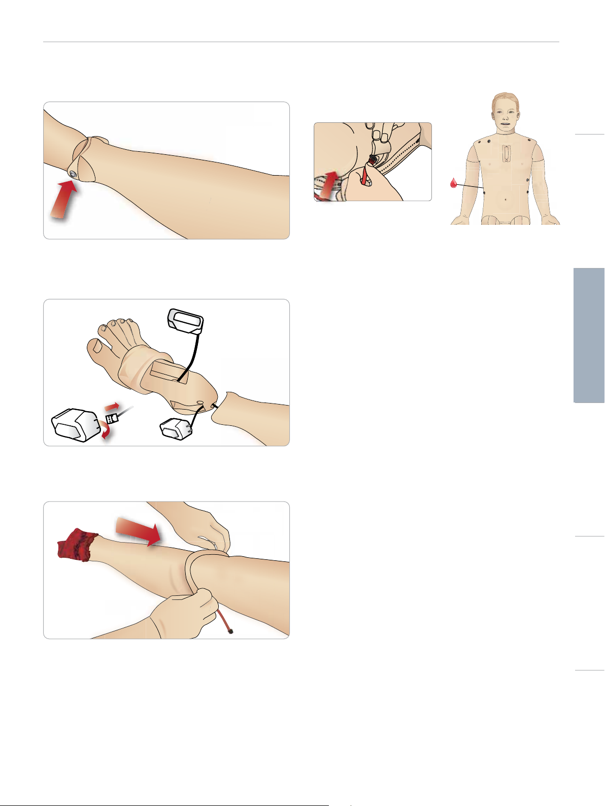
Installing the Amputated Lower Calf Skin
1 Access the ankle bolts by folding the skin up. Remove the ankle
bolts using two Phillips head screw drivers.
2 Carefully fold down the skin of the foot to expose the two pulse
units. Disconnect both units and route the wiring out of the
foot. Roll the wires together and store in the bottom of the
ankle.
4 Connect the blood tubing to the blood port located on the
simulator’s right side.
Cautions and WarningsFeaturesSetupMaintenanceSpare Parts Troubleshooting
3 Apply a liberal amount of baby powder inside of the Amputated
Lower Calf Skin and lower leg. While matching the contours of
the skin to the calf, pull the skin up the simulator’s lower leg untill
it fits tightly.
27
Page 28
3.
SETUP
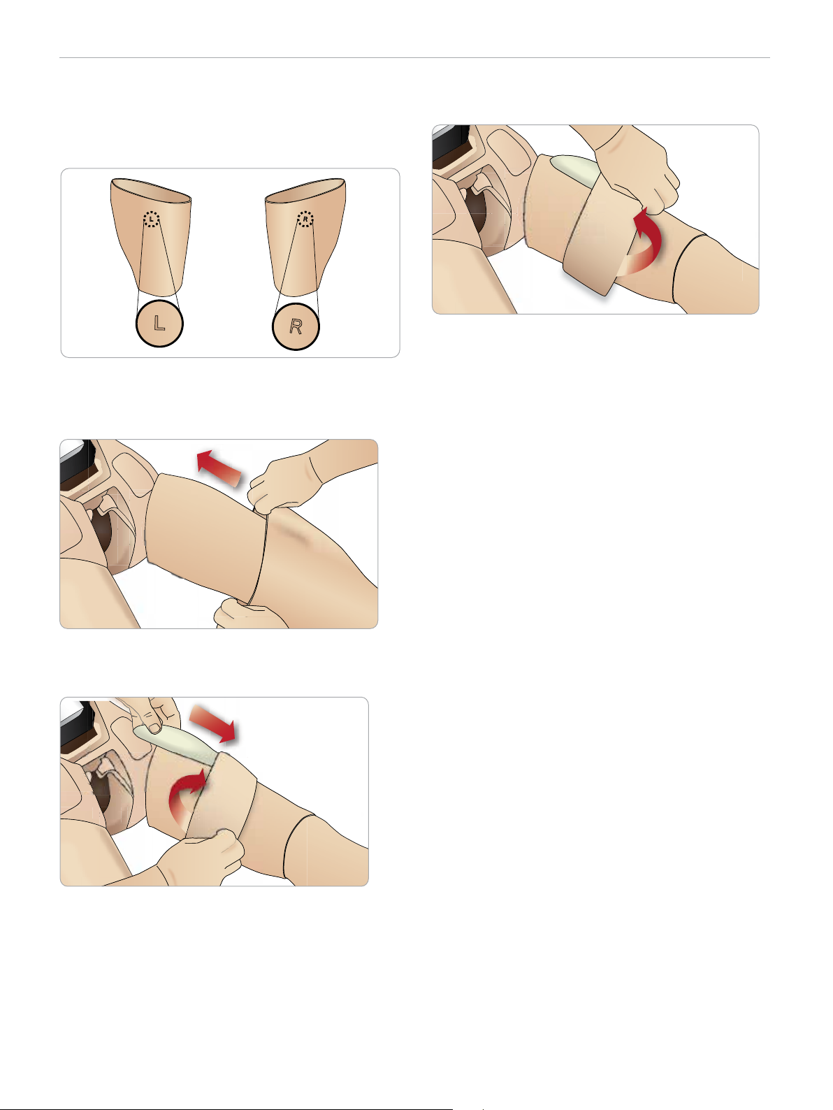
Installing Right and Left IM Thigh Skins
1 The dorsal side of each IM Thigh Skin is marked by either an “L”
or “R”. This marking should be aligned with the corresponding
“L” or “R” on the upper dorsal thigh of the simulator’s.
2 Apply a liberal amount of baby powder to the inside of the skin
and leg and pull the skin all the way up until it is even with the
top of the leg skin.
4 The Foam IM Pad should sit 1” (2.5 cm) from the top edge of
the leg. Replace the skin.
3 Fold the skin half way down and carefully insert the Foam IM
Pad underneath the skin. The Foam IM Pad could tear if
mishandled.
28
Page 29
SETUP
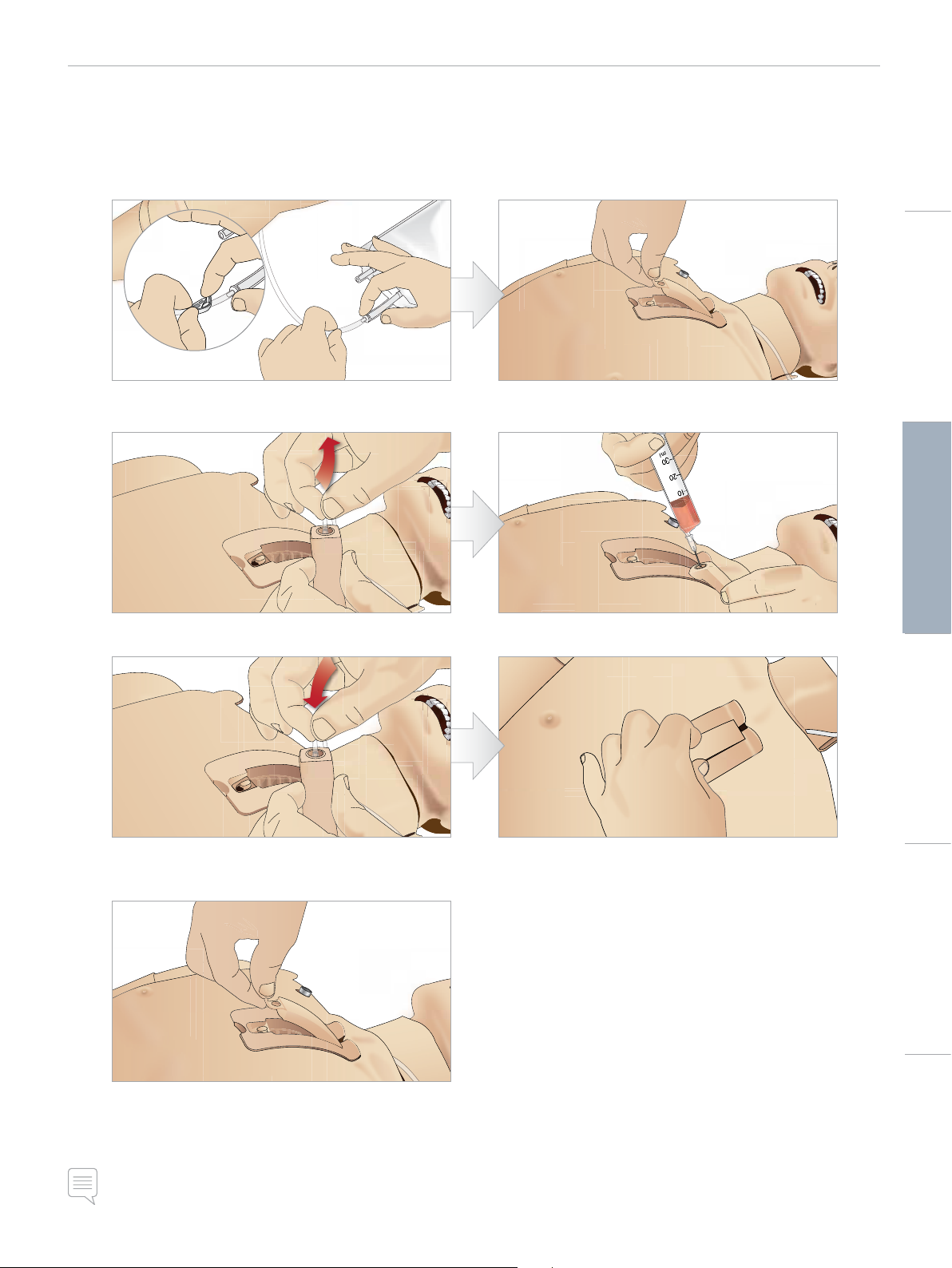
Replacing and Filling IO Units with Blood
The IO Pads supplied with SimMan 3G Trauma are disposable parts meant for single use.
Sternal IO
1 Attach the Sternal IO bag to the Sternal tube and close
off the pinch clamp.
3 Remove the Sternal tube from the sternal pad. 4 Fill the sternal IO pad with 7ml of blood. Ensure the pad
2 Remove the Sternal IO pad from the manikin chest.
is completely filled.
Cautions and WarningsFeaturesSetupMaintenanceSpare Parts Troubleshooting
5 Reattach the Sternal tube to the Sternal IO pad. 6 Place the Sternal IO unit in the Sternal Chassis. Slide
the unit down and towards the neck, until it fits securely
under the top edge of the chassis.
7 Reattach the sternal IO pad
The sternal IO is now ready for simulation.
Note: If bits of plastic from the module get stuck in the needle, flush the needle with fluid to dislodge the obstruction.
29
Page 30
SETUP
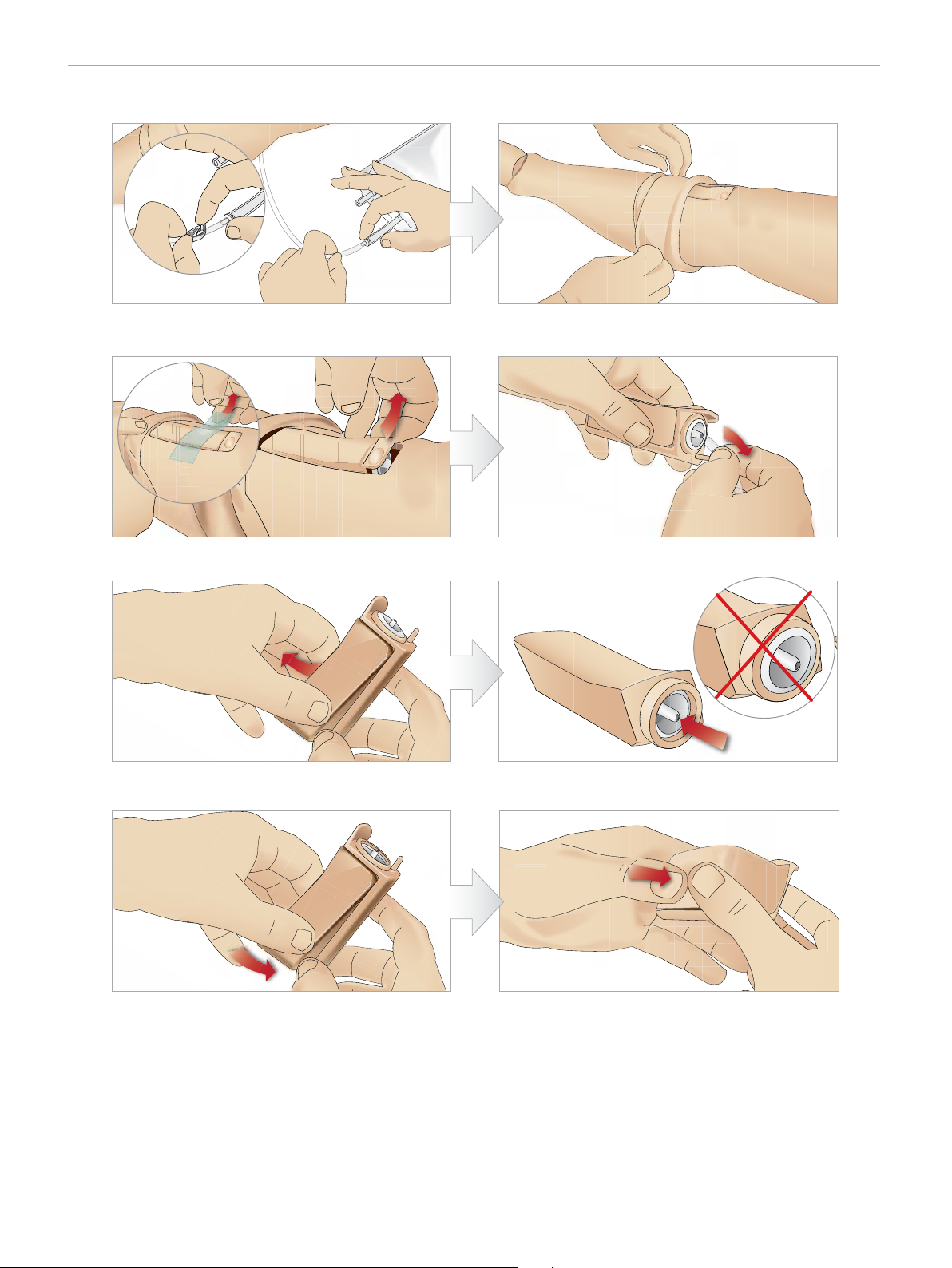
Tibial IO
1 Attach the Tibial IO bag to the Tibial tube and close off
the pinch clamp.
3 Remove the IO tape. Then remove the Tibial IO Unit
from the leg.
5 Remove the Tibial IO Pad from the Tibial IO chassis. 6 Before replacing the new Tibial IO, ensure that the nipple
2 Roll the leg band, to expose the Tibial IO Unit.
4 Remove the tube from the Tibial IO Unit.
is retracted in the Tibial IO Pad.
7 Fit the new Tibial IO Pad into the chassis. 8 Secure the Tibial IO Pad in place by pressing the rear of
the pad with thumbs until the nipple moves forward and
locks the unit in place.
30
Page 31
SETUP
Cautions and WarningsFeaturesSetupMaintenanceSpare Parts Troubleshooting
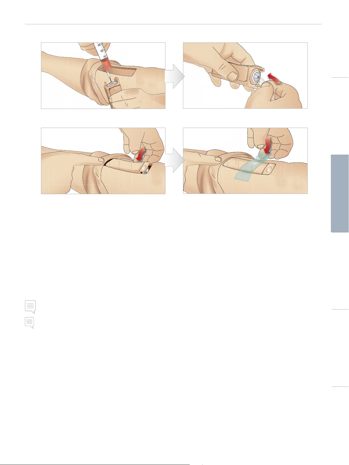
1 Fill the Tibial IO Unit with 30 - 35ml of blood, ensure
the Tibial Pad is completely full.
11 Replace the Tibial IO Pad and chassis, into the leg cavity. 12 Affix the tape to keep the Unit in place.
Roll the leg skin up over the Tibial Unit. The Tibial IO is now ready
for simulation.
The following devices have been tested and are approved for use
with the simulator:
– BIG Automatic Intraosseous Device
– EZ-IO-G3, 15G x 1”, 1.8mm x 25mm
– Jamshidi ® Illinois Bone Marrow Aspiration/Intraosseous Infusion
Needle. 18 Ga. 9/16” (14mm)-1 ½” (38mm).
– F.A.S.T 1 ™
10 Connect the Tibial tube to the Tibial IO Unit.
Note: In some cases you will not get any blood backflow when
using the F.A.S.T 1 ™
Note: in some cases, there will be no blood backflow when using
the BIG Automatic Intraosseous Device
31
Page 32
SETUP
Transporting SimMan 3G Trauma
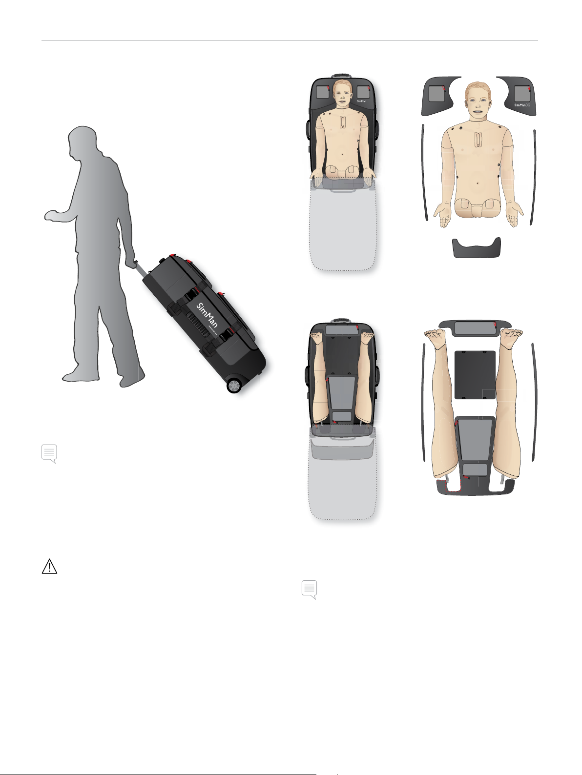
The SimMan 3G Trauma Simulation System consists of two cases for
easy transport and storage; one for the Patient Simulator legs and
one for the torso.
Torso Case with foam inserts
Leg Case with foam inserts
Each case has an extendable handle and may be stacked onto the
integrated wheel frame for increased mobility.
Note: The SimMan 3G Trauma System exceeds the weight
allowance on most commercial airlines. Some parts may have
to be transported separately. For more information on weight
restrictions contact the relevant airline.
Disassemble the legs from the torso and pack them into their
respective cases before transportation or storage.
For instructions on how to disassemble the legs, see: Attaching the
Left and Attaching the Right Leg.
Warning: The suitcases are heavy. Always ensure that they are
firmly secured during transportation and storage so as not to cause
personal injury or damage to the product.
Please be aware that both cases appear identical. Each case contains
compartments for all accessories.
For more information on SimMan 3G Trauma accessories, see Spare
Parts and Accessories section.
Note: Do not store or ship the simulator with Isopropanol or liquid
in any of the fluid or liquid systems.
Unpacking the Patient Simulator
Unpack the Patient Simulator torso and legs following the
instructions in reverse order of packing.
32
Page 33

MAINTENANCE
Daily Maintenance
The following preventive measures are required to ensure longevity
of the Patient Simulator.
IV Arm
After each session where the IV Arm has been used, flush the IV
Arm with warm water.
Fluid System
After each session where the fluid system has been used, drain the
internal fluid reservoir. See Empty Internal Fluid Reservoir section.
Blood System
When the day’s sessions are done, flush the blood system with
distilled or de-ionized water, with the wounds connected. This is to
remove remains of Laerdal blood in the blood system, and prevent
clogging of valves and tubing.
Power off the Patient Simulator and PCs
Charge batteries if necessary.
Clean the Skin
Wipe the skin with a moist cloth to remove stains. Remove wet
clothes or linens. Glue residue from the wound module tapes may
be removed with Manikin Wipes.
Before Storage or Shipping
IV Arm
Flush the IV Arm with warm water and let fully dry before storing.
Cautions and WarningsFeaturesSetupMaintenanceSpare Parts Troubleshooting
Fluid and Blood System
Before storage, the simulator’s Fluid and Blood Systems should be
flushed with Isopropanol 60%-70%, and then left to dry to remove
any Isopropanol residue from the system.
See Regular Cleaning of Fluid and Blood System section
Note: Do not store or ship the simulator with Isopropanol or liquid
in any of the fluid/liquid systems.
Detach the Patient Simulator’s legs from the torso and pack into the
transport cases as illustrated in Transporting SimMan 3G Trauma
Regular Cleaning of Fluid and
Blood System
Regular cleaning of the Fluid and Blood System is recommended as
part of proper care of the product. Once or twice a month, the Fluid
and Blood System should be cleaned thoroughly.
General Clean-up
− Return Patient Simulator and PCs to original state
Single Use Modules
Based on the use of the Patient Simulator, replace modules that are
spent or damaged:
− Cricothyrotomy: Crico-tape and neck-skin
− Chest drain module pleura
Multiple-use Modules
− Fluid filter
− IV catheter filter
− IV catheter
− Pneumothorax Bladders
− IO-modules (tibia and sternum)
− Chest Rise Bladders
− Lung Bladders
− Patient Simulator skins (body, legs, arms)
Note: For additional maintenance information related to the Fluid
and Blood System, see Daily Maintenance section.
Note: During the cleaning procedure – Tank empty warning - may
occur in LLEAP Software. This message can be disregarded during
the cleaning procedure.
Fluid System
To clean the Fluid System follow these steps:
Empty the system of water
1 Ensure that the simulator’s power is ON.
2 2 Ensure that the simulator’s internal fluid reservoir is drained.
See Empty Internal Fluid Reservoir section.
3 Press the fill button located on the fill panel. The LED indicator
on the fill button will light up.
4 Connect an empty fill bottle to the fluid and air connector in the
fill panel, and the filling of air into the internal reser voir will start.
5 We recommend covering the simulator’s head with a towel, as
pumping air through the system might cause some squirting.
6 With the fill button activated; from the LLEAP software open the
Circulation and fluids tab and check the boxes for Sweat, Ears,
Eyes, Nose, Mouth and Urine (polyuria).
7 Wait until there are no more fluids emitted from the simulator,
then uncheck all boxes.
8 Disconnect the empty fill bottle.
33
Page 34

MAINTENANCE
Flush the system with isopropanol
9 Connect a fill bottle with isopropanol to the fluid and air
connector in the fill panel, and the filling of isopropanol into the
internal reservoir will start.
10 From LLEAP, check the boxes for Sweat, Ears, Eyes, Nose, Mouth
and Urine (polyuria).
11 Wait until isopropanol is emitted from all the fluid outlets.
12 When the system is flushed with isopropanol, press the fill
button again to deactivate the filling of isopropanol to the
reservoir. The LED indicator on the fill button will now be off.
13 Leave the isopropanol fill bottle connected for approx. 30
seconds to let the internal reservoir drain completely.
14 In LLEAP uncheck all of the secretion boxes and disconnect the
fill bottle.
Empty the system of isopropanol
15 Connect an empty fill bottle to the fill panel and repeat steps 3-7
above to remove the Isopropanol from the fluid system, using air.
16 Press the fill button once again so that filling is disabled (LED
indicator should be off) and disconnect the empty fill bottle.
Note: Never store the simulator with Isopropanol or liquid in the
fluid system.
Blood System
To clean the Blood System follow these steps:
Flush the system with Isopropanol
9 Connect a fill bottle with isopropanol to the blood and air
connector in fill panel and the filling of isopropanol into the
internal reservoir will start.
10 Check the boxes for Upper and Lower port In LLEAP (making
sure Venous bleeding and maximum blood rates are still
selected).
11 Allow the blood system to flush until clear fluid runs out of all
outlets.
12 When finished, press fill button to deactivate the filling
procedure. LED-indicator on fill button will be off.
13 Leave the isopropanol fill bottle connected for approx. 30
seconds to let the internal reservoir drain completely.
14 In LLEAP, uncheck all boxes and move the sliders all the way to
the left. Disconnect the fill bottle.
Empty the system of isopropanol
15 Connect an empty fill bottle to the fill panel and repeat the steps
4-6 above to flush the Isopropanol out of the blood system,
using air.
16 Wait until there are no more fluids emitted from the simulator,
then press the fill button once again so that filling is disabled
(LED indicator should be off).
17 In the LLEAP Software uncheck all boxes and move the sliders
all the way to the left. Disconnect the fill bottle and Wounds.
Note: Never store the simulator with Isopropanol or liquid in the
fluid system.
Empty the system of water
1 Ensure that the simulator’s power is ON.
2 Ensure that the simulator’s internal blood reservoir is drained.
See Empty Internal Blood Reservoir section.
3 Connect Laerdal Wounds to blood outlets. See Connecting
Wound kits.
4 Press the fill button located on the fill panel. The LED indicator
on the fill button will light up.
5 Connect an empty fill bottle to the blood and air connector in
the fill panel, and the filling of air into the internal reser voir will
start.
6 With the fill button activated; open the Circulation and fluids tab
in LLEAP and check the boxes for Upper and Lower port, then
select Venous from the adjacent drop-down menus. Move the
sliders to the right to get maximum bleeding rates.
7 Wait until there is no more blood emitted from the simulator,
then uncheck all boxes.
8 Disconnect the empty fill bottle.
34
Page 35
MAINTENANCE
Installing and Upgrading LLEAP
The Laerdal simulator Software comes preinstalled. When updating
LLEAP, check also if updates for Patient Monitor, SimDesigner and
SessionViewer/SimView are available. All available Software must be
updated at the same occasion. Install or update the Software in the
following order:
1 Update the Software on the instructor PC. See Instructor PC
and Patient Monitor PC section.
2 Update the Software on the Patient Monitor PC. See Instructor
PC and Patient Monitor PC section.
3 Update the Software on the Patient Simulator. See Simulator
Firmware & Network Wizard section.
Instructor PC and Patient Monitor PC
1 Power on your simulator computers and ensure no simulator
applications are running.
2 Visit www.laerdal.com/downloads to download the latest version
of LLEAP and/or Laerdal Patient Monitor installers. Execute
the file after it has been downloaded. Follow the on-screen
instructions to complete the installation.
Note: It is recommended that simulator software on all your
computers are updated at the same time to ensure continued
compatibility after the update.
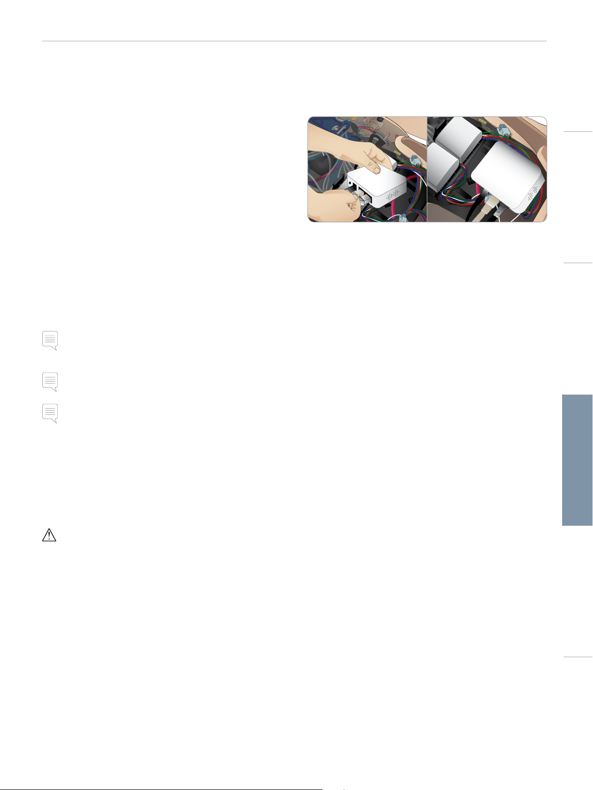
Removing/Changing Router
The router may be changed or removed. Turn off the Patient
Simulator before doing so.
Cautions and WarningsFeaturesSetupMaintenanceSpare Parts Troubleshooting
Open the pelvis and locate the router. Remove the two Ethernet
cables and black power cable.
If you would like to operate the Patient Simulator without a router,
then attach a through-adapter between the two Ethernet cables.
If you would like to install a new router, attach the power cable to
the DC plug and the Ethernet cables back into the router again.
Note: The LLEAP installer also includes Session Viewer and
SimDesigner.
The LLEAP and Patient Monitor applications will offer to download
and install new versions if started while connected to Internet
Simulator Firmware & Network Wizard
The Patient Simulator software update is handled by the Simulator
Firmware & Network Wizard application. To update the Patient
Simulator software, follow the instructions in Simulator Firmware &
Network Wizard Help.
Caution: Do not switch OFF the Patient Simulator while updating
the Patient Simulator software.
35
Page 36
MAINTENANCE
Opening the Torso
Open the Patient Simulator torso for the following procedures:
Attaching or replacing limbs
− Attaching or dismantling the Patient Simulator legs and arms.
− Exchanging default arms for IV or trauma arms.
Maintenance Tasks
− Changing the Patient Simulator batteries.
− Replacing the Pneumothorax Bladders, Chest Rise Bladders, Lung
Bladders, IO Modules and Chest Drain Modules.
− Replacing the Torso Skin.
− Performing a general inspection.
− Removing WLAN adapter.
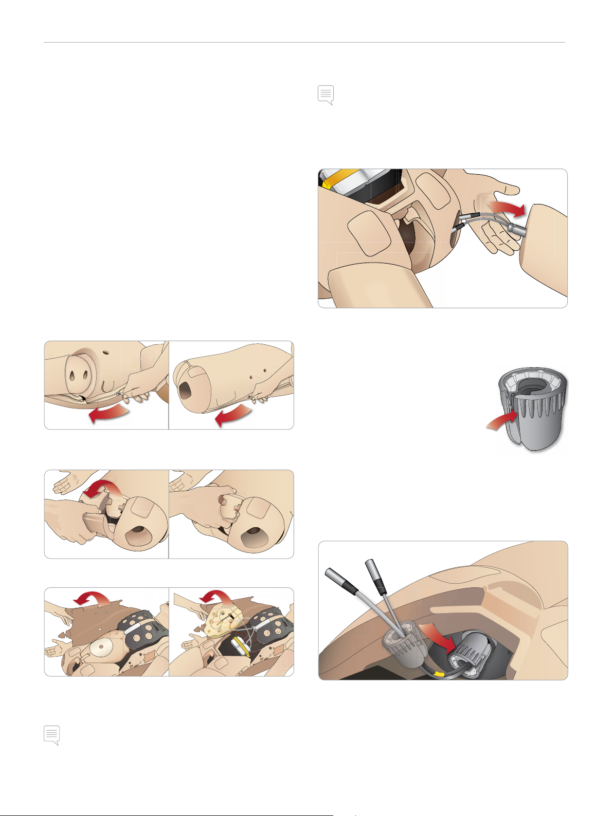
To open the Torso Skin
1 Unzip the zippers on the Patient Simulator’s left shoulder and
torso.
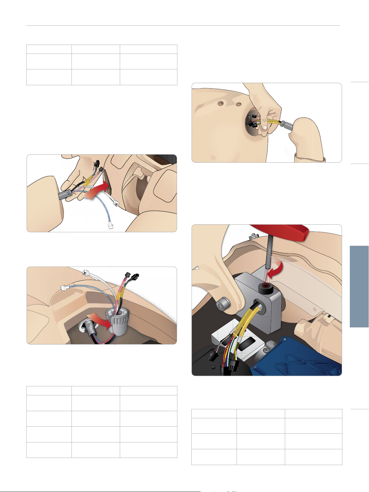
Attaching the Left Leg
Note: Assemble the Patient Simulator on a large flat surface. Attach
the Left Leg before the Right Leg.
Open the torso to access the hip joint connectors. To open the
torso follow steps 1 – 4, Opening the Torso.
1 Align the left leg bolt and cables with the pelvis socket.
2 Feed the leg bolt and cables through the socket and into the
torso. Do not pull the leg by the cables and/or tubes.
3 Carefully push the leg in towards the pelvis to form a snug fit.
Hip joint connector with side slot for
inserting cables and tubes (shown right)
2 Remove the Genitalia Module and release the skin flap from the
pelvis.
3 Fold the Torso Skin over to one side.
4 Open the Stomach Foam to one side, taking care not to tug on
the connecting tubes and cables.
4 Position the connector rounded end
facing downward. Place the leg cables
and tubes into the side slot of the
connector.
5 Slide the connector downwards along
the tubes and cables and onto the leg bolt. Ensure that the nut
and bolt are aligned, and that all cables and tubes are secured
within the connector.
6 Screw the connector onto the leg bolt. Avoid twisting the tubes
and cables. Tighten the connector so that the leg is able to rotate
freely around the hip joint connector.
7 Connect the corresponding leg tubes and cables as shown in the
following table:
Note: DO NOT disconnect the tubes and cables connecting the
Stomach Foam to the Patient Simulator.
5 Replace the Stomach Foam and close the Torso Skin, perform
steps 1- 4 in reverse.
36
Page 37
LA PULSES BP
LA CONV
L
L
A
B
MAINTENANCE
Left Leg to Pelvis – Cable and Tube Descriptions
Name/Label Tube/Cable Color Connector Description
Left Pedal Grey cable black with silver
coloured connector
Popliteal Grey cable black with silver
coloured connector
Attaching the Right Leg
Please take the same precautions as when attaching the Left Leg.
1 Align the Right Leg bolt and cables with the pelvis socket. Feed
the leg bolt and cabling through the pelvis socket.
Attaching the Left Arm
Open the torso as described in steps 1 - 4, Opening the Torso.
Follow the procedures listed below in reverse to detach the arms.
1 Align the left arm axle with the shoulder socket.
2 Ensure that the shoulder screw is loose enough to allow the arm
axle to slide easily into place.
3 Feed the cables from the arm axle through the shoulder socket.
4 Carefully push the arm axle into the shoulder bracket, so that
the axle is flush with the inside of the bracket.
5 Tighten the shoulder screw with the Allen wrench.
Cautions and WarningsFeaturesSetupMaintenanceSpare Parts Troubleshooting
2 Carefully push the leg in towards the pelvis to form a snug fit.
3 Secure the cables and tubes in the connector. Screw the
connector in place on the leg bolt.
4 Connect the corresponding tubes and cables as shown in the
table below:
Right Leg to Pelvis – Cable and Tube Descriptions
Name/Label Tube/Cable Color Connector Description
Blood Right Leg Transparent, red
tube
Right Leg Black harness cable Black rectangular
Fluid from leg Tube, blue White twist and lock
Air from leg Colourless
transparent tube
Black twist and lock
connector
connector, 4 lead
connector
White twist and lock
connector
6 Connect the arm cables to the corresponding connection points
in the torso.
Left Arm to Torso – Cable and Tube Descriptions
Name/Label Tube/Cable Color Connector Description
LA Pulses Grey cable Black rectangular
connector, 6 lead
BP Grey cable Black rectangular
connector, 2 lead
LA Conv Black harness cable Black rectangular
connector, 8 lead
37
Page 38
LA PULSES BP
BP
MAINTENANCE
Attaching the Right Arm
Open the torso as described in steps 1 - 4, Opening the Torso.
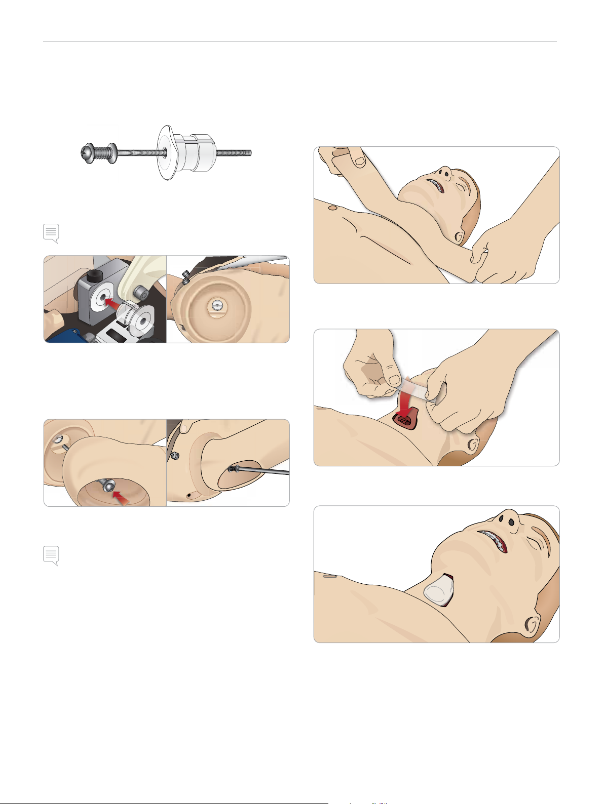
The Arm Adapter and Adapter Screw are designed to attach the
Right Arm to the Patient Simulator.
1 Fit the Arm Adapter into the hole in the arm bracket from inside
of the torso.
Note: Ensure that the flat edge of the adapter is facing the chest
hinge.
Replacing Crico Tape/Neck Skin
After creating an emergency airway through the cricothyroid
membrane, replace the perforated membrane before starting a new
simulation session.
1 Remove the Neck Skin (velcro fasteners behind the neck).
2 Remove the old strip of Crico Tape.
3 Replace with a new Crico Tape.
2 The Adapter is now in place and the Right Arm can now be
connected with the Adapter Screw.
3 Thread the Adapter Screw through the Right Arm and align the
screw with the hole in the Arm Adapter.
4 Secure the Adapter with one hand from inside the torso. Screw
the Adapter Screw using the Phillips screwdriver.
Note: Tighten screw as desired to simulate more or less range of
motion in the arm.
Follow the procedures listed below in reverse to detach the arms.
4 Ensure Crico Tape completely covers and seals the opening to
prevent leakage while ventilating the Patient Simulator.
38
Page 39
MAINTENANCE
Replacing Chest Drain Pleura
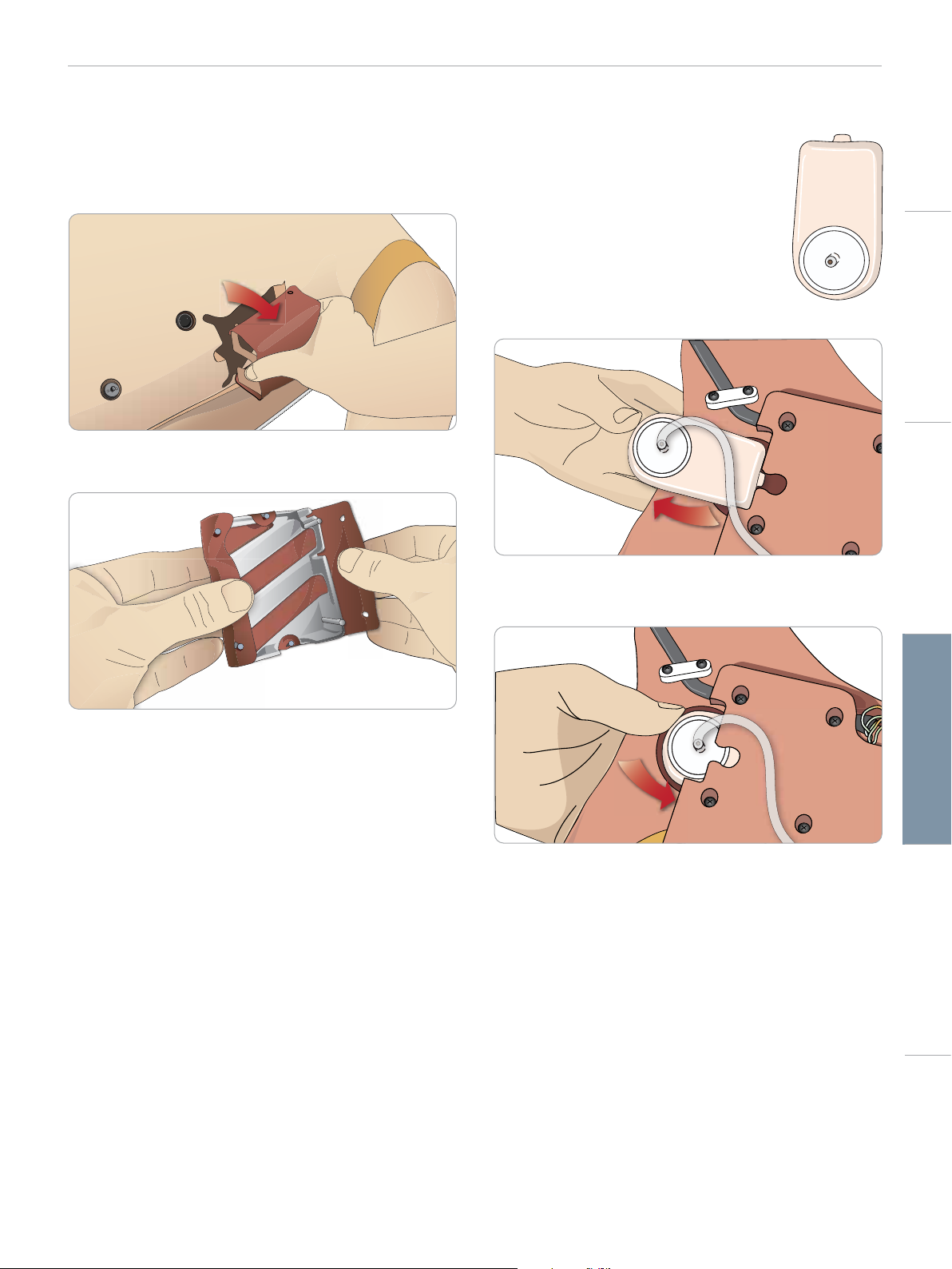
The Chest Drain Module’s Pleura Skin should be replaced after
each use.
1 Open the Torso Skin and remove the module from the chest.
2 Remove the old Pleura skin, and replace with a new skin and
replace the module.
Replacing Pneumothorax Bladders
After multiple pneumothorax decompressions,
the bladders may need replacement:
Cautions and WarningsFeaturesSetupMaintenanceSpare Parts Troubleshooting
1 Open the Torso Skin to expose the chest
plate. Lift the Chest Plate to reveal the
Pneumothorax Bladders located in slots in the
side of the Chest Plate assembly.
2 Slide out the used Pneumothorax Bladder.
3 Disconnect the tube and discard the old
bladder.
4 Insert the new bladder into the slot.
5 Reconnect the tube to the new bladder.
39
Page 40
MAINTENANCE
Replacing Chest Rise Bladder
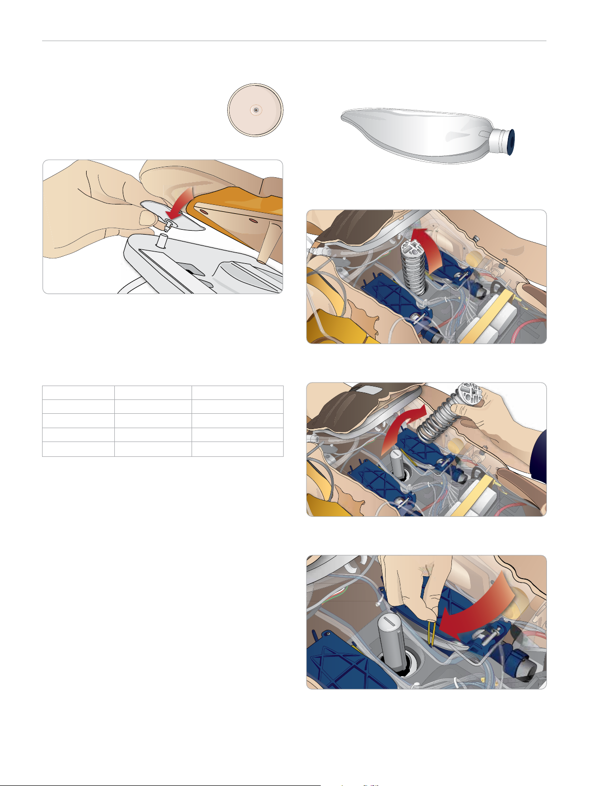
If the Chest Rise Bladders leak or are damaged:
1 Open the Torso Skin to expose the Chest
Plate. There is one bladder on each side of the
Chest Plate assembly.
2 Disconnect the tube from the bladder.
3 Discard the used bladder.
4 Insert new bladder.
5 Reconnect the tube to the new bladder.
Replacing Lung Bladders
If leaking occurs, the Lung Bladders (in the chest cavity) should be
replaced.
1 Open the Torso Skin and put the Stomach Foam to the side.
2 Open the hinged Chest Plate upwards, to access the lungs.
Left Leg to Pelvis – Tube Descriptions
Name/Label Tube Color Connector Description
Pneum L Silicon Barb connector
Pneum R Silicon Barb connector
Chest L Silicon Barb connector
Chest R Silicon Barb connector
3 Remove the chest compression spring for easier access to the
lungs.
4 Unhook the yellow lung compliance bands from each side of the
lung assembly.
5 Open the hinged lung plate.
6 Pull the old lung out from its socket.
40
Page 41
B
l
o
o
d
R
i
g
h
t
L
e
g
MAINTENANCE
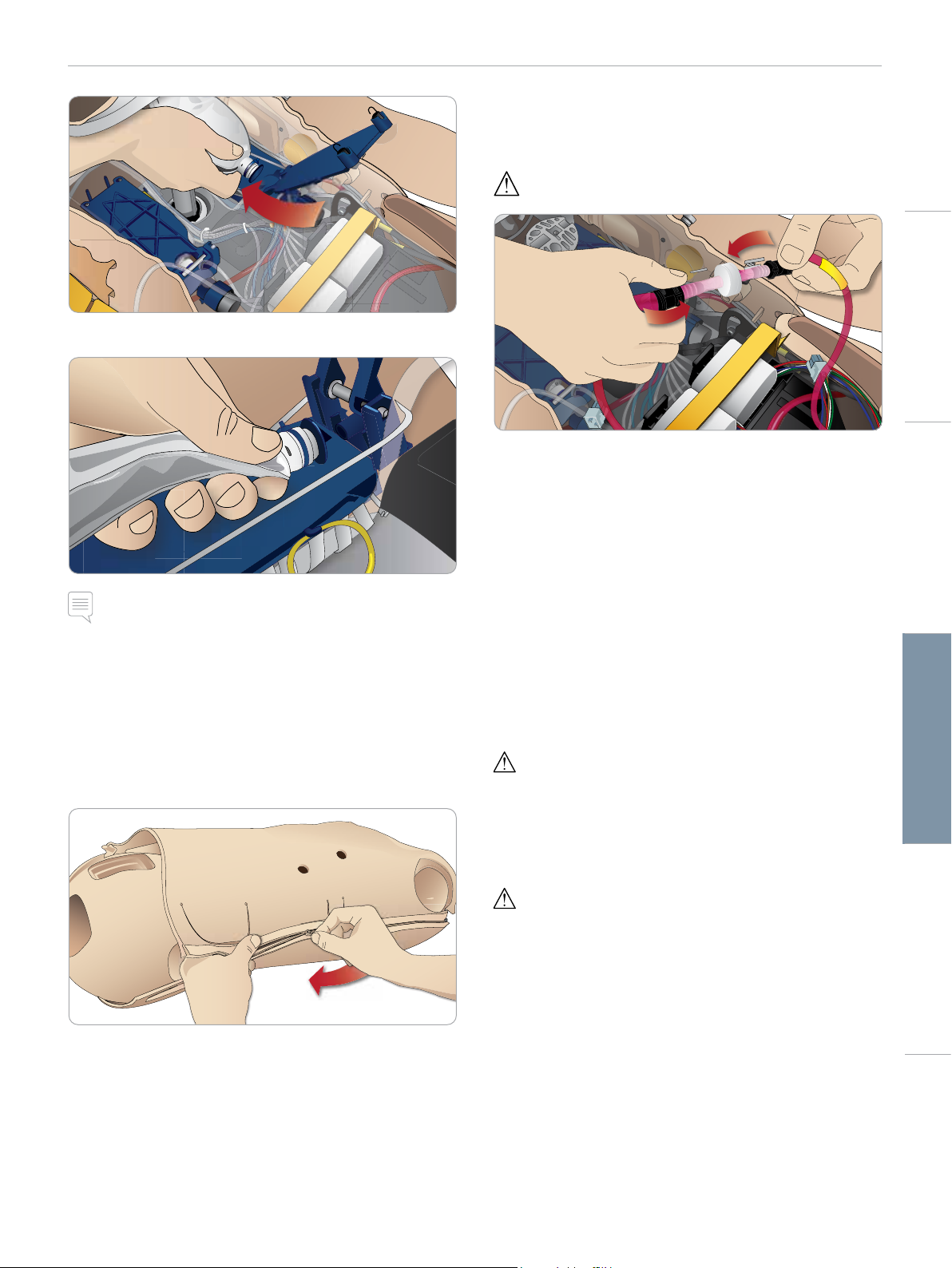
Replacing Blood System Filter
If reduced blood flow is experienced, the filter may be clogged and
needs replacement.
Never run the Patient Simulator without a filter.
7 Reverse this process to insert a new lung.
1 Turn off the Patient Simulator.
2 Remove genitalia with the catheterization assembly for easy
access.
3 Disconnect the filter from the right leg and pelvis blood tubes
and remove it.
4 Connect a new filter by reversing the steps above.
Note: Ensure that the compliance bands intersect between the
two folds of the lung.
Cautions and WarningsFeaturesSetupMaintenanceSpare Parts Troubleshooting
Replacing Simulator Skins
The simulator skins may need to be replaced if they become torn,
perforated, or stained.
1 Unzip and unroll the skin.
2 Applying powder to the inside of arm, torso and leg skins will
help reduce friction and make replacing the skins easier.
To prevent the zippers from separating from the skin, make sure
to properly position the skin halves and hold them together while
zipping them closed.
Servicing the Patient Simulator
A full service, including cleaning of the base board, should be
performed at regular intervals.
Caution: All ser vicing must be performed by qualified service
personnel.
Always perform a service:
− If liquids have been spilled in the Patient Simulator
− After use in dusty environments.
Caution: Do not use cables or connectors showing visible damage.
41
Page 42

TROUBLESHOOTING
Troubleshooting
System Setup
Problem
– Lost data or total system failure (General System failure).
Solution
– Should system shut down or all data is lost or corrupted; please
contact your local Laerdal Service Center.
Stability And Connection In Access Point Mode
(Ap) (Patient Simulator Created Network)
Problem
– Connection between LLEAP and/or Patient Monitor and Patient
Simulator is lost.
Causes
– Other software on PCs may interfere with LLEAP or Patient
Monitor.
– Multiple network connections may interfere with transmissions
between our software and Patient Simulator.
Possible Solutions
– Remove unnecessary software on PCs.
– Disable other networks.
Stability and Connection in Client Mode
Problem
– Connection between LLEAP and Patient Monitor and Patient
Simulator is lost.
Causes
– Patient Simulator has been positioned where limited connectivity
to external network exists.
– Other software on PCs may interfere with LLEAP and/or Patient
Monitor.
Possible Solutions
– Move Patient Simulator to improve connectivity to external
network.
– Remove unnecessary software on PCs.
LLEAP
Problem
– Unable to log on to the computer.
Causes
– If the user decides to change the log on behavior it will require
a password.
Solutions
– Default password is “SimUser”.
Changing Patient Simulator Wireless
Network Display Name
If operating more than one Patient Simulator, ensure that each
simulator has its own unique SSID name. For more information see
Simulator Firmware & Network Wizard Help.
Voice Conference Application
Problem
– Sound from Patient Simulator to LLEAP is not working.
Possible Solutions
– Check that the microphone has not slipped out of place. Open
the head skin zipper, located at the back of the head, enough to
reveal the ears.
– Ensure that the microphone is positioned in the cup located
towards the top of the ear with the black surface facing
outwards.
Problem
– Instructor microphone not picking up sound.
Possible Solutions
– Unplug and re-plug the headset to your computer.
– Ensure correct sound device is selected. In Voice Conference
Application main menu, select <Options>, <Select Device>.
– Check volume settings in Windows. Ensure microphone is not
muted.
Debriefing
See section Troubleshooting in SimView User Guide or
SessionViewer User Guide.
Patient Simulator
Problem
– Unpredictable behavior.
Possible Solutions
– Patient Simulator malfunctions may be caused by loose cables,
tubes or connectors. Open the torso and check if any items
appear to have become disconnected or are leaking. See
Opening the Torso.
– In case of fluid leakage, power off the Patient Simulator and
contact Laerdal Technical Service.
Problem
– Identifying a single Patient Simulator when there are multiple
simulators on a network?
Solutions
– When checking the Patient Simulator’s pulse, the <Select
Simulator> dialog of LLEAP will indicate which Patient Simulator
is pulse palpated.
Airway Contamination
Problem
– Simulator airways have become contaminated from mouth-to-
mouth rescue breathing.
42
Page 43

TROUBLESHOOTING
Solution
– Clean the outside of the Patient Simulator with Manikin Wipes.
Clean the inside of the oral cavity with Manikin Wipes. Change
the Lung Bladders; see: Maintenance - Replacing Lung Bladders.
Note: The Patient Simulator airways are not designed for
mouth to mouth rescue breathing or to be disinfected.
Chest Movement
Problem
– No chest rise on Patient Simulator.
Solution
– Check that Patient Simulator is switched ON.
– Check that Patient Simulator is not in sleep mode due to
inactivity. Reactivate the Patient Simulator.
– Check that awRR is not set to zero in LLEAP (Patient Case or
scenario).
– Check that airway complications like maximum air resistance or
laryngospasm are not set.
– Check if the internal compressor is switched off. See: Turning the
Internal Compressor Off/On.
– Check that any external compressed air source is switched off
and that the air tube is disconnected from the Patient Simulator.
– The internal compressor may have overheated. Wait
approximately 20 minutes for it to cool down. Remove blankets
or covers from the Patient Simulator, open the Torso Skin to
facilitate cooling.
– Chest rise is set to bilateral (for example if ET-tube is inserted
too far into the bronchia).
– Chest Rise Bladder is leaking or tubing to chest-rise bladder is
twisted, kinked or disconnected. Replace Chest Rise Bladder if it
is leaking, see Maintenance: Replacing Chest Rise Bladders.
– Check air tubing for leakage; check that all connections are intact.
Replacing tubing if necessary.
– Shallow chest movements and the internal compressor runs
continuously. The internal compressor may be worn - contact
Laerdal Technical Ser vice.
Blood System
Problem
– No blood flow.
Solution
– Make sure that the internal reservoir is filled with fluid.
Problem
– Too low flow.
Solution
– Clean the blood system.
– Check the flow setting in LLEAP.
– The blood system may need to be re-calibrated. Contact your
local service representative.
– Replace filter in pelvis.
Problem
– Air when bleeding.
Solution
– Bleed the blood reservoir empty, then refill.
Problem
– Simulated blood is leaking from the back of the right leg during
filling or when the Patient Simulator is turned off.
Solution
– The internal reservoir may need to be replaced. Contact your
local service representative.
Problem
– Can’t fill the blood reservoir.
Solution
– The filter inside the fill bottle may be clogged. If so, order a new
fill bottle.
Simulator Limbs
Problems
– Lack of motion in the legs.
Possible Solution
– Loosen and re-adjust the hip joint nuts on the inside of the
pelvis. See Maintenance for details on how to attach the legs.
Cautions and WarningsFeaturesSetupMaintenanceSpare Parts Troubleshooting
43
Page 44

TROUBLESHOOTING
Lungs
Problem
– Lungs not functioning properly.
Possible Solution
– Check that the airway resistance is not set to maximum in
LLEAP.
– Open the torso and Chest Plate. Check that the lungs are free
to expand and are not restricted by any cables.
– Check that the Lung Bladders are properly connected, and that
the tubes are not twisted.
– Check that the Lung Bladders are in a horizontal position and
inserted correctly. Ensure that the lung compliance O-rings lie
between the folds of the Lung Bladders.
– Check for flaws or ruptures in the Lung Bladders.
– Check that the two lung compliance O-rings are fitted correctly.
Replace O-rings if they appear to be damaged.
– Check that there are no obstructions inside the simulator
airways which may block air flow.
– If there is no change when adjusting lung compliance, contact
Laerdal Technical Ser vice.
– If there is no change in lung resistance, contact Laerdal Technical
Service.
Clinical Features - Pneumothorax Bladders
Problem
– Experience problems with Pneumothorax Bladders.
Solution
– Check tubing connection at base of the bladder, to ensure that
tubing has not been disconnected.
Simulator Shut down
Problem
– The Patient Simulator is unresponsive.
Solution
Press and hold the <ON/OFF> button for 10 seconds to force the
Patient Simulator to shut down.
Mechanical Noise during Auscultation
In LLEAP, click <auscultation focus>.
Batteries
Problem
– Battery life is less than 150 minutes with healthy patient and fully
charged batteries.
Possible Solutions
– Batteries may be old, (recommended lifetime is 200 discharge
cycles). Insert new batteries.
– Compressor may not function properly; consult your local
Laerdal Technical Services Centre.
Pulses
Problem
– Cannot feel pedal pulses
Possible Solutions
– Skin may be too tight over pulse units – readjust skin and reboot.
Page 45

SPARE PARTS AND ACCESSORIES
Spare Parts and Accessories
For latest version of Spare Parts and Accessories, visit
www.laerdal.com
Cautions and WarningsFeaturesSetupMaintenanceSpare Parts Troubleshooting
45
Page 46

© 2014 Laerdal Medical AS. All rights reserved.
Manufacturer: Laerdal Medical AS
P.O. Box 377, Tanke Svilandsgt. 30, 4002 Stavanger, Norway
T: (+47) 51 51 17 00
www.laerdal.com
20-07982 Rev A
 Loading...