

Page 1
Time
OUT1
OUT2
OUT3
LON LON LON LON
P=20P=0 P=30 P=50 P=70 P=50 P=30 P=20 P=0
LOF LOF LOF LOF
OFF
OFF
OFF
ON
ON
ON
CM=PO
OC1=20
OC2=30
OC3=50
OC4=0
Fig.4 Control by optimisation of the available power
Load
start
Neutral
zone
Load
stop
t<LOF
SP+DBH
Pressure
SP+DBL
SP
SP
SP+PB
Pressure
Time
Control dueto
integral action
PWM
0%
100%
Fig.5 PWM output control
WIRING DIAGRAMS
1234
115÷230Vac
DI3COM COMDI5DI4 DI1DI2 2-T
NTC10K
1-P
MS27-1SE-B
Power
Supply
L
N
dataI/O
RS485
PC comm.
5(1)A
5(1)A
A
B
5(1)A 5(1)A 7(2)A 0...100%
ALR PWM
OUT4OUT3OUT2OUT1
I
P
0/4-20mA
GND
+12Vdc
24
5
421
20 1918
98
2211 12
23
14
1317 1615
763
2
1
TECHNICAL DATA
Power supply
MS27…E 230Vac±10%, 50/60Hz, 3W
MS27…U 115Vac±10%, 50/60Hz, 3W
Relay outputs
OUT1…OUT4 5(1)A
Alarm 7(2)A
Pressure input
type: 0/4…20mA
range: -1.0…45.0bar
resolution: 0.1bar
Temperature input
type: NTC10K (LAE SN4…)
range: -50.0…120.0°C
resolution: 0.5°C (-20.0…80.0); 1°C out of that range
Operating conditions
-10 … +50°C; 15…80% r.H.
CE (Reference norms)
EN60730-1; EN60730-2-9;
EN55022 (Class B);
EN50082-1
Front Protection
IP55
VIA PADOVA, 25
31046 ODERZO /TV /ITALY
TEL. +39 - 0422 815320
FAX +39 - 0422 814073
www.lae-electronic.com
E-mail: sales@lae-electronic.com
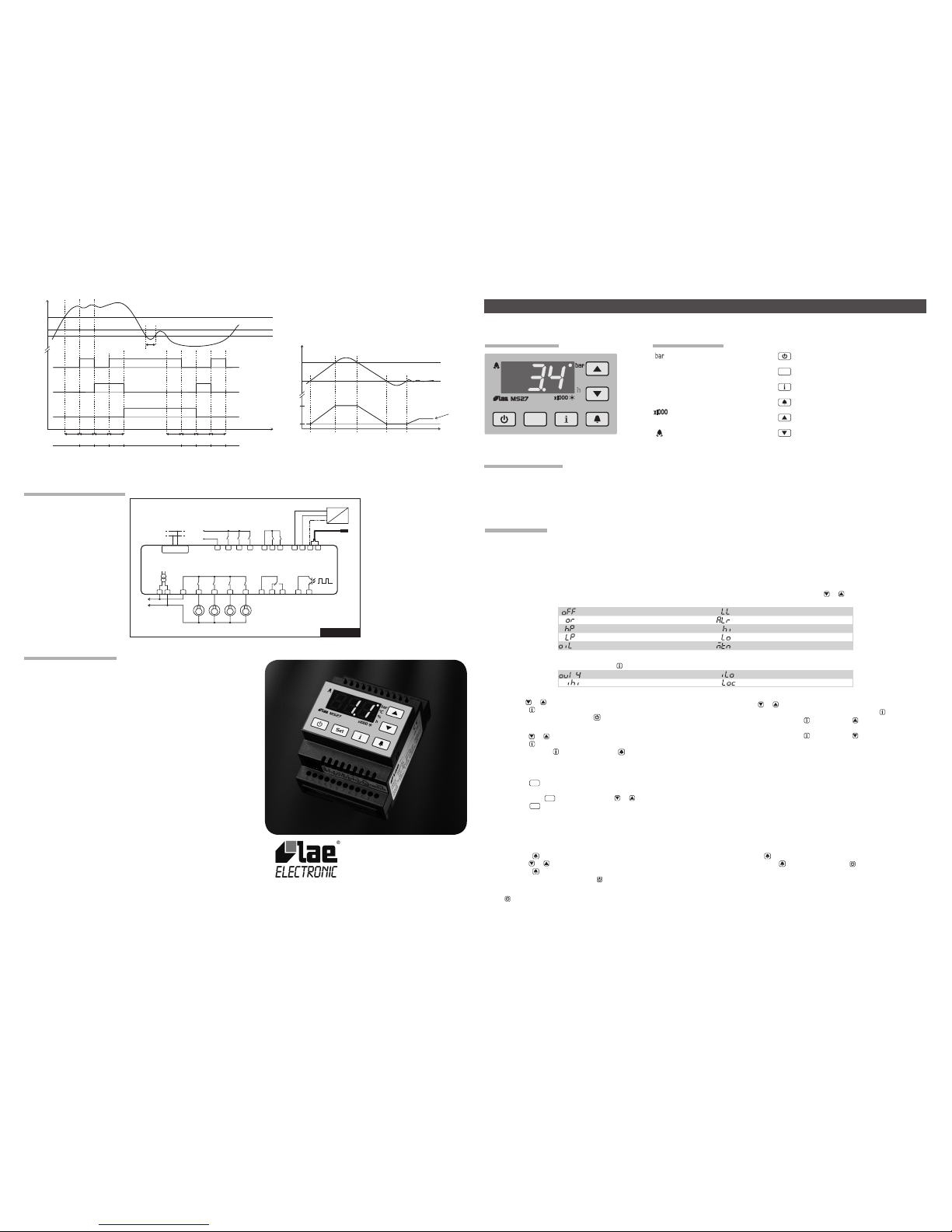
OPERATION
DISPLAY
Parameter INP selects the input used for control.
INP ■ =1-P: Input 1-P (0/4…20mA) is used to control pressure. In the setup the parameters relating to the variable to be controlled (SPL, SPH, SP,…) are
expressed in bar. In normal mode, the display shows the pressure measured in bar, or the corresponding temperature in °C, calculated according to the
refrigerant gas used (see REF). Input 2-T is disabled.
INP ■ =2-T: Input 2-T (NTC10K) is used for temperature control. In the setup the parameters relating to the variable to be controlled (SPL, SPH, SP,…) are
espressed in °C. In normal mode the display shows the temperature measured in °C, or the corresponding pressure calculated in bar. Input 1-P is disabled.
In normal mode it’s also possible to display the percentage of available power used. To modify the type of display, press or .
The following indications may also appear:
Controller in stand-by Low refrigerant level alarm
Over range or probe failure Generic alarm
High pressure alarm
High measured value alarm
Low pressure alarm Low measured value alarm
Low compressor oil alarm Periodic maintenance warning
INFO MENU
To have access to the info menu, press button . The available info is:
...
Output 1..4 state / hours of operation Min input value measured.
Max. input value measured. Keypad state (lock)
Access to menu and information displayed.
With button ■ or select the data to be displayed;
Press button ■ to display the value;
To exit from the menu, press button ■ or wait for 10seconds
Display of hours of operation of out1…out4 outputs
With button ■ or select the output;
Display the ON/OFF state of output by pressing button ■ ;
While holding down button ■ , press button to display the hours of
operation (multiplied by 1000); the “h” LED blinks.
While holding down button ■ , press button to display the hours of
operation; the “h” LED is lit.
Warning: the hours of operation of stages are not stored, ‘---‘ is ■
displayed.
Reset of hours of operation of out1…out4 outputs and of IHI, ILO recordings
With buttons ■ or select the data to be reset;
Press button ■ to display the value;
While keeping button ■ pressed, use button .
SETPOINT (display and modication of desired pressure/temperature value)
Press button ■
Set
for at least half second, to display the setpoint value;
If the second setpoint has been enabled (see ■ DI1, DI2), before its value appears, the display shows “2SP”;
By keeping button ■
Set
pressed, use button or to set the desired value (adjustment is within the minimum SPL and the maximum SPH limit).
When button ■
Set
is released, the new value is stored.
ALARM MENU
The last nine alarms can be displayed in the alarm menu, from the most recent AL1, to the least recent AL9.
Access to menu and display of stored alarm.
Press button ■ ;
With button ■ or select the data to be displayed;
Press button ■ to display the alarm type;
To exit from the menu, press button ■ or wait for 10 sec.
Reset of all stored alarm.
Press button ■ to display the type of any alarm in the list;
By keeping button ■ pressed, press button for 1 second, until the
inscription ‘non’ appears.
STAND-BY
Button when pressed for 3 seconds, allows the controller to be put on a standby or output control to be resumed (with SB=YES only).
KEYPAD LOCK
The keypad lock avoids undesired, potentially dangerous operations, which might be attempted when the controller is operating in a public place. In the INFO
menu, set parameter LOC=YES to inhibit all functions of the buttons. To resume normal operation of keypad, adjust setting so that LOC=NO.
INSTALLATION
The controller, size 71x97x61 mm (WxHxD), is to be secured to a DIN rail in such a position as to ensure that no liquid inltrates causing serious damage ■
and compromising safety.
Make sure that electrical connections comply with the paragraph “wiring diagrams”. To reduce the effects of electromagnetic disturbance, keep the sensor ■
and signal cables well separate from the power wires.
Connect a pressure transmitter with output 0/4..20mA to input 1-P. Whenever control takes place through temperature, connect an NTC10K probe (part No. ■
LAE SN4…) to input 2-T.
%
°C
h
Set
Pressure display in bar
°C
Temperature display in °C
%
Percentage of use of available power
h
Hours of operation (LED lit)
h
Thousands of hours of operation
(LED blinking)
Alarm
Stand-by button
Set
Setpoint button
Info button
Alarm display button
Increase button
Decrease button
Fig.1 - Front Panel
Thank you for having chosen an LAE electronic product. Before installing the instrument, please read this instruction booklet carefully in order to ensure safe
installation and optimum performance.
MS27 INSTRUCTIONS FOR USE
DESCRIPTION
INDICATIONS
Page 2
CONTROL
OUTPUT CONFIGURATION
Outputs are congured with parameters OC1, OC2, OC3, OC4. Parameter OCx controls the operation of output OUTx: OCx=1…100 indicates the power in
percentage over the total power, of the compressor connected to OUTx. With OCx= -1, output OUTx is associated to a stage, which is active when the relay is
closed. With OCx= -2, output OUTx is associated to a stage, which is active when the relay is open. With OCx=0, output OUTx is not used for control.
Warning: the output associated to the compressor motor must always be wired in the terminals located before the terminals where the outputs controlling the
stages are. Example: in a system with two compressors of different power (the rst with 60% of total power, the second with 40%), each compressor having a
stage, the conguration of outputs is as follows: OC1 = 60, OUT1 is connected to the motor of compressor 1 of power equal to 60% of total power. OC2 = -1,
OUT2 is connected to the stage of compressor 1, the stage is active when the relay is closed. OC3 = 40, OUT3 is connected to the motor of compressor 2 of
power equal to 40% of total power. OC4 = -1, OUT4 is connected to the stage of compressor 2.
CONTROL ALGORITHM
Parameter CM provides the control algorithm.
CM ■ =ROT: rotation of outputs of equal power. This algorithm minimises the number of starts/stops per hour of each load. When the system calls for more power,
the output which has been off for longer will be activated. When demand for power decreases, the output which has been on for longer will be switched off. When
an output remains active for more than LRT minutes, the controller looks for an inactive output fullling the requirements to be activated (less hours of operation,
minimum off time elapsed,…) and the rotation of the two outputs will take place. In this way, an equal sharing of the total operation time among all loads will be
achieved (see Fig. 2). Note:the compressor rotation algorithm assumes that compressors have got an equal power. In this case, parameter OCx is used only to
dene if output OUTx either controls a compressor or a stage. So, if the value is positive, it will have no effect on OCx, regardless of what you program. Example:
in a system consisting of four compressors, each will have a power equal to 25% of the total value, regardless of the value programmed to OCx.
CM ■ =SEN: sequential activation of the enabled outputs. The outputs are switched on/off with xed sequence, from output 1 to output 4 (see Fig. 3).
CM ■ =PO: optimisation of the available power. The controller combines the outputs in such a way as to obtain a ne control, both in case of calls for more
power and less power. Example: OC1=10, OC2=20, OC3=30, OC4=50. If a capacity of 90 is required, outputs OUT1, OUT3, OUT4 (10+30+50) are switched
on. If a capacity of 50 is required, outputs OUT2 and OUT3 (20+30) are switched on (see Fig. 4).
CONFIGURATION PARAMETERS
To get access to the parameter conguration menu, press button ■
Set
+ for 5 seconds;
with button ■ or select the parameter to be modied;
press button ■
Set
to display the value;
by keeping button ■
Set
pressed, use button or to set the desired value;
when button ■
Set
is released, the newly programmed value is stored and the following parameter is displayed;
to exit from the setup, press button ■ or wait for 30 seconds.
Note: re-programming some parameters causes a complete re-conguration of the controller operation. So please put the controller on stand-by, if you have
to modify the parameters relating to the output conguration or the selection of the control algorithm.
(In the parameter description, we refer to ‘pressure control’. In case of temperature based control, please replace the word ‘pressure’ with ‘temperature’ and
‘bar’ with ‘°C’).
PAR RANGE DESCRIPTION
INP 1-P, 2-T Input selection for control
1-P: input 1-P is used for pressure control; input 2-T is disabled.
2-T: input 2-T is used for temperature control; input 1-P is disabled.
INP=1-P
MPI 0MA, 4MA Min. current input range.
0MA: input 0…20mA; 4mA: input 4…20mA
RLO -1.0…RHI bar Min. scale range.
RLO takes the minimum value measured by the transmitter (corresponding to 0/4mA).
RHI RLO...45.0bar Max. scale range.
RHI takes the maximum value measured by the transmitter (corresponding to 20mA).
OS1 -12.0..12.0bar Probe offset
REF 404,507,22,134 Refrigerant used. It allows Pressure - Temperature conversion.
404=R404A, 507=R507, 22=R22, 134=R134A
SPL RLO…SPH Minimum limit for SP and 2SP setting
SPH SPL…RHI Maximum limit for SP and 2SP setting
SP SPL...SPH Main setpoint, indicates the pressure to be maintained.
2SP SPL...SPH Alternate Setpoint.
Pressure refence point is 2SP if DI1 (DI2) = 2SP and the corresponding input is active.
DBL -10.0...0.0bar Lower neutral zone.
The state of outputs remains unchanged as long as pressure is within the band SP+DBL
and SP+DBH.
DBH 0.0...10.0bar Higher neutral zone.
LON 0...250s Load start delay.
Pressure must remain higher than SP+DBH for LON seconds before the next load is switched on.
LOF 0...250s Load stop delay.
Pressure must remain lower than SP+DBL for LOF seconds before the next load is switched off.
SON 0...250s Stage start delay.
Pressure must remain higher than SP+DBH for SON seconds before the next stage is switched on.
SOF 0...250s Stage stop delay.
Pressure must remain lower than SP+DBL for SOF seconds before the next stage is switched off.
PB 0...20.0bar Proportional band (PWM output control, see Fig. 5).
Zone above setpoint in which the PWM output is activated proportionally.
Example: pressure < SP, PWM=0%; pressure=SP+PB/2, PWM=50%; pressure>SP+PB, PWM=100%.
IT 0...250s Integral action time (control of PWM output, see Fig. 5).
The greater the IT value, a more stable control takes place.
CM ROT,
SEN,
PO
Selection of control algorithm.
ROT: rotation of equal power outputs. SEN: sequential activation of outputs.
PO: optimisation of available power.
OC1,
OC2,
OC3,
OC4
-2...100 Control of output 1, 2, 3, 4.
1…100: power (percentage of total) of the load connected to output OUTx (x=1, 2, 3, 4);
0: output OUTx not used;
-1: output OUTx connected to a stage, which is activated when the contact is closed.
-2: output OUTx connected to a stage, which is activated when the contact is open.
MLS 0...30min Minimum off time of loads.
Minimum time which must elapse between when the load is switched off and when it’s switched on again.
LRT 0...120min Time of forced rotation of loads (only with CM=ROT).
This parameter, if greater than 0, provides the operation time of a load after which the controller takes into
account the possibility of rotation of two outputs.
DPU 0...120min Start delay.
Delay between the time when the controller is switched on when the outputs are activated, in order for the
compressor crankcases to warm up.
SCD 0...100 % Down Scaling.
It indicates the maximum per cent power usable during an alarm with enabled down scaling action.
ALA RLO...AHA Low value measured alarm threshold.
AHA ALA...RHI High value measured alarm threshold.
AID 0...120min High/Low alarm delay.
D1M
D2M
NON,
SBY,
2SP,
ALR
Function of digital input DI1, DI2.
NON: input disabled;
SBY: when input DI1 (DI2) is active, the controller is put on a stand-by.
2SP: when input DI1 (DI2) is active, the control setpoint is 2SP.
ALR: when input DI1 (DI2) is active, the controller detects a generic alarm which causes the display to show
ALR, to load to be switched off and control to be stopped. When the alarm is over, the controller resumes output
control automatically (automatic reset).
D1C
D2C
OPN,
CLS
Activation of digital input DI1, DI2.
OPN: active input is open;
CLS: active input is closed
DxM NON,HP, LP,
OIL, LL, ALR
Function of digital input DI3, DI4, DI5.
NON: input disabled. HP: high pressure alarm. LP: low pressure alarm. OIL: low compressor oil level. LL: low
refrigerant level alarm. ALR: generic alarm.
DxC OPN, CLS Activation of digital input DI3, DI4, DI5 (see D1C).
DxD 0...120min Activation delay of alarm DI3, DI4, DI5.
The digital input must remain in the activation condition for this time before the alarm is detected.
DxA DSP,
SAR,
SMR
Reaction following alarm DI3, DI4, DI5.
DSP: alarm display.
SAR: in addition to the alarm displayed, a down scaling (SCD) is activated and control is stopped. When the
alarm is over, the controller resumes output control automatically (automatic reset).
SMR: in addition to alarm displayed, all loads are switched off and control is stopped. When the alarm is over,
control is resumed but only after the alarm has been acknowledged by pressing button (manual reset).
MTC 0...600
(x100hours)
Maintenance.
When the operation hours of any load achieve this value, a maintenance warning will ash on display. To eliminate
this warning, after performing maintenance, rest the hour counters as described in paragraph “info menu”.
SB NO/YES Stand-by button enabling.
TLD 1...30min Delay for min / max input loggin.
SND NO/YES Alarm buzzer enabling
ADR 1...255 MS27 address for PC communication.
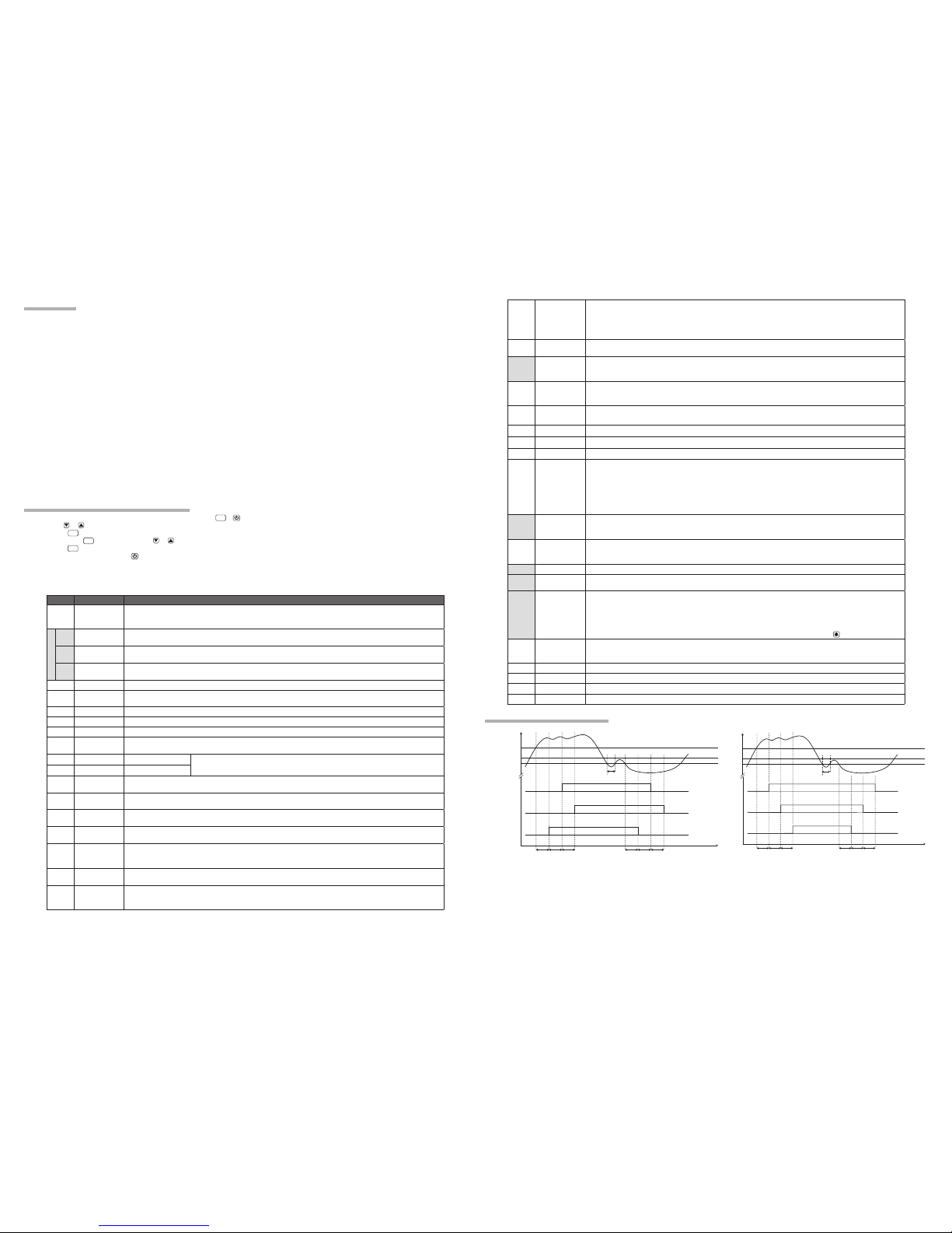
OPERATION EXAMPLES
SP
SP+DBH
Pressure
Time
SP+DBL
OUT1
OFF for10min
OUT2
OFF for7min
OUT3
OFF for15min
LON LON LON
LOF
t<LOF
LOF LOF
CM=ROT
OC1=33
OC2=33
OC3=33
OC4=0
OFF
OFF
OFF
ON
ON
ON
Fig.2 Control by rotationof outputs of equal power
Load
start
Neutral
zone
Load
stop
Time
OUT1
OUT2
OUT3
LON LON LON
LOF LOF LOF
OFF
OFF
OFF
ON
ON
ON
CM=SEN
OC1=20
OC2=30
OC3=50
OC4=0
Fig.3 Control bysequential activation of outputs
Load
start
Neutral
zone
Load
stop
t<LOF
SP+DBH
Pressure
SP+DBL
SP
 Loading...