

Page 1
Thank you for having chosen an LAE electronic product. Before installing the instrument, please read this instruction booklet carefully in order to
ensure maximum performance and safety.
1. INSTALLATION
1.1 The LDU15, size 77x35x77 mm (WxHxD), is inserted into the panel through a hole measuring 71x29 mm and is fixed by
pressing gently into the relative clamps. The rubber gasket should be inserted between the instrument frame and the panel, checking
that it adheres perfectly in order to prevent infiltration.
1.2 The instrument should work with room temperatures between -10°.. +50°C and relative humidity between 15%.. 80% inclusive.
Supply voltage, switched powers and connection set-up should scrupulously comply with the indications given on the container. To
reduce the effects of electromagnetic disturbance, keep the sensor and signal cables well separate from the power wires.
1.3 The sensor T1 measures the air temperature and activates in the thermostat control cycle; it should be placed inside the appliance
in a point that truly represents the temperature of the stored product.
CAUTION: should the relays have to changeover a heavy load frequently, it is advisable to contact the manufacturer for indications on the lifetime
of the contacts.
Whenever products must be kept within very severe specifications or the products have considerable value, the use of a second instrument is
recommended, which activates upon or warns of any malfunction.
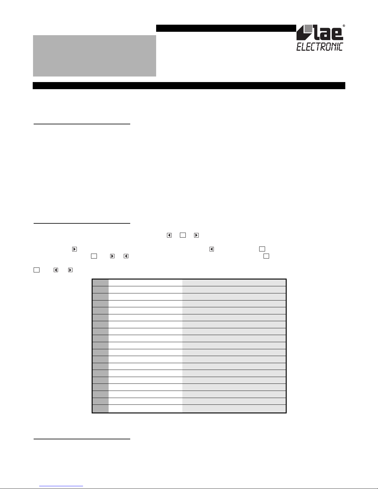
2. CONFIGURATION
The controller or regulator is adapted to the controlled system by suitably programming the configuration parameters, that is, through
the setup. The setup is accessed by pressing the buttons + + in succession and keeping them pressed simultaneously for 3
seconds. The available parameters appear in table 1 as shown below.
Press the button to pass from one parameter to the next and the button to go back. Press to display the value correlated to
the parameter and press and or simultaneously to change it. Exit from setup is by pressing or is automatic after 30 seconds
of not using the keypad. Setpoint SP display and adjustment is also possible during normal operation of the controller by pressing the
and or buttons. The range in any case remains within the limits SPL and SPH.
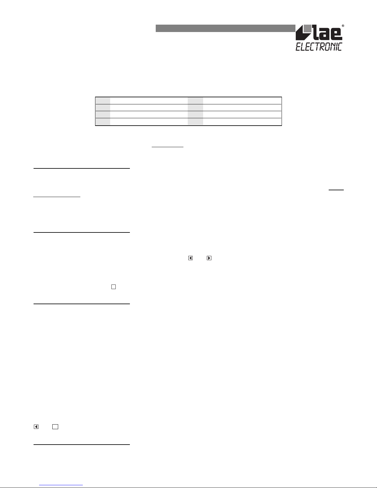
3. DISPLAYS
Upon switching on, just the central line (autotest) appears on the display for approximately three seconds and the subsequent
indications depend on the operating status of the controller. Table 2 gives the indications associated with the various states.
The temperature measured by the sensor T1 is handled by the microprocessor so that it is displayed in the most representative way. In
other words, the parameter SCL is used to select the display in °C with 0.1/1° auto-range (SCL=1°C), in °C with 1° fixed resolution
SET
A
UX
SET
SET
SET
INSTRUCTIONS FOR INSTALLATION AND USE.
LDU15
SPL -10.0.. SPH [°] Minimum temperature set point
SPH SPL.. +25.0 [°] Maximum temperature set point
SP SPL.. SPH [°] Effective temperature set point
HYS +0.1.. +10.0 [°] Thermostat hysteresis
CRT 0.. 30 [min] Compressor rest time
CDC 0.. 10 Compressor regulation with sensor T1 failure
DFR 0.. 24 Defrosting frequency /24h
DTO 1.. 120 [min] Defrosting duration
DDY 1.. 60 [min] Defrosting display control
ATL -12.0.. 0 [°] Low alarm differential
ATH 0.. +12.0 [°] High alarm differential
ATD 0.. 120 [min] Temperature alarm delay
ACC 0.. 52 [weeks] Condenser periodic cleaning
OAU NON/SBY/MAN/DEF/ALR Auxiliary output mode of operation
BAU NON/SBY/MAN Auxiliary button mode of operation
SCL 1°C/2°C/°F Readout scale
OS1 -12.5.. +12.5 [°] Sensor T1 correction
SIM 0.. 100 Display slowdown
ADR 1.. 255 Peripheral address
TABLE 1
Page 2
(SCL=2°C) or in Fahrenheit (SCL=°F). The measured temperature may be corrected with a fixed offset by assigning a value other than
0 to the parameter OS1. Furthermore, prior to display, the temperature is treated by an algorithm that allows the simulation of a thermal
mass directly proportional to the SIM value. The result is a reduction in the fluctuation of the displayed value.
The status of the compressor and auxiliary outputs is shown through the respective dots on the display.
TABLE 2
CAUTION: upon changing the display scale SCL, it is ABSOLUTELY necessary to reconfigure the parameters related to the absolute (SPL, SPH,
SP) and differential (HYS, ATL, ATH, OS1) temperatures.
4. THERMOSTAT CONTROL
4.1 Thermostat control is based on comparing the temperature T1, the set point SP and the hysteresis HYS.
Example: SP= 2.0; HYS= 1.5, relay Off with T1= +2.0° and On with T1= +3.5°.
The compressor only switches On again if the minimum Off time CRT since the previous switchover has elapsed. Whenever a ver
y
small hysteresis HYS
must be maintained, we advise assigning a suitable value to CRT in order to reduce the number of starts/hour.
4.2 If sensor T1 fails, the output is controlled for a fixed time established with CDC; this determines the activation time of the output
within 10-minute cycles.
Example: CDC=06, 6 minutes On, 4 minutes Off.
5. DEFROSTING
Defrosting starts automatically when the internal timer reaches the necessary time to obtain the defrosting frequency set with DFR. For
example, with DFR=4 defrosting occurs once every 6 hours. With DFR=0 the timed defrosting function is cut out. When the controller
is put on a standby, the timer count is frozen.
Defrosting may also be induced manually by pressing the buttons and simultaneously.
The internal timer is set to zero when the instrument is switched on, at each subsequent defrost start and, if in the standby mode,
whenever standby lasts for at least the time set in DTO.
Defrosting occurs upon stopping the compressor and, if OUA=DEF, upon activating the defrost heater through the auxiliary relay for
the time DTO. During defrosting appears on the display and remains there after the end of defrosting for the time set in DDY.
6. ALARMS
With LDU15 correct operation of the thermostat, sensor and the periodic warning of condenser cleaning can be checked. The alarm
warnings are given on the display with explicit indications (table 2) and, with OAU=ALR, also on the auxiliary relay (not for condenser
cleaning).
The alarm warning is removed from the display upon pressing any button for two seconds, but if the alarm persists, it reappears after
30 minutes. Operation of the various sections is given in detail below.
6.1 The parameters ATL and ATH define two differential temperatures that, referred to the set point, determine the temperature alarm
thresholds. ATL establishes the alarm differential for temperatures below set point, ATH the alarm differential for temperatures above
set point + hysteresis. Putting one or both differentials to 0 cuts out the corresponding alarm.
Example: SP= 2.0, HYS= 1.5, ATL= -5.0, ATH= 5.0; the alarm thresholds are fixed at -3.0° and +8.5°.
The alarm warning may be immediate or delayed by the time ATD whenever this is greater than 0. The high temperature alarm is
bypassed during defrosting.
6.2 Assigning a value greater than 0 to the parameter ACC enables the indication for periodic cleaning of the condenser. In other
words, when the count of compressor hours of operation reaches the equivalent in weeks set with ACC, an indication for cleaning
appears on the display (see table 2).
Example: with ACC=16 there is a warning once every 16x7(weeks)x24(hours)=2688 hours of compressor operation, in other words,
assuming for this an operation with 5 minutes On and 5 minutes Off - after approx. 32 weeks.
The time counter may only be cleared after the programmed time has been reached. Therefore proceed as follows: press the buttons
and in sequence and hold them simultaneously.
7. AUXILIARY FUNCTIONS
The LDU15 controller comprises a button and an auxiliaries relay with functions that may be suitably combined through the parameters
OAU and BAU. The parameter OAU assigns one of the following functions to the auxiliary output: alarm warning (ALR), defrost heater
control (DEF), manual control (MAN), auxiliary loads (SBY), cut-out (NON). The parameter BAU determines the function associated
A
UX
DF
INSTRUCTIONS FOR INSTALLATION AND USE.
- autotest (3 seconds) HI high temperature alarm
2.5 sensor T1 temperature LO low temperature alarm
DF defrosting in progress E1 sensor T1 failure
OFF standby CLN Condenser cleaning
Page 3

with the button : direct control of the auxiliary relay (MAN), instrument on/off (SBY), no function (NON). A few examples of use
are given below:
Example 1, OAU=BAU=MAN: each time the button is pressed there is a changeover of the auxiliary load (e.g. interior lights).
Example 2, OAU=BAU=SBY: pressing for approx. 3 seconds changes the status of both the controller (on/standby) and the auxiliary load
(e.g. evaporator fans).
Example 3, OAU=ALR and BAU=NON: the auxiliary relay is activated during an alarm condition; the button is only used to exit from the
setup and to reset the condenser cleaning timer.
Example 4, OAU=DEF and BAU=SBY: the auxiliary relay is activated during defrost, pressing for approx. 3 seconds changes the status of
the controller (on/standby).
The controller is provided with a serial port for connection to a PC or a programmer. In the first case it is important to assign to the
parameter ADR a different value for each linked unit (peripheral address); with automatic programming, ADR should remain on 1.
WARRANTY
LAE electronic Srl guarantees its products against defects due to faulty materials or workmanship for one (1) year from the date of manufacture shown on the
container. The Company shall only repair or replace products which are shown to be defective to the satisfaction of its own technical services. The Company
shall not be under any liability and gives no warranty in the event of defects due to exceptional conditions of use, misuse or tampering.
All carriage expenses for returning the product to the manufacturer, after having obtained the latter’s permission, and for any return to the buyer shall be paid
by the buyer.
AUXAUXAUXAUXA
UX
INSTRUCTIONS FOR INSTALLATION AND USE.
Page 4

VIA PADOVA, 25
31046 ODERZO /TV /ITALY
TEL. 0422 815320 - 815303
TELEFAX 0422 814073
www.lae-electronic.com
E-mail: info@lae-electronic.com
PARTNER VENEZIA • 041 5460713
WIRING DIAGRAMS
LDU152E-A
LDU152E-A
INSTRUCTIONS FOR INSTALLATION AND USE.
 Loading...