

Page 1
We thank you for choosing an LAE controller. Before proceeding to the installation of the BIT20, please read this instructions sheet carefully; only
in this way you will obtain maximum performances and safety.
1. INSTALLATION
1.1 The BIT20 has got a size of 110x87x55 mm; it must be secured to the panel with three screws or rivets to be inserted into the suitable
slots. Protection is IP30, therefore please locate the unit in a position ensuring that no liquid infiltrates and damages the unit.
1.2 The unit must work with ambient temperature between -10°…+50°C and 15%…80% relative humidity. To reduce the effects of electromagnetic interference, locate the probe cables and the unit as away as possible from power lines.
1.3 Probes, power supply and outputs must be connected strictly according to the indications appearing on the board; the cables can pass
through the hole on the unit side. For supply voltage and maximum loads please read the label inside the enclosure.
1.4 Probe TA measures air temperature and is used for temperature control. Probe TE measures the evaporator temperature and must be
located in a place where the maximum frost growth occurs.
1.5 The flat cable of the remote display must pass through the suitable opening of the lid that also keeps the cable locked. This operation
must be performed after the lid has been lifted upwards completely.
Caution: where delicate or valuable products have to be maintained under strict conditions, please use a different controller for limit and alarm
functions.
2. CONTROL PARAMETERS
The adaptation of the BIT20 to the system that it controls is achieved through the control parameters.
BIT20B allows parameters setting
through the keypad on BIT12RU remote unit. Differently, BIT20A has been thought to provide two alternative setting methods of the control
parameters. The first one, like in the BIT20B, by means of keypad, the other method is new and allows to select all main parameters through
the combination of dipswitches located on the control unit. Operating mode selection is made via MEMORY/SELECTORS dipswitch.
2.1 M
EMORY
. In this operating mode, all control parameters are adjustable and saved into permanent memory during the SETUP. The SETUP
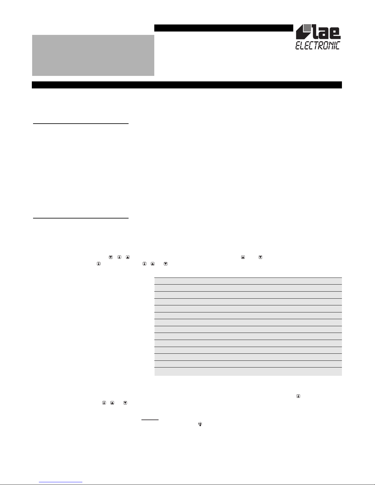
function is accessible by pressing
++
for 4 seconds. Scroll the parameter list via keys and until you achieve the desired one,
display its value by pressing and modify it via + or . The parameters available in the BIT20 are the following:
Exit from the SETUP takes place automatically after 15 seconds of no key activation.
In MEMORY mode, without having to enter the SETUP, the setpoint value SP can always be displayed by pushing key and programmed
within the SL and Sh limits via + or .
2.2 S
ELECTORS
(1)
. In this operating mode, the dipswitches and some default parameters determine control. The adjustable parameters are:
A) Setpoint: to select the setpoint range, move just one
of the range selectors to YES (-35...-20; -19...-4; -3 ...+12°C). After having done
this, by moving one or more of the setpoint modification selectors to YES (+ ), you add the value reported on their side to the setpoint range
minimum limit, obtaining in this way the actual setpoint value (see Figure 1).
B) Hysteresis: the on switching differential starts from 1°K minimum to which, through the relevant switches, you may add up to 7°K. The
thermostat hysteresis is therefore adjustable from 1 (all NO) to 8°K (all YES) in 1°K steps.
C) Defrost frequency: the number of defrosts per 24 hours ranges from a maximum of 7 and a minimum of 1 per day. Setting all switches
to NO excludes defrost.
D) Defrost duration: duration ranges from a fixed minimum of 10 minutes (all switches NO) to a maximum of 80 minutes (all YES) in 10
1 SP thermostat Off switching temperature [SL ... Sh]
2 SL minimum programmable temperature [-35 ... Sh]
3 Sh maximum programmable temperature [SL... +15°C]
4 hy thermostat On switching hysteresis [+1 ... +8°K]
5 cr minimum compressor rest time [0 ...4 minutes]
6 cF compressor safety run in case of probe failure [00=40% ... 01=100%]
7 dF number of defrosts within 24 hours [0 ... 12]
8 dt maximum defrost duration [1 ... 90 minutes]
9 dL defrost limit temperature [+1... +20°C]
10 dM defrost mode [0=off cycle; 1=electric; 2=hot gas]
11 dr drain time [0... 10 minutes]
12 th display control during defrost [0='TA' … 60 minutes='dF']
13 to offset of displayed temperature [-9... +9°K]
14 tS slowdown of displayed temperature [0 ... 20]
INSTRUCTIONS FOR INSTALLATION AND USE.
BIT20A22
BIT20B22
Page 2

minute steps.
In Figure 1 some examples of the possible combinations appear.
3. DISPLAYS
3.1 At power-up, the BIT12 shows “--“ for 4 seconds during which it performs self-check; then, the temperature measured (TA+to) appears.
By means of parameter tS it's possible to reduce the display fluctuations by simulating the behaviour of product core temperature. The
slowdown is proportionated to tS parameter value.
3.2 Under some circumstances, owing to the structure of the cabinet or air circulation, the displayed temperature does not match the most
representative product temperature. In this case, through the parameter to, temperature TA may be offset to obtain the desired readout.
3.3 To display the instantaneous temperatures TA and TE press keys or respectively.
3.4 By means of key it’s possible to display the current setpoint value both when the unit operates in MEMORY and SELECTORS
(1)
mode.
In this latter case, an attempt to modify the setpoint will cause the display to show “Lo” to warn you that setting is locked.
3.5 If parameter th is given a value greater than 0, “dF” is displayed all through defrost and after until its programmed value in minutes is
over.
4. TEMPERATURE CONTROL
Temperature control is based on the comparison between temperature TA (not affected by to), the programmed setpoint SP and the hysteresis
hY. The refrigerator off switching temperature is determined by setpoint plus differential. Ex.: setpoint= -20; hysteresis=04, relay off with
TA= -20°C and on with TA= -16°C.
The actual compressor cut-in is only possible if the minimum off time has elapsed since the last cutout. This off time is cr in MEMORY mode
and is fixed to 3 minutes in SELECTORS mode
(1)
.
If probe TA fails, the display shows “E1” and the compressor remains on for either 40% or 100% of the time, depending on the operating
mode selected. In MEMORY mode, parameter cF determines the compressor status: 00=40% (3min. on, 4min. off); 01=100% (always on).
In SELECTORS mode, selection takes place automatically according to the actual setpoint. Therefore, for setpoints lower than -10°C, the
compressor is always on, differently it works at 40%.
5. DEFROST
Defrost takes place automatically when the built-in timer matches the time needed to obtain the selected defrost spread over 24 hours. For ex.:
by setting 4 defrosts per day, defrost will be started every 6 hours. This timer is cleared when the unit is powered up and every time defrost
starts.
5.1 M
EMORY
. In this case defrost frequency is determined by parameter dF and the maximum duration by dt. When probe TE placed on the
evaporator measures temperature dL before the limit time dt has elapsed, then defrost is terminated in advance. During defrost the outputs
switch on or off depending on the defrost mode selected via parameter dM: 00=off cycle, 01=electrical, 02=hot gas.
With dF=0, timed defrosts are suspended.
With dr you can add a pause, between defrost and compressor re-start, allowing a homogeneous heat spread all over the evaporator and,
at the same time, the drain of the water formed from ice melting.
Probe TE is only active in the MEMORY mode. In the event of probe TE failure, "E2" is displayed.
5.2 S
ELECTORS
(1)
. When SELECTORS mode is on, timer count refers to the values set via the defrost switches, it doesn't keep into consideration
the temperature measured by the evaporator probe TE. Therefore defrost termination occurs when only the maximum time is achieved. In this
case, you can obtain an electrical or off cycle defrost, depending on the connected load and the drain time is fixed to 2 minutes.
5.3 Defrost may also be induced manually, by pressing the button located on the control unit or by pressing keys and simultaneously
(in mode MEMORY only).
Thanks to the normally closed contact of the defrost relay it's possible to stop the evaporator fans during defrost.
(1)
This operating mode is available in the BIT20A only.
WARRANTY
LAE electronic Srl warrant that their products are free of any defects in workmanship and materials for a period of 1 (one) year from date of production
shown on the enclosure. LAE electronic Srl shall only repair or replace those products of which defects are due to LAE electronic Srl and recognised by their
technicians. LAE electronic Srl are not liable for damages resulting from malfunctions of the products.
Defects due to exceptional operating conditions, misapplication and/or tampering will void the warranty.
All transport charges for returning the product to the manufacturer, after prior authorisation by LAE electronic Srl, and for the return to the purchaser are
always for the account of the purchaser.
INSTRUCTIONS FOR INSTALLATION AND USE.
Page 3

Figure 1
A
B
C
A. Operating mode = SELECTORS; Setpoint = +1°C (-3+4); Hysteresis = 3°K
(1+2); Defrost frequency = 4/24 hours; Defrost duration = 30 minutes
(10+20).
B. Operating mode = SELECTORS; Setpoint = -20°C (-35+1+2+4+8);
Hysteresis = 4°K (1+1+2); Defrost frequency = 6/24 hours (2+4); Defrost
duration = 60 minutes (10+10+40).
C. Operating mode = MEMORY, data are read from internal memory.
WIRING DIAGRAM
SETUP
1 SP SL... Sh 03
2 SL -35 ... Sh -03
3 Sh SL ... 15 12
4 hy 01... 08 03
5 cr 00 ... 04 03
6 cF 00... 01 00
7 dF 00... 12 06
8 dt 01 ... 90 20
9 dL 01 ...20 10
10 dM 00....02 01
11 dr 00 ... 10 03
12 th 0 … 60 10
13 to -09 ... 09 00
14 tS 0 … 20 03
VIA PADOVA, 25
31046 ODERZO /TV /ITALY
TEL. 0422 815320 - 815303
TELEFAX 0422 814073
www.lae-electronic.com
E-mail: info@lae-electronic.com
PARTNER VENEZIA • 041 5460713
INSTRUCTIONS FOR INSTALLATION AND USE.
 Loading...