

Page 1
INSTRUCTIONS
FOR INSTALLATION AND USE.
BEDIENUNGS-
UND EINBAUANLEITUNGEN.
VIA PADOVA, 25
31046 ODERZO /TV /ITALY
TEL. 0422 815320 - 815303
TELEFAX 0422 814073
www.lae-electronic.com
E-mail: info@lae-electronic.com
PARTNER VENEZIA • 041 5460713
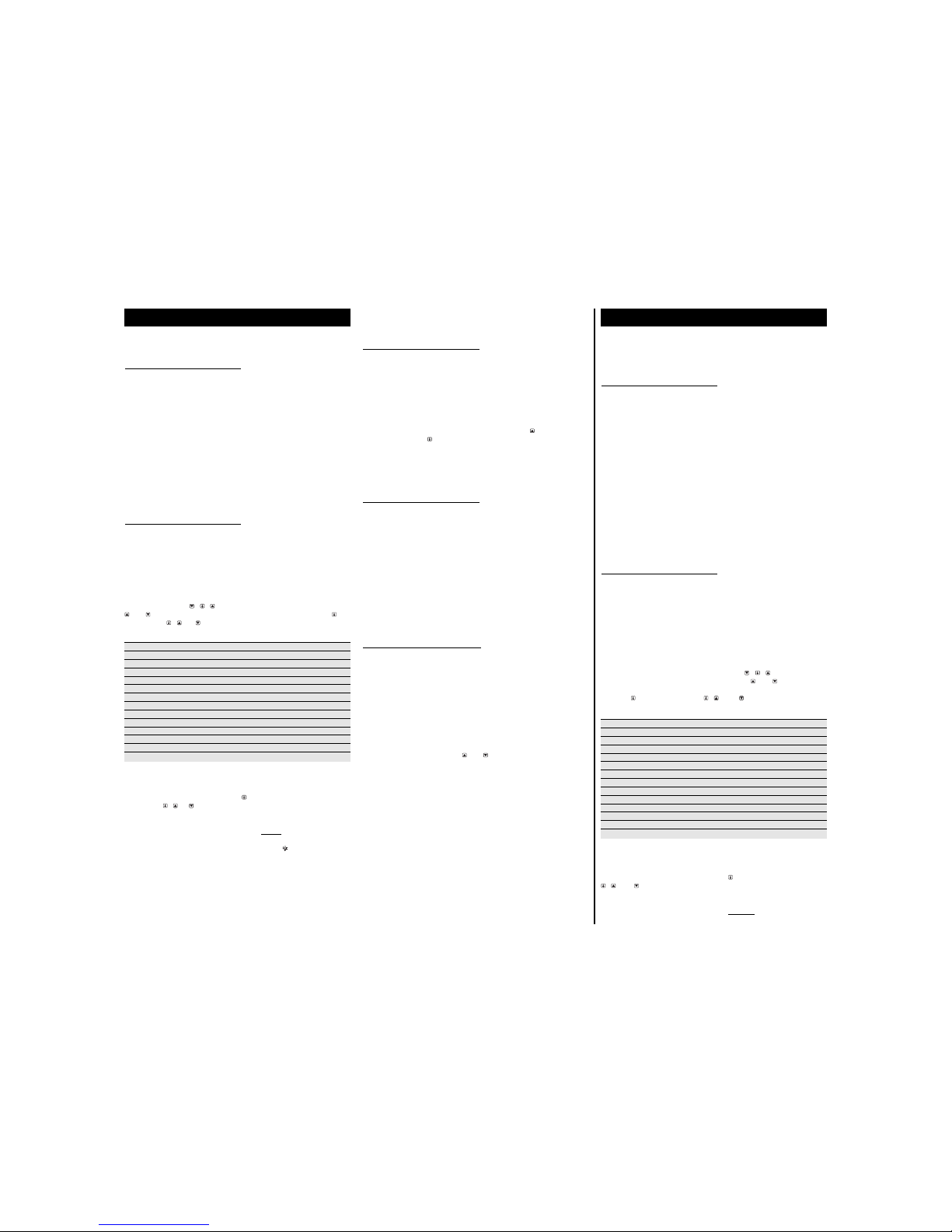
WIRING DIAGRAM - ANSCHLUßSCHEMA
BIT20A11
BIT20B11
SETUP
1 SP SL ... Sh 03
2 SL -35 ... Sh -03
3 Sh SL ... 15 12
4 hy 01 ... 08 03
5 cr 00 ... 04 03
6 cF 00... 01 00
7 dF 00 ... 12 06
8 dt 01... 90 20
9 dL 01 ... 20 10
don't change/nicht ändern
10 dM 00 ... 02 01 don't change/nicht ändern
11 dr 00 ... 10 00
don't change/nicht ändern
12 th 0 … 60 10
13 to -09 ... 09 00
14 tS 00 ... 20 03
WARRANTY
LAE electronic Srl warrant that their products are free
of any defects in workmanship and materials for a
period of 1 (one) year from date of production shown
on the enclosure. LAE electronic Srl shall only repair
or replace those products of which defects are due to
LAE electronic Srl and recognised by their
technicians. LAE electronic Srl are not liable for
damages resulting from malfunctions of the products.
Defects due to exceptional operating conditions,
misapplication and/or tampering will void the
warranty.
All transport charges for returning the product to the
manufacturer, after prior authorisation by LAE
electronic Srl, and for the return to the purchaser are
always for the account of the purchaser.
GARANTIE
LAE electronic Srl garantiert, daß seine Produkte für
die Dauer eines Jahres vom am Gehäuse
angegebenen Herstellungsdatum ab frei von
Material- und Konstruktionsfehlern sind. LAE
electronic Srl wird die defekten Geräte nur dann
ersetzen oder reparieren, wenn eine Überprüfung
des Fehlers von einem LAE-Fachmann durchgeführt,
und ein Herstellersfehler festgestellt wurde. Für
Geräte, die durch falschen Gebrauch oder falschen
Einbau defekt sind, gilt diese Garantie nicht. Die
Kosten für den Hin- und Rücktransport der defekten
Produkte gehen immer zu lasten des Käufers. Ein
Produkt darf nicht ohne Genehmigung von LAE
electronic Srl zurückgeschickt werden.
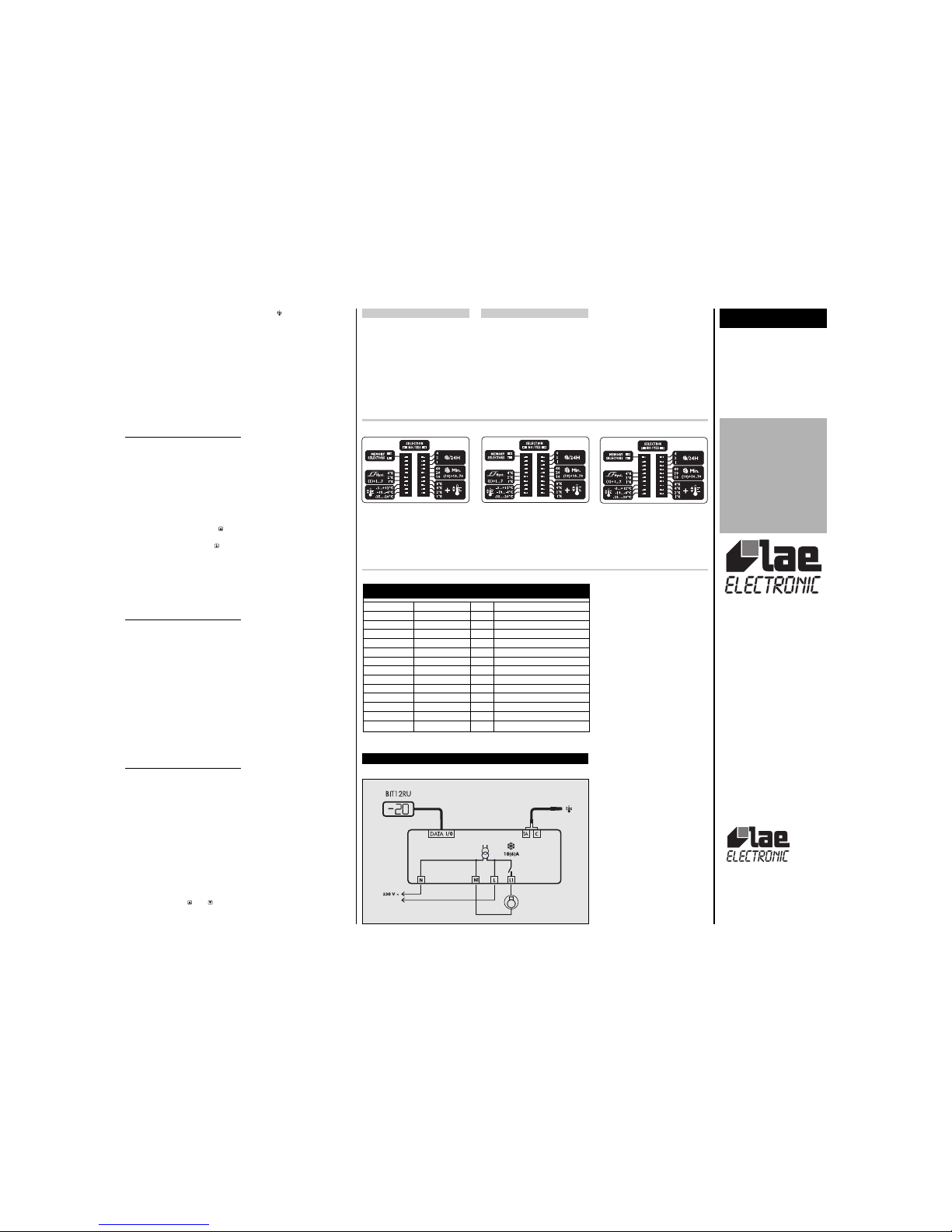
Figure 1 / Bild 1
A. Operating mode = SELECTORS; Setpoint = +1°C (-3+4); Hysteresis =
3°K (1+2); Defrost frequency = 4/24 hours; Defrost duration = 30
minutes (10+20).
A. Betriebsart= SELECTORS; Sollwert= +1°C (-3+4); Schalthysterese =
3°K (1+2); Abtauhäufigkeit= 4/24 Stunden; Abtaudauer= 30 Minuten
(10+20).
B. Operating mode = SELECTORS; Setpoint = -20°C (-35+1+2+4+8);
Hysteresis = 4°K (1+1+2); Defrost frequency = 6/24 hours (2+4);
Defrost duration = 60 minutes (10+10+40).
B. Betriebsart= SELECTORS;Sollwert=-20°C (-35+1+2+4+8);
Schalthysterese = 4°K (1+1+2); Abtauhäufigkeit=6/24 Stunden(2+4);
Abtaudauer= 60 Minuten (10+10+40).
C. Operating mode = MEMORY, data are read from internal memory.
C. Betriebsart= MEMORY, die Daten werden vom internen Speicher
gelesen.
A
B
C
eines oder mehrerer Sollwertmodifizierungsschalter (+ ) werden die Werte der
betätigten Schalter zur unteren Sollwertbereichgrenze addiert. Dadurch wird der
tatsächliche Sollwert erzielt (siehe Bild 1).
B) Schalthysterese: Die Einschaltdifferenz liegt zwischen 1°K minimal, zu der
durch die dazugehörigen Schalter bis zu 7°K addiert werden können. Die
Thermostat-Schalthysterese ist deshalb zwischen 1 (alle Schalter auf NO) und
8°K (alle Schalter auf YES) in 1°K-Schritten programmierbar.
C) Abtauhäufigkeit: Die Anzahl von Abtauungen pro 24 Stunden liegt
zwischen 7 maximal und 1 Abtauung minimal pro Tag. Werden alle Schalter
auf NO gestellt, so wird die Abtaufunktion ausgeschlossen.
D) Abtaudauer: Die Dauer liegt zwischen 10 Minuten minimal (alle Schalter auf
NO) und 80 Minuten maximal (alle Schalter auf YES) in 10-Minuten-Schritten.
Im Bild 1 werden einige Beispiele der möglichen Kombinationen angegeben.
3. ANZEIGEN
3.1 Beim Einschalten zeigt der BIT12 "--" in den ersten 4 Sekunden, wobei er
eine Selbstkontrolle durchführt. Danach erscheint die gemessene Temperatur
TA+to in der Anzeige. Durch den Parameter tS werden die
Anzeigeschwankungen durch die Simulierung des Benehmens der
Produktkerntemperatur abgestumpft. Die Verlangsamung ist proportional zu dem
Wert des Parameters tS.
3.2 In einigen Fällen, je nach Struktur der Zelle oder Luftschichtung, kann die
angezeigte Temperatur nicht mit der für das Produkt wichtiger Temperatur
übereinstimmen. In einem solchen Fall, kann die Temperatur TA durch den
Parameter to geändert werden, um die gewünschte Anzeige zu erzielen.
3.3 Durch Drücken der Taste wird die augenblickliche Temperatur TA
angezeigt.
3.4 Durch Betätigung der Taste erscheint der gegenwärtige Sollwert, wenn der
Regler sowohl in MEMORY- also auch SELECTORS
(1)
-Betriebsart arbeitet. In diesem
letzten Fall, wenn man versucht, den Sollwert zu ändern, erscheint "Lo" (locked) im
Display, um anzuzeigen, daß die Programmierung mit der Tastatur gesperrt ist.
3.5 Bei Programmierung eines Wertes größer als 0 für den Parameter th
erscheint "dF" während der gesamten Abtauphase in der Anzeige und danach,
bis der einprogrammierte Wert in Minuten abgelaufen ist.
4. TEMPERATURSTEUERUNG
Die Temperatursteuerung stützt sich auf den Vergleich der Temperatur TA (nicht
durch to beeinflußt) mit dem programmierten Sollwert SP und Schalthysterese
hY. Die Verdichter-Einschalt-Temperatur wird durch Addieren der
Schalthysterese zum Sollwert bestimmt. Beispiel: Sollwert= -20; Schalthysterese=
04; Relais Aus bei TA=-20°C und Ein bei TA= -16°C.
Der tatsächliche Verdichterwiederanlauf erfolgt erst, nachdem die minimale
Auszeit nach der letzten Abschaltung vergangen ist. Diese Auszeit ist cr bei der
MEMORY-Bestriebsart und 3 feste Minuten bei SELECTORS-Betriebsart.
Bei Fehler des Fühlers TA zeigt die Anzeige "E1" an, und der Verdichter bleibt
entweder während 40% oder 100% der Zeit in Betrieb, abhängig von der
gewählten Betriebsart. Bei MEMORY bestimmt der Parameter cF den
Verdichterzustand: 00=40% (3 Min. Lauf, 4 Min. Pause); 01=100%
(Dauerlauf). Bei SELECTORS erfolgt eine automatische Wahl der Betriebszeit
gemäß dem Sollwert. Ist der Sollwert tiefer als -10°C so läuft der Verdichter auf
Dauerlauf, liegt der Sollwert darüber, dann läuft er 40% der Zeit.
5. ABTAUUNG
Die Abtauung über Verdichterpause erfolgt automatisch, sobald der eingebaute
Abtau-Timer die programmierte Häufigkeit während 24 Stunden erreicht hat.
Beispiel: Durch Programmierung von 4 Abtauungen pro Tag, startet die
Abtauung alle 6 Stunden. Der Timer wird beim Einschalten des Reglers und
beim Start jeder Abtauung geloschen.
5.1 M
EMORY. In diesem Fall wird die Abtauhäufigkeit vom Parameter dF und
die maximale Dauer von dt bestimmt. Mit dF=0 werden zeitliche Abtauungen
unterdrückt.
Die Parameter dL, dM und dr haben eine besondere Bedeutung und sollen ihre
Werkeinstellungen behalten und nicht geändert werden.
5.2 S
ELECTORS
(1)
. Bei Benutzung der SELECTORS-Betriebsart bezieht sich die
Zeitberechnung auf die eingestellten Werte der Abtau-DIP-Schalter. Bei dieser
Betriebsart wird die Abtauung fest um 2 Minuten verlängert.
5.3 Es ist auch möglich, eine Handabtauung einzuleiten, indem man die dafür
vorgesehene Taste an der Kontrolleinheit drückt oder durch gleichzeitige
Betätigung der Tasten und (nur bei MEMORY-Betriebsart möglich).
(1)
Diese Betriebsart ist nur bei BIT20A verfügbar.
Page 2
D) Defrost duration: duration ranges from a fixed minimum of 10 minutes
(all switches NO) to a maximum of 80 minutes (all YES) in 10 minute steps.
In Figure 1 some examples of the possible combinations appear.
3. DISPLAYS
3.1 At power-up, the BIT12 shows “--“ for 4 seconds during which it performs
self-check; then, the temperature measured (TA+to) appears. By means of
parameter tS it's possible to reduce the display fluctuations by simulating the
behaviour of product core temperature. The slowdown is proportionated to tS
parameter value.
3.2 Under some circumstances, owing to the structure of the cabinet or air
circulation, the displayed temperature does not match the most representative
product temperature. In this case, through the parameter to, temperature TA
may be offset to obtain the desired readout.
3.3 To display the instantaneous temperature TA press key .
3.4 By means of key it’s possible to display the current setpoint value both
when the unit operates in MEMORY and SELECTORS
(1)
mode. In this latter case,
an attempt to modify the setpoint will cause the display to show “Lo” to warn
you that setting is locked.
3.5 If parameter th is given a value greater than 0, “dF” is displayed all
through defrost and after until its programmed value in minutes is over.
4. TEMPERATURE CONTROL
Temperature control is based on the comparison between temperature TA (not
affected by to), the programmed setpoint SP and the hysteresis hY. The
refrigerator off switching temperature is determined by setpoint plus differential.
Ex.: setpoint= -20; hysteresis=04, relay off with TA= -20°C and on with TA=
-16°C.
The actual compressor cut-in is only possible if the minimum off time has elapsed
since the last cutout. This off time is cr in MEMORY mode and is fixed to 3
minutes in SELECTORS mode
(1)
.
If probe TA fails, the display shows “E1” and the compressor remains on for
either 40% or 100% of the time, depending on the operating mode selected. In
MEMORY mode, parameter cF determines the compressor status: 00=40%
(3min. on, 4min. off); 01=100% (always on). In SELECTORS mode, selection
takes place automatically according to the actual setpoint. Therefore, for
setpoints lower than -10°C, the compressor is always on, differently it works at
40%.
5. DEFROST
Off cycle defrost takes place automatically when the built-in timer matches the
time needed to obtain the selected defrost spread over 24 hours. For ex.: by
setting 4 defrosts per day, defrost will be started every 6 hours. This timer is
cleared when the unit is powered up and every time defrost starts.
5.1 M
EMORY. In this case defrost frequency is determined by parameter dF and
the duration by dt. With dF=0, timed defrosts are suspended.
Parameters dL, dM and dr have got a particular meaning and must not
therefore be set to values different from factory settings.
5.2 S
ELECTORS
(1)
. When SELECTORS mode is on, timer count refers to the
values set via the defrost switches. In this operating mode the defrost duration set
is extended by a fixed time of 2 minutes.
5.3 Defrost may also be induced manually, by pressing the button located on
the control unit or by pressing keys and simultaneously (in mode MEMORY
only).
(1)
This operating mode is available in the BIT20A only.
DEUTSCH
Wir bedanken uns , daß Sie einen LAE-Regler gekauft haben. Bevor der BIT20
installiert wird, lesen Sie bitte aufmerksam diese Bedienungsanleitungen durch.
Dadurch werden Sie seine Möglichkeiten am besten ausnutzen und die maximale
Betriebssicherheit erreichen.
1. INSTALLATION
1.1 Der BIT20 hat eine Maße von 110x87x55 mm. Die Befestigung am Paneel
erfolgt durch drei Schrauben oder Nieten, die in die dafür vorgesehenen
Öffnungen eingesteckt werden sollen. Die Schutzart beträgt IP30, darum muß
das Gerät so installiert werden, daß keine Flüssigkeit oder Feuchtigkeit, die
funktionsgefährlich sein kann, in das Gerät eindringen darf.
1.2 Der Einsatzbereich des Gerätes liegt zwischen -10°...+50°C und
15%...80% relativer Feuchte. Um Einwirkungen von elektro-magnetischen
Störungen zu vermindern, sollen das Fühlerkabel und das Gerät von
Starkstromleitungen ferngehalten werden.
1.3 Der Fühler, die Versorgungsspannung und der Ausgang sind gemäß dem
Anschlußschema auf der Platine des Gerätes anzuschließen. Die Kabel können
durch das Loch an der Seite des Gehäuses geführt werden. Bitte achten Sie auf
die richtige Versorgungsspannung und auf die maximale Schaltleistung des
Relais, die auf dem Aufkleber innerhalb des Gehäuses aufgeführt sind.
1.4 Das Flachkabel für die Fernanzeige muß durch die dazugehörige Öffnung
des Deckels, die auch das Kabel festhält, geführt werden. Diese Aktion kann
vorgenommen werden, nachdem der Deckel vollständig aufgeklappt worden ist.
Achtung: Wo kritische oder hochwertige Erzeugnisse bei einer bestimmten
Temperatur gehalten werden müssen, muß ein separater Thermostat zur Sicherheit und
Alarmkontrolle verwendet werden.
2. KONTROLLPARAMETER
Die Anpassung des Reglers zum gesteuerten System erfolgt über die
Kontrollparameter. Der BIT20B ermöglicht eine Parameterprogrammierung durch
die Tastatur der BIT12RU-Ferneinheit. Andernfalls wurde der BIT20A so gestaltet,
daß zwei alternative Programmiersysteme für die Kontrollparameter angeboten
werden können. Das erste System funktioniert wie beim BIT20B durch eine
Tastatur; das andere System ist neu und ermöglicht die Auswahl aller
Hauptparameter durch die Stellung von DIP-Schaltern, die auf der Kontrolleinheit
angebracht sind. Die Betriebsart wird über den MEMORY/SELECTORS-Schalter
gewählt.
2.1 M
EMORY
. In dieser Betriebsart werden alle Parameter in der SETUP-
Gestaltungsphase programmiert und im ständigen Speicher gesichert. Die
SETUP-Funktion ist durch Betätigung der Tasten + + für vier Sekunden
erreichbar. Durch die Parameterliste mit den Tasten und durchgehen, bis
der gewünschte Parameter erreicht wird. Dann wird sein Wert durch Drücken
der Taste angezeigt und durch + oder verändert. Die verfügbaren
Parameter im BIT20 sind die folgenden
1 SP Ausschalttemperatur des Thermostaten [SL...Sh]
2 SL minimale programmierbare Temperatur [-35...Sh]
3 Sh maximale programmierbare Temperatur [SL...+15°C]
4 hy Schalthysterese des Thermostaten [+1 ... +8°K]
5 cr minimale Auszeit des Verdichters [0 ...4 Minuten]
6 cF Verdichtersicherheitslauf beim Fühlerfehler [00=40% ... 01=100%]
7 dF Anzahl von Abtauungen innerhalb 24 Stunden [0 ... 12]
8 dt maximale Abtaudauer [1 ... 90 Minuten]
9 dL Abtauendtemperatur nicht ändern
10 dM Abtautyp nicht ändern
11 dr Abtropfzeit nicht ändern
12 th Anzeigekontrolle während der Abtauung [0='TA' … 60 Minuten='dF']
13 to Korrektur der angezeigten Temperatur [-9... +9°K]
14 tS Verlangsamung der angezeigten Temperatur [0 ... 20]
Das Quittieren der SETUP-Funktion erfolgt automatisch 15 Sekunden nach der
letzten Betätigung der Tasten.
In der Betriebsart MEMORY, ohne in die SETUP eintreten zu müssen, kann der
Sollwert SP immer durch Drücken der Taste angezeigt und durch die Tasten
+ oder innerhalb der SL- und Sh-Sollwertgrenze verändert werden.
2.2 S
ELECTORS
(1)
. In dieser Betriebsart bestimmen die DIP-Schalter und einige
festprogrammierte Parameter die Steuerung. Die einstellbaren Parameter sind:
A) Sollwert: Um den Sollwert einzustellen, nur einen
der drei Bereichschalter
(-35... -20; -19... -4; -3... +12°C) auf YES verstellen. Nun, durch Stellen auf YES
ENGLISH
We thank you for choosing an LAE controller. Before proceeding to the installation of
the BIT20, please read this instructions sheet carefully; only in this way you will obtain
maximum performances and safety.
1. INSTALLATION
1.1 The BIT20 has got a size of 110x87x55 mm; it must be secured to the panel with
three screws or rivets to be inserted into the suitable slots. Protection is IP30, therefore
please locate the unit in a position ensuring that no liquid infiltrates and damages the
unit.
1.2 The unit must work with ambient temperature between –10°…+50°C and
15%…80% relative humidity. To reduce the effects of electro-magnetic
interference, locate the probe cable and the unit as away as possible from
power lines.
1.3 Probe, power supply and output must be connected strictly according to
the indications appearing on the board; the cables can pass through the hole on
the unit side. For supply voltage and maximum load please read the label inside
the enclosure.
1.4 The flat cable of the remote display must pass through the suitable opening
of the lid that also keeps the cable locked. This operation must be performed
after the lid has been lifted upwards completely.
Caution: where delicate or valuable products have to be maintained under strict
conditions, please use a different controller for limit and alarm functions.
2. CONTROL PARAMETERS
The adaptation of the BIT20 to the system that it controls is achieved through the
control parameters. BIT20B allows parameters setting through the keypad on
BIT12RU remote unit. Differently, BIT20A has been thought to provide two
alternative setting methods of the control parameters. The first one, like BIT20B,
by means of keypad, the other method is new and allows to select all main
parameters through the combination of dipswitches located on the control unit.
Operating mode selection is made via MEMORY/SELECTORS dipswitch.
2.1 M
EMORY. In this operating mode, all control parameters are adjustable and
saved into permanent memory during the SETUP. The SETUP function is
accessible by pressing + + for 4 seconds. Scroll the parameter list via keys
and until you achieve the desired one, display its value by pressing and
modify it via + or . The parameters available in the BIT20 are the
following
1 SP thermostat Off switching temperature [SL ... Sh]
2 SL minimum programmable temperature [-35 ... Sh]
3 Sh maximum programmable temperature [SL... +15°C]
4 hy thermostat on switching hysteresis [+1 ... +8°K]
5 cr minimum compressor rest time [0 ...4 minutes]
6 cF compressor safety run in case of probe failure [00=40% ... 01=100%]
7 dF number of defrosts within 24 hours [0 ... 12]
8 dt maximum defrost duration [1 ... 90 minutes]
9 dL defrost limit temperature don't change
10 dM defrost mode don't change
11 dr drain time don't change
12 th display control during defrost [0='TA' … 60 minutes='dF']
13 to offset of displayed temperature [-9... +9°K]
14 tS slowdown of displayed temperature [0 ... 20]
Exit from the SETUP takes place automatically after 15 seconds of no key
activation.
In MEMORY mode, without having to enter the SETUP, the setpoint value SP
can always be displayed by pushing key and programmed within the SL and
Sh limits via + or .
2.2 S
ELECTORS
(1)
. In this operating mode, the dipswitches and some default
parameters determine control. The adjustable parameters are:
A) Setpoint: to select the setpoint range, move just one
of the range selectors to
YES (-35...-20; -19...-4; -3...+12°C). After having done this, by moving one or
more of the setpoint modification selectors to YES (+ ), you add the value
reported on their side to the setpoint range minimum limit, obtaining in this way
the actual setpoint value (see Figure 1).
B) Hysteresis: the on switching differential starts from 1°K minimum to which,
through the relevant switches, you may add up to 7°K. The thermostat hysteresis
is therefore adjustable from 1 (all NO) to 8°K (all YES) in 1°K steps.
C) Defrost frequency: the number of defrosts per 24 hours ranges from a
maximum of 7 and a minimum of 1 per day. Setting all switches to NO
excludes defrost.
 Loading...