

Lacunza Titanium Plus, Titanium 700 Plus, Titanium 702 Plus, Titanium 701 Plus, Titanium 703 Plus Instruction Book
Page 1
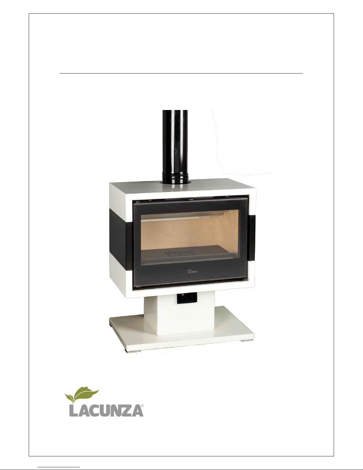
Titanium Plus
Instruction Book
Page 2
PRESENTATION OF THE APPLIANCE 1
1.
Lacunza congratulates you on your choice.
Certified under ISO 9001, Lacunza guarantees the quality of its appliances and undertakes to
meet the needs of its customers.
Confident of the know-how afforded by more than 50 years’ experience, Lacunza uses
advanced technologies in the design and manufacture of its entire range of appliances. This
document will help you install and use your appliance in optimum conditions for your comfort
and safety.
CONTENTS
PRESENTATION OF THE APPLIANCE .................................................................................................... 3
1.1. General characteristics ................................................................................................................................. 3
INSTRUCTIONS FOR THE INSTALLER ................................................................................................... 8
2.1. Warning to installers .................................................................................................................................... 8
2.2. Room for installation.................................................................................................................................... 8
2.2.1. Ventilation of the room ............................................................................................................................................ 8
2.2.2. Location of the appliance in the room ..................................................................................................................... 9
2.3. Installation of the appliance ......................................................................................................................... 9
2.3.1. Floor ......................................................................................................................................................................... 9
2.3.2. Safety distances........................................................................................................................................................ 9
2.3.3. Checks before lighting for the first time ................................................................................................................... 9
2.3.4. Height adjustment and levelling the appliance ........................................................................................................ 9
2.3.5. Connection to the flue.............................................................................................................................................. 9
2.3.6. Piping air to other rooms ......................................................................................................................................... 9
2.3.7. Piping air to the firebox .......................................................................................................................................... 10
2.3.7.1. Combustion-air intake and hot-air output installation options .................................................................................. 11
2.4. Chimney flue .............................................................................................................................................. 14
2.4.1. Type of flue ............................................................................................................................................................ 14
2.4.2. Chimney crown ...................................................................................................................................................... 14
INSTRUCTIONS OF USE ...................................................................................................................... 16
3.1. Fuel............................................................................................................................................................. 16
3.2. Description of the parts of the appliance ................................................................................................... 17
3.2.1. Operating components .......................................................................................................................................... 17
3.3. Lighting ....................................................................................................................................................... 18
3.4. Safety ......................................................................................................................................................... 18
3.5. Loading fuel ................................................................................................................................................ 18
3.6. Operation ................................................................................................................................................... 18
3.7. Removing ash ............................................................................................................................................. 19
3.8. Deflector. ................................................................................................................................................... 19
Page 3

PRESENTATION OF THE APPLIANCE 2
1.
3.9. Electrical system......................................................................................................................................... 20
3.10. Hot-air output control .............................................................................................................................. 21
MAINTENANCE AND IMPORTANT ADVICE ........................................................................................ 22
4.1. Maintenance of the appliance ................................................................................................................... 22
4.1.1. Firebox ................................................................................................................................................................... 22
4.1.2. Flue socket ............................................................................................................................................................. 22
4.1.3. Enamelled-steel parts ............................................................................................................................................. 22
4.1.4. Firebox glass ........................................................................................................................................................... 22
4.1.5. Painted sheet-steel-cast-iron parts. ....................................................................................................................... 22
4.1.6. Electrical system ..................................................................................................................................................... 22
4.1.7. Air intake registers ................................................................................................................................................. 22
4.1.8. leaning the coloured sides...................................................................................................................................... 23
4.2. Maintenance of the chimney flue .............................................................................................................. 23
4.3. Important advice ........................................................................................................................................ 23
TROUBLESHOOTING .......................................................................................................................... 24
BASIC BREAKDOWNS ........................................................................................................................ 25
DECLARATION OF PERFORMANCE .................................................................................................... 28
CE MARK ........................................................................................................................................... 30
Page 4
PRESENTATION OF THE APPLIANCE 3
1.
PRESENTATION OF THE APPLIANCE
For optimum operation of the appliance, we advise you to read this manual carefully before
switching on the appliance for the first time. In case of problems or concerns, we urge you to
contact your dealer, who will cooperate with you.
In order to improve the product, the manufacturer reserves the right to make changes
without notice by updating this document.
This appliance is designed to burn wood in absolutely safe conditions.
WARNING: Faulty installation may have serious consequences.
Installation and all necessary regular maintenance operations must be performed by an
authorized installer in full accordance with the specifications set out in the legislation
applicable in each country and this instruction book.
1.1. General characteristics
Unidad
Titanium
700 Plus
Titanium
701 Plus
Titanium
702 Plus
Titanium
703 Plus
Nominal Heat Output (N.H.O.) to atmosphere
kW
8.5
8.5
8.5
8.5
Efficiency at N.H.O.
%
79
79
79
79
CO emission at 13% O2 at N.H.O.
%
0.10
0.10
0.10
0.10
Gas mass flow at N.H.O.
g/s
10
10
10
10
Gas temperature downstream of flue socket at
ºC
264
264
264
264
Optimum flue draught
Pa
12
12
12
12
Wood consumption (beech) at N.H.O.
kg/h
2.6
2.6
2.6
2.6
Dimensions of the firebox
Width
mm
595
595
595
595
Depth
mm
357
357
357
357
Useful height
mm
203-288
203-288
203-288
203-288
Dimensions of the logs
cm
55
55
55
55
Volume heated (45w/m³) at N.H.O.
m³
189
189
189
189
Log load frequency
h 1 1 1 1
Capacity of the ashpit
L
1,5
1,5
1,5
1,5
Weight
kg
134 (140)
157 (163)
151 (157)
160 (166)
Flue socket diameter
mm
150
150
150
150
Voltage (AC)
V
230
230
230
230
Frequency
Hz
50
50
50
50
Energy efficiency class
- A A A A
Energy efficiency index (EEI)
-
105
105
105
105
Note: The values indicated in the above table are based on tests performed in accordance
with UNE-EN 13240 with logs with no more than 18% humidity and pressure conditions as
indicated in each case.
Page 5
PRESENTATION OF THE APPLIANCE 4
1.
Warning: this appliance is designed and prepared to work with the types of fuel, degree of
humidity of the fuel, fuel loads, fuel load frequencies, flue draught and system of installation
indicated in this Instruction Book. Failure to respect these conditions may lead to problems
with the appliance (deterioration, shorter useful life, etc.) which are not covered by the
Lacunza warranty.
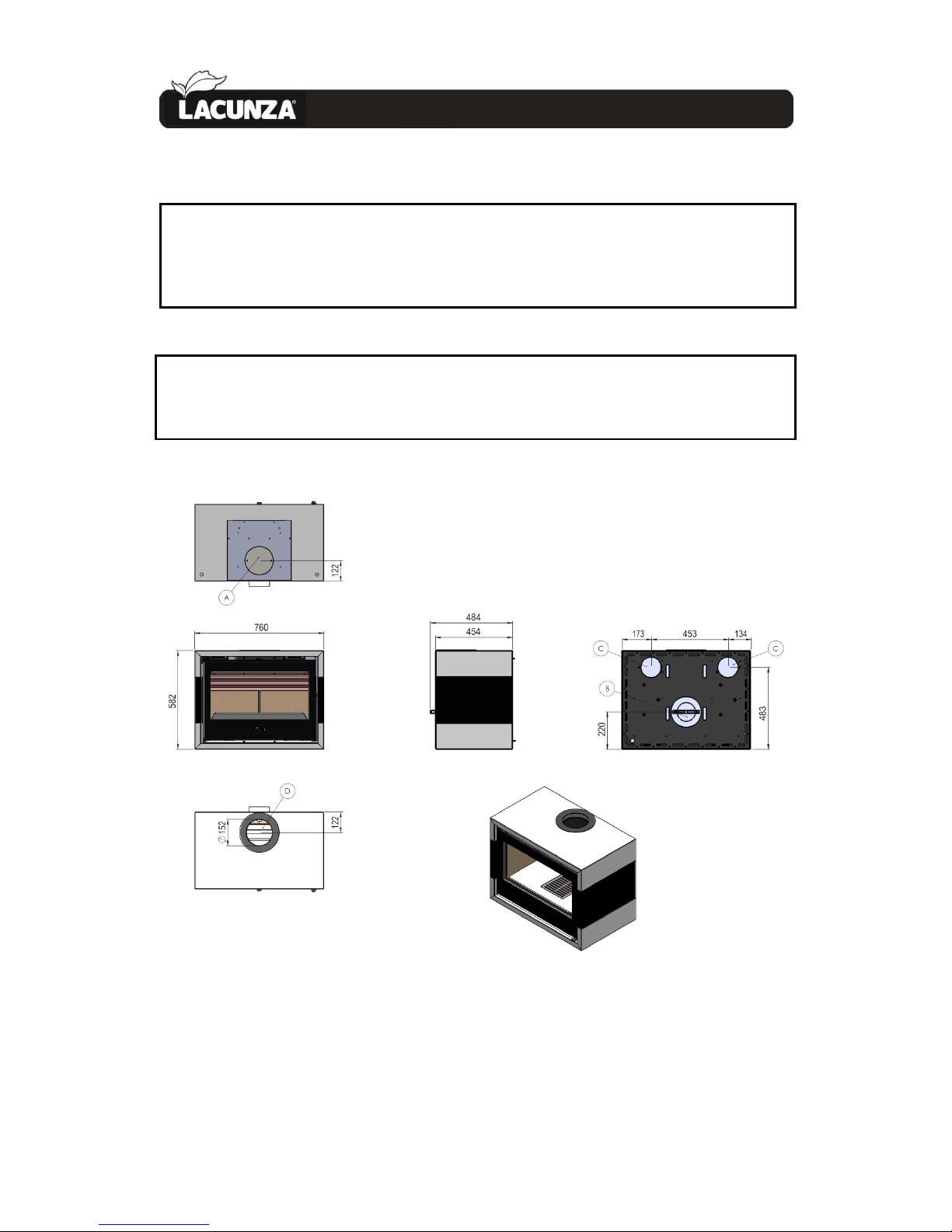
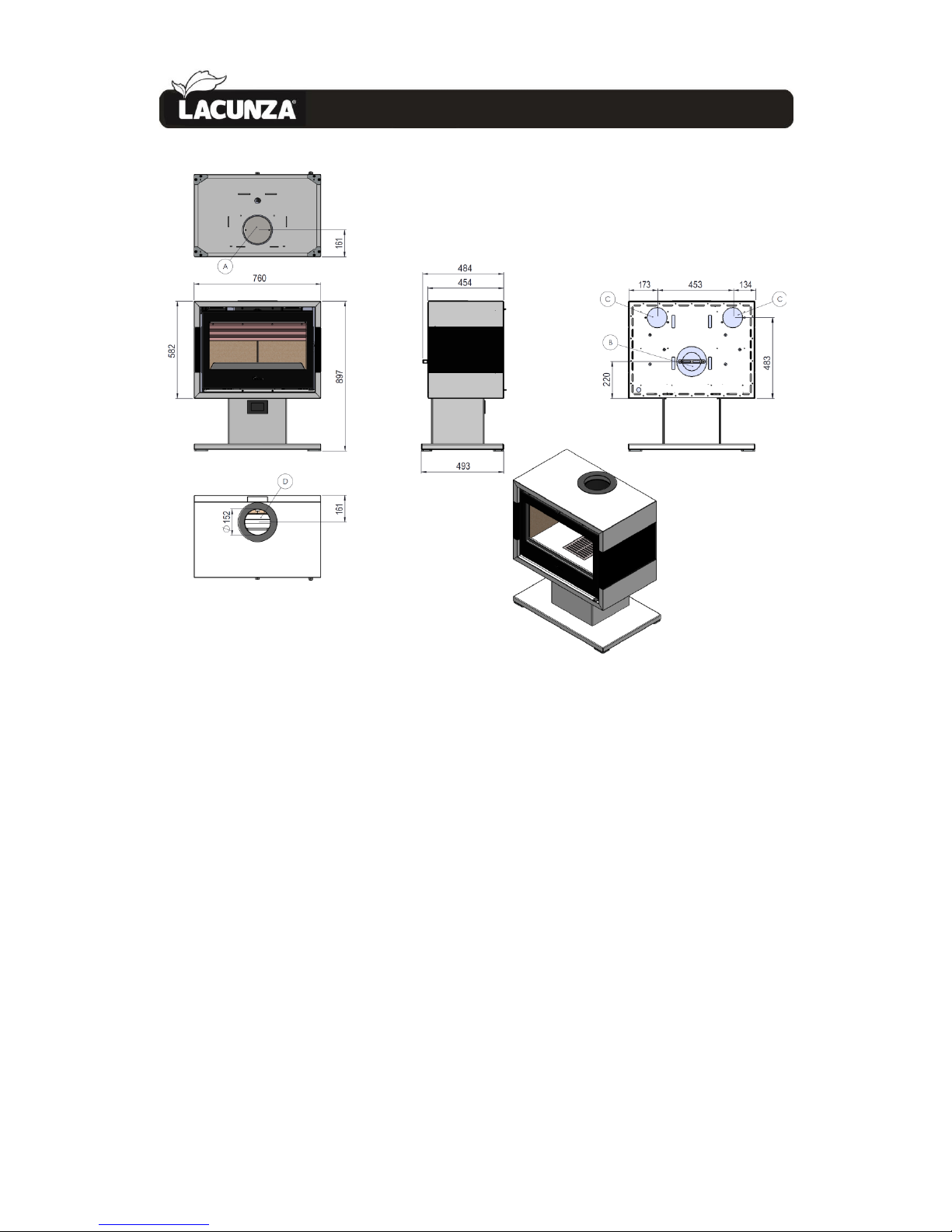
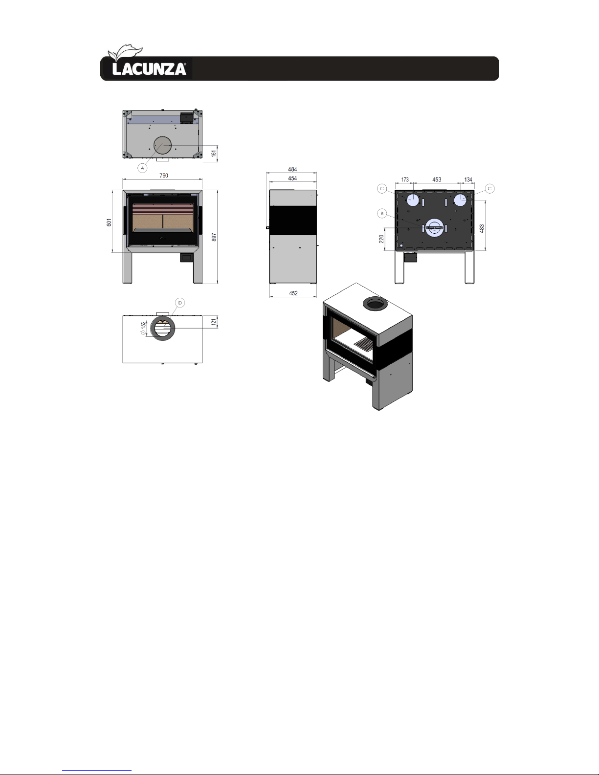
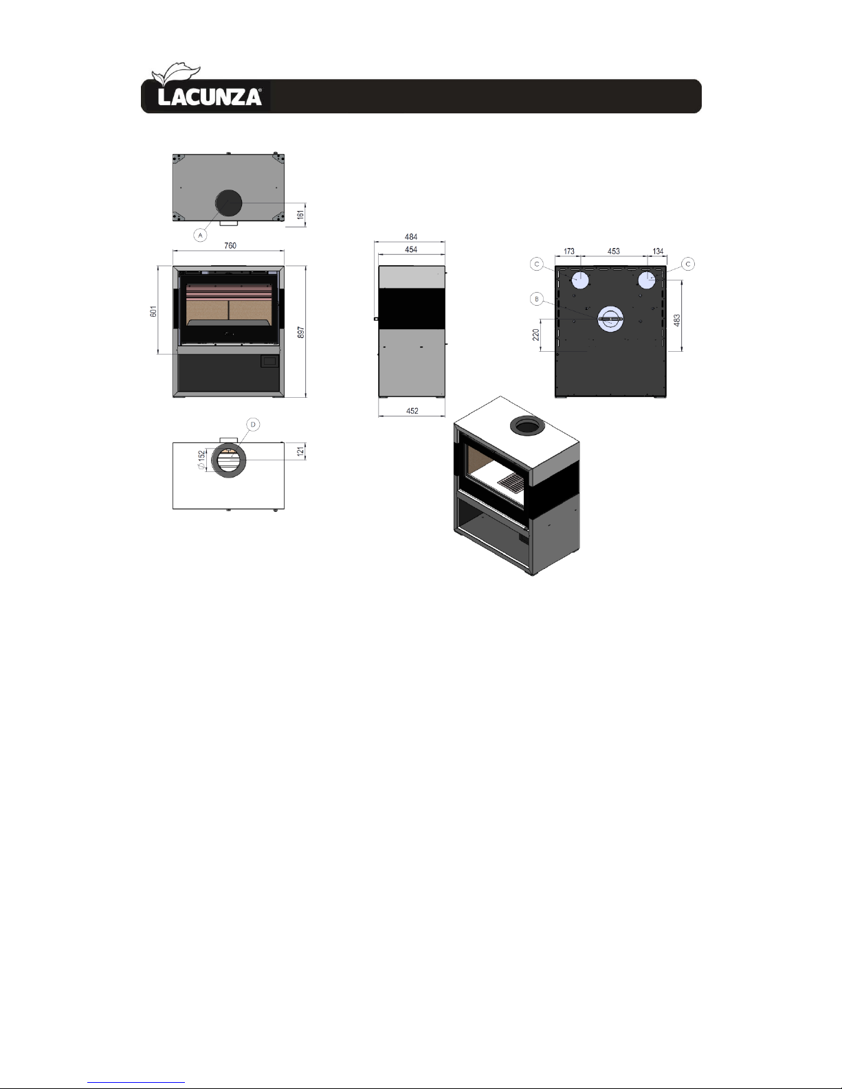
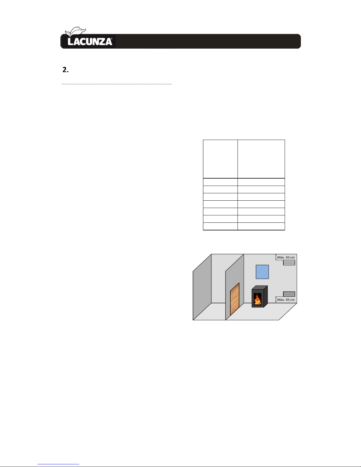
A: lower ductable combustión air intake (Ø120mm)
B: rear ductable combustión air intake (Ø120mm). Factory setting.
C: rear ductable hot air outlets (Ø120mm)
D: top flue socket (Ø150mm)
Figure No.1 - Dimensions of the Titanium 700 Plus appliance in mm
Page 6
PRESENTATION OF THE APPLIANCE 5
1.
Figure No.2 - Dimensions of the Titanium 701 Plus appliance in mm
Page 7
PRESENTATION OF THE APPLIANCE 6
1.
Figure No.3 - Dimensions of the Titanium 702 Plus appliance in mm
Page 8
PRESENTATION OF THE APPLIANCE 7
1.
Figure No.4 - Dimensions of the Titanium 703 Plus appliance in mm
Page 9
INSTRUCTIONS FOR THE INSTALLER 8
2.
INSTRUCTIONS FOR THE
INSTALLER
2.1. Warning to installers
All local and national regulations,
including all those referring to national and
European standards, must be observed
when installing the appliance.
Installation of the appliance must be
performed by an authorised installer.
An incorrectly installed appliance may
lead to serious incidents (fires, creation of
harmful gases, deterioration of nearby
fixtures, etc.).
Lacunza’s liability is limited to the
supply of the material and does not include
installation of the appliance.
2.2. Room for installation
2.2.1. Ventilation of the room
The appliance needs to consume
oxygen (air) in order to work properly.
Ensure a suitable air supply in the room in
which the appliance is fitted. This quantity
of oxygen is additional to the oxygen that
we need in order to breathe (air renewal).
In order to ensure the high quality of
the air you breathe and to avoid potential
accidents resulting from high
concentrations of the gases produced by
combustion (mainly carbon dioxide and
carbon monoxide), it is absolutely crucial to
ensure the suitable renewal of the air in
the room in which the appliance is fitted.
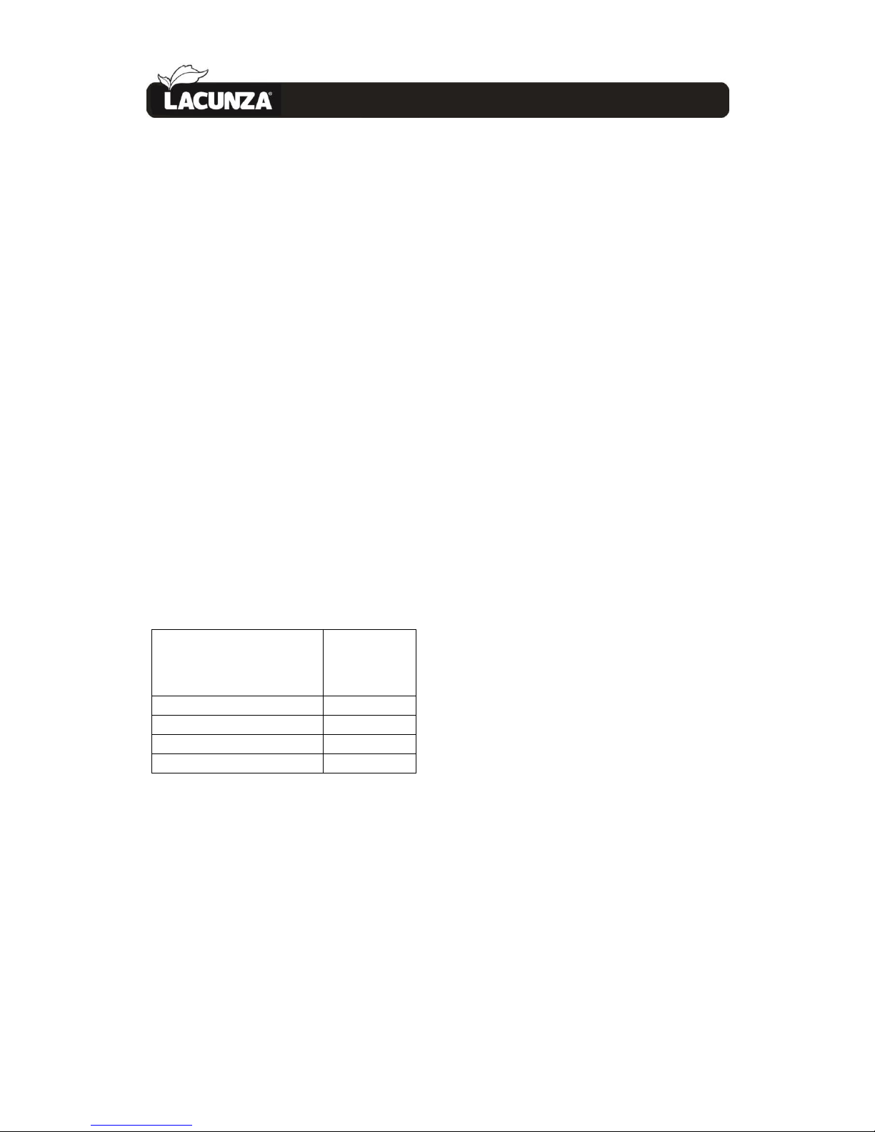
the room must always have at least two
permanent grilles or openings to the
exterior in order to renew the air (one for
intake and the other for extraction).
For the installation of its appliances,
Lacunza recommends an additional section
for these openings. One of these two grilles
must be situated high up in the room (at
less than 30 cm from the ceiling) and the
other one low down (at less than 30 cm
from the floor). Both grilles must open
outdoors in order to renew the air in the
room with fresh air.
The minimum section that each of these
grilles must have depends on the nominal
output of the appliance in accordance with
the following table:
Figure No.5 - Guideline indications for
ventilation grilles
In the case of appliances on which it is
possible to pipe combustion air in from
outdoors, the specifications described in
the Table above are not necessary.
The appliance must always be used with
the door(s) closed.
In rooms equipped with Controlled
Mechanical Ventilation, the system
extracts and renews the ambient air; in
such cases, the room is at slightly low
Output of the
appliance
(kW)
Minimum
additional section
of each of the
grilles (cm2)
P ≤ 10kW 70
10 < P ≤ 15 90
15 < P ≤ 20 120
20 < P ≤ 25 150
25 < P ≤ 30 180
30 < P ≤ 35 210
P > 35 240
Page 10
INSTRUCTIONS FOR THE INSTALLER 9
2.
pressure and it is necessary to install a nonclosable outside-air inlet with a section of
at least 90 cm².
2.2.2. Location of the appliance in the
room
Choose a location in the room which
favours good hot-air distribution by
convection and radiation.
2.3. Installation of the appliance
2.3.1. Floor
Make sure that the base can withstand
the total constructed weight of the
appliance and its casing.
When the floor surface (base) is
combustible, fit suitable insulation.
2.3.2. Safety distances
Be sure to respect the appliance
installation distances from combustible
materials. Looking at the appliance headon:
Distance to
combustible
materials
(mm)
From the right-hand side
350
From the left-hand side
350
From the rear
450
From the front
1500
Bear in mind that it may even be
necessary to protect non-combustible
material in order to prevent breakage,
deformation, etc., as a result of
overheating if the non-combustible
material is not designed to withstand high
temperatures.
2.3.3. Checks before lighting for the first
time
• Make sure that the glass is not
broken or damaged.
• Make sure that the flueway is
not obstructed with packing or
loose parts.
• Make sure that the airtight
joints on the flue circuit are in
perfect condition.
• Make sure that the doors close
properly.
• Make sure that all moving parts
are fitted in place.
• Check that the deflector is fitted
properly.
2.3.4. Height adjustment and levelling the
appliance
The appliance must be perfectly level,
horizontally and vertically, both at the
front and on the sides (use a spirit level).
2.3.5. Connection to the flue
The appliance must be connected to the
chimney flue using special piping designed
to resist the products of combustion (e.g.
stainless steel, enamelled steel, etc.).
To connect the flue to the socket flange,
insert the piping inside the flange and seal
the joint with fire sealant or fire cement to
make it completely airtight.
The installer must ensure that the pipe
connected to the appliance is well secured
and there is no chance of it coming free
from its housing (e.g. as a result of
dilatation due to temperature, etc.).
On this appliance, the flue socket can be
fitted on top of the appliance.
2.3.6. Piping air to other rooms
It is possible to pipe some of the heat
generated to other rooms in the house
using the appliance. This does not mean
that the appliance works more efficiently,
but it does mean that the heat it creates is
distributed better. For this purpose, in the
back surface of the appliance there are 2
potential hot-air outlets with diameters of
Page 11
INSTRUCTIONS FOR THE INSTALLER 10
2.
120mm. Pipes can be fitted from these
outlets to other rooms. If you intend to do
this, bear the following points in mind.
• The air ducts must always be
heat insulated and smooth
inside (not corrugated).
• The pipes must always have an
upward slant to facilitate
movement by air density.
• On routes with a lot of load loss
(a lot of retention), air
movement can be forced along
the ducts using a motor or fan,
provided that it is designed to
withstand such temperature
conditions.
Bear in mind that air ducts mean that
noise travels more easily from one room to
another.
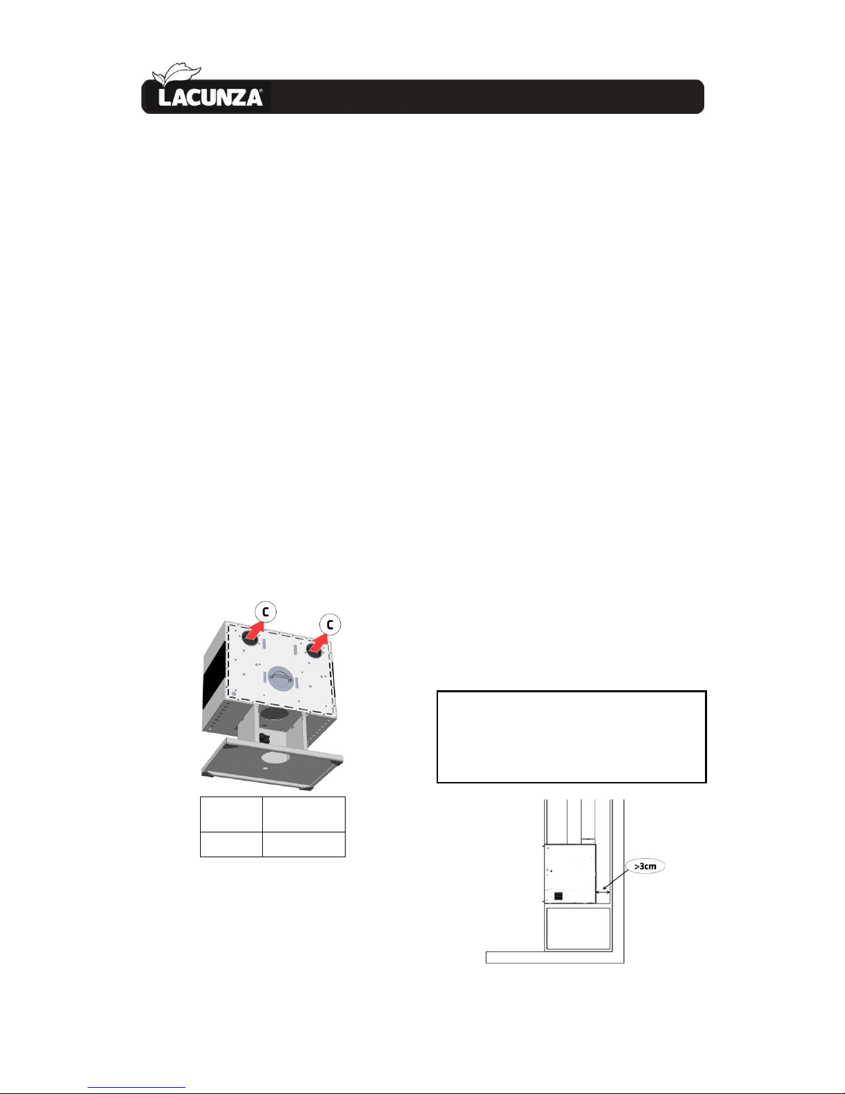
The following table shows the heat
output of the air from the hot-air outlets
with the appliance working at Nominal
Heat Output:
Output
(kW)
C
3.3
Figure No.6 - Table showing heat output of the
air leaving the appliance
Note: The values shown in the above
table were measured at the appliance
output point and based on tests performed
at nominal heat output and maximum fan
speed.
All hot-air ducts lose heat, meaning that
the heat output obtained at the end of
piping always depends on its design.
2.3.7. Piping air to the firebox
On this model, it is possible to pipe air
to the appliance for combustion straight
from outdoors. We recommend that, if
possible, air be drawn from outdoors for
combustion via a non-closable pipe with a
diameter of 120mm leading to the nozzle
on the bottom-front of the appliance. This
is the best option because it means that
draughts are not created in and oxygen is
not consumed from the room in which the
appliance is fitted. A further advantage is
that there is no danger of downdraught
which may hinder the correct updraught of
the appliance when an extractor or
mechanical ventilation appliance is used in
the same room as the central-heating
appliance or in another one alongside it.
If this is not possible, ensure that the
appliance receives air for combustion via
the relevant grille at the bottom of the
hood (in addition to the hood ventilation
grilles).
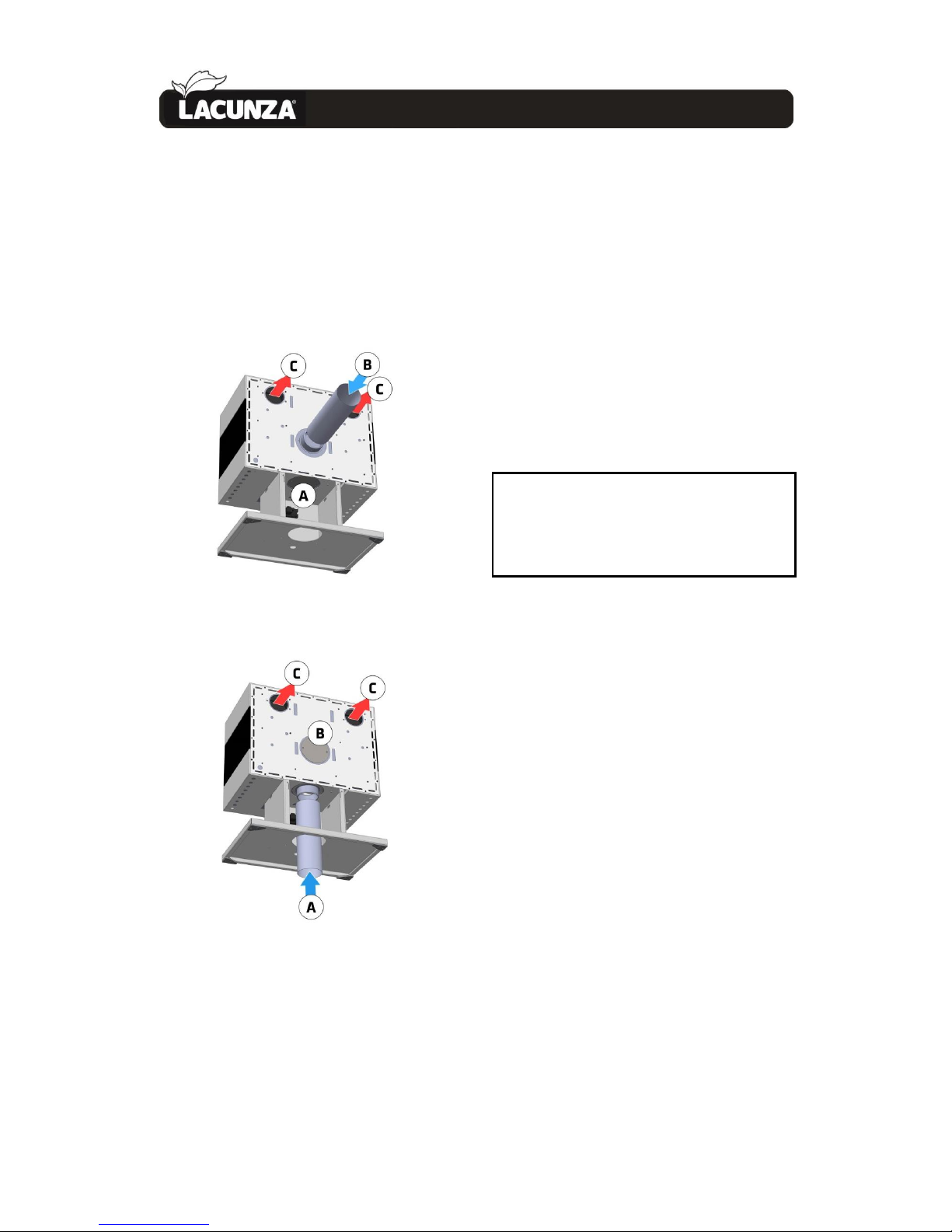
Important: if the appliance is not installed
with piped air input, DO NOT remove the
part at the rear which ensures the right
distance between the rear wall and the
appliance. This must be more than 3 cm
Page 12
INSTRUCTIONS FOR THE INSTALLER 11
2.
Figure No.7 - Separation between the appliance
and the rear wall
If we want to duct the combustion air
intake from the outside, it can be
connected to the rear part of the appliance
(factory setting) or to the lower part of the
appliance.
Figure No.8 - Combustion air intake ducted
from the rear part (B). Lower intake (A) closed.
Figure No.9 - Combustion air intake ducted
from the lower part (A). Rear intake (B) closed.
If we want to duct the combustion air
intake from the lower part, we need to
unscrew the circular cover from the lower
part (A) and screw it in the rear part (B).
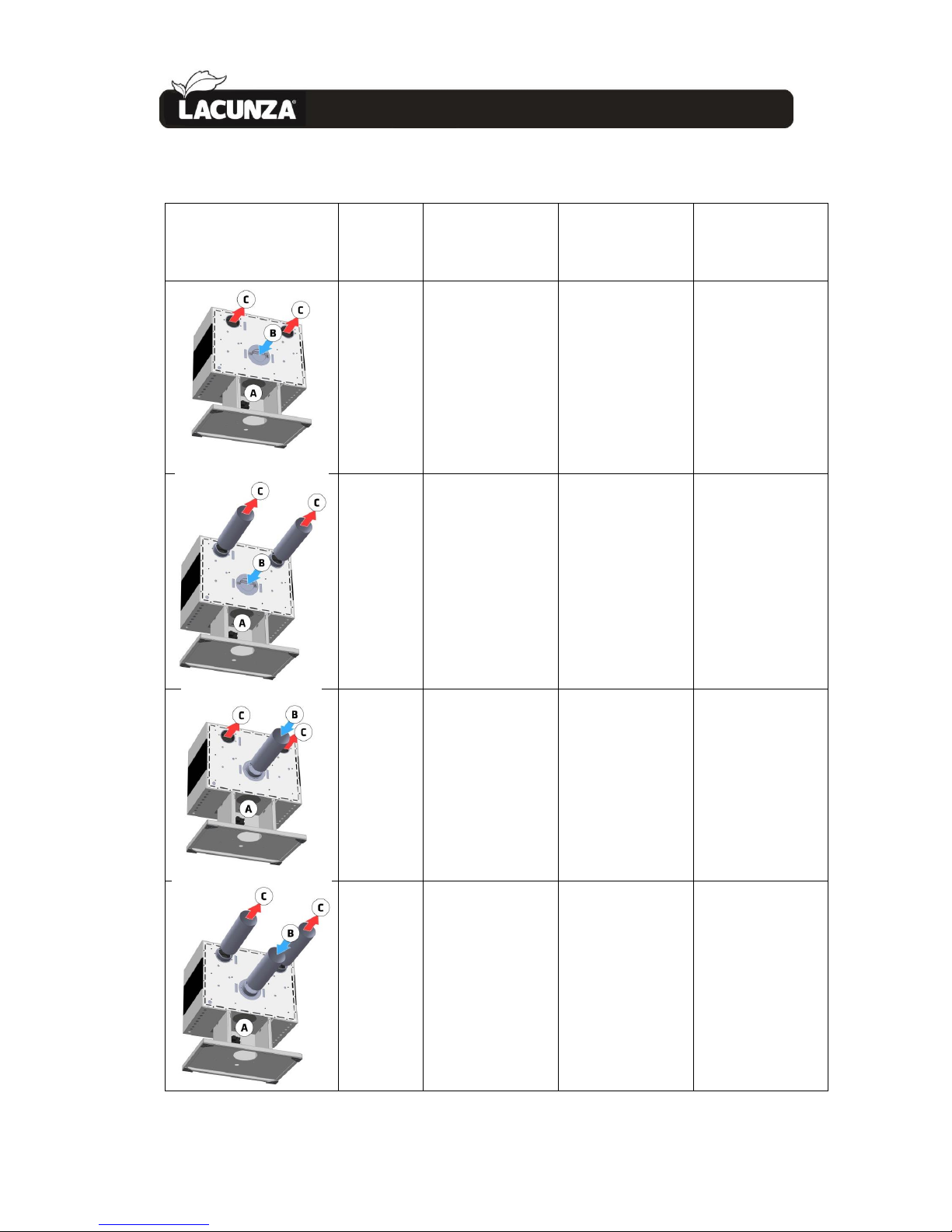
2.3.7.1. Combustion-air intake and hot-air
output installation options
Different installation systems need to
be borne in mind depending on the source
of combustion air (air from outdoors or
from inside the room in which the
appliance is fitted) and the hot-air output
system (air output by natural convection or
by forced convection involving a fan) to
ensure that the appliance works properly.
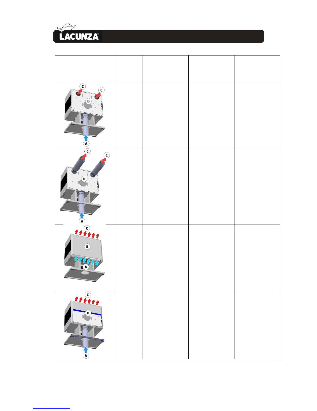
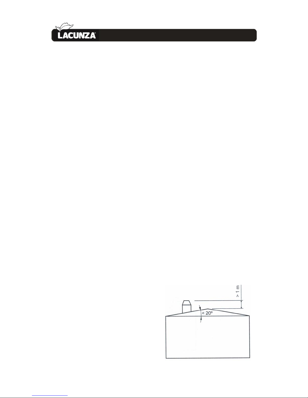
There now follows a description and image
of each of these options:
A: Lower ductable combustion air intake
(Ø120mm)
B: Rear ductable combustion air intake
(Ø120mm)
C: Rear ductable hot air outlets (Ø120mm)
Page 13
INSTRUCTIONS FOR THE INSTALLER 12
2.
Opciones con entrada de aire para combustión trasera
OPTION
Models
A
lower ductable
combustion air intake
B
rear ductable
combustion air intake
C
rear ductable hot air
outlets
(Factory setting)
700
701
702
703
Closed
Open
Open
700
701
702
703
Closed
Open
Ducted
700
701
702
703
Closed
Ducted
Open
700
701
702
703
Closed
Ducted
Ducted
Page 14
INSTRUCTIONS FOR THE INSTALLER 13
2.
OPTION
Models
A
lower ductable
combustion air intake
B
rear ductable
combustion air intake
C
rear ductable hot air
outlets
701
702
703
Ducted
Closed
Open
701
702
703
Ducted
Closed
Ducted
(Factory setting)
700 D/T
701 D/T
702 D/T
703 D/T
Closed
Open
Open
701 D/T
702 D/T
703 D/T
Ducted
Closed
Open
Page 15
INSTRUCTIONS FOR THE INSTALLER 14
2.
2.4. Chimney flue
The chimney flue must comply with
present standards on the installation of
chimneys.
In rooms equipped with Controlled
Mechanical Ventilation, the ventilation
outlet must never be connected to the
flue.
The appliance must always have its own
chimney flue, never sharing a chimney flue
with another appliance.
2.4.1. Type of flue
The flue must be made of special
material designed to resist the products of
combustion (e.g. stainless steel, enamelled
steel, etc.).
Central-heating appliances (with back
boiler) require a double-sleeve flue,
insulated throughout the installation, even
inside the building. This prevents the gases
from cooling down too much and,
consequently, prevents downdraughts,
condensation and low top surface and
oven temperatures on kitchen stoves.
If the chimney is constructed, then it is
necessary to pipe and insulate it to ensure
correct updraught.
The diameter of the pipe must be the
same as the diameter of the flue socket on
the appliance over its entire length in order
to ensure correct operation.
The flue must prevent the entry of
rainwater.
The flue must be clean and airtight over
its entire length.
The flue must be at least 6m tall and the
chimney cap must not hinder the free
release of gases.
If the flue tends to suffer from
downdraught, then it is necessary to fit an
effective anti-downdraught cowl, a static
cowl or a smoke extraction fan, or reshape
the chimney.
Never make 90º bends due to the great
loss of draught they cause, and reduce 45º
bends down to an absolute minimum. Each
45º bend is equivalent to a 0.5m reduction
in flue length. Horizontal flue sections
should not be installed because they cut
updraught a great deal.
If the flue draws at more than 20 Pa on
12Pa appliances, then an effective damper
must be fitted on the flueway. This damper
must be visible and accessible.
The chimney flue must not rest on the
appliance.
Bear in mind that high temperatures
may be reached in the flue, meaning that it
is essential that insulation be enhanced in
sections in which combustible material is
present (wooden beams, furniture, etc.). It
may even be necessary to protect noncombustible material in order to prevent
breakage, deformation, etc., as a result of
overheating if the material is not designed
to withstand high temperatures.
It must be possible to clean the entire
flue, no sections being left inaccessible for
cleaning purposes.
2.4.2. Chimney crown
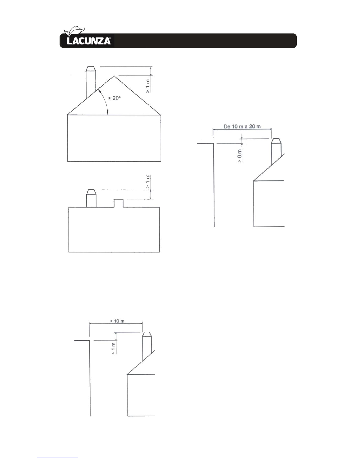
The upper end of the chimney must
clear the roof, the roof ridge or any
obstacle located on the roof by at least 1m.
Page 16
INSTRUCTIONS FOR THE INSTALLER 15
2.
Figure No.10 - Distances between chimney
crown and roof ridge
The chimney crown must clear the
highest point of any neighbouring building
or obstacle located within a 10m radius of
the chimney outlet by more than 1m.
Figure No.11 - Distances between the chimney
crown and objects within a 10m radius
The chimney crown must clear any
neighbouring building or obstacle located
within a radius of 10m to 20m from the
chimney outlet.
Figure No.12 - Distances between the chimney
crown and objects within a radius of between
10 and 20m
Page 17
INSTRUCTIONS OF USE 16
3.
INSTRUCTIONS OF USE
The manufacturer accepts no liability
whatsoever for damage caused to parts as
a result of the improper use of non-
recommended fuels, modifications made
to the appliance or how it is installed.
Only use original replacement parts.
All local and national regulations,
including those referring to national and
European standards, must be observed
when using the appliance.
Heat is diffused by radiation and
convection via the front and exterior of the
appliance.
3.1. Fuel
This appliance must not be used as an
incinerator. Do not use non-recommended
fuels.
• Use dry logs (max. 16%
humidity), cut at least 2 years
ago, clean of resin and stored in
a sheltered, ventilated place.
• Use hard woods with high
calorie values and good ember
production.
• Large logs should be cut to
useable lengths before being
stored. The logs should have a
maximum diameter of 150mm.
• Finely-chopped wood produces
greater heat output, but also
burns more quickly.
Optimum fuels:
• Beech.
Other fuels:
• Oak, chestnut, ash, maple,
birch, elm, etc.
• Pine and eucalyptus logs are
low density and produce very
long flames, and may cause the
parts of the appliance to wear
out more quickly than normal.
• Resinous wood may mean that
the appliance and the flue need
to be cleaned more often.
Non-permitted fuels:
• All types of coal and liquid fuel.
• “Green wood”. Green or damp
wood reduces the performance
of the appliance and leads to
soot and tar build-up on the
inner walls of the flue,
obstructing it.
• “Recovered wood”. The burning
of treated woods (railway
sleepers, telegraph posts,
plywood, fibreboard, pallets,
etc.) quickly blocks the system
(soot and tar build-up), harms
the environment (pollution,
smells) and may lead to
deformation of the firebox due
to overheating.
• All materials which are not
wood (plastic, spray cans, etc.).
Green and reprocessed wood may cause
chimney fires.
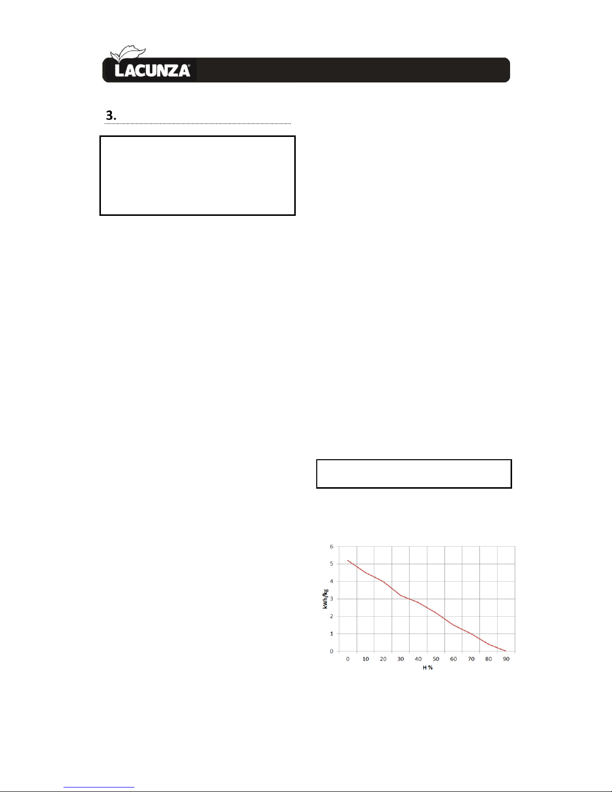
The graph below shows how the
humidity of firewood affects its heat
output:
Figure No.13 - Relationship between firewood
humidity and heat output.
Page 18
INSTRUCTIONS OF USE 17
3.
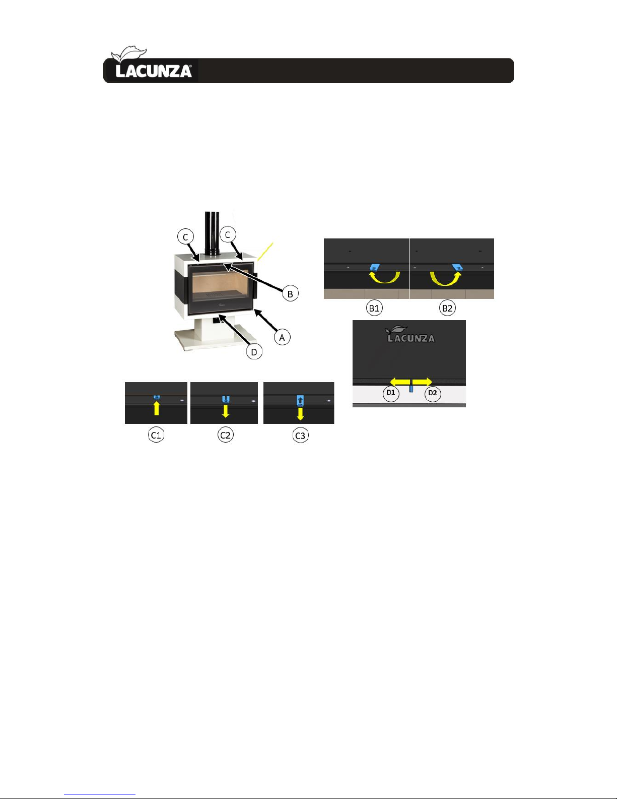
3.2. Description of the parts of the appliance
3.2.1. Operating components
Figure No.14 - Operating components on the appliance
• A: Firebox door handle
• G: Secondary air intake
• C: Hot air selector
o C1 100% air flow to the front
o I2 50% air flow to the front 50% air flow to the nozzle
o C3 100% air flow to the nozzle
• D: Primary air intake
o D1 open (right)
o D2 closed (left)
Page 19
INSTRUCTIONS OF USE 18
3.
3.3. Lighting
Use of the appliance in warm weather
(warm days, early hours of the afternoon
on sunny days) may lead to lighting and
updraught problems.
Certain weather conditions, such as fog,
ice, humidity entering the flue, etc., may
hinder sufficient updraught in the flue and
lead to suffocation.
Proceed as follows in order to light the
appliance satisfactorily:
• Open the firebox door(s) and
open all the firebox air-intake
inlets to the full.
• Place paper or a firelighter and
some wood chips in the firebox.
• Light the paper or firelighter.
• Leave the door slightly ajar, the
width of two or three fingers,
for about 15 minutes until the
glass warms up.
• The first time the appliance is
lit, the fire should be gentle to
allow the parts of the appliance
to dilate and dry.
Important: The first time it is lit up, the
appliance may give off smoke and strange
smells. This is not a cause for concern.
Open an outdoor window to ventilate the
room during the first few hours of
operation.
If you notice water around the
appliance, this is produced by the
condensation of the moisture in the wood
on lighting the fire. This condensation will
no longer appear when the appliance has
been lit three or four times and has
adapted to its flue. If it does not disappear,
then check the flue draught (length and
diameter of the flue, flue insulation,
airtightness) and the humidity of the wood
used.
3.4. Safety
Do not store combustible materials
beneath the appliance.
3.5. Loading fuel
In order to load firewood, open the
firebox door gently, preventing the sudden
entry of air to the firebox so that smoke
does not enter the room that the appliance
is installed in. Perform this operation with
the glove to prevent burns to the hands.
The maximum load height is 2 logs with
diameters of approx. 10 cm.
The minimum interval between loads
for nominal heat output is 60 minutes.
Always load with the nominal amount
(see table in section 1.1).
For minimum burning (e.g. at night), use
thicker logs.
When the firebox is loaded, close the
door.
Be careful when placing logs in the firebox
on appliances with vermiculite interiors.
Vermiculite is a fragile material and may
crack if knocked.
3.6. Operation
The appliance should be operated with
the door closed.
For safety reasons, never close all the
appliance’s combustion-air intakes.
Primary-air intake
By opening this inlet, air enters the
firebox via the firebox grille.
Page 20
INSTRUCTIONS OF USE 19
3.
Secondary-air intake
By opening this inlet, air enters the
firebox via the top of the firebox door.
IMPORTANT: Keeping the secondary-air
intake open helps keep the door glass
cleaner for longer.
Double-combustion air intake
By opening this inlet, air enters the
combustion flame, making for more
efficient and less polluting combustion
because post-combustion takes place,
burning the particles which were not
burned in the first combustion. This
increases the performance of the appliance
and reduces emissions.
In order to obtain maximum output,
open all the air intakes to the firebox and
in order to obtain minimum output, tend
towards closing them. For normal use, we
recommend Secondary Intakes open.
IMPORTANT: The appliance is exposed to
extreme changes in temperature and may,
as a result, make noises when in operation.
These noises are a natural result of
expansion/contraction of the parts which
make up the appliance. Do not be alarmed
by noises of this kind.
In order to obtain maximum output,
open all the air intakes to the firebox and
in order to obtain minimum output, tend
towards closing them. For normal use, we
recommend you close the Primary Intake
and leave the Secondary Combustion
Intakes open.
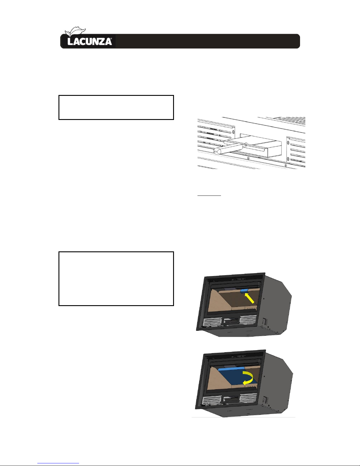
3.7. Removing ash
Following sustained use of the
appliance, it is necessary to remove the ash
from the firebox. Remove the ashpit box
when cold or using something to prevent
yourself from getting burned (glove).
Never throw hot embers into the
rubbish.
Access the ashpit by opening the door
on the appliance.
Figure No.15 - Extract ashpit
Warning! It is very important to put the
ashpit back in its housing at the bottom of
the firebox after emptying it of ashes and
before lighting the fire again! Do this by
following the extraction process in reverse
order.
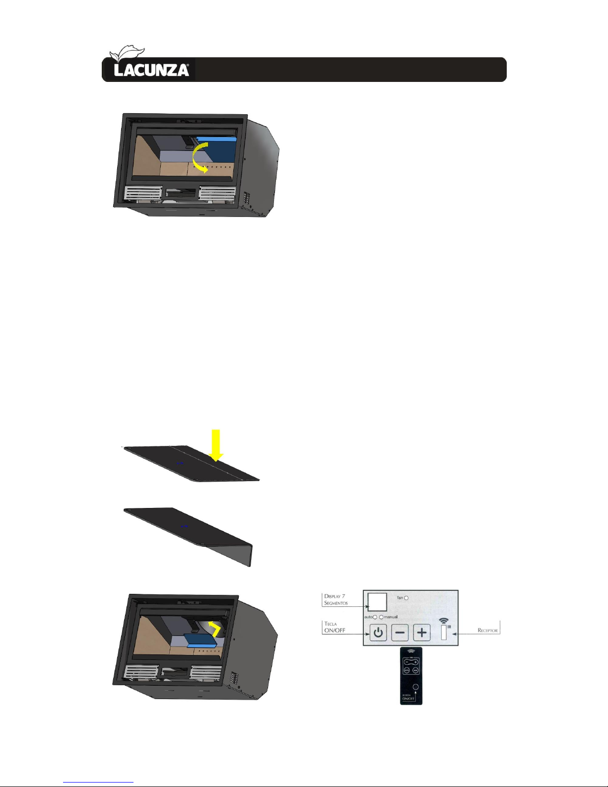
3.8. Deflector.
The appliance has 2 deflectors.
Page 21
INSTRUCTIONS OF USE 20
3.
Figure No.1 - Dismantling the Silver Plus
deflector
Fitting the part on the flue socket
A circular part is supplied inside the
appliance. This part must be fitted in
position inside the flue in order to achieve
all the values in the UNE-EN 13229,
standard. Because this part causes a lot of
the gases produced by combustion to be
retained, it requires optimum flue and fuel
conditions. Users may, therefore, prefer
not to fit it if such conditions cannot be
ensured.
3.9. Electrical system
Forced convetion. Fans
Titanium models have 2 fans for the
forced convection of the hot air generated
around the appliance inside the shell. This
air can be piped to other rooms.
IMPORTANT: This appliance is not
covered by our warranty unless directly
connected to the mains electricity supply in
accordance with the conditions described
in the relevant section in 1.1.
Potentiometer operation:
By means of its rotating lever, the
potentiometer controls the flow of hot-air
output from the appliance in two ways:
• Automatic mode:
The fan automatically starts working at
the set speed via the thermostat. When a
fire has been lit in the firebox and the
thermostat reaches a temperature of
approximately 50ºC, the fan starts working
at the power set on the potentiometer
(rotating wheel) and stops automatically
when the temperature drops beneath
50ºC.
• Manual mode:
The fan works at the speed set using the
rotating wheel independently of the
thermostat, i.e. the fan can be started up
before the thermostat reaches 50ºC.
Figure No.2 - Titanium potentiometer display
Page 22
INSTRUCTIONS OF USE 21
3.
For more information see the
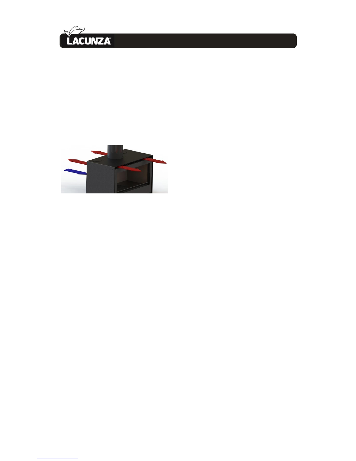
potentiometer instruction manual.
3.10. Hot-air output control
This appliance has a control with which
to choose where and how much hot air
should be released through the front of the
appliance and the nozzle.
Figure No.3 - The flow through each output is
regulated by moving the control.
Page 23
MAINTENANCE AND IMPORTANT ADVICE 22
4.
MAINTENANCE AND
IMPORTANT ADVICE
4.1. Maintenance of the appliance
The appliance, the flue connector piping
and the flue must be cleaned regularly,
particularly following long periods without
use.
4.1.1. Firebox
Clean the firebox area of ash, etc.
On central-heating appliances, clean the
walls of soot (creosote) in order to
enhance performance and allow the
firebox grille to rise and lower properly.
4.1.2. Flue socket
The flue socket area must be kept clean
at all times for the appliance to work
properly.
It must be cleaned as often as required.
How often it is cleaned depends on how
much the appliance is used and the type of
fuel employed.
4.1.3. Enamelled-steel parts
Use a damp cloth with neutral soap to
clean the enamelled-steel parts and dry
immediately. Do not use abrasive,
corrosive, chlorine-based or acid-based
products to clean the enamelled-steel
parts; they could damage the enamel.
4.1.4. Firebox glass
Keep the secondary-air intake open to
keep the door glass cleaner for longer.
However, the glass may get dirty the longer
the appliance is used. Special degreasing
products designed for the purpose should
be used to clean it.
Clean when the glass is cold and taking
care not to apply the glass cleaner directly
onto the glass as it could come into contact
with the door-seal cord and damage it.
4.1.5. Painted sheet-steel-cast-iron parts.
These parts should be cleaned with a
brush or dry cloth. Do not dampen the
parts: the steel could rust and the paint
could blister and chip. Be particularly
careful when cleaning the glass: the liquids
used must not dampen the painted steel.
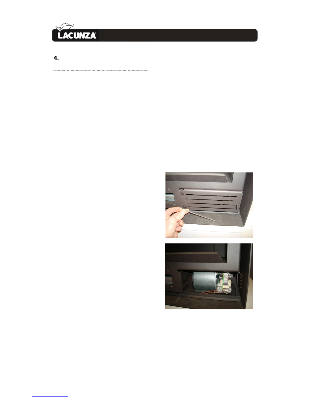
4.1.6. Electrical system
The electrical system should be
cleaned-vacuumed regularly (depending on
the installation and use), so as to avoid the
accumulation of ash, lint and other remains
that may generate strange noises and/or
deteriorate the ventilators and electrical
system. Disconnect the electrical network
system to perform this task.
Figure No.4 - Electrical system
4.1.7. Air intake registers
In the air intake for combustion
registers, remains of ash, sawdust, cleaning
fluids, etc. may accumulate, which restrict
Page 24
MAINTENANCE AND IMPORTANT ADVICE 23
4.
or hinder its movement. In these cases,
they should be released and cleaned.
4.1.8. leaning the coloured sides
To clean the coloured sides, use a damp
cloth, neutral soap and dry immediately
after. Do not use scouring pads or abrasive,
stripping or acid-based products as they
may damage the surface.
4.2. Maintenance of the chimney
flue
VERY IMPORTANT: In order to avoid
incidents (chimney fires, etc.), it is
necessary to perform maintenance and
cleaning operations on a regular basis; if
the appliance is used often, then the
chimney and the flue connector piping
must be swept several times a year.
In the event of fire in the chimney, close
the flue draught, close doors and windows,
remove embers from the firebox, block the
connection hole with damp cloths and call
the fire brigade.
4.3. Important advice
Lacunza recommends that only
Lacunza-authorised replacement parts be
used.
Lacunza accepts no liability for any
modification to the product which it has
not authorised.
This appliance is a heat-producing
appliance and contact may lead to burns.
This appliance may remain HOT for a
period of time after it has gone out. MAKE
SURE THAT SMALL CHILDREN DO NOT GO
NEAR IT.
Page 25
TROUBLESHOOTING 24
5.
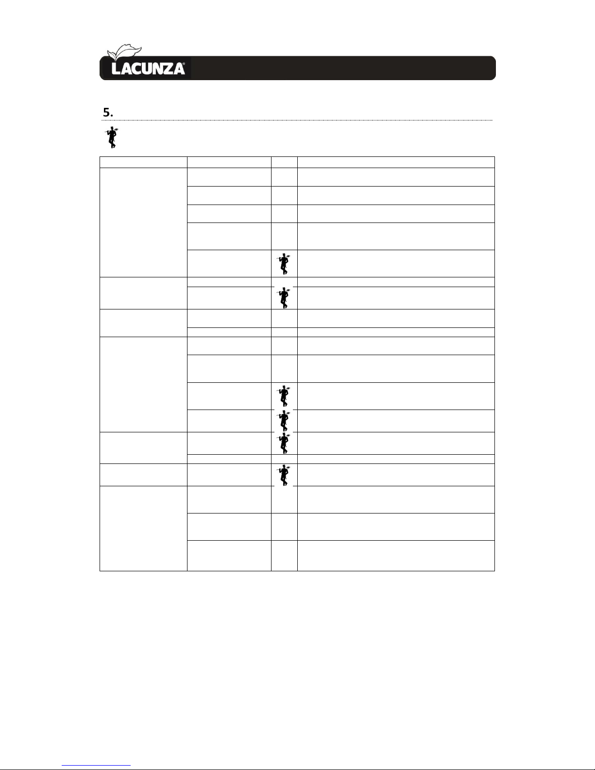
TROUBLESHOOTING
This symbol means that a qualified professional should be called to perform the operation.
Problem
Probable causes
Solution
The fire does not light
properly
The fire does not stay
alight
Green or damp wood
Use hard woods, cut at least 2 years ago and stored in a
sheltered, ventilated place
The logs are too large
Use crumpled paper or firelighters and dry wood chips to light
the fire. Use split logs to keep the fire going
Poor-quality wood
Use hard woods which produce heat and embers (chestnut, ash,
maple, birch, elm, beech, etc.)
Insufficient primary air
Open the primary- and secondary-air intakes completely, or
even open the door slightly.
Open the outdoor-air inlet grille
Insufficient updraught
Check that the draught is not blocked. De-soot if necessary.
Check that the flue is in perfect condition (airtight, insulated,
dry, etc.)
The fire flames up too
much
Excessive primary air
Close the primary- and secondary-air intakes partially or totally
Excessive updraught
Install a draught damper
Smoke given off on
lighting
Poor-quality wood
Do not continually burn chips, carpentry scraps (plywood,
pallets, etc.)
Cold flue
Heat up the flue by burning a piece of paper in the firebox.
Smoke during burning
The room is at low
pressure
In rooms with Controlled Mechanical Ventilation, leave an
outdoor window ajar until the fire is fully alight.
Too little wood loaded
Load as recommended. Loads notably smaller than those
recommended lead to low smoke temperature and
downdraught.
Insufficient updraught
Check the condition of the flue and insulation.
Check that the piping is not blocked. Clean mechanically if
necessary
Wind enters the flue
Install an anti-downdraught system (Cowl) at the top of the
chimney
Does not warm up enough
The room is at low
pressure
In rooms with Controlled Mechanical Ventilation, there must be
an outdoor-air inlet
Poor-quality wood
Only use the recommended fuel
The fans do not work
Electrical fault
Water condenses (after
the appliance has been lit
more than 3 or 4 times)
Too little wood loaded
Load as recommended. Loads notably smaller than those
recommended lead to low smoke temperature and
condensation.
Green or damp wood
Use hard woods, cut at least 2 years ago and stored in a
sheltered, ventilated place.
Condition of the flue
Lengthen the flue (5-6 metres minimum). Insulate the flue
properly. Check the airtightness of the flue/appliance.
Page 26
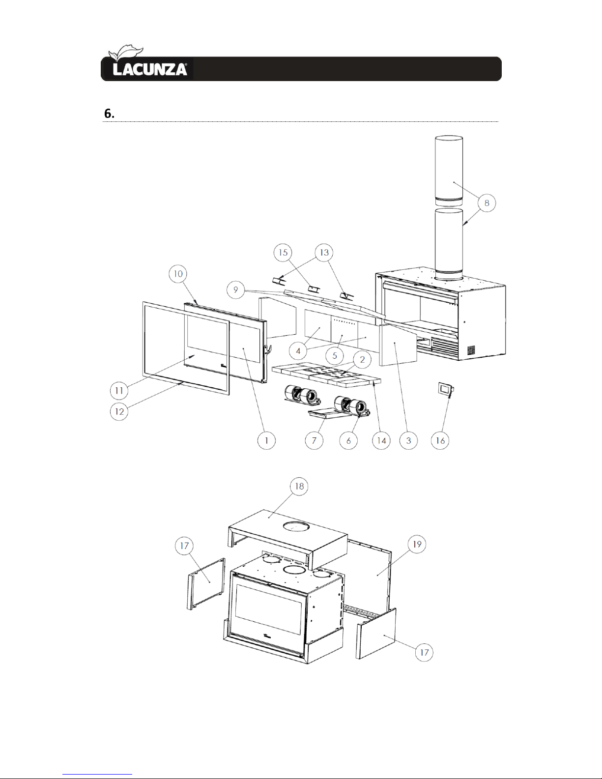
BASIC BREAKDOWNS 25
6.
BASIC BREAKDOWNS
Page 27
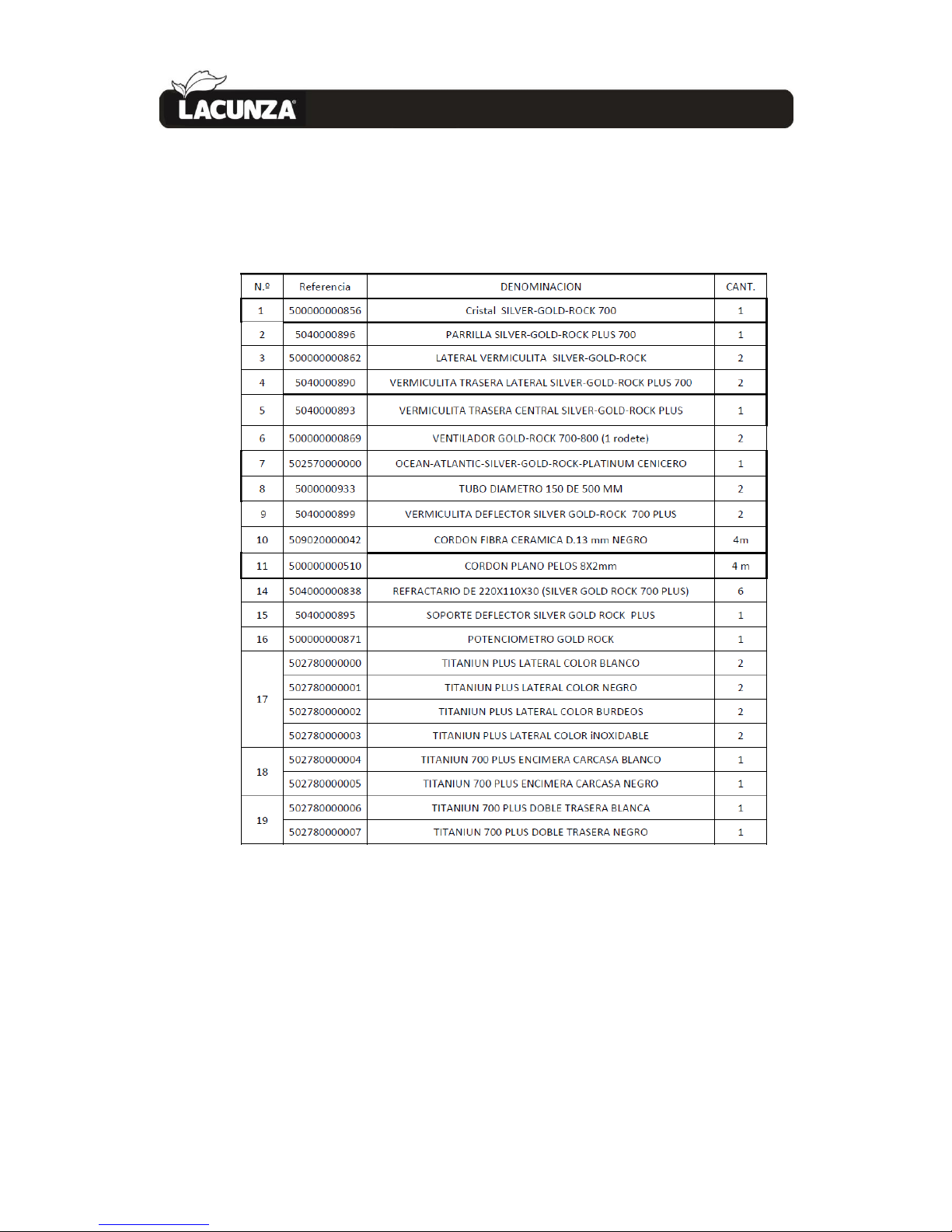
BASIC BREAKDOWNS 26
6.
Page 28
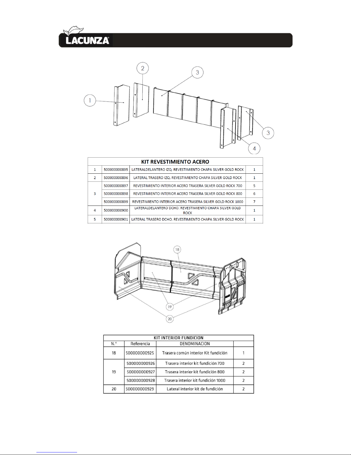
BASIC BREAKDOWNS 27
6.
Page 29
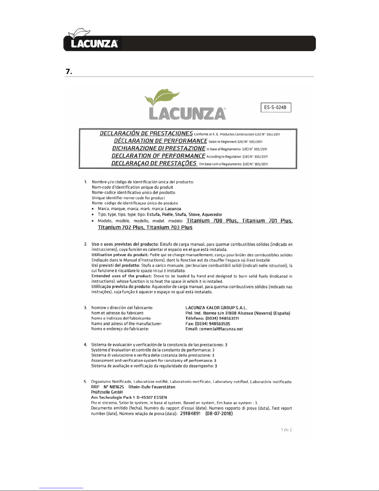
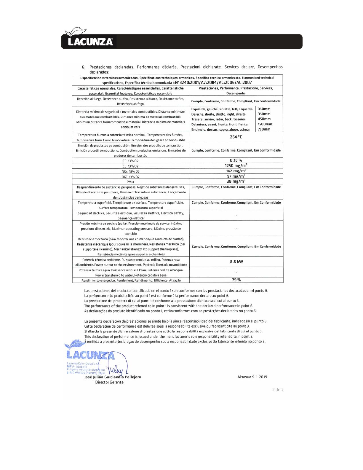
DECLARATION OF PERFORMANCE 28
7.
DECLARATION OF PERFORMANCE
Page 30
DECLARATION OF PERFORMANCE 29
7.
Page 31
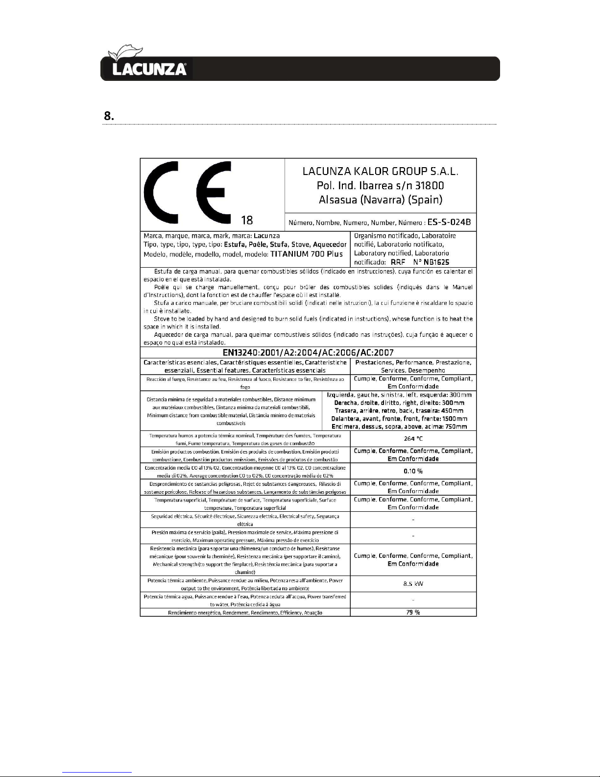
CE MARK 30
8.
CE MARK
Page 32

LACUNZA KALOR GROUP S.A.L
Pol. Ind. Ibarrea s/n
31800 Alsasua (Navarra) Spain
Tel.: (00 34) 948 56 35 11
Fax.: (00 34) 948 56 35 05
e-mail: [email protected]
Website: www.lacunza.net
EDITION: 00
 Loading...