

Page 1

Contents
Language Page
_________________________________________________________________________________
English 1
French 56
Spanish
1
Page 2

TABLE OF CONTENTS
Topic
Inventory of Contents
Features
Setting Up
Battery Installation
Function keys
LCD Screen and Settings
Atomic time - WWVB Radio Controlled Time 20
Manual Settings 21
Weather Forecast and Tendency 31
Display of Indoor Temperature and Humidity Reading 37
Display of Outdoor Temperature and Humidity Reading 38
Page
4
5
8
12
15
17
2
Page 3
Display of Indoor Minimum and Maximum records 39
Display of Outdoor Minimum and Maximum records 40
Daily Min and Max outdoor temperature display 43
915 MHz Reception 44
Mounting 45
Care and maintenance 50
Specifications 51
Warranty 53
3
Page 4
This product offers:
INSTANT TRANSMISSION is the state-of-the-art
new wireless transmission technology, exclusively
designed and developed by LA CROSSE
TECHNOLOGY. INSTANT TRANSMISSION offers
you an immediate update (every 4 seconds!) of all
your outdoor data measured from the sensors:
follow your climatic variations in real-time!
4
Page 5

INVENTORY OF CONTENTS
1.
Wireless Weather Station
2.
Wireless Thermo-hygro Sensor (TX29UTH-IT) and mounting bracket.
3.
Instruction Manual and Warranty Card.
4.
4 Fresh “AA” IEC LR6, 1.5V Alkaline Batteries.
5
Page 6
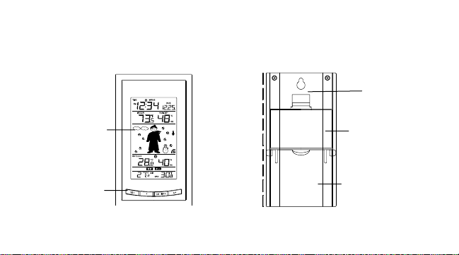
FEATURES:
The Weather Station
LCD
Display
Function
Keys
Hanging hole
Battery
compartment
cover
Foldout
Stand
6
Page 7

•
Atomic auto-set time (WWVB Radio controlled time) or manual time setting options
•
Atomic auto-set time reception ON/OFF setting
•
12/24 hour display
•
Daylight time saving ON/OFF
•
Hour, minute and second display
•
Time zone option ±12 hours
•
Wireless transmission at 915 MHz
•
Signal reception intervals at 4-second
•
Display indoor and outdoor temperature in (°F) or (°C) and indoor and outdoor humidity
(% RH)
Weather forecasting with 15 easy-to-read weather forecast signs featuring Oscar Outlook
Forecaster
•
Weather forecasting icon sensitivity setting
•
Temperature display in degrees Fahrenheit (°F) or Celsius (°C) selectable
7
Page 8

•
Indoor and Outdoor temperature and humidity display with MIN/MAX recording
•
All MIN/MAX outdoor recordings show date and time received and all MIN/MAX recordings
can be reset
•
Daily Outdoor minimum and maximum temperature display
•
Can receive up to three sensors
•
LCD contrast setting
•
Low battery indicator
•
Table standing/ Wall mounting
8
Page 9
The Outdoor Thermo-hygro Sensor
•
Remote transmission of outdoor temperature and humidity to
Weather Station by 915 MHz
•
Shower proof casing
•
Wall mounting case
•
Mounting at a sheltered place. Avoid direct rain and sunshine
9
Page 10

SETTING UP:
When one sensor is to be used
1. First, insert the batteries into the thermo-hygro sensor. (see “Install and replace
batteries in the thermo-hygro sensor “).
2. Immediately after and within 30 seconds, insert the batteries into Weather Station (see
“Install and replace batteries in the Weather Station”). Once the batteries are in place,
all segments of the LCD will light up briefly. Following the time as 12:00 and the "Oscar
Outlook" icon will be displayed. If these are not displayed after 60 seconds, remove the
batteries and wait for at least 10 seconds before reinserting them.
3. After inserting the batteries into the sensor, the Weather Station will start receiving data
from the sensor. The outdoor temperature and humidity and the signal reception icon
should then be displayed on the Weather Station. If this does not happen after 3 minutes,
the batteries will need to be removed from both units and reset from step 1.
10
Page 11

4. In order to ensure sufficient 915 MHz transmission however, this should under good
conditions be a distance no more than 100 meters between the final position of the
Weather Station and the sensor (see notes on “Mounting” and “915 MHz Reception”).
When more than one sensor is to be used
1. User shall remove all the batteries from the Weather Station and sensors and wait 60
seconds if setting has been done with one sensor before.
2. Insert the batteries to the first sensor.
3. Within 30 seconds of powering up the first sensor, insert the batteries to the Weather
Station. Once the batteries are in place, all segments of the LCD will light up briefly.
Following time as 12:00 and the Oscar Outlook icon will be displayed. If they are not shown
in LCD after 60 seconds, remove the batteries and wait for at least 60 secon ds before
reinserting them.
4. The outdoor temperature and humidity from the first sensor (channel 1) should then be
11
Page 12

displayed on the Weather Station. Also, the signal reception icon will be displayed. If this
does not happen after 2 minutes, the batteries will need to be removed from both units and
reset from step 1.
5. Insert the batteries to the second sensor as soon as the outdoor temperature readings from
the first sensor are displayed on the Weather Station.
Note: User shall insert the batteries into the second sensor within 30 seconds of reception of the
first .
6. The outdoor temperature and humidity from the second sensor and the "channel 2" icon
should then be displayed on the Weather Station. If this does not happen after 2 minute,
the batteries will need to be removed from all the units and reset from step 1.
7. Insert the batteries to the third sensor as soon as the "channel 2" icon and outdoor data are
displayed on the Weather Station. Then within 2 minutes, the channel 3 outdoor data from
the third sensor will be displayed and the channel icon will shift back to "1" once the third
12
Page 13

sensor is successfully received. If this is not happen, user shall restart the setting up from
step 1.
User shall insert the batteries into the third sensor within 30 seconds of reception of the
Note:
second sensor.
8. In order to ensure sufficient 915 MHz transmission there should be no more than 330 feet
(100 meters) between the final position of the Weather Station and the sensor (see notes
on “Mounting” and “915 MHz Reception”).
Note:
If the signal reception is not successful on the first frequency (915MHz) for 45 seconds, the
frequency is changed to 920MHz and the learning is tried another 45 seconds. If still not
successful the reception is tried for 45 seconds on 910MHz. This will also be done for resynchronization.
13
Page 14

IMPORTANT:
Transmission problems will arise if the setting for additional sensors is not followed as described
above. Should transmission problems occur, it is necessary to remove the b atteries from all units
and start again the set-up from step 1.
9. Once the remote temperature has been received and displayed on the Weather Station, the
Atomic time (WWVB time) code reception is automatically started. This takes typically
between 3-5 minutes in good conditions.
Note:
•
If after 10 minutes, the Atomic Time (WWVB) time has not been received, press the SET
key to manually enter a time initially.
•
Daily WWVB reception (Atomic time) is attempted at full hour between 12:00 am to 6:00
am. If the reception is successful, there will no reception attempt until the following day.
When this is successful, the received time will override the manually set time. The date is
14
Page 15
also updated with the received time. (Please refer also to notes on “Atomic time WWVB Radio controlled Time” and “Manual Time Setting”)
BATTERY INSTALLATION
INSTALL AND REPLACE BATTERIES IN THE WEATHER STATION
The Weather Station uses 2 x AA, IEC LR6, 1.5V batteries. To install and replace the batteries,
please follow the steps below:
1. Remove the cover at the back of the Weather Station.
2. Insert batteries observing the correct polarity (see
marking).
3. Replace compartment cover.
15
Page 16
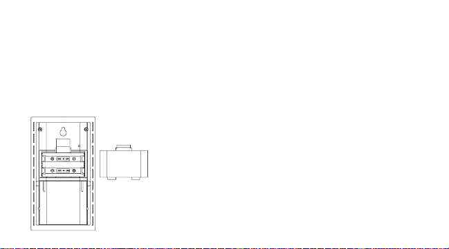
INSTALL AND REPLACE BATTERIES IN THE
The sensor uses 2 x AA, IEC LR6, 1.5V Alkaline batteries. To install and replace the batteries,
please follow the steps below:
1. Pull out the battery holder at the bottom of the sensor.
2. Insert the batteries, observing the correct polarity (see marking).
3. Replace the battery holder on the unit.
THERMO-HYGRO SENSOR
16
Page 17

Note:
In the event of changing batteries in any of the units, all units need to be reset by following the
setting up procedures. This is because a random security code is assigned by the sensor at startup and this code must be received and stored by the Weather Station in the first 3 minutes of
power being supplied to it
BATTERY CHANGE:
It is recommended to replace the batteries in all units regularly to ensure optimum accuracy of
these units (Battery life See Specifications below).
Please participate in the preservation of the environment. Return used batteries
to an authorized depot.
17
Page 18
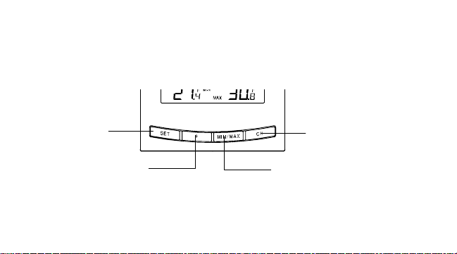
FUNCTION KEYS:
Weather Station:
The Weather Station has four easy to use function keys.
SET key
+ key
18
MIN/
MAX key
CH key
Page 19

SET key (Setting):
•
To enter the set mode for the following functions: LCD contrast, Time zone, Daylight saving
time ON/ OFF, Time Reception ON/OFF, 12/24 hour display, Manual time, Year, Month,
Day, °F/°C, and Weather Forecast sensitivity settings.
•
Press to reset the minimum or maximum temperature and humidity records of the indoor or
the currently selected outdoor channel (will reset all records to current le vel)
MIN/ MAX
•
To toggle between the minimum/maximum outdoor temperature and minimum/maximum
indoor temperature data
+ key
•
To toggle between the "date" and "second of time" in the time display
•
To make adjustment for various settings
19
Page 20

CH key
•
To toggle between the Outdoor Sensors 1, 2 and 3 (if more tha n 1 sensor is used)
•
To exit from the manual setting mode
20
Page 21
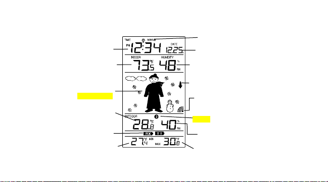
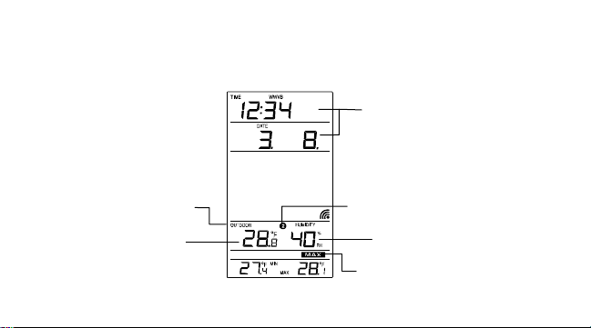
LCD SCREEN AND SETTINGS:
r
Weather Forecast icon
Daily outdoor min temp
Time
Indoor
Temperature
(Oscar Outlook)
Outdoo
Temperature
Low battery
indicator
Radio controlled time
reception On icon
Displays "date" or
"second"
Indoor Relative
Humidity %
Weather
Tendency icon
Outdoor
Reception
Signal*
Sensor identification
(channel No.)
21
Daily outdoormax temp
Outdoor Relative
Humidity %
Page 22

*When the outdoor signal is successfully received by the Weather Station, this icon will be
switched on. (If not successful, the icon will not be shown in LCD) So user can easily see whether
the last reception was successful (icon on) or not (icon off). On the other han d, the short blinking
of the icon shows that a reception is currently taking place.
For easy viewing the LCD screen is split into 5 sections displaying the information for time and
indoor data, weather forecast, and outdoor data.
Section 1 - TIME AND DATE
•
In normal mode, display the radio controlled time and date.
•
Display "second" of time when the "+" key is pressed
•
A time signal reception symbol will be shown indicating that receiver is receiving atomic
controlled time
22
Page 23

Section 2 - INDOOR TEMPERATURE AND INDOOR HUMIDITY
•
Display the current indoor temperature and humidity.
Section 3 - WEATHER ICON (FEATURING OSCAR OUTLOOK FORECASTER)
•
The weather is displayed in form of 15 weather icons (featuring Oscar Outlook For ecaster )
which change in appearance depending on the air pressure development (past air
pressure change) and the current outdoor temperature.
•
Display the weather tendency indicator
•
A signal reception symbol will be shown indicating that receiver is receiving outdoor data
•
Format of the Oscar Outlook icons refers to the "WEATHER FORECAST AND
TENDENCY"
Section 4 - OUTDOOR TEMPERATURE AND OUTDOOR HUMIDITY
•
Display the outdoor temperature and outdoor humidity of the currently selected channel.
23
Page 24

SECTION 5 – DAILY MIN AND MAX TEMPERATURE
•
Display the daily minimum and maximum temperature of the currently selected outdoor
channel.
ATOMIC TIME FUNCTION - WWVB RADIO CONTROLLED TIME
The NIST (National Institute of Standards and Technology—Time and Frequency Division)
WWVB radio station is located in Ft. Collins, Colorado, and transmits the exact time signal
continuously throughout the United States at 60 kHz. The signal can be received up to 2,000
miles away through the internal antenna in the Wireless Weather Station. However, due to the
nature of the Earth’s Ionosphere, reception is very limited during daylight hours. The Wireless
Weather Station will search for a signal every night when reception is best.
The WWVB radio station receives the time data from the NIST Atomic clock in Boulder, Colorado.
A team of atomic physicists is continually measuring every second, of every day, to an accuracy
of ten billionths of a second per day. These physicists have created an international standard,
24
Page 25

measuring a second as 9,192,631,770 vibrations of a Cesium-133 atom in a vacuum. For more
detail, visit http://www.boulder.nist.gov/timefreq.htm. To listen to the NIST time, call (303)499-
7111. This number will connect you to an automated time, announced at the top of the minute in
“Coordinated Universal Time”, which is also known as Greenwich Mean Time (GMT). This time
does not follow Daylight Saving Time changes. After the top of the minute, a tone will sound for
every second. It is possible that your Wireless Weather Station may not be exactly on the second
due to the variance in the quartz. However, the clock will adjust the quartz timing over the course
of several days to be very accurate; under 0.10 seconds per day
MANUAL SETTINGS:
The following manual settings can be done in the setting mode:
•
LCD contrast setting
•
Time zone setting
•
Daylight saving time setting
.
25
Page 26

•
Time reception ON/OFF setting
•
12/24-Hour setting
•
Manual time setting
•
Calendar setting
•
°F/ °C setting
•
Weather forecasting icon sensitivity setting
Press the SET key to advance to the setting mode:
LCD CONTRAST SETTING
flashing
26
Page 27

The LCD contrast can be set to 8 different levels to suit the users’ needs (default LCD contrast
setting is LCD 4). To set the desired contrast level:
1. The above display will be seen. Press the + key to select the level of contrast desired.
2. Press the SET key to confirm and enter the “Time Zone setting” or exit the setting mode
by pressing the CH key
TIME ZONE SETTING:
flashing
27
Page 28

The time zone default is "EST -5". To set a different time zone:
1. The current time zone value starts flashing.
2. Use the + key to set the time zone. The range runs from -5, -6, -7 …-12, 12, 11, 10… 0, -1,
-2, -3, -4 hr, in consecutive 1-hour intervals.
(The U.S. time zones are: -5hr(EST), -6hr(CST), -7hr(MST) and -8hr(PST), -9hr (ALA)
and -10hr (HAW).)
3. Confirm with the SET key and enter the Daylight Saving Time (DST) setting.
DAYLIGHT SAVING TIME SETTING ON/ OFF
flashing
28
Page 29

1. The digit “DST ON” will start flashing on the LCD.
2. Use the + key to turn On or OFF the daylight saving time function.
3. Confirm with the SET key and enter the “Time reception On/Off setting ” or exit the
setting mode by pressing the CH key.
TIME RECEPTION ON/OFF SETTING
(time reception icon)
Flashing
flashing
29
Page 30

In area where reception of the Atomic time (WWVB time) is not possible, the time reception
function can be turned OFF. The clock will then work as a normal Quartz clock. (Default setting is
ON).
1. The digit “ON” and the time reception icon will start flashing on the LCD.
2. Use the + key to turn OFF the time reception function.
3. Confirm with the SET key and enter the “12/24-Hour Display setting” or exit the setting
mode by pressing the CH key.
Note:
If the Time Reception function is turned OFF manually, the clock will not attempt any
reception of the Atomic time (WWVB time) as long as the Time Reception OFF function is
activated. The Time Reception icon will not be displayed on the LCD.
30
Page 31

12/24 HOUR TIME DISPLAY SETTING
1. After setting time reception ON/OFF, press the SET key, “12h” or “24h” flashes in the LCD.
(default 12 h)
2. Press the + key to select the “12h” or “24h” display mode.
3. Press the SET again to confirm and to enter the “Manual Time setting” or exit the setting
mode by pressing the CH key.
Note:
When 24h mode display is selected, the calendar format will be date and month display.
flashing
31
Page 32

When 12h mode display is selected, the calendar format will be month and date display.
MANUAL TIME SETTING
In case the Weather Station is not able to detect the Atomic time (WWVB) signal (disturbances,
transmitting distance, etc.), the time can be manually set. The clock will then work as a normal
Quartz clock.
Hours (flashing)
Minutes (flashing)
32
Page 33

To set the clock:
1. The hour digits start flashing in the time display section.
2. Use the + key to adjust the hours and then press SET key to go to the minute setting.
3. The minute will be flashing. Press the + key to just the minutes.
4. Confirm with the SET key and enter the “Calendar Setting” or exit the setting mode by
pressing the CH key
Note:
Daily WWVB reception (Atomic time) is attempted at full hour between 12:00 am to 6:00 am. If
the reception is successful, there will no reception attempt until the following day. When this is
successful, the received time will override the manually set time. The date is also updated with
the received time.
CALENDAR SETTING
33
Year
Page 34

The date default of the Weather Station is 1. 1. of the year 2006 after initial set-up. Once the
"Date. Month." (for 24h time display)
"Month. Date." (for 12h time display)
34
Page 35

radio-controlled time signals are received, the date is automatically updated. However, if the
signals are not received, the date can also be set manually. To do this:
1. Using the + key, set the year required. The range runs from 2003 to 20 29 (default is 2006).
2. Press the SET key to enter the month setting mode.
3. The month digit will be flashing. Press the + key to set the month and then press the SET
key to go to the date setting.
4. The date digit will be flashing. Press the + key to set the date.
5. Confirm with the SET key and enter the “°F/°C TEMPERATURE UNIT SETTING” or exit
the setting mode by pressing the CH key.
°F/°C TEMPERATURE UNIT SETTING
flashing
35
Page 36

The default temperature reading is set to °F (degrees Fahrenheit). To select °C (degrees
Celsius):
1. The “°F/ °C” will be flashing, use the + key to toggle between “°F” and “°C”.
2. Once the desired temperature unit has been chosen, confirm with the SET key and enter
the “Weather Forecast Icon Sensitivity setting” or exit the setting mode by pressing the
CH key.
WEATHER FORECASTING ICON SENSITIVITY SETTING
For locations with rapid changes of weather conditions, the threshold c an be set to a different
level for faster display of changing weather conditions.
36
Page 37

1. Using the + key to set the weather sensitivity level. There are 3 levels of setting: 2, 3 and 4.
The value corresponds to the change of air pressure in (hPa) before the weather icon will
switch to another state. Level 2 is the most sensitive setting, level 4 is the slowest
recording setting (default setting is "3").
Sensitivity level
(flashing)
37
Page 38

2. Confirm with the SET key and exit the Manual settings.
WEATHER FORECAST AND TENDENCY:
The weather forecast icons (Oscar Outlook):
One of the 15 different weather icons (featuring Oscar Outlook with different clothing) is displayed
in the centre of LCD, which indicates the different forecast weather condition due to air pressure
level (Sunny, Sunny + Cloudy or Cloudy + Rainy) and the current outdoor temperature
(Temperature value detected by Channel 1):
38
Page 39

Sunny
≥ 78.8°F
(26°C)
66.2 to 78.6°F
(19 to 25.9°C)
50 to 66°F
(10 to 18.9°C)
39
32 to 49.8°F
(0 to 9.9°C)
< 32°F (0°C)
Page 40

Sunny +
Cloudy
≥ 78.8°F
(26°C)
66.2 to
78.6°F
(19 to 25.9°C)
50 to 66°F
(10 to 18.9°C)
32 to 49.8°F
(0 to 9.9°C)
< 32°F (0°C)
40
Page 41

Note:
Cloudy +
Rainy
≥ 78.8°F
(26°C)
66.2 to
78.6°F
(19 to 25.9°C
50 to 66°F
(10 to 18.9°C)
)
32 to 49.8°F
(0 to 9.9°C)
< 32°F (0°C)
41
Page 42

After setting up, readings for weather forecasts should be disregarded for the next 48-60 hours.
This will allow sufficient time for the Weather Station to collect air pressure data at a constant
altitude and therefore result in a more accurate forecast.
Common to weather forecasting, absolute accuracy cannot be guaranteed. The weather
forecasting feature is estimated to have an accuracy level of about 75% due to the varying areas
the Weather Station has been designed for use in. In areas that e xperi ence sudden changes in
weather (for example from sunny to rain), the Weather Station will be more accurate compared to
use in areas where the weather is stagnant most of the time (for example mostly sunny).
If the Weather Station is moved to another location significantly higher or lower than its initial
standing point (for example from the ground floor to the upper floors of a house), remove the
batteries and re-insert them after about 30 seconds. By doing this, the Weather Station will not
mistake the new location as being a possible change in air-pressure when really it is due to the
42
Page 43

slight change of altitude. Again, disregard weather forecasts for the ne xt 48 to 60 hours as this
will allow time for operation at a constant altitude.
THE WEATHER TENDENCY INDICATOR
Working together with the weather icons are the weather tendency indicators (the upward and
downward arrow located near Oscar Outlook). When the indicator points upwards, it means that
the air-pressure is increasing and the weather is expected to improve, but when indicator points
downwards, the air-pressure is dropping and the weather is expected to become worse.
Therefore, user may see how the weather has changed and is expected to change. For example,
if the indicator is pointing downwards together with cloudy icons, it means that the last noticeable
change in the weather was when it was sunny (the sunny icon only). Therefore, the next change
in the weather will be the cloudy icons since the indicator is pointing downwards.
Note:
43
Page 44

Once the weather tendency indicator has registered a change in air pre ssure, it will remain
permanently visualized on the LCD.
DISPLAY OF INDOOR TEMPERATURE AND HUMIDITY READING:
The indoor temperature and humidity are measured and displayed on the second section of the
LCD.
Indoor icon
Indoor
Temperature
in °F
Indoor Relative
Humidity %
44
Page 45
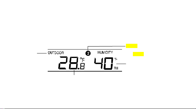
DISPLAY OF OUTDOOR TEMPERATURE AND HUMIDITY READING:
The outdoor temperature and humidity are measured and displayed on the fourth section of the
LCD.
Outdoor icon
Outdoor
Temperature in °F
45
Sensor identification No.
(shown when more than
one sensor is used)
Outdoor humidity %RH
Page 46

DISPLAY OF OUTDOOR MINIMUM AND MAXIMUM RECORDS:
1. In normal display mode, press the CH button to select the desired chan nel. The channel
ID will be displayed near the outdoor temperature reading.
2. Press the MIN/MAX button once, the max temperature and humidity of the selected
channel will be displayed. Also the time and date of recording this data will be displayed:
46
Page 47
Outdoor icon
Max temperature
Time and date of
recording the max
temperature
Channel No.
Max humidity
47
Max icon
Page 48

3. By pressing MIN/MAX button once more, the min temperature and humidity of the
selected channel will be shown. Also the time and date of recording this data will be
displayed.
4. Press one more time the MIN/ MAX button to advance to the indoor MIN/MAX
temperature and humidity display.
RESETTING THE OUTDOOR MINIMUM /MAXIMUM RECORDS
Note:
•
It is required to reset the outdoor MIN/MAX records of different channels separately.
•
The outdoor MIN and MAX records are to be reset separately.
1. In normal display mode, press the CH button to select a channel. The channel
Identification No. (channel No.) will be displayed above the outdoor temperature reading.
48
Page 49

Note: The sensor number will only be displayed if more than one sensor is applied.
2. Press the MIN/ MAX button once. The "max" icon will be displayed.
3. Press the SET button, this will reset the outdoor maximum temperature and humidity
record to the current value.
4. Press MIN/ MAX button once more to show the minimum data. The "min" icon will be
displayed.
5. Press the SET button, this will reset the outdoor minimum temperature and humidity
record to the current value.
6. Press three more times the MIN/MAX key to return to the normal display.
DISPLAY OF INDOOR MINIMUM AND MAXIMUM RECORDS:
49
Page 50

1. In normal display mode, press the MIN/ MAX button three times. The maximum indoor
f
temperature and humidity will be shown in the bottom section of LCD. Also the time and
date of recording the data will be displayed.
2. Then press the MIN/MAX button one more time, the minimum indoor temperature and
humidity will be shown at the bottom section of LCD. Also the time and date of recording
the data will be displayed:
recording the min
Time and date o
data
Indoor icon
Min temperature
50
Min humidity
Page 51

3. Press one more time the MIN/ MAX button to go back to the normal display.
RESETTING THE INDOOR MINIMUM /MAXIMUM RECORDS
1. In normal display mode, press the MIN/ MAX button three times to advance to the indoor
Max display.
2. Press the SET key once, this will reset the currently shown indoor maximum temperature
and humidity to the current time, date, temperature and humidity.
3. Press the MIN/ MAX button one more time to advance to the indoor Min display.
51
Page 52

4. Press the SET key once, this will reset the currently shown indoor minimum temperature
and humidity to the current time, date, temperature and humidity.
5. Press the MIN/MAX button once more to return to the normal display.
DAILY MINIMUM AND MAXIMUM OUTDOOR TEMPERATURE DISPLAY
This Weather Station will display the daily minimum and maximum outdoor temperature for each
outdoor channel, at the bottom of the LCD, in normal display.
Channel No.
Min daily temp
of the channel
Max daily temp of
52
the channel
Page 53

To view the daily minimum and maximum temperature of another channel, user shall press the
CH key in normal display.
Note:
The daily minimum temperature record is reset automatically at 8:00 pm and the daily maximum
temperature is reset automatically at 8:00 am every day.
915 MHz RECEPTION
The Weather Station should receive the temperature data within 15 minutes after set-up. If the
temperature data is not received 15 minutes after setting up (not successfully continuously, the
outdoor display shows “- - -” ), please check the following points:
53
Page 54

1. The distance of the Weather Station or sensor should be at least 5 to 6.5 feet (1.5 to 2
meters) away from any interfering sources such as computer monitors or TV sets.
2. Avoid positioning the Weather Station onto or in the immediate proximity of metal window
frames.
3. Using other electrical products such as headphones or speakers operating on the same
signal frequency (915MHz) may prevent correct signal transmission and reception.
4. Neighbors using electrical devices operating on the 915MHz signal frequency can also
cause interference.
Note:
When the 915MHz signal is received correctly, do not re-open the battery cover of either the
sensor or Weather Station, as the batteries may spring free from the contacts and force a false
reset. Should this happen accidentally then reset all units (see Setting up above) otherwise
transmission problems may occur.
54
Page 55

The transmission range is about 330 feet (100 m) from the sensor to the Weather Station (in
open space). However, this depends on the surrounding environment and interference levels. If
no reception is possible despite the observation of these factors , all system units have to be reset
(see Setting up).
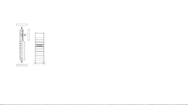
MOUNTING
POSITIONING THE WEATHER STATION:
The Weather Station may be hung onto wall easily or free standing.
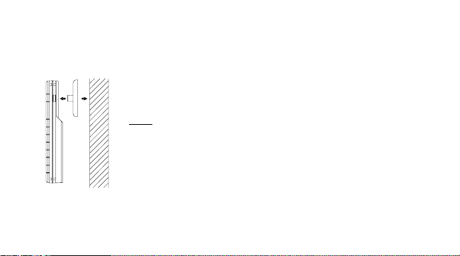
To wall mount
Choose a sheltered place. Avoid direct rain and sunshine.
Before wall mounting, please check that the outdoor temperature values can be
received from the desired locations.
1. Fix a screw (not supplied) into the desired wall, leaving the head
extended out the by about 5mm.
55
Page 56

2. Remove the stand from the Weather Station by pulling it away from the base and hang
the station onto the screw. Remember to ensure that it locks into place before releasing.
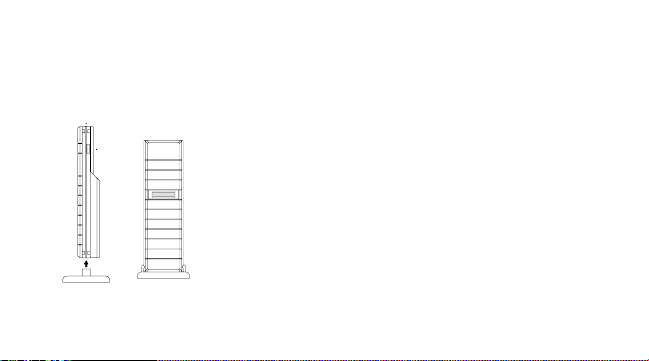
Free standing
With the foldout stand, the Weather Station can be placed onto any flat
surface.
56
Page 57
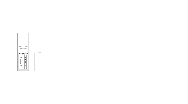
POSITIONING THE THERMO-HYGRO SENSOR:
The sensor is supplied with a holder that may be attached to a wall
with the two screws supplied. The sensor can also be position on a
flat surface by securing the stand to the bottom to the sensor.
57
Page 58
To wall mount:
1. Secure the bracket onto a desired wall using the screws and plastic
anchors.
2. Clip the remote thermo-hygro sensor onto the bracket.
Note:
Before permanently fixing the sensor wall base, place all units in the
desired locations to check that the outdoor temperature reading is
receivable. In event that the signal is not received, relocate the sensors
or move them slightly as this may help the signal reception.
58
Page 59

CARE AND MAINTENANCE:
•
Extreme temperatures, vibration and shock should be avoided as these may cause
damage to the unit and give inaccurate forecasts and readings.
•
When cleaning the display and casings, use a soft damp cloth only. Do not use solvents or
scouring agents as they may mark the LCD and casings.
•
Do not submerge the unit in water.
•
Immediately remove all low powered batteries to avoid leakage and damage. Replace only
with new batteries of the recommended type.
•
Do not make any repair attempts to the unit. Return them to their original point of purchase
for repair by a qualified engineer. Opening and tampering with the unit may invalidate its
guarantee.
59
Page 60

•
Do not expose the units to extreme and sudden temperature changes, this may lead to
rapid changes in forecasts and readings and thereby reduce their accuracy.
SPECIFICATIONS:
Temperature measuring range:
Indoor : 14.1°F to +139.8°F with 0.2°F resolution
(-9.9ºC to +59.9ºC with 0.1ºC resolution,
“OF.L” displayed if outside this range)
Outdoor : -39.8°F to +139.8°F with 0.2°F resolution
(-39.9ºC to +59.9ºC with 0.1ºC resolution,
“OF.L” displayed if outside this range)
Relative humidity measuring range:
Indoor : 1% to 99% with 1% resolution (displays “- -” when lower
60
Page 61

than 1 %; displays "99" % if higher than 99 %)
Outdoor : 1% to 99% with 1% resolution (displays “1” when lower
than 1 %; displays "99" % if higher than 99 %)
Indoor temperature checking interval : every 15 seconds
Indoor humidity checking interval : every 20 seconds
Outdoor data reception : every 4 seconds
Power supply:
Weather Station : 2 x AA, IEC, LR6, 1.5V
Thermo-hygro Sensor : 2 x AA, IEC, LR6, 1.5V
Battery life cycle (Alkaline batteries recommended)
Weather Station : Approximately 12 months
Thermo-hygro Sensor : Approximately 12 months
61
Page 62

Dimensions (L x W x H)
Weather Station : 3.18" x 1.22" x 5.64" (80.8 x 30.9 x 143.2 mm)
Thermo-hygro Sensor : 1.50" x 0.83" x 5.05" (38.2 x 21.2 x 128.3 mm)
WARRANTY
La Crosse Technology, Ltd provides a 1-year limited warranty on this product against
manufacturing defects in materials and workmanship.
This limited warranty begins on the original date of purchase, is valid only on products purchased
and used in North America and only to the original purchaser of this product. To receive warranty
service, the purchaser must contact La Crosse Technology, Ltd for problem determination and
service procedures. Warranty service can only be performed by a La Crosse Technology, Ltd
authorized service center. The original dated bill of sale must be presented upon request as
proof of purchase to La Crosse Technology, Ltd or La Crosse Technology, Ltd’s authorized
service center.
62
Page 63

La Crosse Technology, Ltd will repair or replace this product, at our option and at no charge as
stipulated herein, with new or reconditioned parts or products if found to be defective during the
limited warranty period specified above. All replaced parts and produc ts become the property of
La Crosse Technology, Ltd and must be returned to La Crosse Technology, Ltd. Replacement
parts and products assume the remaining original warranty, or ninety (90) days, whichever is
longer. La Crosse Technology, Ltd will pay all expenses for labor and materials for all repairs
covered by this warranty. If necessary repairs are not covered by this warrant y, or if a product is
examined which is not in need or repair, you will be charged for the repairs or examination. The
owner must pay any shipping charges incurred in getting your La Crosse Technology, Ltd product
to a La Crosse Technology, Ltd authorized service center. La Crosse Technology, Ltd will pay
ground return shipping charges to the owner of the product to a USA address only.
Your La Crosse Technology, Ltd warranty covers all defects in material and workmanship with
the following specified exceptions: (1) damage caused by accident, unreasonable use or neglect
63
Page 64

(including the lack of reasonable and necessary maintenance); (2) damage occurring during
shipment (claims must be presented to the carrier); (3) damage to, or deterioration of, any
accessory or decorative surface; (4) damage resulting from failure to follo w instructions contained
in your owner’s manual; (5) damage resulting from the performance of repairs or alterations by
someone other than an authorized La Crosse Technology, Ltd authorized service center; (6) units
used for other than home use (7) applications and uses that this product was not intended or (8)
the products inability to receive a signal due to any source of interference.. T his warranty covers
only actual defects within the product itself, and does not cover the cost of installation or removal
from a fixed installation, normal set-up or adjustments, claims based on misrepresentation by the
seller or performance variations resulting from installation-related circumstances.
LA CROSSE TECHNOLOGY, LTD WILL NOT ASSUME LIABILITY FOR INCIDENTAL,
CONSEQUENTIAL, PUNITIVE, OR OTHER SIMILAR DAMAGES ASSOCIATED WITH THE
OPERATION OR MALFUNCTION OF THIS PRODUCT. THIS PRODUCT IS NOT TO BE USED
FOR MEDICAL PURPOSES OR FOR PUBLIC INFORMATION. THIS PRODUCT IS NOT A
64
Page 65

TOY. KEEP OUT OF CHILDREN’S REACH.
This warranty gives you specific legal rights. You may also have other rights s pecific to your
State. Some States do no allow the exclusion of consequenti al or incidental damages therefore
the above exclusion of limitation may not apply to you.
For warranty work, technical support, or information contact:
La Crosse Technology, Ltd
2809 Losey Blvd. S.
La Crosse, WI 54601
Phone: 608.782.1610
Fax: 608.796.1020
e-mail:
65
Page 66

support@lacrossetechnology.com
(warranty work)
sales@lacrossetechnology.com
(information on other products)
www.lacrossetechnology.com
Question? Instructions? Please visit:
www.lacrossetechnology.com/9625
All rights reserved. This handbook must not be reproduced in any form, even in excerpts, or duplicated or
processed using electronic, mechanical or chemical procedures without written permission of the
publisher.
web:
66
Page 67

This handbook may contain mistakes and printing errors. The information in this handbook is regularly
checked and corrections made in the next issue. We accept no liability for technical mistakes or printing
errors, or their consequences.
All trademarks and patents are acknowledged.
67
 Loading...