

Page 1

WEATHER STATION
Contents
Language Page
____________________________________________________
English 1
French 35
Spanish 71
WS-9037U-IT
19
Page 2

TABLE OF CONTENTS
Topic Page
Inventory of Contents/ Additional Equipment 3
About WWVB 3
Quick Set Up Guide 4
Detailed Set Up Guide
Battery Installation 5
Start Up Sequence 6
Explanation of LCD Information 7
Function Key Layout 8
Program Mode
Overview of Programming Sequence 8
LCD Contrast Setting 8
Time Zone Setting 8-9
DST ON/OFF Setting 9
Radio-controlled Time ON/OFF Setting 9
12/24-hour Time Mode Setting 9-10
Setting the Time/Date Manually 10-11
Temperature Measuring Units (ºF/ºC) 11
Air Pressure Measuring Units (inHg/hPa) 11
Relative Pressure Setting 11-12
Forecast Sensitivity Setting 12
Features and Operation
Time Alarm Setting and Operation 13
Moon Phase 14
Minimum/Maximum Temperature/Humidity 14-15
Multiple Remote Temperature/Humidity Sensors 15-16
Comfort Icon 16
Weather Forecast and Pressure Trend Indicators 16
Weather Icons 17
Weather Tendency Arrows 17
Barometric Air Pressure Reading 18
Air Pressure History Bar Chart 18
Mounting 19-20
Maintenance and Care 21
Troubleshooting Guide 22
Specifications 23
Warranty Information 24-25
20
Page 3

WEATHER STATION
This product offers:
INVENTORY OF CONTENTS
1. Wireless Weather Station
2. Wireless Thermo-hygro Sensor (TX29UD-TH) and mounting bracket.
3. Instruction Manual
FEATURES:
The Weather Station
LCD display
Instruction Manual
INSTANT TRANSMISSION is the state-ofthe-art new wireless transmission
technology, exclusively designed and
developed by LA CROSSE
TECHNOLOGY. INSTANT
TRANSMISSION offers you an immediate
update (every 16 seconds!) of all your
outdoor data measured from the
transmitters: follow your climatic
variations in real-time!
Function keys
Hanging
hole
Battery
compartment
Stand
21
Page 4

• WWVB Radio controlled time with manual setting option
• Time reception ON/OFF (user selectable)
• 12/24 hour time display
• Daylight saving time (On/OFF)
• Time zone option ±12 hours
• Weekday and day calendar display (year and month only in setting
mode)
• Alarm setting with snooze function
• Display 12 Moon phases throughout the year
• Weather forecasting with weather tendency indicator
• Indoor comfort indicator
• Temperature display in ºC/ºF
• Indoor and outdoor temperature display with MIN/MAX records and
time of reception
• Humidity data display as RH%
• Indoor and outdoor humidity display with MIN/MAX records
• Relative air pressure hPa/ inHg with adjustable reference value
• Weather icon sensitivity setting
• Relative air pressure history for the past 24 hours (electronic
barometer with barometric pressure trend)
• LCD contrast selectable
• Wireless transmission at 915 MHz
• Signal reception intervals at 4 seconds
• Can receive up to 3 outdoor transmitters
• LED back light
• Low battery indicator
• Table standing or wall mounting
Thermo-Hygro Transmitter
• Remote transmission of outdoor temperature
and humidity to weather station by 915 MHz
signals
• Alternate display of temperature and humidity
display
• Water-resistant casing
• Wall mounting case. (Mount in a sheltered
place. Avoid direct rain and sunshine)
22
Page 5

SETTING UP
WHEN ONE TRANSMITTER IS USED
1. First, insert the batteries in the transmitter (see “How to install and
replace batteries in the Thermo-hygro outdoor transmitter”
above).
2. Within 2 minutes of powering up the transmitter, insert the batteries in
the Weather Station (see “How to install and replace batteries in
the Weather Station” above). Once the batteries are in place, all
segments of the LCD will light up briefly and a short signal tone will
sound. Following the indoor temperature/humidity and the time as
12:00 will be displayed. If these information are not displayed on the
LCD after 60 seconds, remove the batteries and wait for at least 60
seconds before reinserting them. Once the indoor data is displayed
user may proceed to the next step.
3. After the batteries are inserted, the Weather station will start receiving
data signal from the transmitter. The outdoor temperature and
humidity data should then be displayed on the Weather station. If this
does not happen after 2 minutes, the batteries will need to be
removed from both units and reset from step 1.
4. In order to ensure sufficient 915 MHz transmission however, the
distance between the Weather Station and the transmitter should not
be more than 330 feet (100 meters) (see notes on “Positioning” and
“915 MHz Reception”).
Note:
In the event of changing batteries of the units, ensure the batteries do not
spring free from the contacts. Always wait at least 1 minute after removing
the batteries before reinserting, otherwise start up and transmission
problems may occur.
WHEN MORE THAN ONE TRANSMITTER IS USED
1. User shall remove all the batteries from the Weather Station and
transmitters, and wait 60 seconds.
2. Insert the batteries in the first transmitter.
3. Within 2 minutes of powering up the first transmitter, insert the
batteries in the Weather Station. Once the batteries are in place, all
segments of the LCD will light up briefly and a short signal tine will
sound. Following the indoor temperature/humidity and the time as
12:00 will be displayed. If these information are not displayed on the
LCD after 60 seconds, remove the batteries from both units and wait
for at least 60 seconds before reinserting them.
4. The outdoor temperature and humidity data from the first transmitter
(channel 1) should then be displayed on the Weather Station. Also,
the signal reception icon will be displayed. If this does not happen
after 2 minutes, the batteries will need to be removed from both units
23
Page 6

and reset from step 1.
5. Insert the batteries in the second transmitter as soon as the outdoor
temperature and humidity readings from the first transmitter are
displayed on the Weather Station.
Note :
User shall insert the batteries into the second transmitter
within 45 seconds after the Weather Station displays the information
of the first transmitter.
6. The outdoor temperature and humidity from the second transmitter
and the "channel 2" icon should then be displayed on the Weather
Station. If this does not happen after 2 minutes, the batteries will
need to be removed from all the units and reset from step 1.
7. Insert the batteries in the third transmitter as soon as the "channel 2"
icon and outdoor data are displayed on the Weather Station. Then
within 2 minutes, the channel 3 outdoor data from the third transmitter
will be displayed and the channel icon will shift back to "1" once the
third transmitter is successfully received. If this is not happen, user
shall restart the setting up from step 1.
Note :
User shall insert the batteries into the third transmitter within
45 seconds after the Weather Station displays the information of the
first transmitter. Or immediately after reception of the second
transmitter is finished.
8. In order to ensure sufficient 915 MHz transmission however, the
distance between the Weather Station and the transmitter should not
be more than 330 feet (100 meters) (see notes on “Positioning” and
“915 MHz Reception”).
IMPORTANT:
Transmission problems will arise if the setting for additional sensors is not
followed as described above. Should transmission problems occur, it is
necessary to remove the batteries from all units and start again the set-up
from step 1.
Note:
• If the signal reception is not successful on the first frequency of
915MHz for 45 seconds, the frequency is changed to 920MHz and
the learning is tried for another 45 seconds. If it is still not successful
the reception is tried for 45 seconds on 910MHz. This will also be
done during re-synchronization.
• When the weather station is receiving the WWVB time signal, the
outdoor transmitter data signal will temporarily not be received by the
weather station. During this short period of time, the outdoor readings
shown on the weather station will not be renewed until the WWVB
time signal is successfully received.
24
Page 7

TO INSTALL AND REPLACE BATTERIES IN THE WEATHER
STATION
The Weather Station uses 3 x AA, IEC
LR6, 1.5V batteries. To install and replace
the batteries, please follow the steps
below:
1. Insert finger or other solid object in
the space at the bottom center of the
battery compartment and lift up to
remove the cover.
2. Insert batteries observing the correct
polarity (see marking).
3. Replace compartment cover.
TO INSTALL AND REPLACE BATTERIES IN THE THERMOHYGRO TRANSMITTER
The Thermo-hygro transmitter uses 2 x AA, IEC, LR6,
1.5V batteries. To install and replace the batteries,
please follow the steps below:
1. Remove the cover.
2. Insert the batteries, observing the correct polarity
(see marking).
3. Replace the battery cover.
Note:
In the event of changing batteries in any of the units, all units need to be
reset by following the setting up procedures. This is due to a random
security code assigned by the transmitter at start-up. This code must be
received and stored by the Weather Station in the first 3 minutes of power
being supplied to the transmitter.
BATTERY CHANGE:
It is recommended to replace the batteries in all units regularly to ensure
optimum accuracy of these units (Battery life see Specifications below).
Please participate in the preservation of the
environment. Return used batteries to an
authorized depot.
RESETTING
The Weather Station and the Thermo-hygro transmitter need to be reset
when one of the following conditions occur:
• Unsuccessful 915MHz signal reception.
25
Page 8

• Malfunction on the units.
• Batteries replacement.
For resetting, remove all batteries from the units. Wait at least for 1 minute
before powering up the Weather station again. Proceed from step 1 in
“Setting Up”.
ATOMIC TIME - WWVB RADIO CONTROLLED TIME
The NIST (National Institute of Standards and Technology—Time and
Frequency Division) WWVB radio station is located in Ft. Collins, Colorado,
and transmits the exact time signal continuously throughout the United
States at 60 kHz. The signal can be received up to 2,000 miles away
through the internal antenna in the Weather Station. However, due to the
nature of the Earth’s Ionosphere, reception is very limited during daylight
hours. The wireless weather station will search for a signal every night
when reception is best.
The WWVB radio station receives the time data from the NIST Atomic clock
in Boulder, Colorado. A team of atomic physicists is continually measuring
every second, of every day, to an accuracy of ten billionths of a second per
day. These physicists have created an international standard, measuring a
second as 9,192,631,770 vibrations of a Cesium-133 atom in a vacuum.
For more detail, visit http://www.boulder.nist.gov/timefreq.htm. To listen to
the NIST time, call (303)499-7111. This number will connect you to an
automated time, announced at the top of the minute in “Coordinated
Universal Time”, which is also known as Greenwich Mean Time (GMT).
This time does not follow Daylight Saving Time changes. After the top of
the minute, a tone will sound for every second. It is possible that your
wireless weather station will not be exactly on the second due to the
variance in the quartz. However, the clock will adjust the quartz timing over
the course of several days to be very accurate; under 0.10 seconds per
day.
FUNCTION KEYS:
Weather Station:
The Weather Station has 5 easy to use function keys, located on the right
side of the weather station:
26
Page 9

SET key
IN key
OUT/+ key
ALM/DATE key
SNOOZE/CH key
SET key
• Press and hold the key to enter manual setting modes: LCD contrast,
time zone, DST ON/OFF, time reception ON/OFF, 12/24 hour display,
manual time setting, calendar, temperature °C/°F, pressure hPa/inHg,
relative pressure value, and weather icon sensitivity setting
• Reset all MIN/MAX records
• Stop the alarm during alarm ringing
• Stop snooze mode
• Back-light on
ALM/DATE key
• Press and hold key for 3 seconds to enter the alarm setting mode
• Active/de-active the alarm time
• Stop the alarm during alarm ringing
• Stop snooze mode
• Display date
• Back-light on
IN key
• Press to toggle between MAX/MIN and current indoor
temperature/humidity data
• Press to set the alarm hour (inside alarm setting mode)
• Decrease relative pressure value (within manual set mode)
• Stop the alarm during alarm ringing
• Stop snooze mode
• Back-light on
27
Page 10

OUT/+ key
• Press shortly to toggle between MAX/MIN and current outdoor
temperature/humidity data
• Increase, change, toggle all values in manual set mode
• Press to set the alarm minute (inside alarm setting mode)
• Stop the alarm during alarm ringing
• Stop snooze mode
• Back-light on
SNOOZE/CH key
• Active snooze function during alarm ringing
• Exit the manual set mode and alarm setting mode
• Switch among display of channels (if more than 1 transmitter is used)
• Back-light on
28
Page 11

LCD SCREEN
The LCD screen is split into 4 sections displaying the information for
time/calendar/alarm/moon phase, indoor data, weather forecast and
outdoor data.
Time reception icon
(for WWVB tim e)
Moon phase icon
Low battery
indicator
Indoor temperature
in ºC/ ºF
Weather tendency
indicator
Relative air pressure
history bar graph
Time
Calendar or alarm time
Comfort indicator icon
Indoor relative
humidity in RH%
Weather forecast icon
Relative air pressure
in hPa / inHg
Outdoor data signal
reception indicator*
Outdoor temperature in ºC/ ºF
Outdoor relative humidity in RH%
* When the signal is successfully received by the Weather Station, the
outdoor transmission icon will be switched on. (If not successful, the icon
will not be shown on LCD). The user can then easily see whether the last
reception was successful (icon on) or not (icon off). On the other hand, the
short blinking of the icon shows that a reception is currently taking place.
MANUAL SETTINGS:
The following manual settings can be changed when pressing the SET key
for:
• LCD contrast setting
• Time zone setting
• DST ON/ OFF setting (daylight saving time)
• Time reception ON/OFF setting
• 12/24-hour format setting
• Manual time setting
• Calendar setting
29
Page 12

• °C/°F temperature setting
• hPa / inHg pressure setting
• Relative air pressure setting
• Weather forecasting icon sensitivity setting
LCD CONTRAST SETTING:
The LCD contrast can be set within 8 levels, from LCD 0 to LCD7 (Default
setting is LCD 4):
1. Press and hold the SET key until the digit starts flashing.
2. Use the OUT/+ key to view all levels of contrast.
3. Select the desired LCD contrast. Confirm with the SET key and enter
in the Time Zone setting.
Last digit flashing
TIME ZONE SETTING:
Flashing
The time zone default of the Weather Station is “-5h”. To set a different
time zone:
1. The current time zone value starts flashing.
2. Use the OUT/+ key to set the time zone. The range runs from 0 to -12
and then runs from +12 back to 0 in consecutive 1-hour intervals.
3. Confirm with the SET key and enter the Daylight saving time
ON/OFF setting.
DAYLIGHT SAVING TIME ON/ OFF SETTING
Daylight time saving (DST) function can be set ON/OFF. Default setting
“ON”
1. The digit “ON” will start flashing on the LCD.
2. Use the OUT/+ key to turn OFF the daylight time saving function.
3. Confirm with the SET key and enter the Time reception ON/OFF
setting.
Digit flashing
30
Page 13

TIME RECEPTION ON/OFF SETTING:
In area where reception of the WWVB time is not possible, the WWVB time
reception function can be turn OFF. The clock will then work as a normal
Quartz clock. (Default setting is ON).
4. The digit “ON” will start flashing on the LCD.
5. Use the OUT/+ key to turn OFF the time reception function.
6. Confirm with the SET key and enter the 12/24-hour format setting.
Note:
If the Time Reception function is turn OFF manually, the clock will not
attempt any reception of the WWVB time as long as the Time
Reception OFF function is activated.
The time reception icon and the “WWVB” icon will not be displayed
on the LCD.
Flashing
12/24-HOUR FORMAT SETTING:
The hour display can be selected to show hours in 12-hour or 24-hour
settings. (Default 12-Hour)
1. Use the OUT/+ key to toggle between “12H” or “24H”.
2. Confirm with the SET key and enter the Manual time setting.
MANUAL TIME SETTING:
In case the Weather Station cannot detect the WWVB-signal (for example
due to disturbances, transmitting distance, etc.), the time can be manually
set. The clock will then work as a normal Quartz clock.
Hour flashing
1. The hour digit will start flashing.
2. Use the OUT/+ key to set the hour.
Minutes flashing
Flashing
31
Page 14

3. Press again the SET key to set the minutes. The minute digits start
flashing.
4. Use the OUT/+ key to set the minutes.
5. Confirm with the SET key and enter the Calendar setting.
Note:
The unit will still try to receive the signal between 0:00 and 6:00 am every
day despite it being manually set, if the WWVB reception function has been
set ON. When it does receive the signal, it will change the manually set
time into the received time. During reception attempts the WWVB tower
icon will flash. If reception has been unsuccessful, then the WWVB tower
icon will not appear but reception will still be attempted the following hour.
CALENDAR SETTING:
Year
Date and month (24hr time format)
Month and date (12hr time format)
The date default of the Weather station is 1. 1. 2006. Once the radiocontrolled time signals are received, the date is automatically updated.
However, if the signals are not received, the date can also be set manually.
1. The year starts flashing.
2. Use the OUT/+ key to set the year (between year 2003-2029).
3. Press the SET key again to confirm and to enter the month setting.
The month starts flashing.
4. Use the OUT/+ key to set the month.
5. Press the SET key again to confirm and to enter the date setting
mode. The date starts flashing.
6. Use the OUT/+ key to set the date.
7. Confirm all calendar settings with the SET key and enter the
Temperature unit setting.
°C/°F TEMPERATURE SETTING:
The temperature display can be selected to show temperature data in °C or
°F (Default °F).
1. Use the OUT/+ key to toggle between “°C” or “°F”.
Flashing
32
Page 15

2. Confirm with the SET key and enter the Air pressure unit setting.
hPa / inHg PRESSURE UNIT SETTING:
The pressure display can be selected to show relative air pressure in hPa
or inHg (default is “inHg”).
Flashing
1. Use the OUT/+ key to toggle between “hPa” or “inHg” unit.
2. Confirm with the SET key and enter the Relative air pressure value
setting.
Note: Units of weather icon sensitivity and air pressure history are not
affected. They are always expressed in hPa.
RELATIVE AIR PRESSURE VALUE SETTING
The default relative pressure value is 29.92 inHg (1013 hPa). This can be
manually set to another value within the range of 28.35 – 30.72 inHg (960 –
1040 hPa) for a better reference.
1. The current relative pressure value will start flashing
Flashing
2. Use the OUT/+ key to increment and IN key to decrement the value.
3. Keep holding the key allows the value to advance faster.
4. Confirm with the SET key and enter the Weather forecast icon
sensitivity setting.
WEATHER FORECASTING ICON SENSITIVITY SETTING:
For locations with rapid changes of weather conditions, the weather icons
sensitivity can be set to a different level for faster display of weather
conditions.
Flashing
33
Page 16

1. The current sensitivity value will start flashing.
2. Use the OUT/+ key to set the weather sensitivity level. There are 3
levels of setting: 2, 3 and 4. The value corresponds to the change of
air pressure in hPa before the weather icon will switch to another
state. Level 2 is the most sensitive setting, level 4 is the slowest
recording setting (default setting is "3").
3. Confirm with the SET key and exit the Manual settings.
TO EXIT THE MANUAL SETTING MODE
To exit the manual setting mode anytime during the manual setting, press
the SNOOZE/CH key or wait for automatic timeout. The mode will return to
normal time display.
ALARM SETTING:
The alarm time can be set when pressing the ALM/DATE key.
Alarm icons
Alarm time
1. Press and hold the ALM/DATE key to enter the alarm set mode. The
alarm digits flash.
2. Use the IN key to set the alarm hour.
3. Use the OUT/+ key to set the alarm minute.
4. Confirm with SNOOZE/CH key and exit the Alarm setting. The icon
((●)) will be displayed along with the set alarm time.
Note:
If the calendar is displayed in the Weather station, the alarm is NOT active.
To view and active the alarm, press the ALM/DATE key. The alarm icon
and the alarm time will be displayed, indicating that the alarm setting is
activated.
The maximum alarm ring duration is 2 minutes.
SNOOZE SETTING AND STOPPING THE ALARM:
10 minutes snooze function can be set when the alarm is ringing by
pressing the SNOOZE/CH key.
When the alarm is snoozing, the alarm icon ((•)) will remain flashing
indicating that the alarm is active but is in Snooze mode. To stop the
snooze function when it is in snooze period, press any key except the
SNOOZE/CH key.
To stop the alarm, press any key during alarm ringing, except the
SNOOZE/CH key.
34
Page 17

MOON PHASES SYMBOL
The Moon icon of the Weather station will also display all 12 Moon phases
throughout the year according to the set calendar.
New
Moon
Small
Waning
Crescent
Small
Waxing
Crescent
Large
Waning
Crescent
Large
Waxing
Crescent
Last
Quarter
First
Quarter
Small
Waning
Gibbous
Small
Waxing
Gibbous
Large
Waning
Gibbous
Large
Waxing
Gibbous
Full Moon
INDOOR RELATIVE HUMIDITY AND INDOOR
TEMPERATURE:
The indoor temperature and humidity data, the indoor comfort indicator are
automatically updated and displayed on the second section of the LCD.
Indoor temperature
in °C or ºF
MAX icon
Indoor relative
humidity in RH%
THE COMFORT LEVEL INDICATOR:
Comfortable : A happy face icon “☺” indicating a temperature level
Uncomfortable : A sad face icon “” indicating any value outside the
between 20°C and 25.9°C and relative humidity
reading between 45% and 65%.
comfortable range.
TOGGLING AND RESETTING THE INDOOR READINGS:
1. Press the IN key to toggle between the indoor current, MAX/MIN
temperature and humidity data. The time and dates of the recorded
data will also be displayed in the time and calendar sections (for
temperature data only).
Once to show the MAX indoor temperature and humidity data with
the recorded time and date.
Twice to show the MIN indoor temperature and humidity data with
the recorded time and date.
Three times to return to the current displayed values
35
Page 18

2. Once the MIN or MAX data is displayed, press and hold the SET key
for 3 seconds to reset the respective MIN or MAX record to current
temperature and humidity data, and current time, date display.
Note: The MIN or MAX data needs to be reset individually.
WEATHER FORECAST AND WEATHER TENDENCY:
WEATHER FORECASTING ICONS:
Weather icons in the third section of LCD can be displayed in any of the
following combinations:
FORECAST
Sunny Cloudy with sunny intervals Rainy
For every sudden or significant change in the air pressure, the weather
icons will update accordingly to represent the change in weather. If the
icons do not change, then it means either the air pressure has not changed
or the change has been too slow for the Weather station to register.
However, if the icon displayed is a sun or raining cloud, there will be no
change of icon if the weather gets any better (with sunny icon) or worse
(with rainy icon) since the icons are already at their extremes.
The icons displayed forecasts the weather in terms of getting better or
worse and not necessarily sunny or rainy as each icon indicates. For
example, if the current weather is cloudy and the rainy icon is displayed, it
does not mean that the product is faulty because it is not raining. It simply
means that the air pressure has dropped and the weather is expected to
get worse but not necessarily rainy.
Note:
After setting up, readings for weather forecasts should be disregarded for
the next 12-24 hours. This will allow sufficient time for the Weather station
to collect air pressure data at a constant altitude and therefore result in a
more accurate forecast.
Common to weather forecasting, absolute accuracy cannot be guaranteed.
The weather forecasting feature is estimated to have an accuracy level of
about 75% due to the varying areas the Weather station has been
designed for use. In areas that experience sudden changes in weather (for
example from sunny to rain), the Weather station will be more accurate
compared to use in areas where the weather is stagnant most of the time
(for example mostly sunny).
If the Weather station is moved to another location significantly higher or
lower than its initial standing point (for example from the ground floor to the
upper floors of a house), discard the weather forecast for the next 12-24
FORECAST
FORECAST
36
Page 19

hours. By doing this, the Weather Station will not mistake the new location
as being a possible change in air-pressure when really it is due to the slight
change of altitude.
WEATHER TENDENCY INDICATOR
Working together with the weather icons is the weather tendency indicators
(located on the left and right sides of the weather icons). When the
indicator points upwards, it means that the air-pressure is increasing and
the weather is expected to improve, but when indicator points downwards,
the air-pressure is dropping and the weather is expected to become worse.
Taking this into account, one can see how the weather has changed and is
expected to change. For example, if the indicator is pointing downwards
together with cloud and sun icons, then the last noticeable change in the
weather was when it was sunny (the sun icon only). Therefore, the next
change in the weather will be cloud with rain icons since the indicator is
pointing downwards.
Note:
Once the weather tendency indicator has registered a change in air
pressure, it will remain permanently visualized on the LCD.
AIR PRESSURE HISTORY (ELECTRONIC BAROMETER WITH
BAROMETRIC PRESSURE TREND)
The third section of the LCD also shows the relative air pressure value and
the air pressure history.
The bar chart indicates the air pressure history trend over the last 24 hours
in 7 steps, 0h, -3h, -6h, -9h, -12h, -18h, and -24h. The “0h” represents the
current full hour air pressure recording. The columns represent the “hPa”
(0, ±2, ±4, ±6) at specific time. The “0” in the middle of this scale is equal to
the current pressure and each change (±2, ±4, ±6) represents how high or
low in “hPa“ the past pressure was compared to the current pressure.
If the bars are rising it means that the weather is getting better due to the
increase of air pressure. If the bars go down, it means the air pressure has
dropped and the weather is expected to get worse from the present time
“0h“.
Note:
For accurate barometric pressure trends, the Weather Station should
operate at the same altitude for example, it should not be moved from the
Air pressure over the last 24 hours
37
Page 20

ground to the second floor of the house. Should the unit be moved to a new
location, discard readings for the next 12-24 hours.
OUTDOOR TEMPERATURE/HUMIDITY DATA
The fourth LCD section shows the outdoor temperature and humidity, the
reception indicator, the transmitter identification number and the MIN/MAX
outdoor data.
Outdoor
temperature
in °C/ °F
MIN icon
Outdoor transmitter identification number
Outdoor relative
humidity in RH%
TOGGLING AND RESETTING THE OUTDOOR DATA
1. To toggle between the outdoor current, MAX/MIN temperature and
humidity data and the times (for temperature data only) they were
recorded press the OUT/+ key:
Once to show the MAX outdoor temperature and humidity data with
the recorded time and date.
Twice to show the MIN outdoor temperature and humidity data with
the recorded time and date.
Three times to return to the current displayed values.
2. Once the MIN or MAX data is displayed, press and hold the SET key
for 3 seconds to reset the respective MIN or MAX record to current
temperature and humidity data, and current time, date display.
Note: The MIN or MAX data needs to be reset individually.
TO VIEW THE MIN/MAX DATA FROM DIFFERENT
TRANSMITTERS
When more than 1 transmitter used:
1. To toggle between transmitters, press the SNOOZE/CH key:
Once to show transmitter 2
Twice to show transmitter 3
Three times to return to transmitter 1
2. Use OUT/+ key to view the MIN/MAX temperature and humidity data
for the selected transmitter.
3. To reset the minimum and maximum temperature and humidity data,
and the times at which they were recorded, press the SET key
continuously for about 3 seconds. This will reset the MIN/MAX data
recorded to the current time, date, temperature and humidity. The
current time taken is the normal displayed time and does not regard
the time zone set for the unit.
Note: the MIN/MAX data for each transmitter needs to be reset separately.
38
Page 21

BACK-LIGHT
The back-light is automatically switched ON when any keys are pressed.
The back-light will be switched on for approximately 8 seconds before
automatically switching OFF.
LOW BATTERY INDICATOR
Low battery indicator is displayed on the LCD when the batteries require
changing.
ABOUT THE OUTDOOR TRANSMITTER
The range of the Thermo-hygro transmitter may be affected by the
temperature. At cold temperatures the transmitting distance may be
decreased. Please bear this in mind when positioning the transmitters. Also
the batteries may be reduced in power for the Thermo-hygro transmitter.
CHECKING FOR 915MHz RECEPTION
If the outdoor temperature and humidity data are not being received within
three minutes after setting up (or outdoor display always show “- -. -” in the
outdoor section of the Weather station during normal operation), please
check the following points:
1. The distance of the Weather station or transmitters should be at least
6 feet (2 meters) away from any interfering sources such as computer
monitors or TV sets.
2. Avoid placing the transmitters onto or in the immediate proximity of
metal window frames.
3. Using other electrical products such as headphones or speakers
operating on the 915MHz-signal frequency may prevent correct signal
transmission or reception. Neighbors using electrical devices
operating on the 915MHz-signal frequency can also cause
interference.
Note:
When the 915MHz signal is received correctly, do not re-open the battery
cover of either the transmitter or Weather station, as the batteries may
spring free from the contacts and force a false reset. Should this happen
accidentally then reset all units (see “Setting up” above) otherwise
transmission problems may occur.
The transmission range is around 330 feet (100 meters) from the Thermohygro transmitter to the Weather station (in open space). However, this
depends on the surrounding environment and interference levels. If no
reception is possible despite the observation of these factors, all system
units have to be reset (see “Setting up” above).
39
Page 22
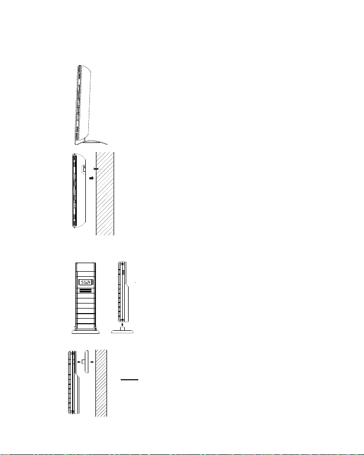
POSITIONING THE WEATHER STATION:
The weather station has been designed to be hang on a wall or free
standing.
For free standing:
Simply attached the stand to the bottom of the unit and
place onto a flat surface.
To wall mount
Choose a sheltered place. Avoid direct rain and
sunshine.
Before wall mounting, please check that the outdoor
temperature and humidity values can be received from
the desired locations. To wall mount:
1. Fix a screw (not supplied) into the desired wall,
leaving the head extended out the by about 0.2”
(5mm).
2. Hang it onto the screw. Remember to ensure that
it locks into place before releasing.
POSITIONING THE THERMO-HYGRO TRANSMITTER
The thermo-hygro transmitter is supplied with a
holder that may be attached to a wall with the
two screws supplied. The sensor can also be
position on a flat surface by securing the stand
to the bottom to the sensor.
To wall mount:
1. Secure the bracket onto a desired wall using the
screws and plastic anchors.
2. Clip the sensor onto the bracket.
Note:
Before permanently fixing the sensor wall base, place all
units in the desired locations to check that the outdoor
40
Page 23

temperature and humidity readings are receivable. In event that the signal
is not received, relocate the sensor(s) or move them slightly as this may
help the signal reception.
CARE AND MAINTENANCE:
• Extreme temperatures, vibration and shock should be avoided as
these may cause damage to the unit and give inaccurate forecasts
and readings.
• Precautions shall be taken when handling the batteries. Injuries,
burns, or property damage may be resulted if the batteries are in
contact with conducting materials, heat, corrosive materials or
explosives. The batteries shall be taken out from the unit before the
product is to be stored for a long period of time.
• Immediately remove all low powered batteries to avoid leakage and
damage. Replace only with new batteries of the recommended type.
• When cleaning the display and casings, use a soft damp cloth only.
Do not use solvents or scouring agents as they may mark the LCD
and casings.
• Do not submerge the unit in water.
• Special care shall be taken when handling a damaged LCD display.
The liquid crystals can be harmful to user's health.
• Do not make any repair attempts to the unit. Return them to their
original point of purchase for repair by a qualified engineer. Opening
and tampering with the unit may invalidate their guarantee.
• Never touch the exposed electronic circuit of the device as there is a
danger of electric shock should it become exposed.
• Do not expose the units to extreme and sudden temperature
changes, this may lead to rapid changes in forecasts and readings
and thereby reduce their accuracy.
SPECIFICATIONS:
Temperature measuring range:
Indoor : 14.2ºF to 139.8ºF with 0.2ºF resolution
-9.9ºC to +59.9ºC with 0.1°C resolution
(“OF.L” displayed if outside this range)
Outdoor : -39.8ºF to +139.8ºF with 0.2ºF resolution
-39.9ºC to +59.9ºC with 0.1°C resolution
(“OF.L” displayed if outside this range)
Indoor humidity range : 1% to 99% with 1% resolution
(Display “- -“ if temperature is OL.F; display “- -“ if < 1% and “99%” if >
99%)
Outdoor humidity range : 1% to 99% with 1% resolution
(Display “- -“ if outside temperature is OF.L; display 1% if < 1% and 99% if
> 99%)
41
Page 24

Interior data checking intervals
Indoor Temperature : Every 15 seconds
Humidity : Every 20 seconds
Air pressure checking interval : Every 15 seconds
Outdoor temperature and humidity data checking interval:
Every 4 seconds (or every 15 minutes if data are lost and display “--.-“)
Transmission range : up to 330 feet /100 meters (open space)
Power consumption: (alkaline batteries recommended)
Weather station : 3 x AA, IEC LR6, 1.5V
Thermo-hygro transmitter : 2 x AA, IEC LR6, 1.5V
Battery life : up to 24 months
Dimensions (L x W x H):
Weather station : 6.88” x 4.72” x 1.22” / 175 x 120 x 31 mm
Thermo-hygro transmitter : 1.50" x 0.83" x 5.05"/ 38.2 x 21.2 x 128.3mm
LIABILITY DISCLAIMER
• The electrical and electronic wastes contain hazardous substances.
Disposal of electronic waste in wild country and/or in unauthorized
grounds strongly damages the environment
• Please contact your local or/and regional authorities to retrieve the
addresses of legal dumping grounds with selective collection
• All electronic instruments must from now on be recycled. User shall
take an active part in the reuse, recycling and recovery of the
electrical and electronic waste.
• The unrestricted disposal of electronic waste may do harm on public
health and the quality of environment.
• This product must however not be thrown in general rubbish
collection points.
• As stated on the gift box and labeled on the product, reading the
“User manual” is highly recommended for the benefit of the user.
• The manufacturer and supplier cannot accept any responsibility for
any incorrect readings and any consequences that occur should an
inaccurate reading take place.
• This product is not to be used for medical purposes or for public
information.
• This product is only designed to be used in the home as indication of
the future weather and is not 100% accurate. Weather forecasts
given by this product should be taken only as an indication and not as
being totally accurate.
• The specifications of this product may change without prior notice.
• This product is not a toy. Keep out of the reach of children.
• No part of this manual may be reproduced without written consent of
the manufacturer.
42
Page 25

WARRANTY
La Crosse Technology, Ltd provides a 1-year limited warranty on this
product against manufacturing defects in materials and workmanship.
This limited warranty begins on the original date of purchase, is valid only
on products purchased and used in North America and only to the original
purchaser of this product. To receive warranty service, the purchaser must
contact La Crosse Technology, Ltd for problem determination and service
procedures. Warranty service can only be performed by a La Crosse
Technology, Ltd authorized service center. The original dated bill of sale
must be presented upon request as proof of purchase to La Crosse
Technology, Ltd or La Crosse Technology, Ltd’s authorized service center.
La Crosse Technology, Ltd will repair or replace this product, at our option
and at no charge as stipulated herein, with new or reconditioned parts or
products if found to be defective during the limited warranty period
specified above. All replaced parts and products become the property of
La Crosse Technology, Ltd and must be returned to La Crosse Technology,
Ltd.
Replacement parts and products assume the remaining original warranty,
or ninety (90) days, whichever is longer. La Crosse Technology, Ltd will
pay all expenses for labor and materials for all repairs covered by this
warranty. If necessary repairs are not covered by this warranty, or if a
product is examined which is not in need or repair, you will be charged for
the repairs or examination.
The owner must pay any shipping charges incurred in getting your La
Crosse Technology, Ltd product to a La Crosse Technology, Ltd authorized
service center.
Your La Crosse Technology, Ltd warranty covers all defects in material and
workmanship with the following specified exceptions: (1) damage caused
by accident, unreasonable use or neglect (including the lack of reasonable
and necessary maintenance); (2) damage occurring during shipment
(claims must be presented to the carrier); (3) damage to, or deterioration of,
any accessory or decorative surface; (4) damage resulting from failure to
follow instructions contained in your owner’s manual; (5) damage resulting
from the performance of repairs or alterations by someone other than an
authorized La Crosse Technology, Ltd authorized service center; (6) units
used for other than home use (7) applications and uses that this product
was not intended or (8) the products inability to receive a signal due to any
source of interference.
This warranty covers only actual defects within the product itself, and does
not cover the cost of installation or removal from a fixed installation, normal
43
Page 26

set-up or adjustments, claims based on misrepresentation by the seller or
performance variations resulting from installation-related circumstances.
LA CROSSE TECHNOLOGY, LTD WILL NOT ASSUME LIABILITY FOR
INCIDENTAL, CONSEQUENTIAL, PUNITIVE, OR OTHER SIMILAR
DAMAGES ASSOCIATED WITH THE OPERATION OR MALFUNCTION
OF THIS PRODUCT. THIS PRODUCT IS NOT TO BE USED FOR
MEDICAL PURPOSES OR FOR PUBLIC INFORMATION. THIS
PRODUCT IS NOT A TOY. KEEP OUT OF CHILDREN’S REACH.
This warranty gives you specific legal rights. You may also have other
rights specific to your State. Some States do no allow the exclusion of
consequential or incidental damages therefore the above exclusion of
limitation may not apply to you.
For warranty work, technical support, or information contact:
Please visit: www.lacrossetechnology.com/9037
All rights reserved. This handbook must not be reproduced in any form, even in
excerpts, or duplicated or processed using electronic, mechanical or chemical
procedures without written permission of the publisher.
This handbook may contain mistakes and printing errors. The information in this
handbook is regularly checked and corrections made in the next issue. We accept no
liability for technical mistakes or printing errors, or their consequences. All trademarks
and patents are acknowledged.
La Crosse Technology, Ltd
2809 Losey Blvd. S.
La Crosse, WI 54601
Phone: 608.782.1610
Fax: 608.796.1020
support@lacrossetechnology.com
sales@lacrossetechnology.com
(information on other products)
www.lacrossetechnology.com
e-mail:
(warranty work)
web:
Question? Instructions?
44
Page 27

915 MHz WIRELESS TEMPERATURE STATION
WS-9080U-IT
Instruction manual
Page 28

Contents
Language Page
___________________________________________________________________
English 1
French 41
Spanish 79
1
Page 29

TABLE OF CONTENTS
Topic Page
Inventory of Contents 3
Features 4
Setting Up 6
Battery Installation 10
Function Keys 12
LCD Screen and Settings 14
Atomic Time -WWVB Radio Controlled Time 16
Manual Settings 17
Display of Indoor Temperature Reading 25
Display of Outdoor Temperature Reading 26
Display of Indoor Minimum and Maximum records 26
Display of Outdoor Minimum and Maximum records 28
Daily Indoor Minimum and Maximum Temperature display 29
Daily Outdoor Minimum and Maximum Temperature display 30
915 MHz Reception 31
Mounting 32
Care and Maintenance 34
Specifications 35
Warranty 36
2
Page 30

This product offers:
INSTANT TRANSMISSION is the state-of-the-art new
wireless transmission technology, exclusively
designed and developed by LA CROSSE
TECHNOLOGY. INSTANT TRANSMISSION offers you
an immediate update (every 4 seconds!) of all your
outdoor data measured from the sensors: follow your
climatic variations in real-time!
INVENTORY OF CONTENTS
1. Wireless Temperature Station
2. Wireless Temperature Sensor (TX29U) and mounting bracket.
3. Instruction Manual and Warranty Card.
3
Page 31

FEATURES:
The Temperature Station
LCD
Display
Hanging hole
Battery
compartment
cover
Function
Keys
Foldout
Stand
4
Page 32

• Atomic Time function (WWVB Radio controlled time) or manual time setting options
• Atomic Time reception On/Off
• Daylight Saving Time ON/OFF
• 12/24 hour display
• Hour and minute display
• Calendar display
• Time zone option ±12 hours
• Wireless transmission at 915 MHz
• Outdoor signal reception intervals at 4-second
• Temperature display in degrees Fahrenheit (°F) or Celsius (°C) selectable
• Indoor and Outdoor temperature display with MIN/MAX recording (records can be
reset)
• Can receive up to 3 outdoor sensors
• Daily minimum and maximum indoor temperature display
• Daily minimum and maximum outdoor temperature display
• Low battery indicator
• LCD contrast adjustable
• Table standing/ Wall mounting
5
Page 33

The Outdoor Temperature Sensor
• Remote transmission of outdoor temperature to
Temperature Station by 915 MHz
• Water-resistant casing
• Wall mounting case (Mount in a sheltered place. Avoid
direct rain and sunshine)
SETTING UP:
When one Sensor is used
1. First, insert the batteries into the temperature sensor. (see “Install and replace
batteries in the temperature sensor“).
2. Immediately after and within 30 seconds, insert the batteries into Temperature
Station (see “Install and replace batteries in the Temperature Station”). Once
the batteries are in place, all segments of the LCD will light up briefly. Following the
6
Page 34

time as 12:00 and the indoor temperature will be displayed. If these are not
displayed after 60 seconds, remove the batteries and wait for at least 10 seconds
before reinserting them.
3. After inserting the batteries into the sensor, the Temperature Station will start
receiving data from the sensor. The outdoor temperature and the signal reception
icon should then be displayed on the Temperature Station. If this does not happen
after 5 minutes, the batteries will need to be removed from both units and reset from
step 1.
4. In order to ensure sufficient 915 MHz transmission however, there should be no more
than 330 feet (100 meters) between the final position of the Temperature Station and
the sensor (see notes on “Mounting” and “915 MHz Reception”).
5. Once the remote temperature has been received and displayed on the Temperature
Station, the WWVB time code reception is automatically started. This takes typically
between 3-5 minutes in good conditions—but may take up to 4 nights.
When more than one sensor is to be used
1. User shall remove all the batteries from the Temperature Station and sensors and
wait 60 seconds if setting has been done with one sensor before.
2. Insert the batteries to the first sensor.
3. Within 30 seconds of powering up the first sensor, insert the batteries into to the
Temperature Station. Once the batteries are in place, all segments of the LCD will
7
Page 35

light up briefly. Following time as 12:00 and the indoor temperature will be displayed.
If they are not shown in LCD after 60 seconds, remove the batteries and wait for at
least 60 seconds before reinserting them.
4. The outdoor temperature from the first sensor (channel 1) should then be displayed
on the Temperature Station. Also, the signal reception icon will be displayed. If this
does not happen after 2 minutes, the batteries will need to be removed from both
units and reset from step 1.
5. Insert the battery into the second sensor immediately after (within 10 seconds after)
the reading form the first sensor is shown on LCD.
6. The outdoor temperature from the second sensor and the "channel 2" icon should
then be displayed on the Temperature Station. If this does not happen after 2 minute,
the batteries will need to be removed from all the units and reset from step 1.
7. Insert the batteries into the third sensor immediately after (within 10 seconds after)
ithe reading from the second sensor is shown on LCD.
8. Then within 2 minutes, the channel 3 outdoor data from the third sensor will be
displayed and the channel icon will shift back to "1" once the third sensor is
successfully received. If this is not happen, user shall restart the setting up from step
1.
9. In order to ensure sufficient 915 MHz transmission there should be a distance of no
more than 330 feet (100 meters) between the final position of the Temperature
Station and the sensor (see notes on “Mounting” and “915 MHz Reception”).
8
Page 36

Note:
• Transmission problems will arise if the setting for additional sensors is not followed as
described above. Should transmission problems occur, it is necessary to remove the
batteries from all units and follow the set-up from step 1.
• If the signal reception is not successful on the first frequency (915MHz) for 45
seconds, the frequency is changed to 920MHz and the learning is tried for another 45
seconds. If still not successful the reception is tried for 45 seconds on 910MHz. This
will also be done for re-synchronization.
10. Once the remote temperature has been received and displayed on the Temperature
Station, the WWVB time code reception is automatically started. This takes typically
between 3-5 minutes in good conditions.
IMPORTANT:
• Transmission problems will arise if the setting for additional sensors is not followed as
described above. Should transmission problems occur, it is necessary to remove the
batteries from all units and follow the set-up from step 1.
• If after 10 minutes, the Atomic auto-set time (WWVB time) has not been received,
press the SET key to manually enter a time initially.
• Daily WWVB reception is attempted at full hour between 12:00 am to 6:00 am. If the
9
Page 37

reception is successful, there will no reception attempt until the following day. When
this is successful, the received time will override the manually set time. The date is
also updated with the received time. (Please refer also to notes on “Atomic auto-set
time - WWVB Radio controlled Time” and “Manual Time Setting”).
BATTERY INSTALLATION
INSTALL AND REPLACE BATTERIES IN THE TEMPERATURE STATION
The Temperature Station uses 2 x AAA, IEC LR3, 1.5V batteries. To install and replace the
batteries, please follow the steps below:
1. Remove the cover at the back of the Temperature Station.
2. Insert batteries observing the correct polarity (see marking).
3. Replace compartment cover.
10
Page 38

INSTALL AND REPLACE BATTERIES IN THE TEMPERATURE SENSOR
The temperature sensor uses 2 x AA, IEC LR6, 1.5V battery. To
install and replace the batteries, please follow the steps below:
1. Remove the battery compartment cover.
2. Insert the batteries, observing the correct polarity (see
marking).
3. Replace the battery cover on the unit.
Note:
In the event of changing batteries in any of the units, all units need to be reset by following
the setting up procedures. This is because a random security code is assigned by the
sensor at start-up and this code must be received and stored by the Temperature Station in
the first 3 minutes of power being supplied to it
BATTERY CHANGE:
It is recommended to replace the batteries in all units regularly to ensure optimum accuracy
of these units (Batter y life see Specifications below).
11
Page 39

Please participate in the preservation of the environment. Return used
batteries to an authorized depot.
FUNCTION KEYS:
Temperature Station:
The Temperature Station has four easy to use function keys.
+ key
MIN/
MAX key
SET key
CH/- key
12
Page 40

SET key (Manual Setting):
• Press and hold to enter the setting mode for the following settings: LCD contrast,
Time zone, Daylight saving time ON/OFF, Atomic Time Reception (RCC) ON/OFF,
12/24 hr format, Manual time, Year, Month, Day and °C/°F settings.
MIN/ MAX key
• To toggle between the minimum/ maximum indoor and outdoor temperature records
• Press to exit the setting mode
• Press to reset the minimum and maximum or temperature records of the indoor and
the outdoor channel (will reset all records to current level)
+ key
• To make a "positive" adjustment for various settings
• In normal display, press to toggle between the display of the calendar data and
second of time in the time display of LCD
CH/- key
• To make a "negative" adjustment for various settings
• To toggle between different outdoor channel display (when more than 1 outdoor
sensor is adopted)
13
Page 41

LCD SCREEN AND SETTINGS:
Time display
Indoor
Temperature
Daily indoor
min temp
Channel No.
(Outdoor Sensor ID)
Outdoor signal
reception icon*
Daily outdoor
min temp
Time reception icon
14
"Weekday + Day" or Day
+ Month" or "Second"
display
Receiver low
battery icon
Daily indoor max
temp
Outdoor
Temperature
Sensor low battery
icon
Daily outdoor max
temp
Page 42

*When the outdoor signal is successfully received by the temperature station, this icon will
be switched on. (If not successful, the icon will not be shown in LCD) So user can easily
see whether the last reception was successful (icon on) or not (icon off). On the other hand,
the short blinking of the icon shows that a reception is currently taking place.
Note:
The Channel No. (Outdoor Sensor No.) will be shown when more than one outdoor sensor
is adopted.
For better distinctness the LCD screen is split into 3 sections displaying the information for
time and date, Indoor data and outdoor data.
Section 1 - TIME AND CALENDAR
• In normal mode, display the time and "weekday + day". Press the + key once to
display the "day + month"; twice to display the second of time.
• A signal reception symbol is shown indicating that Atomic auto-se t time (WWVB
time) signal is received.
Section 2 - INDOOR TEMPERATURE
• Display current indoor temperature
• Display daily minimum and maximum indoor temperature
15
Page 43

Section 3 - OUTDOOR TEMPERATURE
• Display current outdoor temp
• Display daily maximum and minimum outdoor temperature
ATOMIC TIME - WWVB RADIO CONTROLLED TIME
The NIST (National Institute of Standards and Technology—Time and Frequency Division)
WWVB radio station is located in Ft. Collins, Colorado, and transmits the exact time signal
continuously throughout the United States at 60 kHz. The signal can be received up to
2,000 miles away through the internal antenna in the Temperature Station. However, due to
the nature of the Earth’s Ionosphere, reception is very limited during daylight hours. The
wireless weather station will search for a signal every night when reception is best.
The WWVB radio station receives the time data from the NIST Atomic clock in Boulder,
Colorado. A team of atomic physicists is continually measuring every second, of every day,
to an accuracy of ten billionths of a second per day. These physicists have created an
international standard, measuring a second as 9,192,631,770 vibrations of a Cesium-133
atom in a vacuum. For more detail, visit http://www.boulder.nist.gov/timefreq.htm. To listen
to the NIST time, call (303)499-7111. This number will connect you to an automated time,
announced at the top of the minute in “Coordinated Universal Time”, which is also known
as Greenwich Mean Time (GMT). This time does not follow Daylight Saving Time changes.
After the top of the minute, a tone will sound for every second. It is possible that your
16
Page 44

Wireless Temperature Station may not be exactly on the second due to the variance in the
quartz. However, the clock will adjust the quartz timing over the course of several days to
be very accurate; under 0.10 seconds per day.
MANUAL SETTINGS:
The following manual settings can be done in the setting mode:
• LCD Contrast setting
• Time zone setting
• Daylight Saving Time ON/OFF setting (DST)
• Atomic Time reception ON/OFF setting (RCC)
• 12/24 hour time format setting
• Manual time setting
• Calendar setting (Year, Month, Date)
• °F/ °C temperature unit setting
Press and hold the SET key for about 3 seconds to advance to the setting mode:
17
Page 45

LCD CONTRAST SETTING
flashing
The LCD contrast can be set to 8 different levels (0 to 7) to suit the user’s needs (default
LCD contrast setting is LCD 4). To set the desired contrast level:
1. The above display will be seen. Press the + key or CH/- key to select the level of
contrast desired.
2. Press the SET key to confirm and enter the “Time Zone setting” or exit the setting
mode by pressing the MIN/MAX key
TIME ZONE SETTING:
flashing
18
Page 46

The time zone default of the Temperature Station is -5 hr. To change to another time zone:
1. Using the + key or CH/- key, set the time zone. The range runs between -12 to +12
hour.
2. Press the SET key to confirm and enter the “Daylight Saving time ON/OFF setting”
or exit the setting mode by pressing the MIN/MAX key.
DAYLIGHT SAVING TIME ON/OFF SETTING
flashing
1. The digit “ON DST” will start flashing on the LCD.
2. Use the + key or CH/- key to turn On or OFF the daylight saving time function.
3. Confirm with the SET key and enter the “Time reception On/Off setting” or exit the setting
mode by pressing the MIN/MAX key.
19
Page 47

TIME RECEPTION ON/OFF SETTING
flashing
In area where reception of the WWVB time is not possible, the time reception function can
be turned OFF. The clock will then work as a normal Quartz clock. (Default setting is ON).
4. The digit “ON” and the time reception icon will start flashing on the LCD.
5. Use the + key or CH/- key to turn OFF the time reception function.
6. Confirm with the SET key and enter the “12/24-Hour Display setting” or exit the
setting mode by pressing the MIN/MAX key.
Note:
If the Time Reception function is turned OFF manually, the clock will not attempt any
reception of the WWVB time as long as the Time Reception OFF function is
activated. The Time Reception icon will not be displayed on the LCD.
20
Page 48

12/24 HOUR TIME DISPLAY SETTING
1. After setting time reception ON/OFF, press the SET key , “12 h” or “24 h” flashe s in
flashing
the LCD. (default 12 h)
2. Press the + key or CH/- to select the “12 h” or “24 h” display mode.
3. Press the SET again to confirm and to enter the “Manual Time setting” or exit the
setting mode by pressing the MIN/MAX key.
When 24 h mode display is selected, the calendar format will be "date and month"
Note:
display. When 12 h mode display is selected, the calendar format will be "month and
date" display.
21
Page 49

MANUAL TIME SETTING
In case the Temperature Station is not able to detect the Atomic time (WWVB) signal
(disturbances, transmitting distance, etc.), the time can be manually set. The clock will then
work as a normal Quartz clock.
Hours (flashing)
Minutes (flashing)
To set the clock:
1. The hour digits start flashing in the time display section.
2. Use the + key or CH/- key to adjust the hours and then press SET key to go to the
minute setting.
3. The minute will be flashing. Press the + key or CH/- key to just the minutes.
4. Confirm with the SET key and enter the “Calendar Setting” or exit the setting mode
by pressing the MIN/MAX key
22
Page 50

CALENDAR SETTING
Year
"Date. Month." (for 24h time display)
"Month. Date." (for 12h time display)
weekday
The date default of the temperature station is 1. 1. of the year 2006 after initial set-up. Once
the radio-controlled time signals are received, the date is automatically updated. However,
if the signals are not received, the date can also be set manually. To do this:
1. The year is flashing. Using the + key or CH/- key, set the year required. The range
runs from 2006 to 2029 (default is 2006).
23
Page 51

2. Press the SET key to enter the month setting mode.
3. The month digit will be flashing. Press the + key or CH/- key to set the month and
then press the SET key to go to the day setting.
4. The day digit will be flashing. Press the + key or CH/- key to set the day.
5. Confirm with SET key and enter the “°F/°C TEMPERATURE UNIT SETTING” or exit
the setting mode by pressing the MIN/MAX key.
Note:
The weekday of calendar will be automatically set after the month and day value is
input.
°F/°C TEMPERATURE UNIT SETTING
flashing
The default temperature reading is set to °F (degree Fahrenheit). To select °C (degree
Celsius):
1. The “°F/ °C” will be flashing, use the + key or CH/- key to toggle between “°F” and
“°C”.
24
Page 52

2. Once the desired temperature unit has been chosen, confirm with the SET key to exit
the setting mode.
DISPLAY OF INDOOR TEMPERATURE READING:
The indoor temperature is measured and displayed on the second section of the LCD.
Indoor Icon
Indoor
Temperature
in °F
25
Page 53

DISPLAY OF OUTDOOR TEMPERATURE READING:
The bottom LCD section shows the outdoor temperature.
Outdoor
icon
Outdoor
Temperature in °F
DISPLAY OF INDOOR MINIMUM AND MAXIMUM RECORDS:
1. In normal display mode, press the MIN/MAX key once, the minimum indoor
temperature will be shown in LCD. Also the time and date of recording this
temperature will be displayed.
26
Page 54

Indoor icon
Time and date of
record
Minimum indoor
temp recorded
2. Then press the MIN/MAX button one more time, the maximum indoor temperature will
be shown in LCD. Also the time and date of recording this temperature will be
displayed.
3. Press three more time the MIN/ MAX button to go back to the normal display.
27
Page 55

DISPLAY OF OUTDOOR MINIMUM AND MAXIMUM RECORDS:
1. In normal display mode, Press the MIN/MAX button three times, the outdoor
minimum temperature and the time and date of recording this temperature will be
displayed.
2. Press the MIN/MAX button once more, the outdoor maximum temperature and the
time and date of recording this temperature will be displayed.
Outdoor icon
Outdoor
Channel No.
28
Time and date of
record
Maximum outdoor
temp recorded
Page 56

RESETTING THE INDOOR AND OUTDOOR MINIMUM /MAXIMUM RECORDS
1. In normal display mode, press the MIN/MAX button once to advance to the indoor
MIN temp display.
2. Press and hold the MIN/MAX key for about 3 seconds, this will reset the currently
shown indoor and outdoor minimum and maximum data to the current time, date
and temperature.
3. Then press the MIN/MAX button three more times to return to the normal display.
Note:
The indoor minimum and maximum record, as well as the minimum and maximum records
of all outdoor channels, will be reset at the same time.
DAILY INDOOR MIN AND MAX TEMPERATURE DISPLAY
This temperature station shows the daily minimum and maximum indoor temperature in
normal display.
Min daily
indoor temp
Max daily
indoor temp
29
Page 57

Note:
The daily minimum temperature record is reset automatically at 8:00 pm and the daily
maximum temperature is reset automatically at 8:00 am every day.
DAILY OUTDOOR MIN AND MAX TEMPERATURE DISPLAY
This temperature station also displays the daily minimum and maximum outdoor
temperature for each outdoor channel in normal display.
To view the daily MIN and MAX temperature of another channel, user shall press the CH
key to shift to various channel display.
Note:
The daily minimum temperature record is reset automatically at 8:00 pm and the daily
Channel No.
Min daily temp
of the channel
Max daily temp
of the channel
30
Page 58

maximum temperature is reset automatically at 8:00 am every day.
915 MHz RECEPTION
The Temperature Station should receive the temperature data within 5 minutes after set-up.
If the temperature data is not received 5 minutes after setting up (not successfully
continuously, the outdoor display shows “- - -” ), please check the following points:
1. The distance of the Temperature Station or sensor should be at least 5 to 6.5 feet
(1.5 to 2 meters) away from any interfering sources such as computer monitors or TV
sets.
2. Avoid positioning the Temperature Station onto or in the immediate proximity of
metal window frames.
3. Using other electrical products such as headphones or speakers operating on the
same signal frequency (915MHz) may prevent correct signal transmission and
reception.
4. Neighbors using electrical devices operating on the 915MHz signal frequency can
also cause interference.
Note:
When the 915MHz signal is received correctly, do not re-open the battery cover of either
the sensor or Temperature Station, as the batteries may spring free from the contacts and
force a false reset. Should this happen accidentally then reset all units (see Setting up
31
Page 59

above) otherwise transmission problems may occur.
The transmission range is about 330 feet (100 m) from the sensor to the Temperature
Station (in open space). However, this depends on the surrounding environment and
interference levels. If no reception is possible despite the observation of these factors, all
system units have to be reset (see Setting up).
MOUNTING
POSITIONING THE TEMPERATURE STATION:
The Temperature Station has been designed to be hung onto wall or free standing.
To wall mount
Choose a sheltered place. Avoid direct rain and sunshine . Before wall mounting, please
check that the outdoor temperature values can be received from the desired locations.
1. Fix a screw (not supplied) into the desired wall, leaving the head
extended out the by about 5mm.
2. Remove the stand from the Temperature Station by pulling it
away from the base and hang the station onto the screw.
Remember to ensure that it locks into place before releasing.
32
Page 60

Free standing
With the stand, the Temperature Station can be placed
onto any flat surface.
POSITIONING THE TEMPERATURE SENSOR:
The sensor is supplied with a holder that may be attached to a wall
with the two screws supplied. The sensor can also be position on a
flat surface by securing the stand to the bottom to the sensor.
33
Page 61

To wall mount:
1. Secure the bracket onto a desired wall using the screws and
plastic anchors.
2. Clip the sensor onto the bracket.
Note:
Before permanently fixing the sensor wall base, place all units in the
desired locations to check that the outdoor temperature reading is
receivable. In event that the signal is not received, relocate the
sensors or move them slightly as this may help the signal reception.
CARE AND MAINTENANCE:
• Extreme temperatures, vibration and shock should be avoided as these may cause
damage to the unit and give inaccurate forecasts and readings.
• When cleaning the display and casings, use a soft damp cloth only. Do not use
solvents or scouring agents as they may mark the LCD and casings.
• Do not submerge the unit in water.
34
Page 62

• Immediately remove all low powered batteries to avoid leakage and damage. Replace
only with new batteries of the recommended type.
• Do not make any repair attempts to the unit. Return them to their original point of
purchase for repair by a qualified engineer. Opening and tampering with the unit may
invalidate their guarantee.
• Do not expose the units to extreme and sudden temperature changes, this may lead
to rapid changes in forecasts and readings and thereby reduce their accuracy.
SPECIFICATIONS:
Temperature measuring range:
Indoor : 32°F to +139.8°F with 0.2°F resolution (0ºC to +59.9ºC with 0.1ºC resolution,
“OF.L” displayed if outside this range)
Outdoor : -39.8°F to +157.8°F with 0.2°F resolution (-39.9ºC to +69.9ºC with 0.1ºC
resolution, “OF.L” displayed if outside this range)
Indoor temperature checking interval : every 15 seconds
Outdoor data reception : approximately every 4 seconds
Power supply:
Temperature Station : 2 x AAA, IEC, LR3, 1.5V
35
Page 63

Temperature Sensor : 2 x AA, IEC, LR6 1.5V
Battery life (Alkaline batteries recommended)
Temperature Station : Approximately 12 months
Temperature Sensor : Approximately 24 months
Dimensions (L x W x H)
Temperature Station : 3.74" x 0.74" x 5.35" (95 x 18.8 x 136 mm)
Temperature Sensor : 1.50" x 0.83" x 5.05" (38.2 x 21.2 x 128.3 mm)
WARRANTY
La Crosse Technology, Ltd provides a 1-year limited warranty on this product against
manufacturing defects in materials and workmanship.
This limited warranty begins on the original date of purchase, is valid only on products
purchased and used in North America and only to the original purchaser of this product. To
receive warranty service, the purchaser must contact La Crosse Technology, Ltd for
problem determination and service procedures. Warranty service can only be performed
by a La Crosse Technology, Ltd authorized service center. The original dated bill of sale
must be presented upon request as proof of purchase to La Crosse Technology, Ltd or La
Crosse Technology, Ltd’s authorized service center.
36
Page 64

La Crosse Technology, Ltd will repair or replace this product, at our option and at no
charge as stipulated herein, with new or reconditioned parts or products if found to be
defective during the limited warranty period specified above. All replaced parts and
products become the property of La Crosse Technology, Ltd and must be returned to La
Crosse Technology, Ltd. Replacement parts and products assume the remaining original
warranty, or ninety (90) days, whichever is longer. La Crosse Technology, Ltd will pay all
expenses for labor and materials for all repairs covered by this warranty. If necessary
repairs are not covered by this warranty, or if a product is examined which is not in need or
repair, you will be charged for the repairs or examination. The owner must pay any
shipping charges incurred in getting your La Crosse Technology, Ltd product to a La
Crosse Technology, Ltd authorized service center. La Crosse Technology, Ltd will pay
ground return shipping charges to the owner of the product to a USA address only.
Your La Crosse Technology, Ltd warranty covers all defects in material and workmanship
with the following specified exceptions: (1) damage caused by accident, unreasonable use
or neglect (including the lack of reasonable and necessary maintenance); (2) damage
occurring during shipment (claims must be presented to the carrier); (3) damage to, or
deterioration of, any accessory or decorative surface; (4) damage resulting from failure to
follow instructions contained in your owner’s manual; (5) damage resulting from the
performance of repairs or alterations by someone other than an authorized La Crosse
Technology, Ltd authorized service center; (6) units used for other than home use (7)
37
Page 65

applications and uses that this product was not intended or (8) the products inability to
receive a signal due to any source of interference.. This warranty covers only actual
defects within the product itself, and does not cover the cost of installation or removal from
a fixed installation, normal set-up or adjustments, claims based on misrepresentation by the
seller or performance variations resulting from installation-related circumstances.
LA CROSSE TECHNOLOGY, LTD WILL NOT ASSUME LIABILITY FOR INCIDENTAL,
CONSEQUENTIAL, PUNITIVE, OR OTHER SIMILAR DAMAGES ASSOCIATED WITH
THE OPERATION OR MALFUNCTION OF THIS PRODUCT. THIS PRODUCT IS NOT
TO BE USED FOR MEDICAL PURPOSES OR FOR PUBLIC INFORMATION. THIS
PRODUCT IS NOT A TOY. KEEP OUT OF CHILDREN’S REACH.
This warranty gives you specific legal rights. You may also have other rights specific to
your State. Some States do no allow the exclusion of consequential or incidental damages
therefore the above exclusion of limitation may not apply to you.
38
Page 66

For warranty work, technical support, or information contact:
La Crosse Technology, Ltd
2809 Losey Blvd. S.
La Crosse, WI 54601
Phone: 608.782.1610
Fax: 608.796.1020
support@lacrossetechnology.com
sales@lacrossetechnology.com
(information on other products)
www.lacrossetechnology.com
Question? Instructions? Please visit:
www.lacrossetechnology.com/9080
e-mail:
(warranty work)
web:
39
Page 67

All rights reserved. This handbook must not be reproduced in any form, even in excerpts,
or duplicated or processed using electronic, mechanical or chemical procedures without
written permission of the publisher.
This handbook may contain mistakes and printing errors. The information in this handbook
is regularly checked and corrections made in the next issue. We accept no liability for
technical mistakes or printing errors, or their consequences.
All trademarks and patents are acknowledged.
40
Page 68

TABLA DE CONTENIDO
Tema Página
Contenido 80
Funciones y características 81
Puesta en funcionamiento 83
Instalación de las pilas 88
Teclas de Funcionamiento 90
Pantalla LCD y Configuraciones 93
La Hora Radio-controlada WWVB 95
Configuraciones manuales 96
Visualización de la lectura de la temperatura en interiores 104
Visualización de la temperatura en exteriores 105
Visualización de los máximos y mínimos registros en interiores 106
Visualización de los máximos y mínimos registros en exteriores 107
Visualización de laMin Y Max temperatura en Interiores Registrada
Diariamente
Visualización de laMin Y Max temperatura en exteriores Registrada
Diariamente
Recepción de 915 MHz 111
Montaje o Instalación 112
Cuidado y mantenimiento 115
109
110
79
Page 69

Especificaciones técnicas 116
Información sobre la garantía 117
Este producto le ofrece:
TRANSMISIONINSTANTANEA es lo último en
tecnología de transmisión inalámbrica, este
producto es diseñado y desarrollado
exclusivamente por la ‘LA CROSSE
TECHNOLOGY’. TRANSMISION INSTANTANEA,
le ofrece una actualización inmediata (¡cada 4
segundos!) de todos los datos del tiempo en
exteriores medidos por los transmisores: sigue
las variaciones del clima!
CONTENIDO
1. Estación de la temperatura Inalámbrica
2. Sensor de Temperatura Inalámbrico (TX29U-IT) y soporte de montaje.
3. Manual de Instrucciones y Tarjeta de la Garantía.
80
Page 70

FUNCIONES Y CARACTERISTICAS:
La Estación de la temperatura
Pantalla
LCD
Cubierta del
compartimiento
de las pilas
Teclas de
Funcionamiento
• La hora radio-controlada WWVB con opción de ajuste manual
• Encendido/apagado de la función de recepción de la hora ON/OFF
81
Orificio para
colgar
Stand
desprendible
Page 71

• Visualización de la hora en el formato de las 12/24 horas
• Visualización de la hora y los minutos
• Opción para seleccionar la zona horaria entre ±12 horas
• Transmisión inalámbrica mediante frecuencia de 915 MHz
• Recibe la señal de recepción en intervalos de 4 segundos
• La temperatura puede ser vista en grados Fahrenheit (°F) o Centígrados (°C)
• Muestra los datos de la temperatura con los MIN/MAX registros
• Todos los MIN/MAX registros en interiores y exteriores muestran la hora y fecha en
que fueron registrados.
• Todos los MIN/MAX registros pueden ser reajustados
• Puede recibir la información de hasta tres Sensores en exteriores
• Visualizacion de la Min Y Max temperatura registrada diariamente – interiores y
exteriores
• Puede ajustar el contraste de la pantalla LCD
• Indicador de pilas bajas
• Se puede colgar en la pared o colocar sobre una mesa
82
Page 72

Sensor de Temperatura en exteriores
• Transmisión inalámbrica de la temperatura en exteriores a la
estación, vía 915 MHz
• Cubierta a prueba de agua
• Estuche para colgar en la pared
• Cuélguelo en un lugar protegido. Evite la lluvia y sol directos.
PUESTA EN FUNCIONAMIENTO:
Cuando se utiliza solamente un Sensor
1. Primero, inserte las pilas en el Sensor (lea las instrucciones sobre “Como in stalar y
cambiar las pilas en el Sensor de Temperatura” anotadas más adelante).
2. Inmediatamente después y dentro de un periodo de 30 segundos, coloque las pilas
en la estación (lea las instrucciones sobre “Como instalar y Cambiar las pilas en la
Estación”). Una vez que las pilas estén en su sitio, todos los segmentos de la
83
Page 73

pantalla LCD se iluminarán brevemente. Luego se visualizarán los datos de la
temperatura en interiores y la hora en las 12:00. Si estos datos no son visualizados
después de 60 segundos, retire las pilas y espere por lo menos un minuto antes de
reinsertarlas nuevamente.
3. Después de instalar las pilas en el Sensor, la estación empezará a recibir los datos
del Sensor a distancia. Luego deberán visualizarse en la pantalla de la estación los
datos de la temperatura exterior y el icono de la señal de recepción. Si esto no
sucede después de 3 minutos, las pilas de ambas unidades deberán ser retiradas y
las unidades deberán ser reinstaladas nuevamente desde el paso 1.
4. Recuerde que con el fin de asegurar una buena transmisión de la señal de 915MHz,
la distancia de ubicación de las unidades bajo buenas condiciones de transmisión no
debe ser superior a 330 pies (100 metros), contando la posición final entre la
estación y el Sensor (lea las instrucciones sobre “Montaje/Instalación” y la señal
de Recepción “915MHz”).
5. Una vez que la estación reciba y visualice los datos de la temperatura en exteriores,
automáticamente se inicia la recepción de la radio señal de la hora WWVB. Esto
habitualmente toma entre 3-5 minutos en buenas condiciones.
Cuando se va a utilizar más de un Sensor
1. El usuario debe retirar las pilas de la estación y el Sensor y esperar 60 segundos si
ya se ha hecho la instalación de un Sensor anteriormente.
84
Page 74

2. Ponga las pilas en el primer sensor.
3. En un periodo de 30 segundos después de haber puesto las pilas en el primer
transmisor, ponga las pilas en la Estación de Temperatura. Una vez que las pilas
estén en su sitio, todas las secciones de la pantalla se iluminarán brevemente. Acto
seguido muestra los datos de la temperatura interior y la hora en las 12:00. Si estos
datos no son mostrados en pantalla después de un minuto, quite las pilas y espere
por lo menos un minuto antes de volver a colocarlas.
4. Luego deben visualizarse en la estación los datos de la temperatura exterior del
primer sensor (canal 1). También el símbolo de la señal de recepción titila en la
pantalla. Si estos datos no son mostrados en pantalla después de 2 minutos, quite
las pilas de ambas unidades y vuelva a comenzar desde el paso 1.
5. Tan pronto como se vean en la pantalla de la estación los datos de la temperatura
exterior del primer transmisor, ponga las pilas en el segundo sensor.
Nota: Las pilas del segundo sensor deben ser puestas 10 segundos después de la
recepción de los datos del primer sensor.
6. Luego se deben ver en la pantalla de la estación los datos de la temperatura exterior
del segundo sensor y el símbolo del "canal 2". Si estos datos no son mostrados en
pantalla después de 2 minutos, quite las pilas de ambas unidades y vuelva a
comenzar desde el paso 1
85
Page 75

7. Tan pronto como se vean en la pantalla de la estación los datos de la temperatura
exterior del segundo sensor y símbolo del "canal 2", ponga las pilas en el tercer
sensor. Luego, dos minutos después se deben ver en la pantalla los datos en
exteriores del tercer transmisor y el símbolo del canal debe devolverse al número "1",
una vez que se reciban correctamente los datos del tercer sensor. Si estos datos no
son recibidos, debe reinstalar las unidades desde el paso 1 nuevamente.
Nota: Las pilas del tercer sensor deben ser puestas 10 segundos después de la recepción
de los datos del segundo sensor.
8. Con el fin de asegurar una buena transmisión de la señal de 915 MHz, la distancia
de ubicación de las unidades bajo buenas condiciones de transmisión no debe ser
superior a 330 pies (100 metros), contando la posición final entre la estación y el
Sensor (lea las instrucciones sobre “Montaje” y la señal de “Recepción de 915
MHz”).
Nota:
Después de instalar los Sensores, el usuario debe verificar las lecturas de la estación y
compararlas con las lecturas que aparecen en cada Sensor, con el fin de reconocer
claramente en que canal se presentan los datos de cada Sensor.
86
Page 76

Si la señal de recepción no se puede recibir bajo la primera frecuencia de (915MHz)
durante 45 segundos, la señal de frecuencia cambia a 920MHz y vuelve a intentar la
recepción durante otros 45 segundos. Si aún así no es posible, se intentará nuevamente la
recepción durante otros 45 segundos bajo la frecuencia de 910MHz. Este proceso también
se hace al resincronizar la unidad.
IMPORTANTE:
Se pueden presentar problemas de transmisión si la instalación de los sensores
adicionales no se hace tal como se indicó anteriormente. En caso de cualquier problema
de transmisión retire las pilas de todas las unidades y empiece nuevamente el proceso de
instalación desde el paso 1.
10. Una vez que la estación reciba y visualice los datos de la temperatura en exteriores,
automáticamente se inicia la recepción de la radio señal de la hora WWVB. Esto
habitualmente toma entre 6-8 minutos en buenas condiciones.
Nota:
Si después de 10 minutos, la señal de la hora WWVB no es recibida, pulse la tecla SET
para poner la hora manualmente.
Diariamente se hace un intento de recepción de la señal WWVB cada hora entre la
medianoche (12:00 am) y las seis de la madrugada (6:00 am). Si la señal de recepción no
87
Page 77

es recibida correctamente, no se hará ningún otro intento de recepción hasta el día
siguiente a la misma hora. Cuando la señal de recepción es recibida correctamente, se
borrará la hora puesta manual y cambiará a la hora de la radio-señal. La fecha también es
actualizada junto con la hora recibida. (Por favor refiérase las instrucciones sobre “La
radio- señal de la hora WWVB” y “Configuración Manual de la Hora”).
INSTALLACION DE LAS PILAS
INSTALACION Y CAMBIO DE LAS PILAS EN LA ESTACION DE LA TEMPERATURA
La estación requiere 2 pilas del tipo AAA, IEC LR3, 1.5V. Para instalar y cambiar las pilas,
por favor siga los siguientes pasos:
1. Retire la cubierta que esta en la parte trasera de la estación.
2. Instale las pilas siguiendo los signos de polaridad indicados
(vea las marcaciones).
3. Vuelva a colocar la cubierta.
88
Page 78

INSTALACION Y CAMBIO DE LAS PILAS EN EL SENSOR DE TEMPERATURA
La Sensor de Temperatura utiliza 2 baterías AA, IEC LR6, de 1.5V. Para instalar y cambiar
las pilas, por favor siga los siguientes pasos:
1. Quite la tapa.
2. Inserte las baterías observando la polaridad correcta.
3. Vuelva a colocar la tapa de la batería en la unidad y asegúrela reatornillando nuevamente.
Nota:
Cuando cambie las pilas en alguna de las unidades, todas las unidades del sistema
necesitarán ser reajustadas/reconfiguradas siguiendo los pasos descritos para la puesta
en funcionamiento. Esto se debe a que el Sensor asigna un código de seguridad aleatorio
en el momento del inicio de su funcionamiento. Este código debe ser recibido y
almacenado por la estación de la temperatura en los 3 primeros minutos después de
haberle puesto las pilas.
89
Page 79

CAMBIO DE LAS PILAS:
Se recomienda cambiar las pilas en todas las unidades con regularidad para asegurar una
optima exactitud de todas estas unidades (refiérase a las Especificaciones Técnicas
anotadas más adelante).
Por favor participe en la conservación del medio ambiente. Deseche las
pilas agotadas en un punto de reciclaje autorizado para este fin.
TECLAS DE FUNCIONAMIENTO:
ESTACION DE LA TEMPERATURA
La estación tiene cuatro teclas de funcionamiento de fácil manejo.
Tecla +
Tecla MIN/
MAX
Tecla SET
Tecla CH/-
90
Page 80

Tecla SET (Configuración):
Sirve para entrar en los siguientes programas de configuración manual: contraste de la
pantalla LCD, zona horaria, configuración de la hora de verano encendido/ apagado, para
encender/apagar la función de recepción de la hora radio-controlada, para escoger el
formato de la hora en 12/24 horas, también para poner la hora manualmente, poner el año,
mes, fecha, la unidad de temperatura en grados en °F/°C.
Tecla MIN/ MAX
• Sirve para intercambiar entre los registros de la mínima/ máxima temperatura
registrada en interiores y exteriores
• Púlsela para salir del programa de configuración de la unidad.
• Púlsela para reajustar todos los mínimos y máximos registros de la temperatura
Tecla +
• Para hacer un ajuste "positivo" (incremento) en varias configuraciones
• En la forma de visualización normal, púlsela para intercambiar entre las lecturas del
calendario, los segundos de la hora, estos datos son mostrados en la sección de
visualización de la hora.
91
Page 81

Tecla CH/-
• Para hacer un ajuste "negativo" (disminuir) los datos en varias configuraciones
• Para intercambiar entre las lecturas de los diferentes canales/sensores en
exteriores
92
Page 82

PANTALLA LCD Y CONFIGURACIONES:
Icono interior
Min temperatura interior
registrada diariamente
Icono Exterior
No de Identificación del
Transmisor (canal No.)
Señal de Recepción
en Exteriores
Min temperatura
exterior registrada
diariamente
93
Icono de recepción (para la
hora WWVB)
Muestra "Día de la
semana + Día" o Día +
Mes" o "Segundos"
Indicador de pilas
bajas
Max temperatura interior
registrada diariamente
Temperatura
Exterior
en °F
Max temperatura
exterior registrada
diariamente
Page 83

*Cuando la señal sea recibida correctamente, el icono se encenderá. (Si la señal no se
recibe correctamente el icono no aparecerá en la pantalla.) De manera que el usuario
pueda ver fácilmente los datos de la última recepción
exitosa de la señal (icono encendido) ningún icono (icono apagado).de otra parte, el icono
pequeño que titila en la pantalla señala que ya se recibió la recepción.
Para una mejor distinción de los datos la pantalla está dividida en 3 secciones: una para
visualizar los datos en interiores, el pronóstico del tiempo y los datos en exteriores.
Para una mejor distinción de los datos la pantalla está dividida en 3 secciones: una para
visualizar los datos de la hora y la fecha, otra para los datos en interiores y la última para
los datos en exteriores.
Sección 1 - HORA Y CALENDARIO
• En el modo de visualización normal, muestra la hora y el "día de la semana + día".
Pulse la tecla + una vez para ver el formato de "día + mes"; púlsela dos veces para
ver los segundos.
• Muestra el símbolo de la señal de recepción para indicar que la radio señal
automática de la hora del reloj atómico (hora WWVB) ha sido recibida.
Sección 2 - TEMP ERATURA INTE RIOR
• Muestra la lectura de la temperatura actual en interiores.
94
Page 84

• Muestra el registro diario de la mínima y máxima temperatura registrada en
interiores
Sección 3 - TEMPERATURA EXTERIOR
• Muestra la lectura de la temperatura actual en exteriores
• Muestra el registro diario de la mínima y máxima temperatura registrada en
exteriores
• Muestra el símbolo de la señal de recepción en exteriores
LA HORA RADIO CONTROLADA WWVB
El NIST (National Institute of Standards and Technology—Time and Frequency Division)
WWVB está ubicado en Ft. Collins, Colorado y transmite continuamente la señal de la hora
y la fecha exactas a una frecuencia de 60 kHz en todo el territorio de los Estados Unidos.
La señal puede ser recibida hasta una distancia o radio de 2,000 millas (3 200 Km.) con la
ayuda de la antena incorporada en la Estación Meteorológica. Sin embargo, la recepción
está muy limitada durante las horas diurnas debido a la naturaleza de la Ionosfera de la
Tierra. La Estación Meteorológica buscará la señal durante la noche cuando se dan las
mejores condiciones para recibir una buena recepción.
La estación de radio WWVB deriva su señal de la estación del reloj Atómico NIST de
Boulder, Colorado. Un equipo de físicos atómicos miden continuamente cada segundo de
cada día hasta lograr una exactitud de diez billonésimos de segundo por día. Estos físicos
95
Page 85

han creado una norma o estándar internacional, midiendo un segundo como
9,192,631,770 vibraciones de un átomo de Césium-133 al vacío. Para obtener mayor
información sobre la señal WWVB y el reloj atómico, por favor visite nuestro sitio en la red
del NIST, en la siguiente dirección: http ://www.boulder.nist.gov/timefreq.htm. Para
escuchar la hora del reloj NIST, llame al (303)499-71 11. Este núme ro lo conectará a una
contestadora automática que le dará la hora, anunciada en el último minuto en
“Coordinación con la Hora Universal”, el cual también es conocido como la Hora del
Meridiano de Greenwich (GMT). Esta hora no sigue el cambio de hora por cambio de
estación. Al llegar al minuto cerrado, se escuchará un tono por cada segundo. Es posible
que su estación no tenga los segundos exactos debido a las variaciones en el cuarzo. Sin
embargo, el reloj ajustará el horario del cuarzo en el transcurso de varios días para tener
una total exactitud, bajo 0.10 segundos por día.
CONFIGURACION MANUAL:
Las siguientes configuraciones podrán ser hechas manualmente:
• Contraste de la pantalla LCD
• Configuración de la Zona Horaria
• Configuración de la hora de verano encendido/ apagado
• Se puede encender/apagar la función de recepción de la hora
• Formato de visualización de la hora en 12/24-
96
Page 86

• Ajuste Manual de la hora
• Configuración del Calendario
• Ajuste del formato de la temperatura en °F/ °C
Pulse la tecla SET para pasar al modo de configuración manual:
CONTRASTE DE LA PANTALLA LCD
Titilando
El nivel de contraste de la pantalla LCD puede ser ajustado en 8 niveles diferentes, para
ajustarse a las necesidades del usuario (viene preajustado en el nivel LCD 4). Para poner
el nivel de contraste deseado:
1. Aparecerá el símbolo mostrado anteriormente. Pulse la tecla + o CH/- para
seleccionar el nivel de contraste deseado.
2. Pulse la tecla SET para confirmar y entrar en el modo de “Configuración de la
Zona Horaria” o salga del programa de configuración pulsando la tecla MIN/MAX.
97
Page 87

CONFIGURACION DE LA ZONA HORARIA:
Titilando
La zona horaria preajustada en la estación es "–5 h". Para cambiar a otra zona horaria:
1. Utilizando la tecla + o 'CH/-' ponga la zona horaria. El rango va -12, -11, -10… 0, 1,
2, 3, 4…12 h, en intervalos consecutivos de una (1) hora.
2. Pulse la tecla SET para confirmar y entrar en el modo de “Configuración de la hora
de verano encendido/ apagado” o para salir del programa de configuración
pulsando la tecla MIN/MAX.
CONFIGURACIÓN DE LA HORA DE VERANO ENCENDIDO/APAGADO
El usuario puede activar/desactivar la función de la hora de verano.
Titilando
1. El símbolo “ON” aparece en la pantalla LCD.
98
Page 88

2. Utilice la tecla + o CH/- para apagar esta función.
3. Confirme su ajuste con la tecla SET y entre en el modo/programa de Configuración
de la Función de Recepción de la Hora ON/OFF o para salir del programa de
configuración pulsando la tecla MIN/MAX.
CONFIGURACION DE LA SENAL DE RECEPCION DE LA HORA ON/OFF
(Icono de recepción
Titilando
de la hora)
Titilando
En áreas donde la estación no pueda detectar la señal de la hora WWVB, la función de
recepción de la hora puede ser apagada OFF. El reloj trabajará entonces como un reloj de
cuarzo normal. (Esta función viene preajustada en encendido ON).
1. El símbolo “ON” y el icono de recepción de la hora empiezan a relampaguear en la
pantalla.
2. Utilice la tecla + o CH/- para apagar la función de la recepción de la hora.
99
Page 89

3. Confirme con la tecla SET y entre en el modo de ajuste del “Formato de
Visualización de la Hora 12/24 Horas” o salga del programa de configuración
pulsando la tecla MIN/MAX.
Nota:
Si la función de recepción de la hora es apagada manualmente OFF, el reloj no
intentará recibir la señal de recepción de la hora WWVB, mientras que esta función
esta apagada. El icono de recepción no será visualizado.
FORMATO DE VISUALIZACION DE LA HORA 12/24 HORAS
Titilando
1. Después de ajustar la recepción de la hora ON/OFF, pulse la tecla SET, “12h” o
“24h” titila en la pantalla LCD. (preajustado en 24 h)
2. Pulse la tecla + o CH/- para seleccionar el formato de las “12h” o “24h”.
3. Pulse la tecla SET nuevamente para confirmar y entrar en el modo de
100
Page 90

“Configuración Manual de la Hora” o salga del programa de configuración
pulsando la tecla MIN/MAX .
Nota: Cuando se selecciona el formato de las 24h, el formato del calendario será: día y
mes. Cuando se selecciona el formato de las 12h, el formato del calendario será mes
y día.
AJUSTE MANUAL DE LA HORA
En caso que la estación de la temperatura no pueda detectar la señal de la hora WWVB
(por ejemplo debido a interferencias, distancias de transmisión, etc.), la hora puede ser
ajustada manualmente. El reloj trabajará entonces como un reloj de cuarzo normal.
Horas (titilando)
Minutos (titilando)
Para ajustar el reloj:
1. Los dígitos de la hora y minutos empiezan a titilar en la sección de la hora.
2. Utilice la tecla + o CH/- para ajustar la hora y luego pulsar la tecla SET para pasar al
ajuste de los minutos.
3. Los minutos empiezan a titilar. Pulse la tecla + o CH/- para ajustar los minutos.
101
Page 91

4. Confirme con la tecla SET y entrar en el modo de “Configuración del Calendario”
o salga del programa de configuración pulsando la tecla MIN/MAX.
CONFIGURACION DEL CALENDARIO
Año
"Día. Mes." (para el formato de las 24h)
"Mes. Día." (para el formato de las 12h)
102
Page 92

La fecha preajustada en la estación es: 1. 1. del año 2006. Una vez que la señal de la hora
radio-controlada sea recibida, la fecha también es actualizada automáticamente. Sin
embargo, si la radio-señal no es recibida, la fecha también puede ser ajustada
manualmente.
Para hacer esto:
1. Utilizando la tecla + o CH/- , ponga el año deseado. El rango va de 2006 a 2029
(preajustado en 2006).
2. Pulse a tecla SET para entrar en el modo de configuración del mes.
3. El dígito del mes empieza a titilar. Pulse a tecla + o CH/- para poner el mes y luego
pulse la tecla SET para pasar al modo de modo de configuración del día.
4. El dígito del día empieza a titilar. Pulse a tecla + o CH/- para poner el día.
5. Confirme con la tecla SET y entre en el modo de “CONFIGURACION DE LA
UNIDAD DE TEMPERATURA °F/°C” o salga del programa de configuración
pulsando la tecla MIN/MAX.
Una vez que el usuario haya puesto los datos del año, mes y día, el día de la semana del
calendario será ajustado automáticamente.
103
Page 93

CONFIGURACION DE LA UNIDAD DE TEMPERATURA EN GRADOS °F/°C
Titilando
La unidad de temperatura está preajustada en °F (grados Fahrenheit o Centígrados). Para
seleccionar °C (grados Centígrados):
1. El símbolo “°C/ °F” empieza a titilar, use la tecla + ou CH/- para cambiar entre “°C” y
“°F”.
2. Una vez que haya seleccionado la unidad de temperatura deseada, confirme con la
tecla SET y salga del modo de Configuración Manual.
VISUALIZACION DE LA TEMPERATURA EN INTERIORES:
Los datos de la temperatura en interiores son medidos y visualizados en la 2nd sección de
la pantalla.
104 105
Page 94

Icono interior
Temperatura
Interior
en °F
VISUALIZACION DE LA TEMPERATURA EN EXTERIORES:
Número de identificación
La última sección de la pantalla muestra la temperatura en exteriores, y mostrará el
número del canal debajo de esta lectura si se ha usado más de un Sensor.
Icono exterior
del transmisor
Temperatura
Exterior en °F
Page 95

VISUALIZACION DE LOS MINIMOS Y MAXIMOS REGISTROS EN
INTERIORES:
1. En el modo de visualización normal, Pulse una vez la tecla MIN/MAX, para ver los
mínimos registros de la temperatura interior. También mostrará la hora y fecha del
registro de esta temperatura.
Icono de interior
Hora de registro de
la min. temperatura
2. Luego pulse la tecla MIN/MAX una vez más, la pantalla mostrará entonces la máxima
mínimos registros
de la temperatura
interior
temperatura registrada en interiores. También mostrará la hora y fecha del registro
de esta temperatura.
106
Page 96

3. Pulse la tecla MIN/ MAX tres veces más para devolverse al modo de visualización
normal.
VISUALIZACION DE LOS MINIMOS Y MAXIMOS REGISTROS EN
EXTERIORES:
1. En el modo de visualización normal, Pulse tres veces la tecla MIN/MAX, la pantalla
mostrará la mínima temperatura registrada en exteriores y también mostrará la hora
y fecha del registro de esta temperatura.
2. Pulse la tecla MIN/MAX una vez más, la pantalla mostrará entonces la máxima
temperatura registrada en exteriores y también mostrará la hora y fecha del registro
de esta temperatura.
107
Page 97

Hora de registro
de la Max.
Temperatura
Icono de exterior
Canal No.
Pulse la tecla MIN/ MAX una vez más para devolverse al modo de visualización
3.
normal.
REAJUSTE DE LAS MAXIMAS/MINIMAS LECTURAS REGISTRADAS EN
EXTERIORES
108
Max.
temperatura
Page 98

Nota:
1. En el modo de visualización normal, puse la tecla MIN/ MAX, para pasar al
programa de los MIN/ MAX datos registrados en interiores.
2. Pulse la tecla SET durante aprox. 2 segundos, así se reajustarán los mínimos y
máximos registros en interiores con respecto a los datos de la temperatura y hora
actuales.
Nota:
Los mínimos y máximos registros en interiores, así como los mínimos y máximos registros
de todos los canales en exteriores serán reajustados al mismo tiempo.
VISUALIZACION DE LA MIN Y MAX TEMPERATURA EN INTERIORES
REGISTRADA DIARIAMENTE
La estación mostrará los máximos y mínimos registros diarios de la temperatura en
interiores, en la parte medio de la pantalla, en el modo de la pantalla normal.
Min. temp. Diaria (en
interior)
109
Máx. temp. diaria del
canal (en interior)
Page 99

VISUALIZACION DE LA MIN Y MAX TEMPERATURA EN EXTERIORES
REGISTRADA DIARIAMENTE
La estación mostrará los máximos y mínimos registros diarios de la temperatura en
exteriores provenientes de cada uno de los canales, en la parte inferior de la pantalla, en el
modo de la pantalla normal.
Para ver los máx. y mín. registros de la temperatura de otro canal, pulse la tecla CH/- en el
modo de la pantalla normal.
Nota:
Los registros diarios de la mínima temperatura se reajustan automáticamente a las 8:00
(p.m.) de la tarde y los registros diarios de la máxima temperatura se reajustan
automáticamente a las 8:00 (a.m.) de la mañana cada día.
No. del Canal
Min temp.
diaria del canal
Máx. temp.
diaria del canal
110
Page 100

RECEPCION DE LA SEÑAL DE 915 MHz
La estación de la temperatura debe recibir los datos de la temperatura exterior dentro de 5
minutos después de la puesta en funcionamiento. Si los datos de la temperatura no son
recibidos 5 minutos después de la puesta en marcha (si continuamente no puede recibir la
señal de recepción la sección de datos en exteriores muestra el símbolo “- - -” ), por favor
verifique los siguientes puntos:
1. La estación o el Sensor deben ser colocados a una distancia mínima de por lo
menos 1.5 a 2 metros entre cualquier fuente de interferencia y su lugar de ubicación,
de aparatos tales como monitores de ordenadores o televisores.
2. Evite poner la estación de temperatura en marcos de ventanas metálicas o en sus
alrededores.
3. La utilización de otros productos eléctricos como auriculares o altavoces que operen
con la misma frecuencia de radio de (915MHz) puede causar interferencia en la
transmisión o recepción correctas de la señal.
4. Vecinos que usen aparatos eléctricos que operan con la misma señal de frecuencia
de 915MHz también pueden causar interferencia.
Nota:
Cuando la señal de la hora 915MHz es recibida correctamente, no vuelva a abrir la tapa de
las pilas del Sensor o de la estación, porque las pilas pueden quedar por fuera de los
contactos y pueden llevarlo a hacer un reajuste innecesario de las unidades. Si esto
111
 Loading...