

Page 1
FCC DISCLAIMER
This device complies with part 15 of the FCC rules. Operation is subject to
the following two conditions:
(1) This device may not cause harmful interference.
(2) This device must accept any interf erence receiv ed, including interf erence
that may cause undesired operation.
TX3U
Remote Control Sender
REMOTE CONTROL
SENDER
433MHz
Instruction Manual
R
Contents
Language Page
English 2
Français 29
Spanish 60
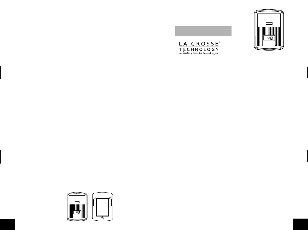
TX3U REMOTE CONTROL SENDER
The TX3 Remote control sender measures the outdoor temperature and
transmits the data to the Indoor Temperature Station.
REMOTE CONTROL
SENDER
Remote Control Sender Mounting Bracket
GB
P.2
433MHz
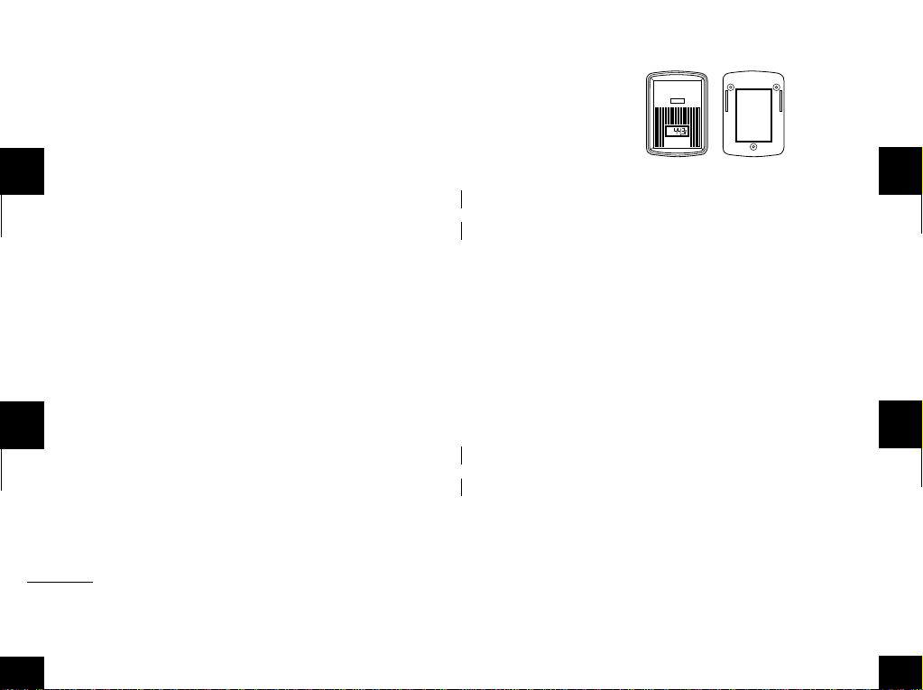
INVENTORY OF CONTENTS
1. The Remote Control Sender (RCS).
2. The Mounting Bracket.
3. Three each, 1/2" Philips mounting screws.
4. One strip double sided adhesive tape.
5. Instruction manual and warranty return card.
P.3
GB
Page 2

Note:
RCS’s will not usually read the same temperature as the y do abo ve .
This is due to variants such as drafts and handling. This is normal.
1. Install the batteries in sequential order. Obser ve the correct polarity
and install 2 AAA batteries. The batter ies will fit tightly-make sure they
do not spring free. This may cause start-up problems.
2. Check the LCD screen of the RCS for a temperature reading. If there is
no reading check the polarity of the batteries or replace with new
GB P.8
batteries.
3. Make sure the rubber weather seal is in place and replace the battery
cover, screw, and mounting bracket.
4. Observing the correct polarity, install 2 AA batteries into the Indoor
Temperature Station.
5. Replace battery cover.
6. Wait 5-6 minutes or until both indoor and outdoor temperatures are shown
on the LCD of the Indoor Temperature Station.
P.9
GB
7. The Indoor Temperature Station should now show “-:—” in the TIME
LCD, and temperatures in the INDOOR and OUTDOOR LCD’S.
II. MOUNTING
Note:
The sending range of the RCS is 80 ft. However, obstacles such as
walls, concrete, and large metal objects can reduce the range. Before
permanently mounting, place units in their desired location to see if a reading
is obtained. There should be a change of temperature in the OUTDOOR
P.10
GB
A. MOUNTING WITH THE SCREWS
1. Remove the mounting bracket from the RCS.
2. Place mounting bracket over desired location. Through the 3 scre w holes
of the bracket, mark the mounting surface with a pencil.
3. Where marked, drill holes into mounting surface using an appropriate
size drill bit.
4. Screw mounting bracket onto the mounting surface. Ensure that the
screws are flush with the bracket.
LCD within 6 minutes. If the Indoor Temperature Station loses the signal
from the RCS, it will display the last temperature reading for 15 minutes.
After 15 minutes of not receiving any signals the OUTDOOR LCD of the
Indoor Temperature Station will display “- - . -”. Also, ensure that the probe
can reach the desired location before mounting.
The RCS can be mounted in two ways:
• with the use of screws or,
• using the adhesive tape.
P.11
5. Snap the RCS into place, and situate the probe. It may be necessary to
further secure the probe and wire, to prevent drifting.
B. MOUNTING WITH ADHESIVE TAPE
1. With a nonabrasive solution, clean and dry the back of the mounting
bracket and the mounting surface to ensure a secure hold. The mounting
surface should be smooth and flat.
2. Remove the protective strip from one side of the tape. Press firmly into
GB P.12 GBP.13
GB
Page 3

3. The specifications of this product may change without prior notice.
4. This product is not a toy. Keep out of children’s reach.
5. No part of this manual may be reproduced without written consent of
the manufacturer.
VI. W ARRANTY INFORMATION
La Crosse Technology, Ltd provides a 1-year limited w arranty on this product
against manufacturing defects in materials and workmanship.
P.18
GB
This limited warranty begins on the original date of purchase, is valid only
on products purchased and used in North America and only to the original
purchaser of this product. To receive warranty service, the purchaser must
contact La Crosse Technology, Ltd for problem determination and service
procedures. Warranty service can only be performed by a La Crosse
Technology, Ltd authorized service center. The original dated bill of sale
must be presented upon request as proof of purchase to La Crosse
Technology, Ltd or La Crosse Technology, Ltd’s authorized service center.
P.19
GB
La Crosse Technology, Ltd will repair or replace this product, at our option
and at no charge as stipulated herein, with new or reconditioned parts or
products if found to be defective during the limited warranty period specified
above. All replaced parts and products become the property of La Crosse
Technology, Ltd and must be returned to La Crosse Technology, Ltd.
Replacement parts and products assume the remaining original warranty,
or ninety (90) days, whichever is longer. La Crosse Technology, Ltd will
P.20
GB
Your La Crosse Technology, Ltd warranty covers all defects in material and
workmanship with the following specified exceptions: (1) damage caused
by accident, unreasonable use or neglect (including the lack of reasonable
and necessary maintenance); (2) damage occurring during shipment (claims
must be presented to the carrier); (3) damage to, or deterioration of, any
accessory or decorative surface; (4) damage resulting from failure to follow
instructions contained in your owner’s manual; (5) damage resulting from
the performance of repairs or alterations by someone other than an
GB
P.22
pay all expenses for labor and materials for all repairs covered by this
warranty. If necessary repairs are not covered by this warranty, or if a
product is examined which is not in need or repair, you will be charged for
the repairs or examination. The owner must pay any shipping charges
incurred in getting your La Crosse Technology, Ltd product to a La Crosse
Technology, Ltd authorized service center. La Crosse Technology, Ltd will
pay reasonable return shipping charges to the owner of the product.
P.21
authorized La Crosse Technology, Ltd authorized service center; (6) units
used for other than home use (7) applications and uses that this product
was not intended or (8) the products inability to receive a signal due to any
source of interference. This warranty covers only actual defects within the
product itself, and does not cover the cost of installation or removal from a
fixed installation, normal set-up or adjustments, claims based on
misrepresentation by the seller or performance variations resulting from
installation-related circumstances.
P.23
GB
GB
Page 4
or chemical procedures without written permission of the publisher.
REMOTE CONTROL
SENDER
433MHz
This handbook may contain mistakes and printing errors. The information
in this handbook is regularly checked and corrections made in the next
issue. We accept no liability for technical mistakes or printing errors, or
their consequences.
All trademarks and patents are acknowledged.
GB
P.28
EMETTEUR A DISTANCE TX3U
L’ emetteur à distance TX3U mesure la température extérieure et
transmet les données au poste de température intérieur.
Emetteur à distance Support de montage
P.29
F
DESCRIPTION DU CONTENU
1. Emetteur à distance (RCS)
2. Support de montage
3. Trois vis cruciformes 1/2"
4. Un ruban adhésif double-face
5. Livret d’instructions et carte de garantie à renvoyer
P.30
F
quelle température, provenant de quel RCS, est affichée sur le poste de
température intérieur.
Remarque:
Retirer les piles de tous les appareils en opération - y
compris les appareils RCS et les postes de température intérieurs. Lors
du paramètrage de plusieurs appareils, il est important de commencer
par installer les piles dans tous les RCS, en séquence numérique.
Installer ensuite les piles dans le poste de température intérieur. Des
P.32
F
EQUIPEMENT COMPLEMENTAIRE (non inclus)
1. Un tournevis cruciforme
2. Un tournevis plat
3. Deux piles AAA, LR3, 1,5V neuves
I. PARAMETRAGE
Avant toute chose, commencer par attribuer un numéro à chaque RCS
(par ex. #1 pour l’extérieur, #2 pour la cave, etc.). ce qui permet de savoir
P.31
problèmes de transmission se produiront en cas de mise en place
incorrecte des piles ou si le temps total de paramètrage excède 6
minutes.
A. MISE EN PLACE DES PILES
Suivre les indications suivantes en cas de paramètrage des appareils,
remplacement des piles ou réenclenchement.
P.33
F
F
Page 5

et extérieures s’affichent sur le LCD du poste de température
intérieur.
10.Le poste de température intérieur devrait maintenant afficher “-:—” sur
le LCD de l’HEURE et les températures sur les LCD INTERIEUR et
EXTERIEUR.
II. MISE EN PLACE
Remarque :
Le rayon d’émission du RCS est de 25 m. Cependant, des
F P.38 F
obstacles tels que murs, béton et gros objets métalliques peuvent en
diminuer la portée. Avant d’installer les appareils de façon permanente,
s’assurer que les relevés sont possibles. Un changement de la
température sur le LCD EXTERIEUR devrait se produire dans les 6
minutes. Si le poste de température intérieur perd le signal du RCS, il
affiche la dernière température pendant 15 minutes. Après 15 minutes
sans réception d’aucun signal, le LCD EXTERIEUR du poste de
température intérieur affichera “—”. Avant de mettre les appareils en
P.39
place, s’assurer aussi que la sonde peut atteindre l’emplacement désiré.
Le RCS peut être installé de deux façons:
• avec les vis, ou,
• avec le ruban adhésif.
A. MISE EN PLACE AVEC LES VIS
1. Retirer le support de montage du RCS.
F
P.40
B. MISE EN PLACE AVEC LA BANDE ADHESIVE
1. A l’aide d’un produit non abrasif, nettoyer et sècher le dos du support
et la surface de montage afin d’assurer une bonne prise. La surface
de montage doit être lisse et plate.
2. Retirer la pellicule de protection d’un des côtés de la bande et
appliquer fermement cette dernière à l’endroit indiqué au dos du
support.
P.42
F
2. Placer le support de montage à l’emplacement désiré. A l’aide d’un
crayon, marquer les 3 trous de vis du support sur la surface de
montage.
3. A l’endroit indiqué, percer des trous avec une mèche appropriée.
4. Visser le support sur la surface de montage. S’assurer que les vis
sont bien serrées.
5. Fixer le RCS sur le support de montage.
P.41
3. Retirer la pellicule de protection de l’autre côté du ruban et mettre le
RCS en place à l’endroit désiré.
III. ENTRETIEN
1. Eviter les températures excessives, vibrations et chocs qui
endommageraient l’appareil.
2. Nettoyer affichages et appareils avec un chiffon doux et humide. Ne
pas utiliser de produits dissolvants ou abrasifs qui risquent de
marquer affichages et boîtiers.
P.43
F
F
Page 6

VI. CONTACT
La Crosse Technology, Ltd garantit ce produit de façon limitée pendant 1
an contre les défauts de fabrication et de matière.
Cette garantie limitée commence le jour du premier achat, n’est valable
que pour les produits achetés et utilisés en Amérique du Nord et ne
couvre que l’acheteur originel de ce produit. Pour toute intervention sous
garantie, l’acheteur doit contacter La Crosse Technology, Ltd pour
F P.48 F
l’identification du problème et les procédures de SAV. Les interventions
sous garantie ne peuvent être effectuées que dans un centre de SAV
agréé par La Crosse Technology, Ltd. Le ticket de caisse d’origine doit
être présenté sur demande à La Crosse Technology, Ltd ou à son centre
de SAV comme preuve d’achat.
La Crosse Technology, Ltd réparera ou remplacera, à notre discrétion, ce
produit gratuitement comme spécifié par la présente avec ou par des
P.49
pièces ou produits neufs ou remis à neuf si ce produit s’avère être
défectueux pendant la période de la garantie limitée exposée ci-dessus.
Toutes les pièces et produits remplacés deviennent la propriété de La
Crosse Technology, Ltd et doivent être restitués à La Crosse Technology,
Ltd. Les pièces et produits de rechange sont couverts par la garantie
d’origine restante ou pendant quatre-vingt-dix (90) jours, soit la durée la
plus longue. La Crosse Technology, Ltd prendra en charge tous les frais
de main d’œuvre et de matériels pour toute réparation couverte par cette
F
P.50
Votre garantie La Crosse Technology, Ltd couvre tous les défauts de
matières et de fabrication exceptés : (1) les dégâts causés par les
accidents, une utilisation déraisonnable ou négligence (y compris un
manque d’entretien raisonnable et nécessaire) ; (2) les dégâts survenant
pendant le transport (toute réclamation doit être faite au transporteur) ;
(3) dégâts à, ou détérioration de, tout accessoire ou toute surface
décorative ; (4) dégâts dus à un manquement aux instructions contenues
dans votre manuel de l’utilisateur ; (5) dégâts occasionnés suite à une
P.52
F
garantie. Si les réparations nécessaires ne sont pas couvertes par cette
garantie ou s’il s’avère, lors de sa vérification, qu’un produit ne nécessite
aucune réparation, la réparation ou vérification vous sera facturée. Le
propriétaire doit prendre en charge tous frais d’expédition du produit La
Crosse Technology, Ltd vers le centre de SAV agréé La Crosse
Technology, Ltd. La Crosse Technology, Ltd prendra en charge les frais
raisonnables de retour au propriétaire du produit.
P.51
réparation ou modification effectuée par un intervenant autre qu’un
centre de SAV agréé La Crosse Technology, Ltd ; (6) appareil utilisés
pour un usage autre que domestique (7) les applications et usages
auxquels cet appareil n’est pas destiné ou (8) l’incapacité du produit à
recevoir un signal à cause d’une source d’interférences quelconque.
Cette garantie ne couvre que les défauts du produit lui-même et ne
couvre pas les frais d’installation ou de désinstallation d’une installation
fixe, le paramétrage normal ou les réglages, les litiges basés sur les
P.53
F
F
Page 7

www.lacrossetechnology.com
site web :
Tous droits réservés. Ce manuel ne peut être ni reproduit sous quelque
forme que ce soit, même sous forme d’extraits, ni copié, ni traité par
procédure électronique, mécanique ou chimique, sans l’accord écrit de
l’éditeur.
Ce manuel peut contenir des erreurs et fautes d’impression. Les
informations contenues dans ce manuel sont régulièrement vérifiées, les
corrections étant apportées à l’édition suivante. Nous n’acceptons
aucune responsabilité pour les erreurs techniques ou d’impression ou
pour leurs conséquences.
Toutes les marques commerciales et brevets sont reconnus.
F P.58 F
TX3U TRANSMISOR A CONTROL REMOTO
El TX3U Transmisor a control remoto medida la temperatura al air libre y
P.59
transmita los datos a la Estación de Temperatura en Interiores.
Transmisor a Control Remoto
SENDER
433MHz
Soporte para colgario
INVENTARIO DE CONTENIDOS
1. Transmisor a control remoto (RCS).
REMOTE CONTROL
2. Soporte para colgarlo.
3. Tres tornillos o clavos “Philips” para colgar cada uno de 1/2".
S
P.60
4. Una tira de cinta adhesiva de doble faz.
3. Dos pilas nuevas AAA, 1.5V.
P.61
5. Manual de instrucciones y tarjeta de garantía retornable para la
garantía.
I. PONIENDO EN FUNCIONAMIENTO
Antes de que usted empiece, asígnele un número a cada RCS (ej. #1
EQUIPO ADICIONAL (no incluido)
1. Un destornillador Phillips
2. Un destornillador plano.
P.62
S
para el campo al aire libre, #2 para el sótano, etc.). Esto le ayudará a
determinar qué temperatura y de que RCS, es la que usted está leyendo
en la Estación de Temperatura en Interiores.
P.63
S
S
Page 8

Nota:
Los RCS normalmente no leerán la misma temperatura como lo
hacian anteriormente. Esto es debido a las variantes tales como pruebas
y posición donde se cuelge. Esto es normal.
4. Observe la polaridad correcta e instale 2 baterías de AAA en orden
secuencial. Las baterías encajarán y deben quedar precisasasegúrese de que estas no queden sueltas y sin hacer contacto.
Esto puede causar problemas en la iniciación de la puesta en
marcha.
S P.68 S
5. Verifique que las pantallas LCD de los RCS reciban la lectura de
temperatura. Si no hay ninguna lectura, cheque la polaridad de las
baterías o reemplázelas con nuevas baterías.
6. Asegúrese de que la estampilla de caucho del estado del tiempo este
en su sitio y vuelva a colocar las tapas de las pilas, tornillos, y
soportes para el montaje.
7. Observando la polaridad correcta, instale 2 pilas AA en la Estación de
Temperatura en Interiores.
P.69
8. Vuelva a colocar la tapa de las pilas.
9. Espere 5-6 minutos o hasta que las temperaturas en interiores y al
aire libre se muestren en el LCD de la Estación de Temperatura en
Interiores.
10.La Estación de Temperatura en Interiores debe mostrar ahora “-:—”
en la pantalla de la hora TIME LCD, y temperaturas en las pantallas
LCD INTERIOR y AL AIRE LIBRE (indoor/outdoor).
S
P.70
durante 15 minutos. Después de 15 minutos de no recibir ningúna señal
el LCD AL AIRE LIBRE de la Estación de Temperatura en Interiores
visualizará “- -. -”. También, asegúrese de que la sonda puede alcanzar
hasta la ubicación deseada antes de montar.
El RCS puede montarse de dos maneras:
• con el uso de tornillos o,
• usando la cinta adhesiva.
P.72
S
II. INSTLACION EN LA PARED
Nota:
El rango o área de transmisión del RCS es 80 pies. Sin embargo,
obstáculos como paredes, concretos, y los objetos metálicos grandes
pueden reducir este rango. Antes de montar las unidades
permanentemente colóquelas en el lugar deseado para ver si reciben la
lectura. Debe haber un cambio de temperatura en el LCD AL AIRE
LIBRE dentro de 6 minutos. Si la Estación de Temperatura en Interiores
pierde la señal del RCS, esta visualizará la última temperatura registrada
P.71
A. MONTANDO O INSTALANDO CON LOS TORNILLOS
1. Quite la abrazadera o soporte de montaje del RCS.
2. Ponga la abrazadera de montaje sobre la situación deseada. A través
de los 3 agujeros de los tornillos del soporte, marque la superficie de
la montura con un lápiz.
3. Donde haya marcado, taladre los agujeros en la superficie marcada
para montar, use una puntilla de taladro del tamaño apropiado.
P.73
S
S
Page 9

Intervalo de la transmisión
Frecuencia de la transmisión 433.92 MHz
Extensión de transmisión 80 pies (25m)
Fuente de Energía 2 pilas 2 x 1.5V AAA, IEC LR3,
Dimensiones 2.20” x 0.94” x 3.14”. (56 x 24 x 80 mm)
cada 10 segundos en los 3 primeros minutos,
cada 1 minuto después de esto
S P.78 S
V. PERDIDA DE LA GARANTIA
1. El fabricante y el proveedor no pueden aceptar ninguna
responsabilidad por cualquier lectura incorrecta y cualquier
consecuencia que pudiese ocurrir por una toma o lectura inexacta.
2. Este producto no deberá ser usado para propósitos médicos o para
información pública.
3. Las característica técnicas de este producto pueden cambiar sin
previo aviso.
P.79
4. Este producto no es un juguete. Manténgalo fuera del alcance de los
niños.
5. Ninguna parte de este manual puede reproducirse sin consentimiento
por escrito del fabricante.
VI. INFORMACION DE LA GARANTIA
La Crosse Technology, Ltd. le otorga para este producto una garantía
limitada por 1 año contra daños de fabricación y los materiales.
S
P.80
prueba de la compra por La Crosse Technology, Ltd o el centro de
servicio autorizado de La Crosse Technology.
La Crosse Technology, Ltd le reparará o le remplazará este producto,
bajo nuestra discreción y se hará gratuitamente tal como esta estipulado
en la presente, con piezas o productos nuevos o reparados si se
encuentran que estos son defectuosas durante el periodo cubierto por la
garantía limitada especificado anteriormente. Todas las piezas y
P.82
S
Esta garantía limitada comienza a partir del día de la compra, solamente
es valida para productos comprados en América del Norte y solamente
comprados al distribuidor original autorizado de este producto. Para
recibir servicio de la garantía, el comprador deberá contactar a La
Crosse Technology, Ltd para la evaluación de problemas y los tramites
de servicio. Los servicios de la garantía deberán ser hechos por el
centro autorizado de servicio al cliente de La Crosse Technology, Ltd. El
recibo original de compra deberá ser incluido si este solicitado como
P.81
productos cambiados pasarán a ser propiedad de La Crosse Technology,
Ltd y deberán ser devueltas a La Crosse Technology, Ltd. Las piezas o
productos cambiados seguirán cubiertos por la garantía original restante
del producto, o noventa (90) días, será lo que tenga mayor duración. La
Crosse Technology, Ltd pagará los gastos de mano de obra y materiales
de todas las reparaciones cubiertas por esta garantía. Si hay alguna
reparación necesaria que no este cubierta por esta garantía o si el
producto es examinado y no necesita ninguna reparación el costo de la
P.83
S
S
Page 10

O PARA INFORMACION AL PÚBLICO. ESTE PRODUCTO NO ES UN
JUGUETE. MANTÉNGALO FUERA DEL ALCANCE DE LOS NIÑOS.
Esta garantía le confiere derechos legales específicos. Usted también
puede tener otros derechos específicos de su Estado. Algunos Estados
no permiten la exclusión de daños y perjuicios consecuenciales o
incidentales, por lo tanto la anterior exclusión de limitación puede que no
aplique en su caso.
S P.88 S
Page 11

WARRANTY INFORMATION
La Crosse Technology, Ltd provides a 1-year limited warranty on this
product against manufacturing defects in materials and workmanship.
This limited warranty begins on the original date of purchase, is valid
only on products purchased and used in North America and only to
the original purchaser of this product. To receive warranty service,
the purchaser must contact La Crosse Technology, Ltd for problem
determination and service procedures. Warranty service can only be
performed by a La Crosse Technology, Ltd authorized service center.
The original dated bill of sale must be presented upon request as
proof of purchase to La Crosse Technology, Ltd or La Crosse
Technology, Ltd’s authorized service center.
La Crosse Technology, Ltd will repair or replace this product, at our
option and at no charge as stipulated herein, with new or
reconditioned parts or products if found to be defective during the
limited warranty period specified above. All replaced parts and
products become the property of La Crosse Technology, Ltd and
must be returned to La Crosse Technology, Ltd. Replacement parts
and products assume the remaining original warranty, or ninety (90)
days, whichever is longer. La Crosse Technology, Ltd will pay all
expenses for labor and materials for all repairs covered by this
warranty. If necessary repairs are not covered by this warranty, or if
a product is examined which is not in need or repair, you will be
charged for the repairs or examination. The owner must pay any
shipping charges incurred in getting your La Crosse Technology, Ltd
product to a La Crosse Technology, Ltd authorized service center.
La Crosse Technology, Ltd will pay ground return shipping charges to
the owner of the product to a USA address only.
Your La Crosse Technology, Ltd warranty covers all defects in
material and workmanship with the following specified exceptions: (1)
damage caused by accident, unreasonable use or neglect (including
the lack of reasonable and necessary maintenance); (2) damage
occurring during shipment (claims must be presented to the carrier);
(3) damage to, or deterioration of, any accessory or decorative
surface; (4) damage resulting from failure to follow instructions
contained in your owner’s manual; (5) damage resulting from the
performance of repairs or alterations by someone other than an
authorized La Crosse Technology, Ltd authorized service center; (6)
units used for other than home use (7) applications and uses that this
product was not intended or (8) the products inability to receive a
signal due to any source of interference.. This warranty covers only
actual defects within the product itself, and does not cover the cost of
installation or removal from a fixed installation, normal set-up or
1
Page 12

adjustments, claims based on misrepresentation by the seller or
performance variations resulting from installation-related
circumstances.
LA CROSSE TECHNOLOGY, LTD WILL NOT ASSUME LIABILITY
FOR INCIDENTAL, CONSEQUENTIAL, PUNITIVE, OR OTHER
SIMILAR DAMAGES ASSOCIATED WITH THE OPERATION OR
MALFUNCTION OF THIS PRODUCT. THIS PRODUCT IS NOT TO
BE USED FOR MEDICAL PURPOSES OR FOR PUBLIC
INFORMATION. THIS PRODUCT IS NOT A TOY. KEEP OUT OF
CHILDREN’S REACH.
This warranty gives you specific legal rights. You may also have
other rights specific to your State. Some States do no allow the
exclusion of consequential or incidental damages therefore the above
exclusion of limitation may not apply to you.
For warranty work, technical support, or information contact:
La Crosse Technology, Ltd
2809 Losey Blvd S.
La Crosse, WI 54601
Phone: 608.782.1610
Fax: 608.796.1020
e-mail:
support@lacrossetechnology.com
(warranty work)
sales@lacrossetechnology.com
(information on other products)
web:
www.lacrossetechnology.com
2
Page 13

FCC DISCLAIMER
This device complies with part 15 of the FCC rules. Operation is
subject to the following two conditions:
(1) This device may not cause harmful interference.
(2) This device must accept any interference received,
including interference that may cause undesired
All rights reserved. This handbook must not be reproduced in any
form, even in excerpts, or duplicated or processed using electronic,
mechanical or chemical procedures without written permission of the
publisher.
This handbook may contain mistakes and printing errors. The
information in this handbook is regularly checked and corrections
made in the next issue. We accept no liability for technical mistakes
or printing errors, or their consequences.
All trademarks and patents are acknowledged.
operation.
La Crosse Technology
Made in China
3
 Loading...