

Page 1
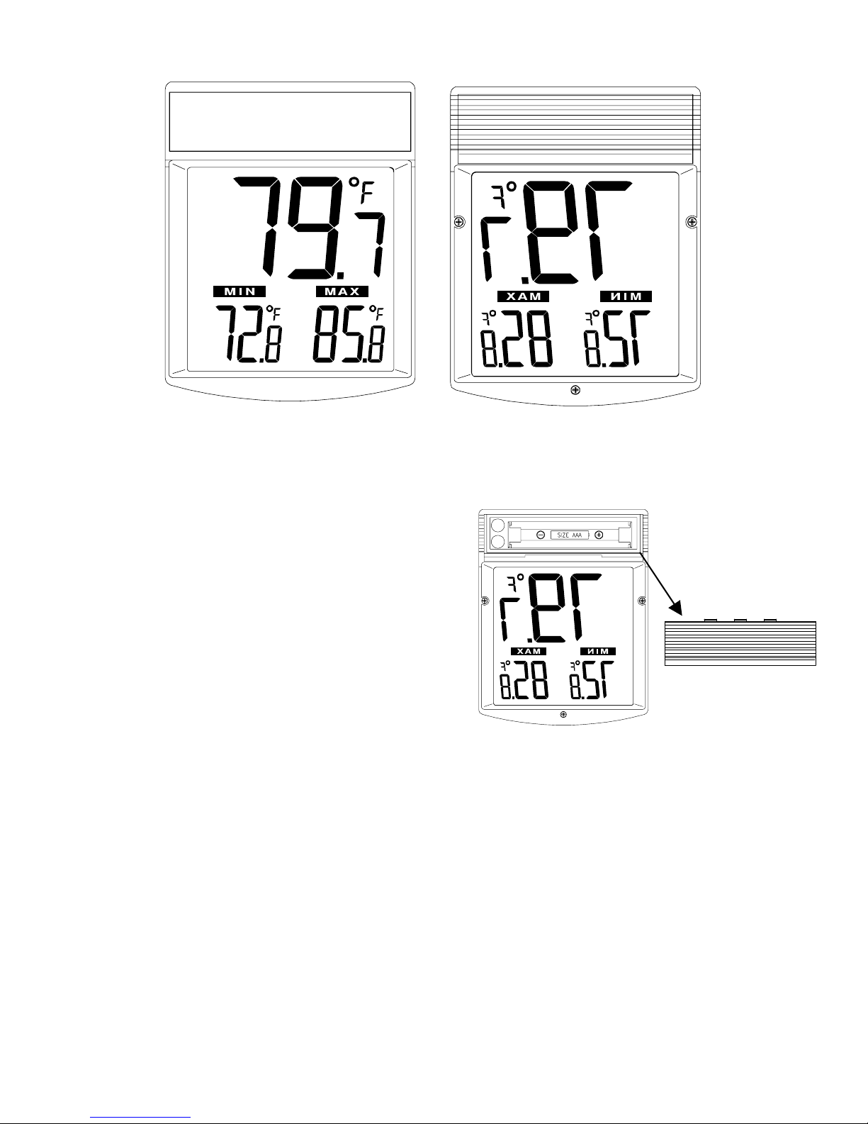
WT-62U Digital Window Thermometer
Features:
• Clear functional design
• Easy to read outdoor temperature from indoors
• Maximum and minimum values with auto reset
• Easy to mount
• Weather resistant
Specifications:
Measuring range: -22 ºF to +122 ºF
Resolution: 0.2 ºF
Temperature Updating Interval: Every 10 Seconds
Battery: 1 AAA
Inserting the Battery:
1. The battery cover is located on the back of the
thermometer.
2. Using your fingers slide the battery cover off of the battery compartment.
3. Observing the correct polarity insert one AAA battery into the battery compartment.
4. Replace the battery cover.
Setting the Time:
1. Press the MODE button to enter the setting mode.
2. The hours digits will flash in the center of the display.
3. Press and release the + button to advance the hour.
NOTE: When in the hours between midnight and noon, A.M. will be displayed on the left of the display. When in the
hours between noon and midnight P.M. will be displayed on the left side of the display.
4. Press and release the MODE button to confirm the hour and advance to the minute setting.
5. The minutes digits will flash at the bottom of the display.
6. Press and release the + button to advance the minute.
7. Holding down the + button will advance the minutes faster.
8. Press and release the MODE button to confirm the minutes and exit the time setting mode.
1
Page 2

NOTE: The thermometer will automatically time out and return to the normal display mode after approximately 30
seconds.
Installation:
1. Select your location for mounting in an area that is easy to view.
NOTE: The design of the thermometer is such that the display will appear
darker when looking at an upward angle at the display. It is recommended to
mount the thermometer slightly above eye level to ensure the best viewing of
the display.
2. Clean the glass surface completely before mounting.
NOTE: Be sure to completely clean the surface of dust and dirt and let the
area dry completely prior to mounting the thermometer. Failure to do
so may result in bad adhesion between the window and holder.
NOTE: Before continuing please be sure the time is set – See the previous
section on Setting the Time
3. Remove the plastic from the adhesive strip.
4. Press the adhesive strip against the glass to adhere the thermometer.
Please note: In order to obtain the most accurate temperature reading be
sure to mount the thermometer out of direct sunlight. Mounting the unit in
direct sunlight will cause artificially high temperature readings.
Use and MAX/MIN temperatures:
• The upper display shows the current temperature.
• The lower left display shows the minimum temperature.
• The lower right display shows the maximum temperature.
• The maximum temperature automatically resets at 8:00 A.M.
• The minimum temperature automatically resets at 8:00 P.M.
• If the time is not set the maximum and minimum temperature will not
be reset at the correct local time.
Maintenance:
• Replace the battery when the display becomes weak. * The low battery indicator will appear when the batteries
need to be changed.
• Do not expose the instrument to extreme temperatures, vibration or shock
• Clean the thermometer with a soft damp cloth only. Do not use solvents or scouring agents.
• Please do not try to repair the unit. Contact the original point of purchase or La Crosse Technology Warranty for
repair/ replacement instructions.
2
Page 3

WARRANTY INFORMATION
La Crosse Technology, Ltd provides a 1-year limited warranty on this product against manufacturing defects in materials and workmanship.
This limited warranty begins on the original date of purchase, is valid only on products purchased and used in North America and only to the original
purchaser of this product. To receive warranty service, the purchaser must contact La Crosse Technology, Ltd for problem determination and service
procedures. Warranty service can only be performed by a La Crosse Technology, Ltd authorized service center. The original dated bill of sale must be
presented upon request as proof of purchase to La Crosse Technology, Ltd or La Crosse Technology, Ltd’s authorized service center.
La Crosse Technology, Ltd will repair or replace this product, at our option and at no charge as stipulated herein, with new or reconditioned parts or
products if found to be defective during the limited warranty period specified above. All replaced parts and products become the property of La Crosse
Technology, Ltd and must be returned to La Crosse Technology, Ltd. Replacement parts and products assume the remaining original warranty, or
ninety (90) days, whichever is longer. La Crosse Technology, Ltd will pay all expenses for labor and materials for all repairs covered by this warranty. If
necessary repairs are not covered by this warranty, or if a product is examined which is not in need or repair, you will be charged for the repairs or
examination. The owner must pay any shipping charges incurred in getting your La Crosse Technology, Ltd product to a La Crosse Technology, Ltd
authorized service center. La Crosse Technology, Ltd will pay ground return shipping charges to the owner of the product to a USA address only.
Your La Crosse Technology, Ltd warranty covers all defects in material and workmanship with the following specified exceptions: (1) damage caused by
accident, unreasonable use or neglect (including the lack of reasonable and necessary maintenance); (2) damage occurring during shipment (claims
must be presented to the carrier); (3) damage to, or deterioration of, any accessory or decorative surface; (4) damage resulting from failure to follow
instructions contained in your owner’s manual; (5) damage resulting from the performance of repairs or alterations by someone other than an authorized
La Crosse Technology, Ltd authorized service center; (6) units used for other than home use (7) applications and uses that this product was not
intended or (8) the products inability to receive a signal due to any source of interference.. This warranty covers only actual defects within the product
itself, and does not cover the cost of installation or removal from a fixed installation, normal set-up or adjustments, claims based on misrepresentation by
the seller or performance variations resulting from installation-related circumstances.
LA CROSSE TECHNOLOGY, LTD WILL NOT ASSUME LIABILITY FOR INCIDENTAL, CONSEQUENTIAL, PUNITIVE, OR OTHER SIMILAR
DAMAGES ASSOCIATED WITH THE OPERATION OR MALFUNCTION OF THIS PRODUCT. THIS PRODUCT IS NOT TO BE USED FOR MEDICAL
PURPOSES OR FOR PUBLIC INFORMATION. THIS PRODUCT IS NOT A TOY. KEEP OUT OF CHILDREN’S REACH.
This warranty gives you specific legal rights. You may also have other rights specific to your State. Some States do no allow the exclusion of
consequential or incidental damages therefore the above exclusion of limitation may not apply to you.
For warranty work, technical support, or information contact:
All rights reserved. This handbook must not be reproduced in any form, even in excerpts, or duplicated or processed using electronic, mechanical or
chemical procedures without written permission of the publisher.
This handbook may contain mistakes and printing errors. The information in this handbook is regularly checked and corrections made in the next issue.
We accept no liability for technical mistakes or printing errors, or their consequences.
All trademarks and patents are acknowledged.
La Crosse Technology
2809 Losey Blvd. S.
La Crosse, WI 54601
Phone: 608.782.1610
Fax: 608.796.1020
e-mail:
(warranty work)
(information on other products)
web:
www.lacrossetechnology.com
3
Page 4
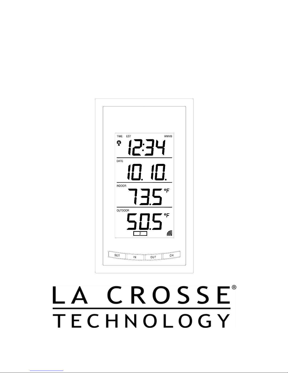
WS-9013U
Wireless 433 MHz
Radio-controlled Weather Station
Instruction Manual
Page 5
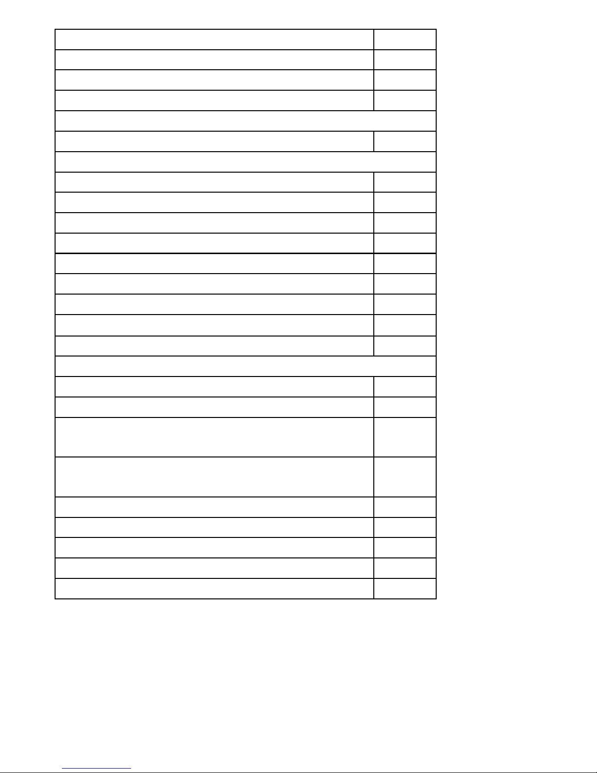
Topic Page
Inventory of Contents/Additional Equipment 3
About WWVB 4
Quick Set-Up Guide 5
Detailed Set-Up Guide
Battery Installation 6-7
Program Mode
Programming Sequence 7
Function Keys 8
12/24 Hour Time Setting 8
Time Zone Setting 8-9
Daylight Saving Time Setting 9-10
Time Setting (WWVB & Manual) 10-11
Setting Day, Date and Year 11-12
Selecting °F or °C
12
Setting the LCD Contrast 13
Features
Indoor Temperature 14
Outdoor Temperatures 14
Minimum & Maximum Records (Indoor,
15-16
Outdoor & Resetting)
Additional Remote Temperature Sensor
16-17
Table Of Contents
Units (Set-Up, Viewing & Operation)
Mounting 18-19
Troubleshooting 20
Maintenance & Care 20
Specifications 21
Warranty Information 22-23
2
Page 6
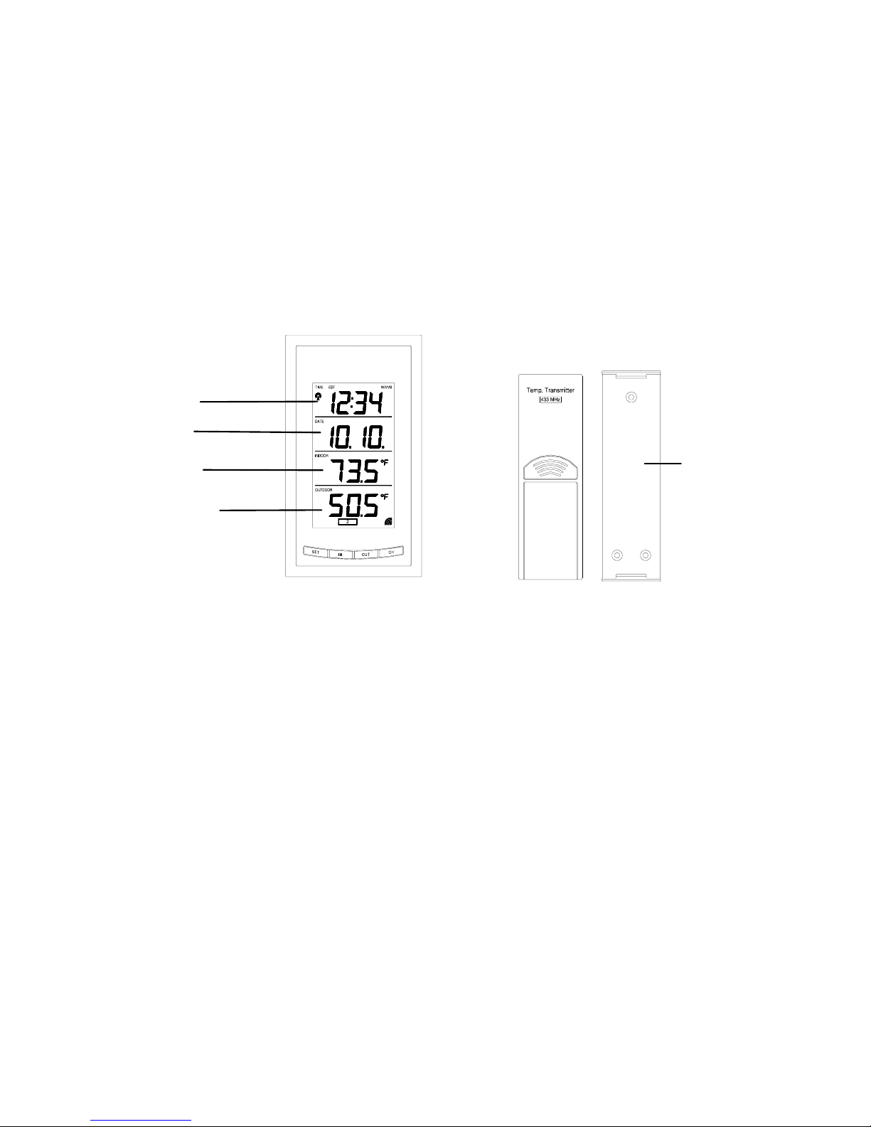
INVENTORY OF CONTENTS
1. The weather station (Figure 1).
2. One TX6U remote temperature sensor with mounting bracket
(Figure 2).
3. Three each, ½” Philips screws.
4. One strip double-sided adhesive tape.
5. Instruction Manual and Warranty Card.
Time LCD
Figure 1
ADDITIONAL EQUIPMENT (not included)
1. Two, fresh AA 1.5V batteries for indoor weather station.
2. Two, fresh AA 1.5V batteries for remoter temperature sensor.
3. One, Philips screwdriver for mounting.
Figure 2
Mounting
Bracket
3
Page 7

ABOUT WWVB (Radio Controlled Time)
The NIST (National Institute of Standards and Technology—Time and Frequency
Division) WWVB radio statio n is located in Ft. Collins, Colorado and transmits the
exact time signal continuously throughout the United States at 60 kHz. The signal
can be received up to 2, 000 miles away through the internal antenna in the weather
station. However, due to the nature of the earth’s ionosphere, reception is very
limited during daylight hours. The weather station will search for a signal every
night when reception is best. The WWVB radio station derives its signal from the
NIST Atomic clock in Boulder, Colorado. A team of atomic physicists is
continually measuring every second, of every day, to an accuracy of ten billionths of
a second per day. These physicists have created an international standard measuring
a second as 9,192,631,770 vibrations of a Cesium-133 atom in a vacuum.
For more information on WWVB and the atomic clock please see the NIST website
at http://www.boulder.nist.gov/timefreq/stations/wwvb.htm
.
4
Page 8

QUICK SET-UP GUIDE
Hint: Use good quality Alkaline Batteries and avoid rechargeable batteries.
1. Have the indoor weather station and remote temperature sensor 3 to 5
apart.
2. Batteries should be out of b oth units.
3. Place the batteries into the remote temperature sensor first then into
the indoor weather station.
(All remote temperature sensors must be started before the indoor
weather station)
4. DO NOT PRESS ANY BUTTONS FOR 15 MINUTES.
In this time the indoor weather station and remote temperature sensor will start to
talk to each other and the indoor weather station will show both the indoor
temperature and an outdoor temperature. If the indoor weather station does not
display both temperatures after the 15 minutes please retry the set up as stated above.
After both indoor and outdoor temperatures are displayed for 15 minutes you can
place your remote temperature sensor outdoors and set your time.
The remote temperature sensor should be placed in a dry, shaded area. The remote
temperature sensor has a range of 80 feet. An y walls that the signal will have to pass
through will reduce distance. An outdoor wall or window can have up to 30 feet of
resistance and an interior wall can have up to 20 feet of resistance depending upon
the type of construction. Your distance plus resistance should not exceed 80 ft. in a
straight line.
NOTE: Fog and mist will not harm your remote temperature sensor but direct rain
must be avoided.
To complete the set up of your indoor weather station after the 10 minutes have
passed please follow the steps on pages 8 and 9.
Note:
The remote temperature sensor transmits a signal every 3 minutes;
after the batteries have been installed, the indoor weather station will
search for the signal for a duration of 5 minutes. If there is no temperature
reading in the OUTDOOR LCD after 5 minutes, make sure the units are
within range of each other or repeat the battery installation procedure.
5
Page 9
DETAILED SET-UP GUIDE
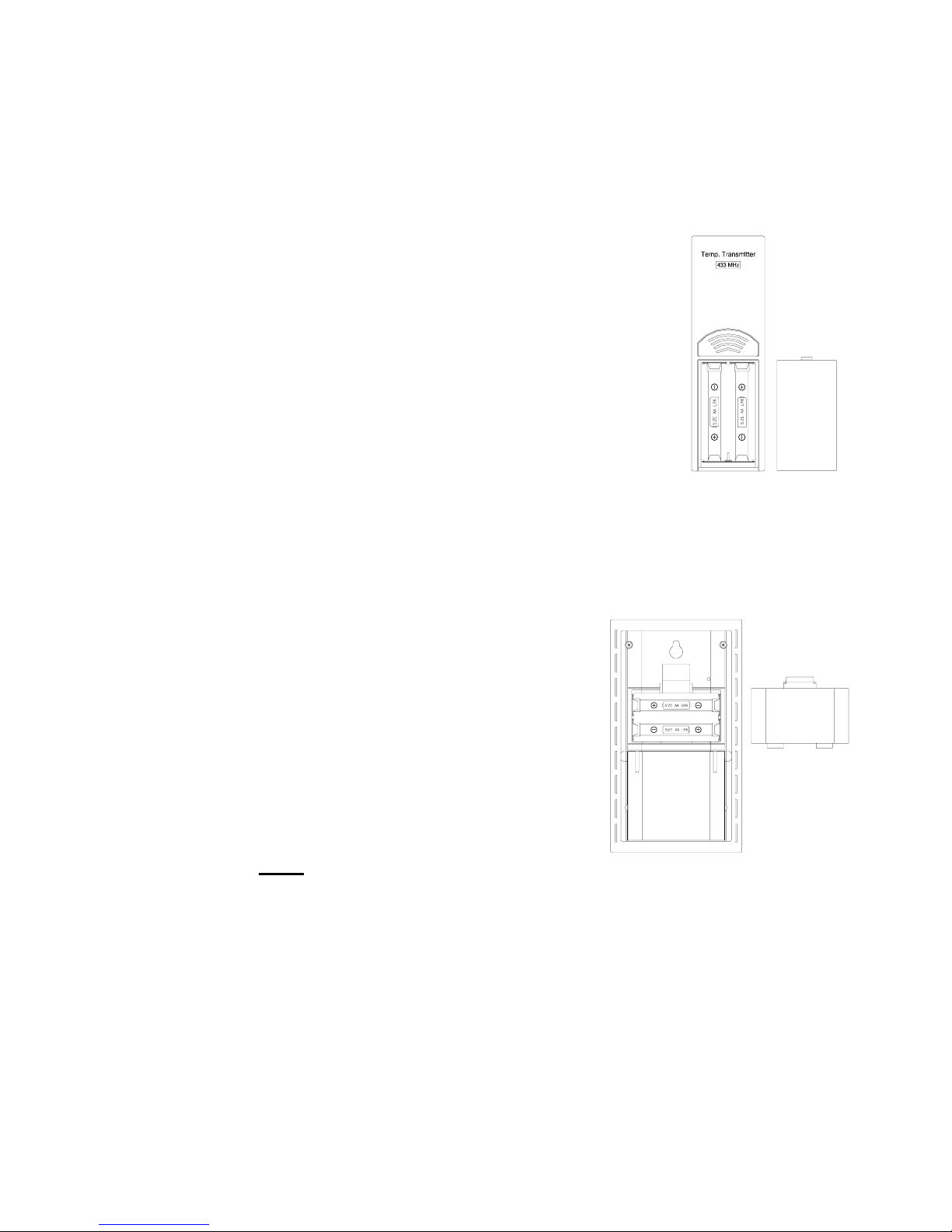
I. BATTERY INSTALLATION
A. REMOTE TEMPERATURE SENSOR
1. Remove the mounting bracket. The
bracket snaps on and off easily.
2. Remove the battery cover, by sliding the
cover down.
3. Observing the correct polarity install 2
AA batteries. The batteries will fit
tightly (to avoid start-up problems make
sure they do not spring free).
4. Replace the battery cover by sliding
upwards. Be sure battery cover is on
securely.
B. INDOOR WEATHER STATION
1. Remove the battery cover. To
do this, insert a solid object in
the space provided at the lowercentral position of the battery
cover, then push up and pull out
on the battery cover.
2. Observe the correct polarity,
and install 2 AA batteries.
3. Replace the battery cover.
Note: Immediately after the batteries
have been installed, each LCD (Liquid Crystal Display) will flash. Within
a few seconds the indoor temperature will be displayed. If not, then
remove the batteries for 10 seconds and reinstall. If the outdoor
temperature is not displayed within four minutes, remove batteries from
both units, wait 10 seconds, and reinstall. The time will show -:-- and
start searching for the WWVB signal. If it successfully receives the time
signal (usually at night), it will display the correct time (default is
Eastern).
Battery
Cover
6
Page 10

PROGRAM MODE
Programming Note:
the OUT button is pressed during progr amming modes, the unit will set the
last information entered—the display will stop flashing and return to
normal time-date readings. If you don’t leave the program mode during the
programming of sections III through VIII, you can advance to step 3 of the
next program setting. If you do leave the program setting (or want to
program a specific setting) follow each instructional step to program that
setting.
I. PROGRAMMING SEQUENCE
The sequence for programming the indoor weather station and the default
(factory) settings are:
1. 12/24 hour time setting 12 hour
2. Time Zone Zo -5 (eastern)
3. Daylight Saving Time 1 (on)
4. Time – hour 12
5. Time – minute 00
6. Date – day of the week mo (Monday)
7. Date – month 1 (January)
8. Date – day of the month 1
9. Date – Year 1999
If 30 seconds are allowed to pass or either the IN or
10. Temperature °F
11. LCD (liquid crystal display) contrast 5
12. End of sequence
The programming instructions are given in a manner so that each setting is
done separately. On initial set-up and after inserting new batteries to
program all functions simply disregard the first two steps of each section
starting with the Time Zone Setting.
7
Page 11
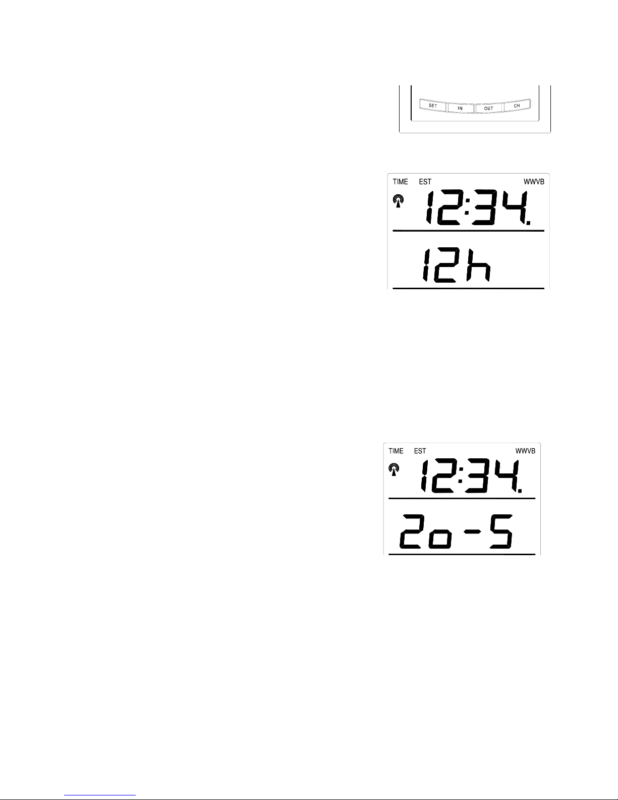
II. FUNCTION KEYS
The function keys are operated by pressing
the key corresponding to the operation that
you want to perform.
II. 12 OR 24 HOUR TIME SETTING
1. Press and hold the “SET”
button for 3 seconds or until
“12 h” flashes in the DATE
LCD.
2. Press and release the “CH”
button to toggle between 12
and 24-hour time.
3. Press and release the “SET” button to confirm the 12/24-hour
setting and to advance to Time Zone Setting.
III. TIME ZONE SETTING
The default time zone is EST, “Zo -5” (Eastern Standard Time), to
change this setting:
1. Press and hold the “SET” button for 3 seconds or until “12 h”
OR “24 h” flashes in the
DATE LCD.
2. Press and release the “SET”
button 1 more time to enter
the Time Zone setting mode.
3. The default Time Zone “Zo5” will flash in the DATE
LCD.
8
Page 12
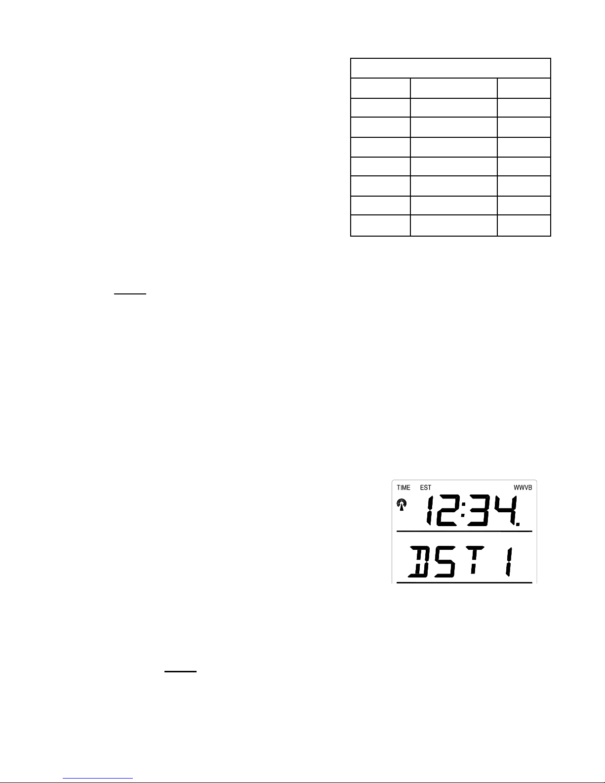
4. Select your appropriate
time zone using the
“CH” button. During
selection of the Time
Zone, the 3 letter
abbreviations for the time
GMT 0
Atlantic -4
EST; Eastern -5
CST; Central -6
Time Zones
zones found in North
America will flash across
the top of the TIME
LCD. Observe the chart
below, showing the
MST; Mountain -7
PST; Pacific -8
ALA; Alaska -9
HAW; Hawaii -10
corresponding
abbreviations, time zones, and codes.
Note:
There are more time zones represented by numbers than there are
represented by 3 letter abbreviations. If you live in North America you
need only be concerned with the ones in the chart above.
5. Press and release the “SET” button to confirm and advance to
the Daylight Saving Time setting.
IV. DAYLIGHT SAVING TIME (DST) SETTING
1. Press and hold the “SET” button for 3 seconds or until “12 h”
or “24 h” flashes in the DATE LCD.
2. Press and release the “SET” button 2 more times to reach the
DST selection mode.
3. “DST 1” is the default setting
and will be flashing in the
DATE LCD.
4. Press and release the “CH”
button to select “DST 0” or
“DST 1.”
5. “DST 0” indicates that the feature is o ff and the WWVB will
not change times automatically. “DST 1” indicates that the
feature is on and the WWVB will change times automatically.
Note:
Some locations (Arizona and parts of Indiana) do not
follow Daylight Saving Time and should select “DST 0.”
9
Page 13

6. Press and release the “SET” button to confirm and advance to
the Time setting mode.
V. TIME
There are two methods by which the time can be set:
A) Automatically via WWVB reception or
B) Manually.
A. WWVB (Remote Control Time)
This method requires you to do nothing except wait for the signal
to be received and to select a time zone. Reception usually takes
approximately 6-10 minutes during optimal conditions. The best
conditions for reception is at night, between midnight and 6:00
AM—when there is less atmospheric interference. To keep your
time as accurate as possible, the weather station conducts a
WWVB search every night between these hours and overrides any
manually set time. The WWVB tower icon (appearing in the TIME
LCD) will flash when a signal-search is in progress, will remain
steady when the signal has been received and nothing will be
displayed in all other situations. If the W WVB time has not been
received after 10 minutes of battery installation, you may manually
set the time or leave the time function alone (once reception has
occurred the WWVB time will over rid e the manual time and set
automatically).
B. MANUAL TIME SETTING
1. Press and hold the “SET” button for 3 seconds or until “12h”
flashes in the DATE LCD.
2. Press and release the “SET” button 3 more times.
3. The hour digit (default of “12” should be flashing in the
TIME LCD).
4. Press and release the “CH” button to change the hour. Press
the “CH” button once and the hour will increase by one,
twice and the hour will increase by tw o, etc.
10
Page 14
5. Press and release the “SET” button to confirm the hour
setting and to advance to the minute setting mode.
6. The minute digits should be flashing. Press and release the
"CH” button to change the minutes—increasing the minutes
by increments of 1 with each press of the “CH” button.
7. Press and release the “SET” button to confirm the minutes
and to advance to the Day, Date, and Year setting mode.
Note:
In 12h mode, “PM” will appear to the left of the time
during PM hours. If the time is not within the PM hours, nothing
will be displayed. Be sure to set the time to the correct AM/PM
time to ensure automatic reception at optimal times.
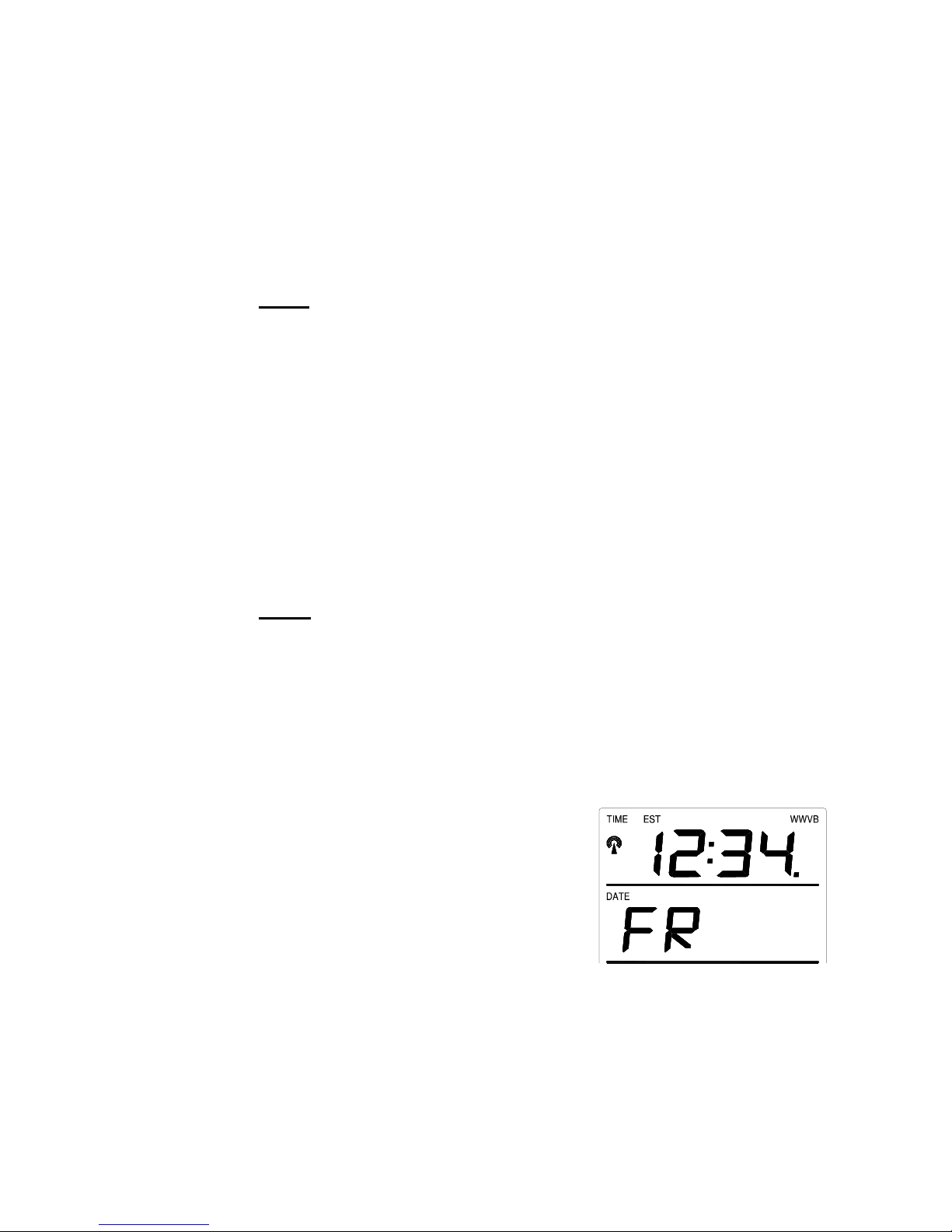
VI. SETTING THE DAY, DATE, AND YEAR
1. Press and hold the “SET” button for 3 seconds, or until “12 h”
or “24 h” flashes in the DATE LCD.
2. Press and release the “SET” button 5 more times to reach the
Weekday setting mode.
Note:
“MO” (representing Monday) is the default setting for the
weekday, “1.1” is the default setting for the numeric month and
day, and “1999” is the default setting for the year. The day, date,
and year will be automatically set once the WWVB signal is
received. However, the day, date, and year can be manually set
and will flash respectively in the DATE LCD during manual
programming.
3. The weekday will be
flashing in the DATE LCD,
press and release the “CH”
button to change the
weekday.
4. Press and release the “SET”
button to confirm, and to
enter the numeric-month setting mode.
11
Page 15
5. The numeric-month will be flashing in the DATE LCD. Press
and release the “CH” button to select to the current month.
6. Press and release the “SET” button to confirm the numeric-
month, and to enter the numeric-day setting mode.
7. The numeric-day will be flashing, press and release the “CH”
button to select the current day.
8. Press and release the “SET”
button to confirm and to enter
the year setting mode.
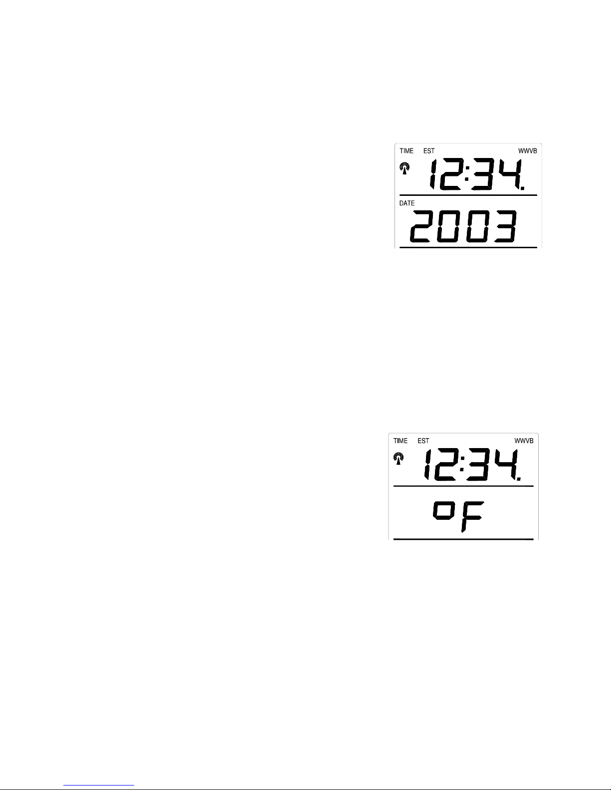
9. The default-year will be
flashing, press and release the
“CH” to select the appropriate
year.
10. Press and release the “SET” button to confirm and to advance
to the °F or °C setting mode.
VII. SELECTING °F OR °C
1. Press and hold the “SET” button for 3 seconds, or until “12h”
or “24h” flashes in the DATE LCD.
2. Press and release the “SET” button 9 times to reach the °F or
°C setting mode.
3. “°F” is the default setting, and
should be flashing in the
DATE LCD.
4. Press and release the “CH”
button to shift °F to °C and
back.
7. Press and release the “SET”
button to confirm your
selection and to advance to the LCD contrast setting.
12
Page 16
VIII. SETTING THE LCD CONTRAST
1. Press and hold the “SET” button for 3 seconds or until “12h”
or “24h” flashes in the DATE LCD.
2. Press and release the “SET” button 10 more times to reach the
LCD contrast setting mode.
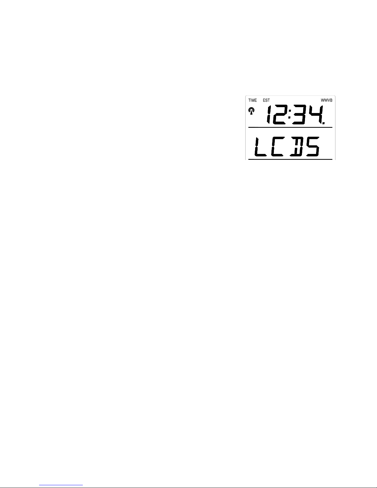
3. The default setting—“Lcd 5” will
flash in the DATE LCD.
4. There are 8 LCD contrast levels
to choose from—“Lcd 0” is the
lightest and “Lcd 7” is the
darkest.
5. Press and release the “CH”
button to toggle through the settings.
6. Press and release either the “IN” or “OUT” buttons to
confirm all the settings and to exit the manual-programming
mode (or wait 15 seconds for the unit to automatically return
to the normal display mode).
13
Page 17
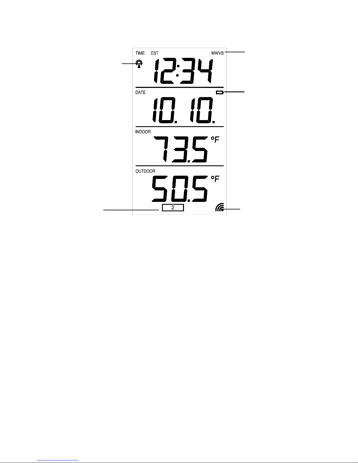
FEATURES OF THE WS-9013U
WWVB Tower Icon (indicates
Remote Temperature
Sensor Channel Indicator
I. INDOOR TEMPERATURE
The current indoor is displayed in the INDOOR LCD and is updated every
10 seconds.
II. OUTDOOR TEMPERATURE
The outdoor temperature is viewed in the OUTDOOR LCD. The outdoor
temperature is updated every five minutes. When there is more than one
remote temperature sensor unit in operation, a “boxed” number will appear
under the temperature. This indicates which remote temperature sensor unit
(1, 2, or 3) is currently displaying its data in the OUTDOOR LCD. (This
feature is explained in further detail in section VI—Adding Remote
Temperature Sensors).
WWVB Icon
(indicates Radiocontrolled time
Low Battery
Satellite icon (indicates
14
Page 18

III. MINIMUM AND MAXIMUM TEMPERATURE RECORDS
The WS-9013U keeps a record of the MINIMUM and MAXIMUM
temperature and the time and date of their occurrence—for both the indoor
and outdoor modes.
A. VIEWING THE INDOOR TEMPERATURE RECORDS
1. Press the “IN” button once. “MIN” appears in the upper
portion of the flashing INDOOR LCD indicating that the
minimum temperature and the time and date of occurrence are
displayed. The minimum records will display for 20 seconds.
2. Press the “IN” button again (once while “MIN” is still
displayed, twice otherwise). “MAX” appears in the upper
portion of the flashing INDOOR LCD indicating that the
maximum temperature and the time and date of occurrence are
displayed.
3. W h ile “MAX ” is still disp layed p ress th e “IN” button again to
return to the current data display. By waiting 20 seconds
during either the minimum or the maximum readings the unit
will automatically return to current data readings.
B. VIEWING THE OUTDOOR TEMPERATURE
RECORDS
1. Press the “OUT” button once. “MIN” appears in the upper
portion of the flashing OUTDOOR LCD, indicating that the
minimum temperature and the time and date of occurrence are
displayed. The minimum records will display for 20 seconds.
2. Press the “OUT” button again (once while “MIN” is still
displayed, twice otherwise). “MAX” appears in the upper
portion of the flashing OUTDOOR LCD, indicating that the
maximum temperature and the time and date of occurrence are
displayed.
3. W hile “MAX ” is still displayed press the “OUT” button again
to return to the current data display. By waiting 20 seconds
during either the minimum or the maximum readings the unit
will automatically return to current data readings.
15
Page 19

C. RESETTING THE MIMIMUM AND MAXIMUM
RECORDS
1. All the indoor record s (minimum and maximum) will be reset
after the “IN” button is pressed and held for 5 seconds.
2. All the outdoor records (minimum and maximum) will be
reset after the “OUT” button is pressed and held for 5
seconds.
IV. ADDING OUTDOOR REMOTE CONTROL SENDERS
(OPTIONAL)
The WS-9013U is able to receive signals from 3 different remote
temperature sensors. The remote temperature sensor model(s) that you
choose will come with their own set of instructions. Follow these
instructions for a complete guide to setting up. Following are some brief
instructions for the basic set-up of remote temperature senso r units with the
WS-9013U. These extra remote temperature sensors can be purchased
through the same dealer as this unit, or by contacting La Crosse Technology
directly. A TX6U will monitor temperature only, a TX3U will monitor
temperature and display the temperature on its LCD, and the TX3UP will
monitor the temperature via a probe for measuring soil or water
temperatures..
Note:
When setting up multiple u nits it is importan t to remove the batteries
from all existing units in operation. Then insert batteries into all the
remote temperature sensor units in numeric sequence. Second, install
batteries into the indoor weather station. Transmission problems will arise
if this is not done correctly and if the total time for set-up exceeds 6
minutes.
A. SET-UP OF MULTIPLE UNITS
1. It is necessary to remove the batteries from all units currently
in operation.
2. Remove the battery covers to all remote temperature sensor
units.
16
Page 20

3. Place all remote temperature sensor units in a numeric
sequential order.
4. In sequential order, install batteries (follow the same battery
installation procedures seen in section I. A) of the Detailed
Set-Up Guide).
5. Install batteries into the indoor weather station.
6. Follow the Detailed Set-Up Guide for programming and
operating instructions.
B. VIEWING AND OPERATING WITH MULTIPLE
REMOTE TEMPERATURE SENSOR UNITS
1. To view the temperature of a different remote temperature
sensor unit, press and release the “CH” button. A shift from
one “boxed” number to the next should be observed in the
OUTDOOR LCD.
2. To view the Minimum/Maximum temperature: first select
which remote temperature sensor to read data from (indicated
by the “boxed” number), then press and release the
“MIN/MAX” button. Pressing this button once will display
the minimum temperature and the date and time the data was
recorded. Pressing this button a second time (while “MIN” is
still displayed, otherwise press the button twice) will display
the same data for the maximum record ings.
3. To reset the Minimum/Maximum readings, it is necessary to
select which remote temperature sensor you wish to reset.
Press and hold the “OUT” button for 5 seconds, the records
for the selected remote temperature sensor unit will be reset.
17
Page 21

MOUNTING
Note:
is able to receive WWVB signals from the desired location. Also, extreme
and sudden changes in temperature will decrease the accuracy of the
indoor weather station. To achieve a true temperature reading, avoid
mounting where direct sunlight can reach the remote temperature sensor.
We recommend that you mount the remote temperature sensor on a Northfacing wall. The sending range is 80ft—obstacles such as walls, concrete
and large metal objects can reduce the range. Place both units in their
desired location and wait approximately 15 minutes before permanently
mounting to ensure that there is proper reception. The indoor weather
station should display a temperature in the OUTDOOR LCD within 4
minutes of setting up.
Before permanently mounting ensure that the indoor weather station
I. THE REMOTE TEMPERATURE SENSOR
The remote temperature sensor can be mounted in two ways:
• with the use of screws, or
• using the adhesive tape.
A. MOUNTING WITH SCREWS
1) Remove the mounting bracket from the remote
temperature sensor.
2) Place the mounting bracket over the desired location.
Through the three screw holes of the bracket, mark
the mounting surface with a pencil.
3) Where marked, start the screw holes into mounting
surface.
4) Screw mounting bracket onto the mounting surface.
Ensure that the screws are flush with the bracket.
B. MOUNTING WITH ADHESIVE TAPE
1) With a nonabrasive solution, clean and dry the back
of the mounting bracket and the mounting surface to
18
Page 22

ensure a secure hold. The mounting surface should
be smooth and flat.
2) Remove the protective strip from one side of the
tape. Adhere the tape to the designated area on the
back of the mounting bracket.
3) Remove the protective strip from the other side of the
tape. Position the remote temperature sensor in the
desired location, ensuring that the indoor temperature
station can receive the signal.
II. THE INDOOR TEMPERATURE STATION
The indoor temperature station can be mounted in two ways:
• with the table stand or
• on the wall with the use of a wall hanging screw (not
included).
A. USING THE TABLE STAND
1) The indoor temperature station comes with the table
stand already mounted. If you wish to use the tablestand all that is required is to place the indoor
temperature station in an appropriate lo cation.
B. WALL MOUNTING
1) Remove the table stand. To do this, pull down on the
stand from the rear and rotate forward.
2) Fix a screw (not included) into the desired wall leaving
approximately 3/16 of an inch (5mm) extended from
the wall.
3) Place the indoor temperature station onto the screw
using the hanging hole on the backside. Gently pull
the station down to lock the screw into place.
19
Page 23

TROUBLESHOOTING
Problem: No reception of WWVB time signal.
Solution: 1) Wait overnight for signal.
2) Be sure indoor weather station is at least 6 feet from any electrical
devices such as televisions, computers or other radio-controlled clocks.
3) Remove batteries for five minutes, reinsert and leave the unit alone
overnight without pressing buttons.
4) If there are still problems, contact La Crosse Technology.
Problem: Hour is incorrect (minute and date are correct).
Solution: Be sure correct time zone and daylight saving time is selected.
Problem: The LCD is faint
Solution: 1) Set the LCD contrast to a higher number
2) Replace batteries
Problem: No outdoor temperature is displayed.
Solution: 1) Remove all batteries, reinsert into remote temperature sensor first, then
into the indoor temperature station.
2) Place remote temperature sensor closer to the indoor temperature
station.
3) Be sure all batteries are fresh.
NOTE: For problems not solved, please contact La Crosse Technology.
MAINTENANCE AND CARE INSTRUCTIONS
• Extreme temperatures, vibration and shock should be avoided to prevent
damage to the units.
• Clean displays and units with a soft, damp cloth. Do not use solvents or
scouring agents. They may mark the displays and casings.
• Do not submerge in water.
• Immediately remove all low powered batteries to avoid leakage and
damage.
20
Page 24
• Opening the casings invalid ates the warranty. Do not try to repair the unit.
Contact La Crosse Technology for repairs.
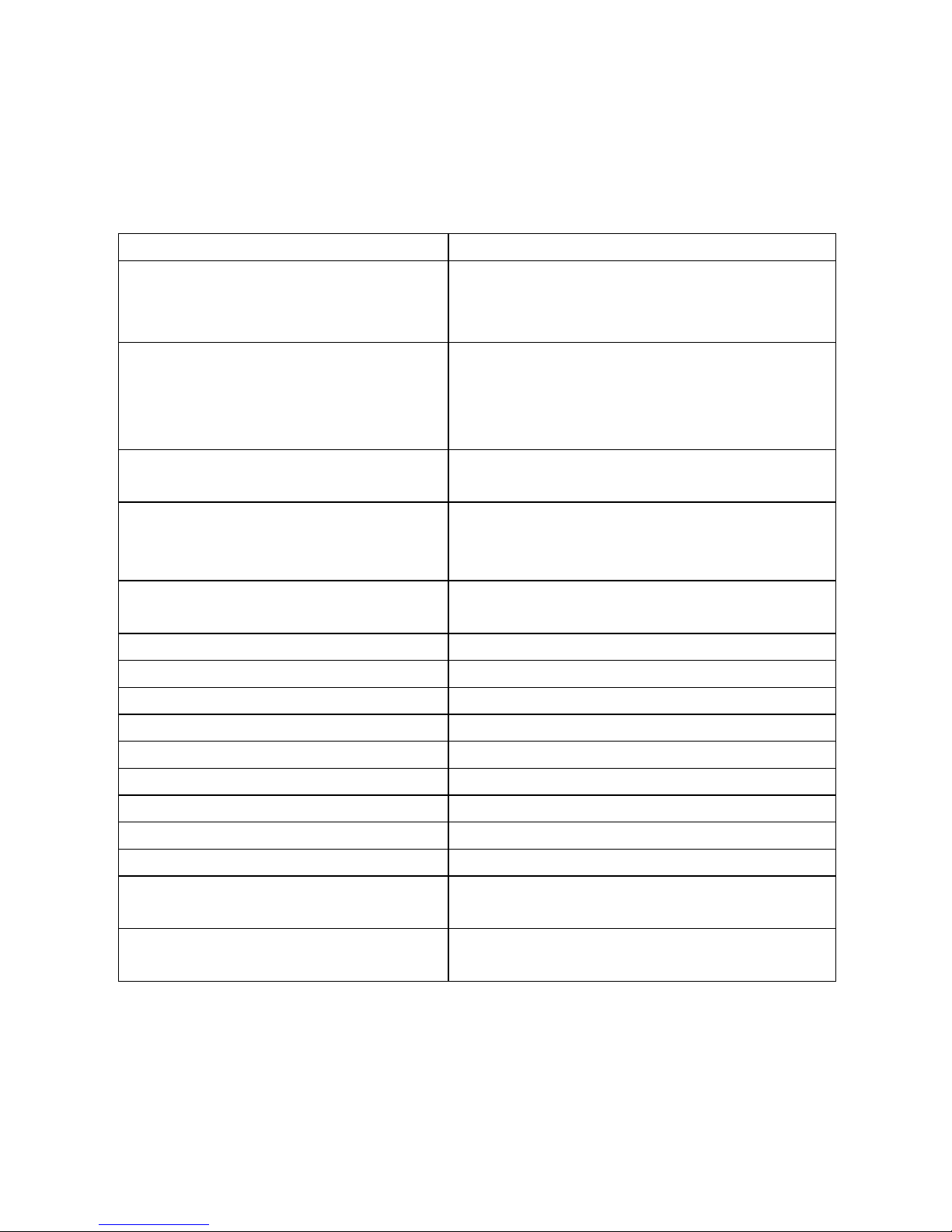
SPECIFICATIONS
Temperature measuring range:
Indoor:
32°F to 139.8°F with 0.2°F resolution.
(0°C to 59.9°C with 0.1°C resolutio n)
“OFL” displayed if outside this range
Outdoor:
-21.8°F to 157.2°F with 0.2°F
resolution.
(-29.9°C to 69.9°C resolution) “OFL”
displayed if outside this range
Indoor temperature checking
Every 10 seconds
interval:
Outdoor temperature checking
Every 1 minute
interval:
(Remote Temperature Sensor)
Outdoor temperature reception:
Every 5 minutes
(Indoor Weather Station)
Transmission Range: 80 feet (in open space)
Power Supply:
Indoor Weather Station: 2 x AA, IEC LR6, 1.5V
Remote Temperature Sensor: 2 x AA, IEC LR6, 1.5V
Battery life cycle: Approximately 12 months
Recommended battery type: Alkaline
Dimensions (H x W x D)
Indoor Weather Station: 5.5” x 3.2” x 1.25”
(140 x 81 x 32 mm)
Remote Temperature Sensor: 5.04” x 1.57” x 0.9”
(128 x 40 x 23 mm)
21
Page 25

WARRANTY INFORMATION
La Crosse Technology, Ltd provides a 1-year limited warranty on this product against
manufacturing defects in materials and workmanship.
This limited warranty begins on the original date of purchase, is valid only on products
purchased and used in North America and only to the original purchaser of this
product. To receive warranty service, the purchaser must contact La Crosse
Technology, Ltd for problem determination and service procedures. Warranty service
can only be performed by a La Crosse Technology, Ltd authorized service center.
The original dated bill of sale must be presented upon request as proof of purchase to
La Crosse Technology, Ltd or La Crosse Technology, Ltd’s authorized service center.
La Crosse Technology, Ltd will repair or replace this product, at our option and at no
charge as stipulated herein, with new or reconditioned parts or products if found to be
defective during the limited warranty period specified above. All replaced parts and
products become the property of La Crosse Technology, Ltd and must be returned to
La Crosse Technology, Ltd. Replacement parts and products assume the remaining
original warranty, or ninety (90) days, whichever is longer. La Crosse Technology, Ltd
will pay all expenses for labor and materials for all repairs covered by this warranty. If
necessary repairs are not covered by this warranty, or if a product is examined which
is not in need or repair, you will be charged for the repairs or examination. The owner
must pay any shipping charges incurred in getting your La Crosse Technology, Ltd
product to a La Crosse Technology, Ltd authorized service center. La Crosse
Technology, Ltd will pay ground return shipping charges to the owner of the product to
a USA address only.
Your La Crosse Technology, Ltd warranty covers all defects in material and
workmanship with the following specified exceptions: (1) damage caused by accident,
unreasonable use or neglect (including the lack of reasonable and necessary
maintenance); (2) damage occurring during shipment (claims must be presented to
the carrier); (3) damage to, or deterioration of, any accessory or decorative surface;
(4) damage resulting from failure to follow instructions contained in your owner’s
manual; (5) damage resulting from the performance of repairs or alterations by
someone other than an authorized La Crosse Technology, Ltd authorized service
center; (6) units used for other than home use (7) applications and uses that this
product was not intended or (8) the products inability to receive a signal due to any
source of interference.. This warranty covers only actual defects within the product
itself, and does not cover the cost of installation or removal from a fixed installation,
normal set-up or adjustments, claims based on misrepresentation by the seller or
performance variations resulting from installation-related circumstances.
LA CROSSE TECHNOLOGY, LTD WILL NOT ASSUME LIABILITY FOR
INCIDENTAL, CONSEQUENTIAL, PUNITIVE, OR OTHER SIMILAR DAMAGES
22
Page 26

ASSOCIATED WITH THE OPERATION OR MALFUNCTION OF THIS PRODUCT.
THIS PRODUCT IS NOT TO BE USED FOR MEDICAL PURPOSES OR FOR
PUBLIC INFORMATION. THIS PRODUCT IS NOT A TOY. KEEP OUT OF
CHILDREN’S REACH.
This warranty gives you specific legal rights. You may also have other rights specific
to your State. Some States do no allow the exclusion of consequential or incidental
damages therefore the above exclusion of limitation may not apply to you.
For warranty work, technical support, or information contact:
La Crosse Technology
2809 Losey Blvd. S.
La Crosse, WI 54601
Phone: 608.782.1610
Fax: 608.796.1020
e-mail:
(warranty work)
(information on other products)
web:
www.lacrossetechnology.com
FCC ID: OMO-01RX (receiver), OMO-01TX (sensor)
THIS DEVICE COMPLIES WITH PART 15 OF THE FCC RULES. OPERATION IS
SUBJECT TO THE FOLLOWING TWO CONDITIONS:
1. THIS DEVICE MAY NOT CAUSE HARMFUL INTERFERENCE, AND
2. THIS DEVICE MUST ACCEPT INTERFERENCE RECEIVED, INCLUDING
INTERFERENCE THAT MAY CAUSE UNDESIRED OPERATION.
All rights reserved. This handbook must not be reproduced in any form, even in excerpts, or
duplicated or processed using electronic, mechanical or chemical procedures without written
permission of the publisher.
This handbook may contain mistakes and printing errors. The information in this
handbook is regularly checked and corrections made in the next issue. We accept no
liability for technical mistakes or printing errors, or their consequences.
All trademarks and patents are acknowledged.
23
 Loading...