

Lacroix Sofrel S4X User Manual
All rights reserved
Jun.-18
Sofrel S4W – Installation
Warning:
This device complies with Part 15 of the FCC Rules. Operation is subject to the following two conditions:
(1) this device may not cause harmful interference,
and
(2) this device must accept any interference received, including interference that may cause undesired operation.
The S4W contains a 2G/3G module certified under FCC ID: N7NHL8548.
This equipment complies with the FCC RF radiation exposure limits set forth for an uncontrolled environment. This equipment
should be installed and operated with a minimum distance of 20cm between the radiator and any part of your body.
This device was tested and found to comply with the limits of Class A digital devices, pursuant to Part 15 of the FCC Rules.
These limits are designed to provide reasonable protection against harmful interference when the device is used in a
commercial environment. This device generates, uses and can emit radiofrequency energy and, if not installed and used
following the instruction manual, can cause harmful interference to radio communications. Operating this device in a
residential zone is likely to cause harmful interference, in which case the user will be held responsible for correcting the
interference at his/her own expense.
Any modification made to this device that has not been explicitly approved by LACROIX Sofrel may cause harmful interference
and voids the FCC authorisation to use this device.
It is strictly forbidden to reproduce all or part of this manual or to distribute it in any form whatsoever, without the prior authorisation
of LACROIX Sofrel. T he inform ati on co ntained i n this manual has b een car eful ly check ed and is deem ed to b e correc t. Ho wever,
LACROIX Sofrel cannot be held responsible for any errors or inaccuracies that may exist in this manual, nor for any resulting direct
or indirect damage, even if it has been informed of the possibility of such damage. Due to ongoing product development, LACROIX
Sofrel reserves the right to m ake any modifi cati ons to this m anu al an d to related p rod uct s a t an y time, with no pri or notifi cati on to
concerned individuals.

Case - Features
• DC power supply:
• 1 24 V DC Power supply block (with backup battery)
• I/O:
Input/output terminals for connecting: 16 DI, 4 AI (4-20 mA) and 4 DO
• Com:
2 integrated communication interfaces: 2G/3G GSM and 100 Mbit/s Ethernet networks
•
1 USB operational port USB (for connecting the S4-Display)
• Indicators:
3 indicators: Power supply (on), IP network (on), Generation Operation (off)
•
•
•
•
•
•
• I/O:
• Com:
• Mem:
L
Case - Features
Description
S4W comes standard in a compact case and includes the following:
•
•
Ports:
Slots:
Temperature:
• 1 USB service port on front-face (for connecting S4W-Tools configuration PC)
• 1 Ethernet port
•
•
• For 1-3 additional communication modules
• Ambient operating temperature range: -20- +70°C (storage range: -40- +85°C)
H D
L =
H =
W =
M =
M
195 mm
125 mm
63 mm (+ 7 or 15 mm, depending on the DIN rail)
700 g (weight of the compact case with 3 COM modules)
Expansion via snap-in
I/O modules
Up to 3 additional COM
modules
Expansion capacities
For configurations requiring additional resources, the case can be equipped with the following add-ons:
Up to 10 input-output expansion modules from among the following types: 16DI / 8AIT / 8AIMA / 4DO / 8DO / 8AOAV
Up to 3 communication modules: RS232 / RS485 / RS485-i / DL / EDF / BADGE
and RDRTU-2 Radio link external modem (869 MHz without licence) connected via a RS485 module
1 slot for a micro SD memory card (for later usage)
(∗)
: Only available in countries where 869MHz frequency is allowed, check with country’s regulations.
(∗)
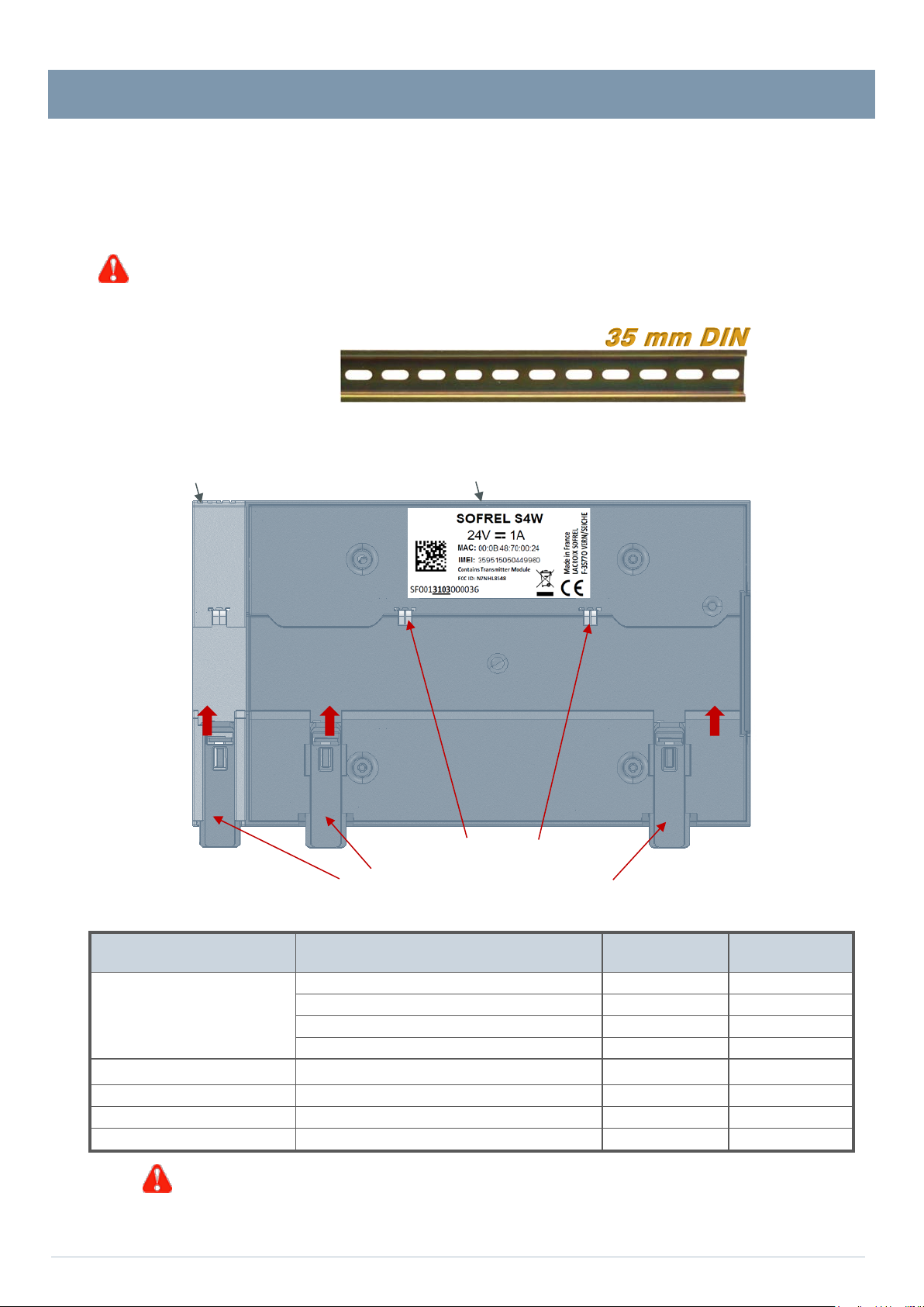
Case - Mounting
tipping (this note also applies to each I/O expansion module).
Rear view of the case
For the battery, use Faston crimp lugs 6.35 mm female type insulated re d .
Case - Mounting
The SCADA Central Station must be installed b y qualified personnel in accordance with local regulations (NF C 15-100 in France,
NEC in the U.S., etc.)
The case must be installed in a fire-resistant enclosure. This enclosure must stay closed during normal operation; it is only accessible
by qualified personnel and requires a key or tool to open it. The case is mounted on a standard metal DIN rail (35 mm).
The DIN rail is required to be connected to Ground; the grounding connection is carried out automatically when
the case is mounted.
To remove the case from the DIN rail, the user will use a screwdriver-type tool.
If the fasteners become unfastened, the user must make sure to replace th em to prevent the case from
I/O expansion modules and Compact case
35 mm DIN
Automatic ground terminals
Automatic locking on DIN rail
Cable sections
Access Cable
single-core cable 0.14 / 26 1.5 / 16
Inputs / Outputs
Power and Battery
With multi-strand cable: use crimping ferr ule s type DIN 46228 T4 or DIN 46228 T1.
stranded cable without tip 0.14 / 26 1.5 / 16
multi-strand with insulated tip DIN 46228 T4 0.14 / 26 1.0 / 17
multi-strand with non-insulated end DIN 46228 T1 0.14 / 26 1.5 / 16
monofilament 0.75 / 18 1.5 / 16
multi-strand without tip 0.75 / 18 1.5 / 16
multi-strand with mouthpiece DIN 46228 T4 0.75 / 18 1.0 / 17
multi-strand with non-insulated end DIN 46228 T1 0.75 / 18 1.5 / 16
Min. section
mm² / AWG
Max. section
mm² / AWG
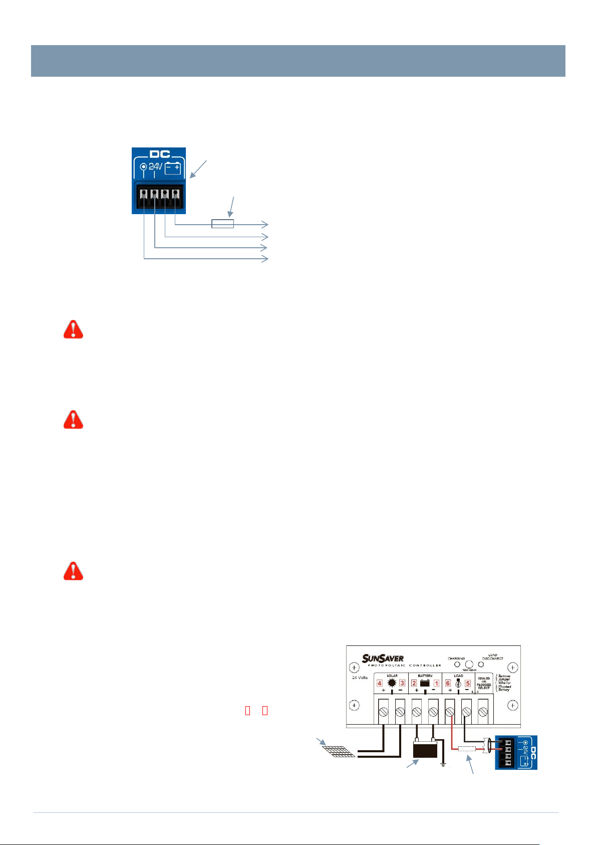
Case – Power supply
Power connector
∅
•
•
•
•
•
•
Switch the case and the I/O modules off before removing or adding COM modules.
Switch the case off befor e remov ing or add ing I/O modules.
the battery to prevent deep discharge and premature wear.
or 2 X 12 V batteries (in series)
3A fuse
Case – Power supply
The Compact case provides power for itself, as well for the COM modules (including the RDRTU-2 mod em connect ed to the R S485
(∗)
module)
power supply must be TBTS/ES1.
. The entire unit is compatible with a 24 VDC (± 20%) s upply voltage and is protected against reverse polarity. The 24 VDC
For the power supply, use a 0,75 mm² cross-sectional
5A fuse: Installation of a fuse is recommended on the Battery input.
+ or Battery Input
– or Battery Ground
+24 VDC
0V or GND
minimum.
If there is no 24 V
According to the RTU hardware configuration, 2 references are available (refer to the power balance table):
DC source in the electrical control panel, it is necessary to use a "24 VDC" converter box
40 W (60°C MAX)
90 W (70°C MAX)
The device's isolating mechanism is the ‘24 VDC + backup battery’ power connector.
Powering the I/O modules
The I/O modules have a separate 24 Vdc power supply, independent of the compact case: it is not backed up by the battery.
Simply connect a single I/O module to a 24 V
propagates to other installed modules.
The device's isolating mechanism is the ‘24 VDC’ power connector.
DC power source (according to the power balance); this power source automatically
Backup battery
The power supply to the case can be backed up with a 12 VDC lead battery, either 4 Ah or 12 Ah.
A periodic battery capacity test is performed automatically. The RTU manages the charge and performs continuous self-testing
of the external battery:
• Prot ection against overloads
• Automatic shut-off in the event of a short-circuit
• Prot ection against reverse polarity.
• Battery detection.
• Pr otection against deep discharges (threshold at 10.2 V).
When powering via backup battery, the voltage must be at least 12 V ±200 mV to start up;
When the product has started, its operating range is between 10.2 V and 13.8 V. Furthermore, when the RTU
power supply is voluntarily cut off for a long period (typically 48 hours or more), it is necessary to disconnect
Powering via solar panels
24V solar panel controllers are connected directly to the GND and +24 V
Use of SunSaver controllers is recommended: contact our t echnical
sales departmen t to ensure se lection of t he appropri ate controller
type (6, 10 or 20) and sizing of the solar panel according to the
geographic location of installation. Make sure to follow the
recommende d installation in dicated in the manua l provided with
the controller: assembly in vertical position, execution of the
connections in asc ending order of the terminal strips 1 to 6 on th e
diagram opposite (ba ttery, solar panel, then the RTU last), position of
the jumper for the use of an open battery, etc.
(∗)
:
Only available in countries where 869MHz frequency is allowed, check with country’s regulations.
DC
24 V panel
terminals.
A 24 V battery
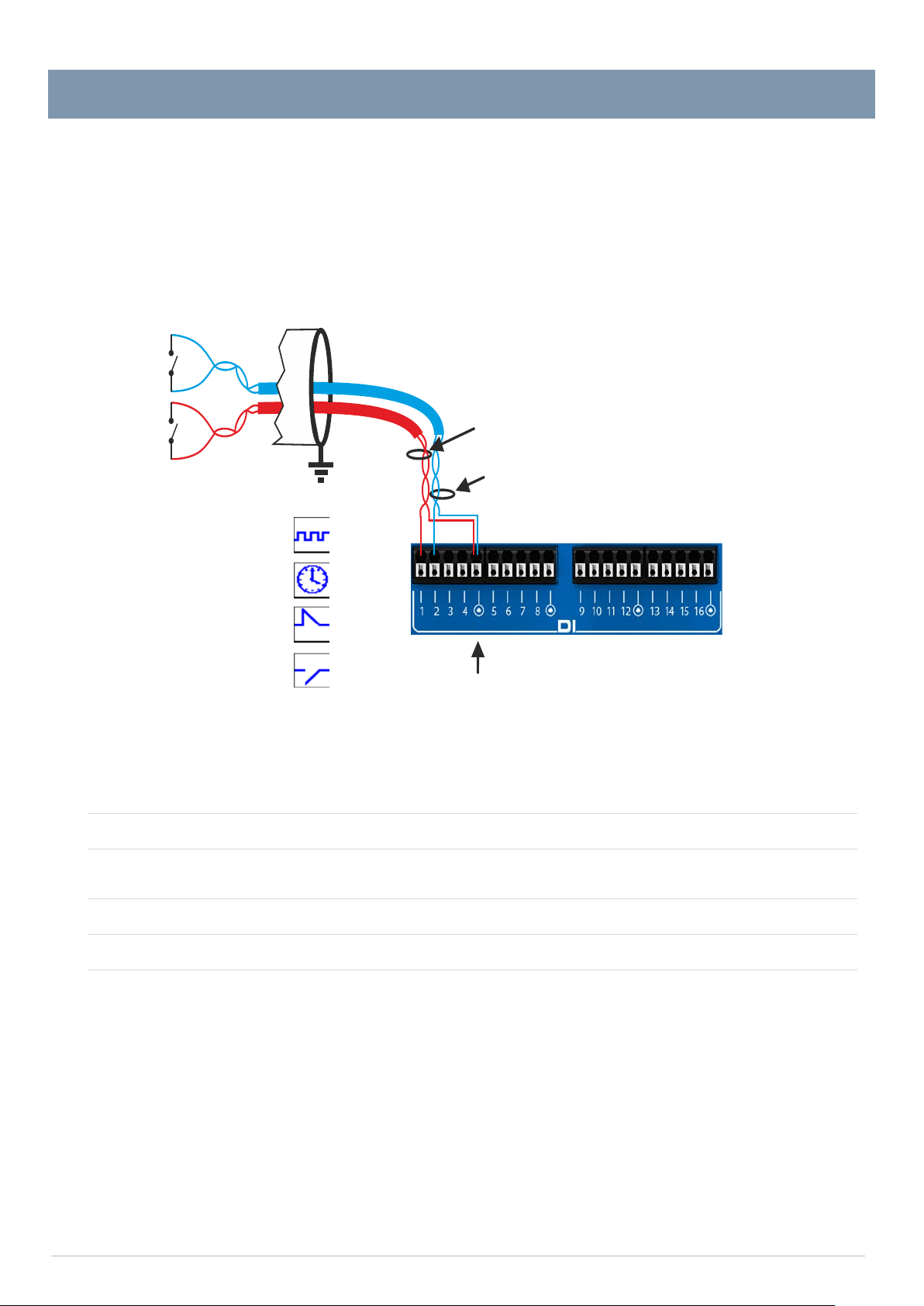
Case - Inputs/Outputs
1 pair
for digital input no. 2
DI terminal strip:
Case - Inputs/Outputs
Connection of DIs
Example for 2 DIs:
Possible applications:
Pulse counters
Duration counters
Digital input loop: Normally closed
Digital input loop: Normally open
Cable for
digital inputs
for digital input no. 1
1 pair
1 shared for 4 digital inputs
Technical specifications
- Number of digital inputs: 16
- Contact type:
- Maximum length of cable:
- Digital input filtering:
- Isolation:
Dry self-powered contact: Normally open/ closed
(configurable positioning logic)
1,000 metres (AWG24 SYT+ cable type)
It is necessary to relay the digital inputs if the cable length is any higher
or if the cable crosses an environment with high interference.
Any steady state digital input can be used for the counter acquisition;
the minimum duration of the steady state is 2 ms (max frequency = 250 Hz)
The DIs are isolated from the rest of the electronics; the isolation voltage
is 3000 V
DC minimum. The DIs are not isolated from each other.
Case - Inputs/Outputs
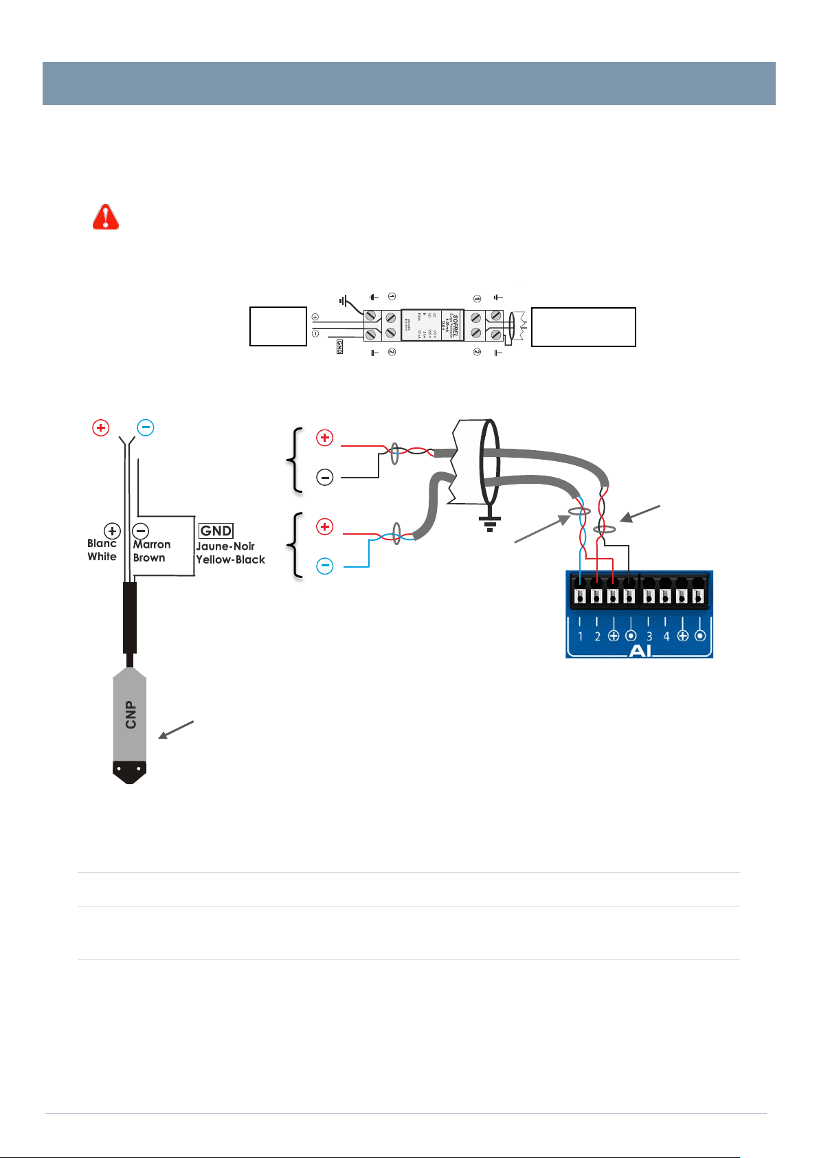
Sensor’ link cable runs
be installed on the RTU side.
AI terminal strip:
1 pair for ANA input no.1
1 pair for ANA input no. 2
1 pair
for ANA input no. 1
1 pair
for ANA input no. 2
Sensor, 4-20 mA
Connection of AIs (4-20mA)
Only sensors with floating output delivering a current source free from any reference with respect to Ground and, in all cases, several
sources having no common point between them, are directly compatible with our materials.
Otherwise, the installer must provide a galvanic isolation device in the ‘RTU – Sensor’ link.
Installation of surge arresters:
All SOFREL sensors come with inbuilt surge protection. Howe ver, if the ‘RTU –
outside of building or extends a significant length (> 200 metres), a 4-20 mA surge arrester should
Wiring a surge arrester
Example for 2 AIs, ‘4-20 mA’:
Sensor
(Case for auto n om o us s e ns or )
(Case for remotely powered sensor)
S4W
AI 4-20mA cable
Technical specifications
- Number of ANA inputs: 4 in measuring current 4-20 mA
- Type:
- Remote power feeding:
- Input impedance:
- Precision: 0.1% (25°C)
- Resolution: 16 bits
- 2 sensors per remote power feed
- Voltage = 16V
- Protection current = 50 mA (maximum for 1 or 2 inputs)
Ω
- 100
± 10 %
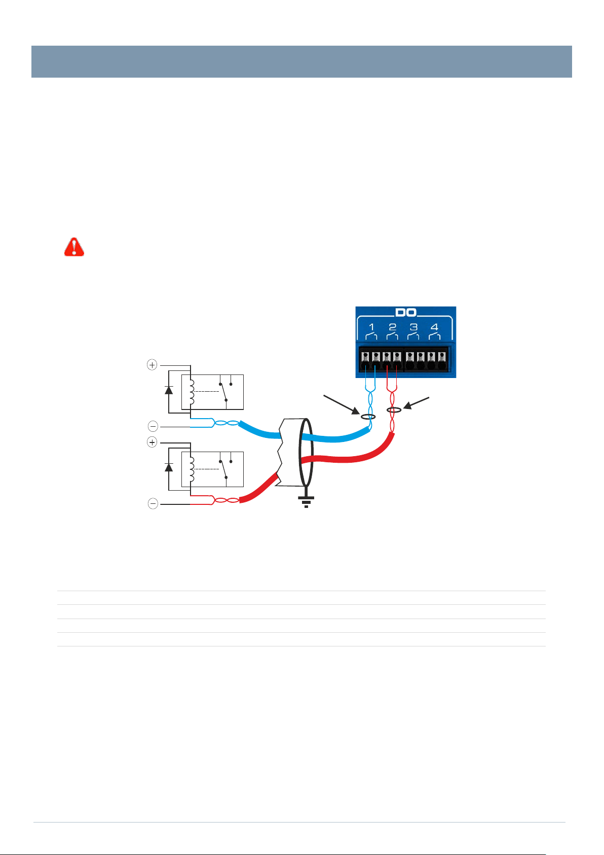
Case - Inputs/Outputs
The DO do not allow direct control of power units.
1 pair for the DO no.1
1 pair for the DO no.2
DC relay
DO terminal strip:
Connection of DOs
DOs are 12 V / 24 V AC/DC ’very low voltage’ voltage-relay type digital outputs: they are compatible with 24 V relays and control panel
indicator lights.
By default, and following a total power cut (24V and Battery), DOs are in their 'open' state (idle state = 0).
In case of product reinitialisation, the state of each DO is retained (no forced return to the idle state).
The user defines the ‘bistable’ or ‘impulse’ control type when configuring each DO data point.
When a DO is configured to control the ‘Watchdog safe ty’ feature; this output is reinitialised according to inverse logic (the output is
in the closed state if no default; it switches to t he open state if a default is pres ent). This 'Watchdog' output is very usef ul for controlling
power supply and for the proper functioning of the RTU (see § ‘Data processing – Operational safety’).
Example of control of 2 DC relays by 2 DO:
DC relay
Technical specifications
- Number of DO: - 4 in alternating current (AC) and/or direct current (DC)
- Output type:
- Maximum switching voltage:
- Continuous current:
- Isolation:
- free from all potential
- 24 V AC/DC +20% (40 V peak)
- 150 mA
- 1500 V
between the DO and the control case
RMS
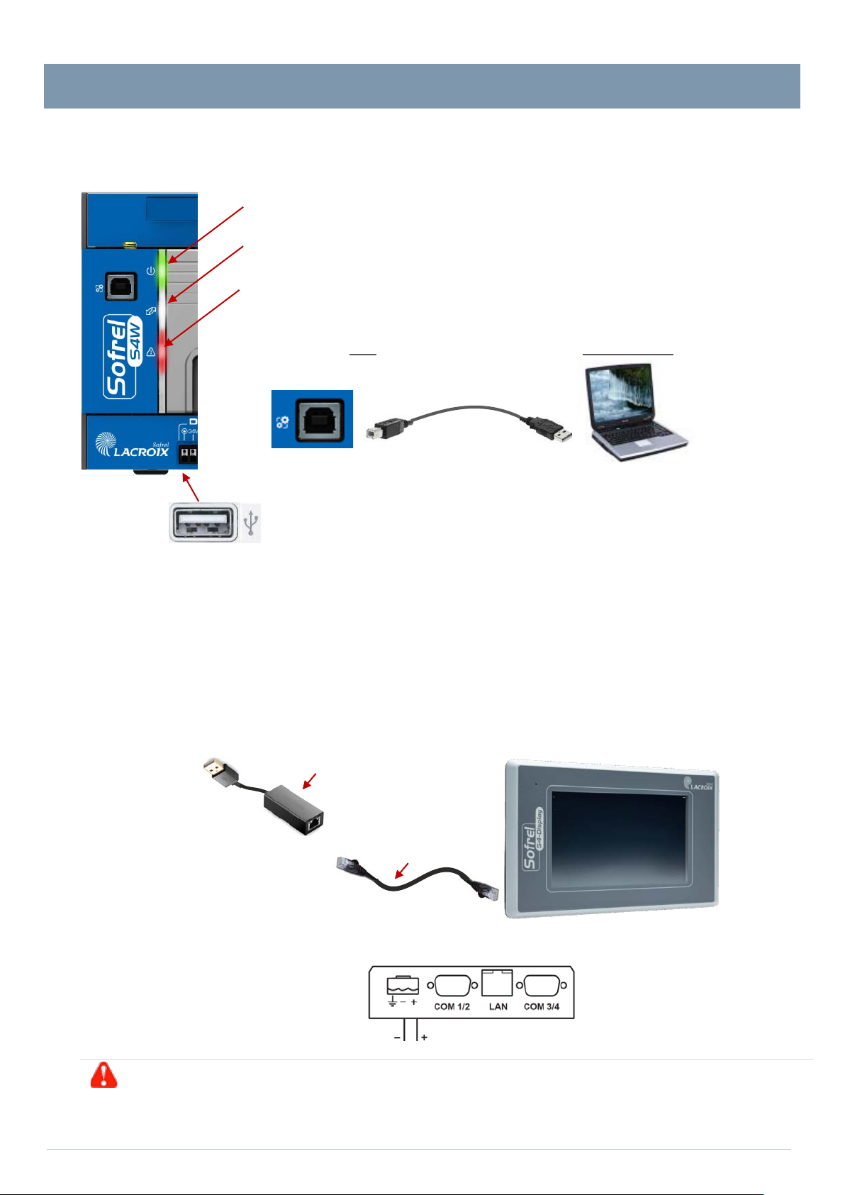
Case – Indicator lights and USB ports
RED
On the front
UNDER THE CASE, the second USB port connects to the S4 Display.
•
Maximum thickness of the receiving panel = 5.5 mm
• Rear view:
Connection of 24V and LAN TERMINAL STRIPS
Black Red
Prepare a free space of 100 mm around the dis p l ay (above, below, behind), 50 mm on the sides.
Cable length = 2 metres
Ethernet USB adapter
2 m Ethernet cable
Case – Indicator lights and USB ports
3 indicator lights display the operating status of the RTU:
GREEN
WHITE
S4-Display connection
• Case power supply (light on if OK)
• Communication with the Centralised System (light on if connection OK)
• General system operation (light off if OK)
-face, the USB port, type B (printer), con n ects to the configuration PC.
The S4 Display must be flush mounted and facing forward in the control panel.
Dimensions:
• Front part = 170.4 × 106.8 × 7.5 mm
• Depth of the rear part = 41.7 mm
• Dimensions of the flush-mounting area = 160.7 x 93 mm
•
•
 Loading...