

Page 1
May 11 – V 3.1 A Functional description
1. Presentation
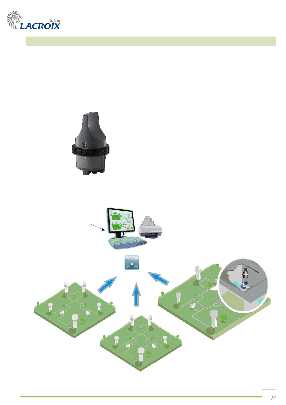
9 Typical application:
The Data Logger automatically collects the counting and flow values and measures
drinking water network pressure; it sends these data by SMS or GPRS once a day, to a
centralized system.
Powered by a Lithium battery, this product possesses a
power autonomy of several years.
Completely watertight, it conforms to the requirements
of the environment in which it is placed: in particular
when fitted underground, or in a wet or flood-prone
counting manhole.
9 Network mimic diagram:
SCADA Central Station
SMS communications or GPRS
via GSM network
1
Page 2

2. User interfaces
2
3
SOFTOOLS:
configuration, diagnostics
9 Configuration read / w r ite,
9 Diagnostics.
1 4
Key:
local wake-up on key
SCADA Central Stations:
SMS or GPRS communication
9 Network data centralization.
Mobile phone:
SMS communication
9 Local wake-up for indexing,
communication diagnostics, etc.
Legend:
Bluetooth communication
SMS communication
GPRS communication
9 Sending command SMSs from
the user's mobile phone
request, meter indexing, etc.),
9 Receipt of warning messages
on the user's mobile phone.
(data status read
2
Page 3
3. Hardware properties
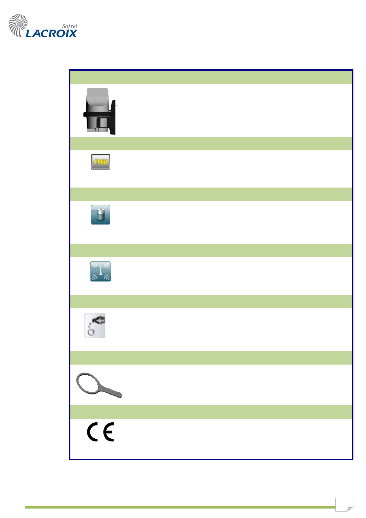
Case
Watertightness
Autonomy
Aerial
Dimensions in mm: H = 261 x W = 155 x D = 176
(the case can be wall-mounted using 2 screws)
Input cable connector: watertight bayonet connector (military grade)
With its IP68 protection rating, the Data Logger can be fitted in a wet or flood-prone manhole.
The case is protected against the effects of prolonged submersion, up to 100 days in 1 meter
of water.
The "934" battery (or standard battery) is optimized to provide the Data Logger with an
operating autonomy of several years.
The "933" battery (or high capacity battery) can be used to significantly increase the Data
Logger's autonomy.
Key
Tool
Electrical safety
The built-in GSM aerial has been specifically designed to improve communication quality over
GSM networks in difficult environments (particularly in buried manholes).
An optional external aerial can be connected to the case.
The key enables a user to wake the Data Logger to write the configuration and to run operating
diagnostics (communication tests, meter indexing, GSM reception level check, etc.).
These operating tests can be performed either using the indicator lights, using either
SOFTOOLS in Bluetooth communication mode, or with a mobile phone via SMS.
This specific tool is required to correctly open and close the case; it matches the locking system
and maintains the product's seal.
EN 60950 standard:
In accordance with current European regulations, this device is intended for use in an industrial
environment. It presents no hazardous voltage, in accordance with the low voltage directive (for
further details, see § "Environmental standards and conditions").
3
Page 4

4. Functional characteristics
Configuration
Configuration read/write via SOFTOOLS via Bluetooth and SMS communication.
Diagnostics
Operating checks and communication tests:
- using the indicator lights,
- using SOFTOOLS in Bluetooth communication mode,
- using a mobile phone in SMS communication mode.
Data acquisition
4 DIs can be configured to manage meters and signaling.
Characteristics of meter inputs:
- minimum pulse duration: 2 ms (max. frequency: 250 Hz).
- for meters with an open collector transistor type output (capacity < 220 pF).
2 These characteristics apply to products bearing a serial number greater than or equal to 04xxxxxxxx;
for earlier versions, the maximum pulse duration is 20 ms (max. frequency: 25 Hz).
2 optional AIs for acquiring two "4-20 mA" measurements converted to 10 bits for remotely powered
sensors.
Data calculations
Periodical data calculation:
- for daily reports (volumes),
- average flows (values expressed in m /h),
- nighttime flow to monitor flow over a user-definable time period.
- for thres on AI measurements and/or average meter flow rates. holds
Archiving
Large storage capacity: up to 50,000 values archived.
3
Periodical archiving of meter indices, average flows and AI measurement s (e.g.: every 15 mn).
Daily report archiving (current index, daily volume, min., max. and night flow).
Communication with SCADA Central Stations
The Data Logger communicates with a centralization system whose type can be configured:
SCADA central stations via SMS or GPRS, or with a WEB server via GPRS.
• By SMS: the Data Logger sends archived SMS messages to 1 or 2 SCADA Central Stations. On
a change of state, the Data Logger can instantly send an SMS messag e of current states and all
the archived SMS messages to the SCADA Central Stations.
• By GPRS: the unit initiates communications with the central system; it can be us ed on a GPRS
network with a private (or dedicated) APN or a public (standard) one.
On each GPRS communication, the Data Logger sends the central system the archived values
of its data, the daily reports and diagnostic data.
By default, the unit communicates once daily with the centralization system, though in certain cases, for
specific needs, multiple daily transmissions can be programmed (based on configurable times, or
periodically).
Communication with a mobile phone
The Data Logger can send warning messages to the user's mobile phone.
The user can issue Diagnostic commands via SMS messages.
4
Page 5

∅
July 2010 – V 2.2 A Unit's Installationa
1. Watertightness
This unit has an IP68 protection rating; it is fully protected against the effects of immersion
and can be fitted in a manhole in a wet or flood-prone environment. The product's "IP68
watertightness" guarantee implies that the SIM card must be inserted into the case by the
supplier at the time of delivery.
2. Case characteristics
nsions 2.1. Dime
176 155
2 screws
∅ 4
2.2. Mounting bracket
following characteristics:
8
∅
30 mm
148 261
ecurely mounted with 2 screws and 2 plugs (not supplied) with the The bracket must be s
4
148
1
Page 6

3. Precautions for use
Tool
Case locking
clip
3.1. Opening the case
The ca
open
ed exce
To open the
Proceed similarly to close the case; use the tool to tighten the ring until the clip locks
Do not tighten beyond the clip.
n be kept watertight by screwing the case ring tightly. The case must not be
se ca
pt for insertin
case, we recommend:
locking the case in the "upside down" position, either between your knees, or in a
•
vise (though care must be taken to avoid damaging the plastic)
inserting the tool into the notches provided for this purpose and rotating it
•
clockwise
3.2. Battery power
The Lithium battery may be potentially hazardous; the following recommendations
for use must therefore be followed:
• Do not recharge, short-circuit, cru sh or dismantle; do not heat beyond 100°C
or incinerate.
• Risk of fire, explosion and burns.
g the SIM card or replacing the battery.
(in this position, the tightening and loosening directions are reversed).
.
2 To protect the environment, return spent batteries to your supplier for recycling.
When transporting, please conform to the UN standards described in the "Standards
and conditions of use" document for category UN 3091 - Class 9 instruments.
3.3. Optimizing the case position
To improve GSM communications, the unit's position in the manhole must be carefully
considered; it should generally be kept away from the manhole cover. Mount the case
vertically on its bracket, in accordance with the case's Top and Bottom.
The tests should be conducted in a real situation, with the manhole cover closed.
1) The indicator lights on the Remote Terminal Unit provide an initial diagnostic level.
2) SOFTOOLS, in Diagnostics mode, can be used to search for the best operator.
3) The user must find the best position for the case in the manhole using the
"Reception level test" function, via SOFTOOLS in Diagnostics mode, or using a
mobile phone to send a command no. 7 SMS (see § “Configuration and
Diagnostics”).
2
Page 7

A
A
4. Connecting DI / AI inputs
The DI / AI inputs cable can be disconnected from the case to facilitate the connection of
the various devices.
DI 1
to
DI 4
AI 1
and
AI 2
• "Standard" meter:
DI 1: counting pulses (LF signal)
or
• "In / out" meter:
DI 1: counting pulses (HF signal)
DI 2: w flow direction outward = 0
ater
inward = 1
or
• Logical datum (signaling)
• 4-20 mA measu
(sensor powered by the Unit)
or
• 4-20 mA mea rement (autonomous sensor) su
rement
DI 1
DI 2
DI 3
DI 4
AI 1
AI 2
White / Blanc
Brown / Marron or Black / Noir
Green / Vert
Brown / Marron or Black / Noir
Yellow / Jaune
Brown / Marron or Black / Noir
Red / Rouge
Brown / Marron or Black / Noir
Purple / Violet
Pink / Rose
Blue / Bleu
Grey / Gris
I 1
I 2
Brown / Marron or Black / Noir
Pink / Rose
Brown / Marron or Black / Noir
Grey / Gris
NC
NC
Purple / Violet
Blue / Bleu
2
All inputs are protected up to a maximum voltage of 12 volts.
3
Page 8

1
General precautions
Electrical safety : Directive 73/23/EEC modified 93/68/EEC “Low Voltage”
Electromagnetic compatibility: Directive 89/336/EEC “Electromagnetic compatibility”
Standard
Access
Type
Reference
Level
EN 55022:
Electromagnetic field
EN 61000-4-3
10 V/m
Transient bursts
EN 61000-4-4
Shock waves
EN 61000-4-5
Conducted disturban c es
EN 61000-4-6
10 V
Telecommunications: Directive 1999/5/EC "Telecommun icati on Ter min als "
Federal Communications Commission (FCC)
Temperature
Use -20°C to +55°C
Storage
-25°C to + 70°C
Humidity
EN 60529 (June 2000)
Usage and Storage
IP68
100 days in 1 meter of water
Environmental protection
Fev. 12 – V 3.1 D Standards and conditions of use
UN Recommendations:
EN 60950: Data processing
hardware safety
Data processing instrument
(class B) emissions
EN 55024:
Industrial environment
immunity
ETSI EN 301 511 GSM 900 and DCS1800 access
FCC Recommendations:
This product is powered by a lithium battery; only those batteries specified by the product manufacturer are suitable to
guarantee its safety and performance. The use of batteri es of an y other type is at the user's own risk.
The presence of a lithium battery positions this device in “categor y UN3 09 1 – Class 9” of the UN list of hazardous materials. As
such, the transport of this device must conform to prevailing rules that are specific to the means of transport used, both in terms
of packaging, identification and accompanying documents. In all cases, the carrier must be informed of the specific contents of
the package.
The warning label opposite (Hazard label for Class 9 - Miscellaneous Hazardous Goods) must be affixed onto the
packaging and remain visible on the outside of the package. This type of label is available from ca rri ers o r fr om
packaging suppliers.
Electric shock, Energ y trans f er ha zar d, Fire, Mechanical and thermal ha zar ds .
Case Radiation disturbances
Case
Inputsoutputs
This device complies with Part 15 of the FCC Rules. Operation is subject to the following two conditions: (1) this device may not
cause harmful interference, and (2) this device must accept any interference received, including interference that may cause
undesired operatio n.
This equipment has been test ed and found to comply with the li mits for a Clas s B digital device, pursuant to part 15 of the FCC
Rules.
These limits are designed to provide reasonable protection against harmful interference in a residential installation. This
equipment generates uses and can radiate radio frequency energy and, if not installed and used in accordance with the
instructions, may cause harmful interference to radio communications.
However, there is no guarantee that interference will not occur in a particular installation. If this equipment does cause harmful
interference to radio reception, which can be determined by turning the equipment off and on, the user is encouraged to try to
correct the interferenc e by one or more of the follo wi ng measures:
- Increase the separation between the equipment and receiver.
- Consult the dealer
This portable equipme nt wit h its an tenna complies with FCC ’s radi ati on exposure limits set forth for an uncontrolled environment.
To maintain compliance, follow the instructions below :
Changes or modifications not expressly approved by the party responsible for compliance could void the user's authority to
operate the equipment.
Electrostatic discharges EN 61000-4-2
1. This transmitter must not be c o-located or operating in conjunction with any other antenna or transmitter.
2. Avoid direct contact to the an ten na , or kee p co nta ct to a mi ni mu m while us in g thi s equi pment.
4 kV by cont act
8 kV through air
Level 4
WEEE directives
For reasons of environmental protection, spent products should be returned to their respective suppliers for waste recycling.
2002/96/EC
and 2003/108/EC
Collection and sorting of Waste Electrical
and Electronic Equipment (WEEE),
processing, recycling and non-polluting
disposal
 Loading...