

L-Acoustics V-DOSC Operator's Manual

Version 4
June 2005
V-DOSC
OPERATOR MANUAL

L-ACOUSTICS V-DOSC Manual Version 4 6/29/2005 Page 2 of 158

FOREWORD
This manual is intended for Qualified V-DOSC Technicians and Certified V-DOSC Engineers who are
responsible for the installation and operation of the V-DOSC
sound reinforcement system. It is also
intended to provide interested sound engineers, designers, consultants and installers with information
regarding the fundamental principles of Wavefront Sculpture Technology and how these principles
are embodied within V-DOSC. Specifications, installation procedures and general guidelines for sound
design and system operation are also discussed in this document.
MANUAL ORGANIZATION
The Introduction gives a brief presentation of V-DOSC and explains why specialized training is
necessary to work with the system
Chapter 1 presents the fundamentals of Wavefront Sculpture Technology and introduces the
elements of the V-DOSC system standard
Chapter 2 describes V-DOSC array performance and coverage prediction
Chapter 3 discusses sound design issues
Chapter 4 gives detailed procedures for rigging and stacking V-DOSC
Chapter 5 describes system operation including preset selection, tuning and operation
Chapter 6 lists recommended installation and maintenance tools
Chapter 7 provides V-DOSC system specifications
Appendices elaborate on a number of technical aspects and provide additional theoretical details
L-ACOUSTICS V-DOSC Manual Version 4 6/29/2005 Page 3 of 158
AUTHOR’S NOTE:
Paradigm shifts don’t occur very often in the sound reinforcement industry∗ – especially when a small,
relatively-unknown (at the time!) French loudspeaker company is responsible for them.
Today’s V-DOSC is very different from the V-DOSC of 1992. Constant improvements have been
made to the loudspeaker itself and its components – providing improved performance and durability
while maintaining full backwards compatibility. The latest Version 7 preset release provides smoother
mid/high response, optimized low end and sub/low processing with a simplified subwoofer time
alignment procedure. Better overall utilization of system power resources is the result along with
increased SPL output. With the V7 release, many have perceived V-DOSC as a new loudspeaker and
with the new sub/low modifications, as a new system.
To complement the V7 preset release, the number of supported DSP platforms was also increased to
benefit from recent advances in DSP technology. SOUNDVISION modeling software has allowed for
more accurate performance prediction than ever and the introduction of new system accessories has
provided added flexibility. As for the rigging system, this in itself was a radical innovation in its day and
even now provides speed and flexibility that captive rigging systems can’t equal.
That’s what new – what’s old is that V-DOSC remains the reference that other line arrays are
compared to and has become a modern day classic. But V-DOSC is not just a speaker, it is a standard
system and through the V-DOSC Network, a worldwide service - including highly-trained technicians
(over 1,500 people have been through V-DOSC and dV-DOSC training as of this writing). V-DOSC is
a mature, proven system that will continue to benefit from ongoing evolution and improvements with
a strong emphasis on technical support through training, modeling, project support and R&D.
In closing, it has been an honor and a pleasure to work with V-DOSC over the years and a few thank
you’s are in order:
®
Dr. Christian Heil, Professer Marcel Urban, Joel Perret, Herve Le Gall, the L-ACOUSTICS
R&D
team (Christophe Pignon, Christophe Combet, Jacques Spillman) and the L-ACOUSTICS Technical
Support team (Bernie Broderick, Cedric Montresor and Dave Brooks).
All V-DOSC Network Partners, V-DOSC Trainers, CVEs and QVTs around the world. You’re too
numerous to thank individually but my sincere thanks for your hard work and support over the years.
Paul D. Bauman
June 2005
Hmm…. What’s next? …..
∗
For those interested, “The Tipping Point” by Malcolm Gladwell is a book that describes how trends spread.
Makes for a good bus read…
L-ACOUSTICS V-DOSC Manual Version 4 6/29/2005 Page 4 of 158

TABLE OF CONTENTS
TABLE OF CONTENTS........................................................................................................................... 5
LIST OF FIGURES.................................................................................................................................... 8
LIST OF TABLES ....................................................................................................................................10
INTRODUCTION .................................................................................................................................. 11
WAVEFRONT SCULPTURE TECHNOLOGY FUNDAMENTALS ........................................................ 11
THE SOUND REINFORCEMENT PROBLEM .............................................................................. 11
WAVEFRONT SCULPTURE TECHNOLOGY BACKGROUND.................................................. 12
V-DOSC: THE SOLUTION ........................................................................................................... 14
V-DOSC TRAINING AND QUALIFICATIONS ..................................................................................... 18
QUALIFIED V-DOSC TECHNICIAN (QVT) .............................................................................. 18
CERTIFIED V-DOSC ENGINEER (CVE)..................................................................................... 18
1. THE V-DOSC SYSTEM STANDARD ............................................................................................... 19
1.1 V-DOSC SYSTEM COMPONENTS ............................................................................................... 23
LOUDSPEAKER ENCLOSURES ................................................................................................... 23
RIGGING ACCESSORIES.............................................................................................................. 24
SUBWOOFER ENCLOSURES....................................................................................................... 26
SUBWOOFER RIGGING ACCESSORIES..................................................................................... 26
AMPLIFICATION.......................................................................................................................... 27
AMPLIFIER RACKS ....................................................................................................................... 27
SIGNAL DISTRIBUTION AND CABLING................................................................................... 29
LOUDSPEAKER CABLING ........................................................................................................... 31
1.2 V-DOSC SPECIFICATIONS ........................................................................................................... 33
1.3 V-DOSC RIGGING SYSTEM.......................................................................................................... 34
1.4 SB218 SUBWOOFER SPECIFICATIONS....................................................................................... 35
1.5 SB218 RIGGING SYSTEM............................................................................................................. 37
1.6 POWERING V-DOSC .................................................................................................................... 38
1.7 V-DOSC AMP PANELS.................................................................................................................. 40
1.8 V-DOSC AMPLIFIER RACKs.......................................................................................................... 43
1.9 COMB CONNECTORS................................................................................................................. 45
1.10 CO24 CONTROL OUTPUT PANEL............................................................................................ 49
1.11 MD24 MULTI DISTRO PANEL................................................................................................... 50
1.12 CO6 CONTROL OUTPUT PANEL.............................................................................................. 50
1.13 APPROVED DIGITAL SIGNAL PROCESSORS............................................................................. 51
1.14 OEM FACTORY PRESETS........................................................................................................... 51
1.15 V-DOSC PRESETS....................................................................................................................... 52
LO/HI PRESETS ............................................................................................................................. 53
3-WAY STEREO PRESETS............................................................................................................53
3WX PRESET.............................................................................................................. 53
3W INFRA PRESET .................................................................................................... 53
4-WAY PRESETS ........................................................................................................................... 54
SUBWOOFER TIME ALIGNMENT RECOMMENDATIONS ................................. 54
L-ACOUSTICS V-DOSC Manual Version 4 6/29/2005 Page 5 of 158

SUB/LOW GAIN SCALING PROCEDURES ............................................................ 54
SUBWOOFER PRESETS (DELAY ARC, LCR) ......................................................... 54
INFRA PRESET........................................................................................................... 55
4W PRESET................................................................................................................. 55
X PRESET ................................................................................................................... 56
X AUX PRESET .......................................................................................................... 56
5-WAY PRESETS ........................................................................................................................... 57
5W INFRA PRESET .................................................................................................... 57
5W X PRESET............................................................................................................. 57
GENERAL GUIDELINES REGARDING SYSTEM PROTECTION ............................................... 58
XTA DP224 V-DOSC PRESETS ........................................................................................................... 59
XTA DP226 V-DOSC PRESETS ........................................................................................................... 60
LAKE CONTOUR V-DOSC PRESETS.................................................................................................. 61
BSS FDS 366 V-DOSC PRESETS ......................................................................................................... 62
2. V-DOSC COVERAGE MODELING ................................................................................................... 63
2.1 COVERAGE IN THE HORIZONTAL PLANE ................................................................................. 63
2.2 COVERAGE IN THE VERTICAL PLANE ........................................................................................ 64
Flat V-DOSC Array........................................................................................................................ 64
Curved V-DOSC Array.................................................................................................................. 64
Constant Curvature V-DOSC Array............................................................................................. 65
Variable Curvature V-DOSC Array .............................................................................................. 66
2.3 V-DOSC COVERAGE MODELING USING ARRAY 2004............................................................... 66
CUTVIEW SHEETS........................................................................................................................ 67
V-ARRAY1, V-ARRAY2 Input Data .............................................................................................. 67
Optimization Procedure................................................................................................................ 69
Output Data................................................................................................................................... 70
dV-ARRAY1, dV-ARRAY2 Input Data.......................................................................................... 72
dV-DOSC PICK POINT UTILITY ................................................................................................. 72
H-ISOCONT SHEET............................................................................................................................ 74
Input Data ...................................................................................................................................... 74
Optimization Procedure................................................................................................................ 74
Output Data................................................................................................................................... 74
2.4 V-DOSC COVERAGE MODELING USING SOUNDVISION ......................................................... 76
SOUNDVISION EXAMPLES ........................................................................................................ 80
SOUNDVISION STADIUM EXAMPLE ........................................................................................ 80
SOUNDVISION ARENA EXAMPLE............................................................................................. 82
3. SOUND DESIGN ............................................................................................................................... 85
3.1 STACKED OR FLOWN? ................................................................................................................ 85
Stacking Guidelines ....................................................................................................................... 86
Flying Guidelines ............................................................................................................................ 87
3.2 ACHIEVING OPTIMUM COVERAGE............................................................................................ 88
3.2.1 THE LEFT/RIGHT CONFIGURATION........................................................................................ 88
Tradeoffs Between Intelligibility and Stereo Imaging ................................................................. 88
3.2.2 LEFT/CENTRE/RIGHT (LCR) CONFIGURATIONs..................................................................... 89
3.3 MULTIPLE ARRAY CONCEPTS .................................................................................................... 90
3.4 SUBWOOFERS.............................................................................................................................. 92
3.4.1 Flown V-DOSC and Ground Stacked Subwoofers.............................................................. 93
3.4.2 Physically Coupled Subwoofers............................................................................................ 95
3.4.3 Hybrid Flown/Stacked Subwoofers ..................................................................................... 96
L-ACOUSTICS V-DOSC Manual Version 4 6/29/2005 Page 6 of 158

3.5 SUBWOOFER ARRAYING TECHNIQUES..................................................................................... 97
3.5.1 LEFT/RIGHT CONFIGURATIONS ...................................................................................... 97
3.5.2 CENTRAL LINE ARRAY WITH ELECTRONIC DELAY PROCESSING............................. 99
3.5.3 LEFT/CENTRE/RIGHT CONFIGURATIONS .................................................................... 100
3.5.4 LARGE FORMAT SUBWOOFER ARRAY CONFIGURATIONS ...................................... 102
3.6 COMPLEMENTARY FILL SYSTEMS ........................................................................................... 105
3.6.1 FRONT FILL........................................................................................................................ 105
3.6.2 OFFSTAGE FILL...................................................................................................................106
3.6.3 DELAY SYSTEMS............................................................................................................... 107
4. INSTALLATION PROCEDURES .................................................................................................... 109
4.1 STACKED SYSTEM ..................................................................................................................... 109
4.2 FLOWN SYSTEM ........................................................................................................................ 112
5. V-DOSC SYSTEM OPERATION..................................................................................................... 123
5.1 SYSTEM TONAL BALANCE ........................................................................................................ 123
5.2 MEASUREMENT PROCEDURES ............................................................................................... 125
Measurement Instruments.......................................................................................................... 125
Measurement Tips ....................................................................................................................... 126
Step-By-Step Tuning Procedure................................................................................................. 127
6. MAINTENANCE AND INSTALLATION TOOLS .......................................................................... 129
6.1 Recommended Maintenance Procedures ................................................................................... 129
6.2 Recommended Maintenance Tools............................................................................................. 129
6.3 Spare Parts ................................................................................................................................. 130
6.4 Recommended Installation Tools ................................................................................................ 131
7. SPECIFICATIONS ........................................................................................................................... 132
7.1 V-DOSC ENCLOSURE SPECIFICATIONS................................................................................... 132
7.2 SB218 SUBWOOFER SPECIFICATIONS..................................................................................... 134
7.3 RIGGING STRUCTURES ............................................................................................................ 135
V-DOSC BUMP2 Bumper ........................................................................................................... 135
SB218 BUMPSUB Rigging Bar ................................................................................................... 136
7.4 CO24, MD24 Line Assignment Summary.................................................................................... 137
7.5 CO24 Control Output Panel Line Assignments ........................................................................... 138
7.6 MD24 Multi Distro Panel Line Assignments................................................................................ 140
APPENDIX 1: Why Do Separated Sound Sources Interfere?.......................................................... 142
APPENDIX 2: Further Explanations Regarding WST Criteria ........................................................ 142
APPENDIX 3: How Does V-DOSC Behave With Respect To WST Criteria................................... 148
APPENDIX 4: How Does the DOSC Waveguide Work? .................................................................. 149
APPENDIX 5: The Border Between Fresnel And Fraunhofer Regions........................................... 150
APPENDIX 6: Pattern Control of a Constant Curvature Array ...................................................... 152
APPENDIX 7: WST Criteria Number 5 ............................................................................................. 153
APPENDIX 8: Angle Strap Calibration .............................................................................................. 154
APPENDIX 9: V-DOSC Rigging Certification .................................................................................... 155
L-ACOUSTICS V-DOSC Manual Version 4 6/29/2005 Page 7 of 158

LIST OF FIGURES
Figure 1: Wavefront interference versus a sculptured V-DOSC wavefront.................................................... 12
Figure 2: Wavefront Sculpture Technology Conditions 1 and 2 Illustrated.................................................... 13
Figure 3: Coplanar Symmetry of V-DOSC ..................................................................................................... 15
Figure 4: Cylindrical versus spherical wave propagation................................................................................ 16
Figure 5: V-DOSC Array ................................................................................................................................17
Figure 6: V-DOSC System Block Diagram .....................................................................................................20
Figure 7: LR System Configuration ................................................................................................................. 21
Figure 8: LR System Plus Offstage Fill Configuration..................................................................................... 22
Figure 9: V-DOSC system loudspeakers plus accessories.............................................................................. 23
Figure 10: V-DOSC Rigging Accessories ......................................................................................................... 25
Figure 11: V-DOSC Subwoofer Options.........................................................................................................26
Figure 12: Subwoofer Rigging Accessories ...................................................................................................... 26
Figure 13: L-ACOUSTICS LA48a Power Amplifier......................................................................................... 27
Figure 14: Amplifier Rack Options and Accessories........................................................................................28
Figure 15: Signal distribution and cabling......................................................................................................... 30
Figure 16: Loudspeaker cabling options .......................................................................................................... 32
Figure 17: V-DOSC Enclosure - Front and Rear Views...................................................................................33
Figure 18: V-DOSC BUMP2............................................................................................................................34
Figure 19: BUMPDELTA ................................................................................................................................. 35
Figure 20: SB218 Subwoofer – Front and Rear Views ....................................................................................36
Figure 21: BUMPSUB SB218 Flying Bar ..........................................................................................................37
Figure 22: V-DOSC PADO4a Amplifier Rack Panel........................................................................................ 40
Figure 23: V-DOSC PADO2a Amplifier Rack Panel........................................................................................ 40
Figure 24: PADO4a amp rack wiring...............................................................................................................41
Figure 25: PADO2a amp rack wiring...............................................................................................................42
Figure 26: L-ACOUSTICS Amplifier Rack RK124a loaded with 4 x L-ACOUSTICS LA48a amplifiers........... 43
Figure 27: L-ACOUSTICS Amplifier Rack Options......................................................................................... 44
Figure 28: L-ACOUSTICS RK122a amplifier rack channel assignments and cabling....................................... 46
Figure 29: L-ACOUSTICS RK124a amplifier rack channel assignments and cabling....................................... 46
Figure 30: L-ACOUSTICS RK122a amp rack channel assignments for 2-way, 3-way stereo presets ............47
Figure 31: L-ACOUSTICS RK124a amp rack channel assignments for 2-way, 3-way stereo presets ............48
Figure 32: CO24 Control Output Panel..........................................................................................................49
Figure 33: MD24 Multi Distro Panel................................................................................................................ 50
Figure 34: CO6 Control Output Panel............................................................................................................50
Figure 35: Spectral balance for SUB/LOW versus MID/HI Sections ...............................................................53
Figure 36: Spectral balance for SUB/LOW versus MID/HI Sections (V6 presets and earlier)......................... 53
Figure 37: Infra preset time alignment procedure........................................................................................... 55
Figure 38: 4W preset time alignment procedure ............................................................................................55
Figure 39: X preset time alignment procedure ............................................................................................... 56
Figure 40: X AUX preset time alignment procedure...................................................................................... 56
Figure 41: 5W Infra preset time alignment procedure ....................................................................................57
Figure 42: 5W X preset time alignment procedure ........................................................................................57
Figure 43a: Horizontal V-DOSC isocontour averaged from 630 Hz - 16 kHz ...............................................63
Figure 43b: Horizontal V-DOSC isocontour averaged from 32 Hz - 630 Hz .................................................63
Figure 44: Constant Curvature Array Examples. ............................................................................................65
Figure 45: Defining Cutview Dimensions ........................................................................................................ 67
Figure 46: Parameters for the ROOM DIM Utility Sheet in ARRAY ............................................................... 68
Figure 47 (a): Cutview showing non-constant enclosure site angle impact spacing........................................ 69
Figure 47 (b): Cutview showing constant enclosure site angle impact spacing............................................... 69
Figure 47 (c): Plan view representation of non-constant (a) versus constant spacing (b) arrays ....................69
Figure 48: ARRAY 2004 Geometric Data for V-DOSC................................................................................... 71
Figure 49: ARRAY 2004 Geometric Data for dV-DOSC.................................................................................73
Figure 50: ARRAY 2004 spreadsheet calculation example .............................................................................. 75
L-ACOUSTICS V-DOSC Manual Version 4 6/29/2005 Page 8 of 158

Figure 51: SOUNDVISION Geometric Data for V-DOSC ............................................................................. 77
Figure 52: Plan view SPL mappings at octave band frequencies for 12 V-DOSC ...........................................78
Figure 53: Impact coverage and SPL mappings for 12 V-DOSC .....................................................................79
Figure 54a: Stadium example - rear perspective view of full system impact coverage ................................... 80
Figure 54b: Stadium example - plan view of full system impact coverage ......................................................80
Figure 55: Stadium example - rear perspective view of 1-10 kHz SPL Mappings........................................... 81
Figure 56: Arena example -rigging plot ...........................................................................................................82
Figure 57: Arena example - plan view of full system impact coverage............................................................82
Figure 58: Arena example - rear perspective view of full system impact coverage ........................................ 83
Figure 59a: Arena example - rear perspective view of full system SPL map (1-10 kHz) ................................83
Figure 59b: Arena example – plan view of 1-10 kHz SPL mappings ...............................................................84
Figure 60: Illustration of Stacking Guidelines................................................................................................... 86
Figure 61: Stacked system example................................................................................................................. 86
Figure 62: Illustration of flying guidelines......................................................................................................... 87
Figure 63: Flown V-DOSC System.................................................................................................................. 87
Figure 64: Tradeoffs between intelligibility versus stereo imaging.................................................................. 89
Figure 65: LCR Configurations ........................................................................................................................89
Figure 66: Generic rigging plot for a V-DOSC system with main L/R FOH and LL/RR offstage fill arrays...... 90
Figure 67: Rigging plot for a L/R V-DOSC + flown SB218 system with LL/RR dV-DOSC offstage fill. .......... 91
Figure 68: Stereo dV-DOSC offstage fill system. ...........91
Figure 69: Flown V-DOSC and ground stacked subwoofer configurations ....................................................93
Figure 70: Flown V-DOSC and ground stacked subwoofer time alignment ................................................... 93
Figure 71: Time alignment location for flown V-DOSC, ground stacked L/R subwoofers .............................94
Figure 72: Physically coupled subwoofer configurations ................................................................................. 95
Figure 73: Hybrid flown/stacked subwoofer configurations............................................................................ 96
Figure 74: Hybrid flown/stacked subwoofer example ....................................................................................96
Figure 75: L/R Subwoofer arraying techniques................................................................................................98
Figure 76: Centre subwoofer line array (a) without and (b) with electronic delay processing....................... 99
Figure 77: Electronic delay processing examples using a 4- or 6-channel DSP............................................. 100
Figure 78: LCR Subwoofer arraying techniques ............................................................................................ 101
Figure 79: Large format subwoofer configuration with electronic delay processing ....................................102
Figure 80: Geometric coordinates for the SUB ARC utility spreadsheet in ARRAY2004 .............................103
Figure 81: Large format arena configuration – 4 delay taps ..........................................................................103
Figure 82: Large format open air festival configuration................................................................................. 104
Figure 83: Large format stadium configuration ............................................................................................104
Figure 84: Stereo infill and distributed front fill options ................................................................................ 105
Figure 85: Flown offstage fill system options.................................................................................................106
Figure 86: Stacked offstage fill system options .............................................................................................. 106
Figure 87: SOUNDVISION simulation for a LL/L/R/RR V-DOSC FOH system with 4 delay positions ........ 107
Figure 88: Flown and stacked delay systems................................................................................................. 108
Figure 89: Stacked dV-DOSC delay system .................................................................................................. 108
Figure 90: Flown V-DOSC delay system....................................................................................................... 108
Figure 91: Stacked V-DOSC offstage fill system............................................................................................ 111
Figure 92: SOUNDVISION mechanical data................................................................................................. 112
Figure 93: SOUNDVISION installation report data ...................................................................................... 113
Figure 94: ARRAY 2004 installation data .......................................................................................................113
Figure 95: Photo sequence showing the steps involved in flying V-DOSC ...................................................119
Figure 96: Recommended Installation Tools .................................................................................................131
Figure 97: V-DOSC Enclosure – Line Drawing .............................................................................................133
Figure 98: SB218 Subwoofer – Line Drawing................................................................................................134
Figure 99: V-DOSC Flying Bumper – Line Drawing...................................................................................... 135
Figure 100: SB218 Flying Bar – Line Drawing ...............................................................................................136
Figure 101: The Interference Problem.......................................................................................................... 142
Figure 102: Comb filtering due to path length differences between sources ...............................................143
Figure 103: Destructive interference ring for a line array at observation point M........................................ 144
L-ACOUSTICS V-DOSC Manual Version 4 6/29/2005 Page 9 of 158

Figure 104: The effect of varying frequency and listener position M on Fresnel rings.................................. 145
Figure 105: Destructive and constructive interference rings for a line array at observation point M........... 145
Figure 106: Constructive interference rings for a condensed point source line array. ................................. 146
Figure 107: Destructive interference rings out of beamwidth for condensed and standard line arrays ......147
Figure 108: Front view of V-DOSC array and vertically stacked DOSC waveguides ................................... 148
Figure 109: Horn Generated Wavefronts......................................................................................................149
Figure 110: DOSC Waveguide – Internal Section ........................................................................................149
Figure 111: Illustration of the Fresnel and Fraunhofer regions...................................................................... 150
Figure 112: Illustration of dborder and Dv for a flat 12 enclosure array....................................................... 151
Figure 113: Illustration of the variation of vertical coverage angle with frequency ......................................152
Figure 114: Angle strap calibration............................................................................................................... 154
LIST OF TABLES
Table 1: L-ACOUSTICS LA48a power amplifier ratings................................................................................. 38
Table 2: Load and Power Ratings for V-DOSC............................................................................................... 39
Table 3: PADO4a COMB Wiring Chart.......................................................................................................... 41
Table 4: PADO4a Internal Amp Rack Wiring Chart........................................................................................ 41
Table 5: PADO2a COMB Wiring Chart.......................................................................................................... 42
Table 6: PADO2a Internal Amp Rack Wiring Chart........................................................................................ 42
Table 7: V-DOSC preset DSP output channel assignment and COMB connector summary ......................... 45
Table 8: 2-way, 3-way stereo preset DSP output channel assignment and COMB connector summary....... 47
Table 9: SUB / LOW OPERATING BANDWIDTH SUMMARY ..................................................................... 52
Table 10: Recommended Limiter Threshold Settings ..................................................................................... 58
Table 11: XTA DP224 Presets ........................................................................................................................ 59
Table 12: XTA DP226 Presets ........................................................................................................................ 60
Table 13: Lake Contour Presets...................................................................................................................... 61
Table 14: BSS FDS 366 Presets .......................................................................................................................62
Table 15: Angle Strap Values ......................................................................................................................... 110
Table 16: Weights for flown V-DOSC system...............................................................................................136
Table 17: Whirlwind W6 MASS Connector Input/Output Line Assignments................................................ 137
Table 18a: CO24 W6 Pin Assignments..........................................................................................................138
Table 18b: CO24 W6 Socket Assignments ...................................................................................................139
Table 19a: MD24 W6 Pin Assignments .........................................................................................................140
Table 19b: MD24 W6 Socket Assignments ................................................................................................... 141
Table 20: Border (in m) Between Cylindrical (Fresnel) and Spherical (Fraunhofer) Zones.......................... 151
Table 21: Dv - Vertical Coverage Angle in the Farfield Region .....................................................................151
Table 22: WST Criteria Number 5................................................................................................................ 153
L-ACOUSTICS V-DOSC Manual Version 4 6/29/2005 Page 10 of 158

INTRODUCTION
The V-DOSC sound reinforcement system is different. We hope this manual will help you to
appreciate why and to understand the basic theoretical principles behind how V-DOSC works.
Understanding the concepts behind V-DOSC and Wavefront Sculpture Technology is just as
important as the many operational details related in this manual – the more you understand the big
picture, the more effectively you will use V-DOSC.
V-DOSC is a complete system approach – starting from the basic scientific question of how to
effectively couple sound sources then including aspects of performance prediction, sound design,
system installation, rigging, cabling, signal distribution, digital signal processing and system tuning. This
turnkey system approach allows for accurate and predictable results, however, in order to achieve the
best results you need to understand the theoretical concepts behind how the system works and adopt
a methodical approach to sound design and installation. For these reasons, specialized training is
necessary to obtain the best results with the system. Some people think that working with V-DOSC is
complicated but once you understand the procedures involved, you save time and - more importantly
- obtain better, more predictable results.
Apart from sound quality and the system design approach, there are many other benefits to
V-DOSC. Many readers are already aware of these – if not, hopefully they will become apparent
throughout the course of this manual.
WAVEFRONT SCULPTURE TECHNOLOGY FUNDAMENTALS
THE SOUND REINFORCEMENT PROBLEM
The first task of sound engineers and audio consultants is to design sound reinforcement systems for a
given audience area. Performance expectations in terms of sound quality, sound pressure level (SPL)
and coverage consistency have progressively increased over the years while at the same time the size
of the audience has grown, inevitably leading to an increase in the number of loudspeakers.
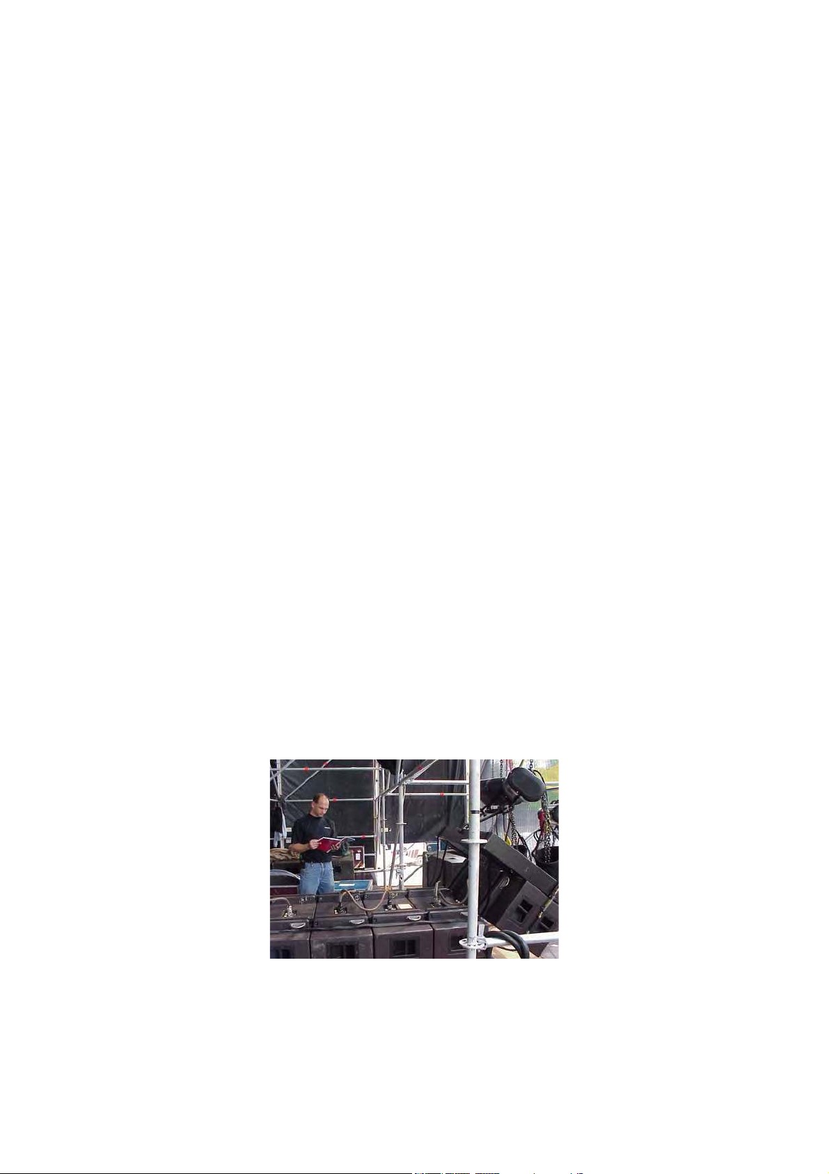
In the past, conventional horn-loaded trapezoidal loudspeakers were typically assembled in fan-shaped
arrays according to the nominal horizontal coverage angle of each enclosure in an attempt to reduce
coverage overlap that causes chaotic interference. With this type of arrangement, the optimum clarity
available in one direction could only be provided by the individual enclosure facing in this direction.
Attempts at “flattening the array” to achieve greater throw and higher SPLs resulted in severe
interference in an uncontrolled way, affecting coverage, pattern control, intelligibility and overall
sound quality. Even when arrayed according to specification (always an ''optimum'' compromise since
the polar response of individual horns varies with frequency), the sound waves radiated by individual
horn-loaded loudspeakers do not couple coherently thus the conventional system approach is
fundamentally flawed (see Appendix 1). Furthermore, the chaotic sound fields created by interfering
sound sources waste acoustic energy, thus requiring more power than a single, coherent source
would in order to obtain the same SPL.
As an illustration of this, imagine throwing some pebbles into a pool of water. If one pebble is thrown
into the water, a circular wave will expand concentrically from the point where it entered. If a handful
of pebbles are thrown into the water, we observe the equivalent of a chaotic wavefront. If we throw
in a single larger stone, having total size and weight equal to the handful of pebbles, then we again see
a coherent circular wave as for the case of the single pebble — only now with a much larger
amplitude. If all of the individual pebbles could be glued together, this would provide the same effect
as the larger stone...
This illustrates the thinking behind V-DOSC: if we can build a single sound source from a number of
individual speakers that can be separated for transport and handling, then we have achieved our goal,
i.e., to create a modular sound reinforcement system where the individual loudspeaker enclosures
couple correctly when arrayed together so that the system behaves as the equivalent of a coherent
line source array. This was the initial specification at the outset of the V-DOSC R&D program - to
design a single sound source that was completely modular, predictable and adjustable.
L-ACOUSTICS V-DOSC Manual Version 4 6/29/2005 Page 11 of 158
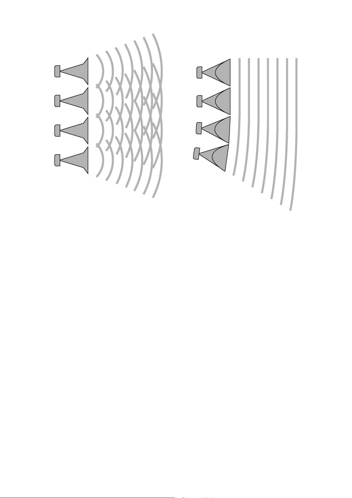
Figure 1: Wavefront interference for a conventional sound reinforcement system
compared to a sculptured V-DOSC wavefront
WAVEFRONT SCULPTURE TECHNOLOGY BACKGROUND
As early as 1988, a preliminary system named "Incremental" had proven the feasibility of Wavefront
Sculpture Technology. From this experimental concept, further theoretical research was conducted
by Professor Marcel Urban and Dr. Christian Heil and findings were published in 1992 (“Sound Fields
Radiated by Multiple Sound Source Arrays”, AES #3269).
The theory that was developed defines the acoustic coupling conditions for effectively arraying
individual sound sources. Relevant parameters include: wavelength, the shape and surface area of each
source, the curvature of the wavefront radiated by each source and the source separation.
WST coupling conditions can be summarized as follows:
An assembly of individual sound sources arrayed with regular separation between the sources on a plane or
curved, continuous surface is equivalent to a single sound source having the same dimensions as the total
assembly if, and only if, one of the two following conditions is fulfilled:
1) Shape: The combined surface area of the wavefronts radiated by the individual sources of the array fills at
least 80% of the target radiating surface area (see also Condition 3)
2) Frequency: The source separation, defined as the distance between acoustic centers of the individual
sources, is smaller than half the wavelength at all frequencies over the bandwidth of operation (generally,
this criteria is satisfied at lower frequencies since wavelengths are sufficiently large)
These two conditions form the basis of Wavefront Sculpture Technology (WST).
L-ACOUSTICS V-DOSC Manual Version 4 6/29/2005 Page 12 of 158
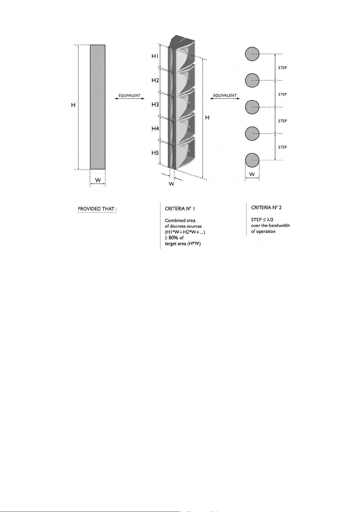
Figure 2: Wavefront Sculpture Technology Conditions 1 and 2 Illustrated
Additional conditions were published in the Audio Engineering Society journal paper ''Wavefront
Sculpture Technology'', JAES Vol. 51, No. 10, October 2003. The first two WST conditions were rederived (based on an intuitive approach using Fresnel analysis) and in addition it was shown that:
3) Deviation from the ideal, target wavefront (flat or curved) radiated by individual sources of the array
must be less than a quarter wavelength at the highest operating frequency (this corresponds to less than 5
mm of variation at 16 kHz)
4) For curved arrays, enclosure site angles should vary in inverse proportion to the listener distance
(geometrically this is equivalent to shaping variable curvature arrays to provide equal spacing of individual
enclosure site angle impacts on the audience listening plane)
5) Limits exist concerning the vertical height of each enclosure, the minimum allowed listener distance and
the angles that are allowed between enclosures.
The key to satisfying WST conditions at higher frequencies is a proprietary L-ACOUSTICS waveguide
®
that is used to load a conventional compression driver. This DOSC
waveguide was invented by Dr.
Christian Heil and is patented world-wide (see Appendix 4). DOSC stands for ”Diffuseur d’Onde
Sonore Cylindrique” – in English this means Cylindrical Sound Wave Generator (note: the “V” in VDOSC refers to the V-shaped acoustic lens configuration employed for the mid section). Essentially,
st
the DOSC waveguide permits fulfillment of the 1
L-ACOUSTICS V-DOSC Manual Version 4 6/29/2005 Page 13 of 158
and 3rd WST conditions at higher frequencies.

V-DOSC: THE SOLUTION
V-DOSC is the first loudspeaker system designed based on the principles of WST and can be
considered as the first modern generation line source array. It should be stressed that there is a big
difference between a line source array
arrays on the market today. Whether a line array correctly behaves as a line source array depends on
the extent to which the 5 WST conditions outlined in ''Wavefront Sculpture Technology'', JAES Vol. 51,
No. 10, October 2003 are satisfied. This may seem like semantics, but there are scientific and
technical reasons why V-DOSC works (not marketing reasons!).
V-DOSC was designed as a system consisting of identical, vertically-arrayed loudspeakers that satisfy
WST conditions for angles of 0° to 5.5° between adjacent enclosures. Individual components are
physically arranged within each enclosure so as to meet WST conditions, frequency band-byfrequency band, when the enclosures are arrayed together. Each enclosure radiates a flat, isophase
(constant phase) wavefront, allowing the overall assembly to coherently couple as a single extended
line source. Since the angle of separation between adjacent enclosures is adjustable, the radiated
wavefront can be focussed by physically shaping the array. By satisfying WST criteria over the entire
audio bandwidth, the engineer or designer is provided with a "single" loudspeaker with well-defined
coverage and wavefront shape, thus allowing the geometrical distribution of energy to be precisely
installed to match the geometry of the audience seating area.
1
The internationally-patented
DOSC waveguide is the core technology in V-DOSC that allows the first
and third WST conditions to be satisfied for frequencies higher than 1.3 kHz, i.e., the wavefronts
generated by individual DOSC waveguides are planar and their combined surface area accounts for at
least 80% of the target radiating surface area provided the angle between adjacent enclosures is less
than 5.5 degrees.
(such as V-DOSC, dV-DOSC, KUDO or ARCS) and other line
For traditional horn-loaded systems, coherent summation is not possible at higher frequencies since
the wavelengths become progressively smaller than the physical separation between the acoustic
centres of horn and driver assemblies. Neither of the first two WST criteria can be satisfied and, as a
result, interference occurs throughout most of the high frequency range (see Appendix 1).
By comparison, a V-DOSC array is a full-spectrum, coherent loudspeaker system - even for the
highest frequencies. As with any speaker system, interference occurs, however for V-DOSC the main
difference is that within the defined coverage region the interference is constructive while outside it is
destructive (see Appendix 2). For more details on how V-DOSC satisfies WST criteria, please refer to
Appendix 3. For further information on the DOSC waveguide, please see Appendix 4.
V-DOSC enclosures are vertically arrayed in two or four characteristic "J"-shaped columns. Since
enclosures of the array couple coherently, the enclosures are physically smaller and fewer cabinets are
required in comparison with conventional systems. This makes V-DOSC very cost-effective for
touring sound applications where transport space and handling time means money. These properties
also make V-DOSC highly effective for fixed installation where compact size combined with
predictable coverage is important.
One of the key benefits of WST is the predictability of the radiated wavefront's shape. Horizontally,
the entire V-DOSC array has the same coverage as a single enclosure (90°). Vertically, the coverage is
equal to the sum of the angles used between individual enclosures of the array. Given this
predictability, vertical coverage can be quickly optimized to match the audience geometry using either
L-ACOUSTICS ARRAY or SOUNDVISION software. These convenient, user-friendly software
programs help the operator determine how to focus the wavefront so that tonal balance and sound
pressure levels are evenly distributed throughout the audience (WST rule #4). Using either of these
programs, array design can be conveniently performed and installation parameters determined on a
case-by-case basis to optimize coverage for each venue according to the audience geometry.
1
The DOSC waveguide is registered under European patent n°0331566 and North American patent n°5163167. Please see
Appendix 4 for a description of the DOSC waveguide.
L-ACOUSTICS V-DOSC Manual Version 4 6/29/2005 Page 14 of 158
The configuration of transducers in V-DOSC is symmetrical with respect to the plane of propagation
of the radiated wavefront, i.e., the plane bisecting the horizontal coverage angle. High frequency
transducers loaded by DOSC waveguides are located in the middle, mid frequency transducers are on
both sides of the high section, and low frequency transducers are laterally positioned on both ends.
Such a configuration is described as having coplanar symmetry
.
Coplanar symmetry is the cylindrical domain equivalent of the coaxial arrangement* for individual
sound sources. Essentially, coplanar symmetry provides even coverage at any listening angle over a VDOSC array’s 90° horizontal coverage pattern, eliminating off-axis cancellations and polar lobing
effects at crossover frequencies. Coplanar symmetry produces a stable, symmetric horizontal
coverage pattern allowing simple, easy-to-use software tools to be used for horizontal coverage
prediction. Psychoacoustically, coplanar symmetry is largely responsible for the exceptional stereo
imaging properties that are characteristic of V-DOSC. Other practical benefits of the coplanar
symmetric configuration include the fact that there is no need to fly mirror-imaged L/R arrays plus
rigging issues are further simplified since the enclosure’s centre of gravity is also symmetric.
Figure 3: Coplanar Symmetry of V-DOSC
*
Distributed sound reinforcement using coaxial loudspeaker technology is L-ACOUSTICS’ other approach to sound
reinforcement. Either we respect WST criteria to obtain coherent coupling between individual sources and create a
single coherent line source (as for V-DOSC, dV-DOSC, KUDO, ARCS) or we separate individual, coherent sources
(MTD or XT coaxial loudspeakers) in a manner so that desired audience coverage is achieved while the effects of
audible interference are reduced. For more details on the benefits of coaxial loudspeaker technology and distributed
sound design techniques, please refer to the MTD or XT User Manuals (available for download on:
acoustics.com).
L-ACOUSTICS V-DOSC Manual Version 4 6/29/2005 Page 15 of 158
www.l-
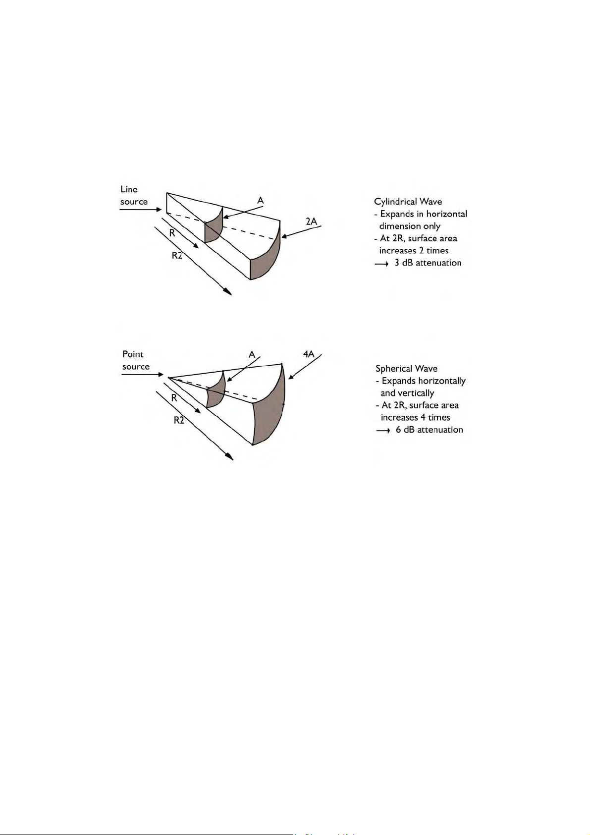
Apart from coverage precision and predictability, another significant benefit of V-DOSC is the fact that
the system effectively extends the nearfield region at higher frequencies (the nearfield is defined as the
region where cylindrical wavefront propagation applies and the farfield is the region where spherical
wavefront propagation occurs – see Appendix 5 for further details).
As pictured in Figure 4, cylindrical wave propagation results in a 3 dB reduction in SPL with doubling
of distance as opposed to the 6 dB reduction that is typical of conventional systems that radiate
spherical wavefronts.
Figure 4: Cylindrical versus spherical wave propagation
Due to it’s ability to generate cylindrical wavefronts, V-DOSC has different attenuation properties
than conventional systems and should not be evaluated in terms of the classical "$ / kilowatt"-ratio.
Comparing SPL predictions according to standard calculations is also not meaningful since V-DOSC
produces a combination of cylindrical and spherical wavefront propagation that must be evaluated
using specific calculations.
Aside: Conventional modeling techniques cannot accurately simulate WST-based systems such as ARCS,
KUDO, dV-DOSC or V-DOSC. For WST-based products, L-ACOUSTICS has worked with the developers of
EASE and CATT to integrate proprietary SOUNDVISION modeling techniques into these industry-standard
room acoustics modeling programs.
When curved V-DOSC arrays are employed there is a combination of cylindrical and spherical
propagation. This combined propagation, together with the actual shape of the audience allows the
wavefront to be focused so that tonal balance and sound pressure levels are evenly distributed
throughout the listening area. Although pure cylindrical wave propagation is not always in effect, 3 dB
reduction with doubling of distance can still be obtained along with extension of the nearfield if WST
Condition 4 is respected - this is an important aspect of WST and the reason why correct focus of VDOSC on the audience is so important.
Psychoacoustically, nearfield extension allows one to walk a considerable distance from a V-DOSC
system with only a small difference in SPL due to the system’s unconventional attenuation rate.
Effectively, more of the audience experiences nearfield listening, enjoying higher fidelity, improved
L-ACOUSTICS V-DOSC Manual Version 4 6/29/2005 Page 16 of 158
stereo imaging and exceptional clarity. Subjectively, the loudspeakers seem much closer than they are
physically and the sound is ''in your face''. This helps to improve image localization towards the action
on stage - not the loudspeaker arrays. Practically, nearfield extension also means that extreme sound
pressure levels are not required close to the system in order to obtain acceptable SPLs further back in
the venue - this is a highly desirable property that results in reduced potential for hearing loss for both
audiences and engineers alike.
Nearfield extension, combined with the precision and predictability of V-DOSC coverage is also
effective in “pushing back” the critical distance in highly reverberant spaces (critical distance is defined
as the distance in a venue where the energy of the direct sound coming from the system is equal to
the reverberant energy coming from the room). In many situations, it is extremely important to keep
energy off the roof, for example in arenas or covered outdoor amphitheatres (sheds). If we can excite
less of the reverberant energy in the room and focus more energy on the audience, we can effectively
move back the critical distance in a given room while offering more of the audience a nearfield
listening experience. Given the well-defined vertical coverage of V-DOSC, the benefits of WST
become immediately obvious in comparison with conventional systems when working in difficult,
reverberant rooms.
Finally, another benefit of WST is the high degree of SPL rejection obtained outside of the defined
coverage pattern. Nominally higher than 20 dB, this permits the installation of a V-DOSC system
behind or above microphones with exceptionally high feedback immunity. Monitor engineers also
enjoy working with V-DOSC FOH systems since there is very little backwave on stage - even at lower
frequencies (for larger arrays of up to 16 enclosures, vertical pattern control is obtained down to as
low as 80 Hz). High SPL rejection outside of the defined coverage region also makes V-DOSC an
excellent solution in situations where environmental noise control is an issue, for example, in situations
where outdoor venues are located close to residential areas.
The accuracy, flexibility and predictability inherent in the V-DOSC approach to sound reinforcement
has opened up many new horizons for sound design.
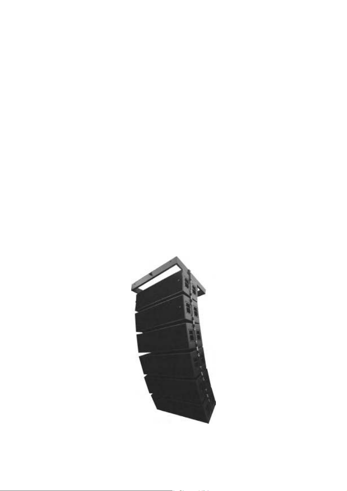
Figure 5: V-DOSC Array
L-ACOUSTICS V-DOSC Manual Version 4 6/29/2005 Page 17 of 158

V-DOSC TRAINING AND QUALIFICATIONS
V-DOSC is an innovative design based on a new approach to sound reinforcement that can provide
predictable results to the extent that no other existing system can. However, achieving the desired
result requires following a methodical procedure which may at first seem unusual to some sound
designers and engineers. Hopefully, most of you will embrace this technology and approach V-DOSC
with an open mind, excited by the possibilities that such a system allows.
However, it can be “hard to teach an old dog new tricks”. For those of you in this category, the first
step to take is to forget your experience with other systems and overcome your biases. Try to accept
the fact that THIS SYSTEM BEHAVES DIFFERENTLY! Once you understand the procedures involved
in working with V-DOSC, you will save time and - more importantly - obtain better, more predictable
results.V-DOSC cannot be left in the hands of someone who has no experience with the system even if that person has great skills and experience with respect to other systems. A V-DOSC operator
needs specialized training and there are two levels of qualification:
QUALIFIED V-DOSC TECHNICIAN (QVT)
The tasks of a “Qualified V-DOSC Technician” are: equipment preparation, array design using ARRAY
or SOUNDVISION software (based on room dimensions that are either measured on-site or
determined from architectural drawings), system installation (rigging, assembly, cabling, system focus,
preset selection and drive rack configuration), system testing/tuning and assisting the FOH mix
engineer. The QVT is a sound technician with demonstrated ability who has been chosen for his or
her technical expertise by a given V-DOSC Network Partner.
To be considered a Qualified V-DOSC Technician, the candidate must meet the following criteria:
♦ Participated in a 3 day V-DOSC training session on theory and rigging
♦ Recommended by a recognized CVE (see below) or an official V-DOSC Network representative
CERTIFIED V-DOSC ENGINEER (CVE)
The higher level of qualification is ''Certified V-DOSC Engineer'' or CVE. In addition to satisfying the
mission statement for QVTs, the CVE has further expertise in the areas of: sound design and system
measurement as well as extensive real world experience with V-DOSC. The CVE has a complete
theoretical understanding of all WST-based systems (including V-DOSC, ARCS, KUDO, dV-DOSC)
with a full grasp of the operating theories and principles behind all systems.
Other requirements include: demonstrated fluency in ARRAY and SOUNDVISION software; use of
advanced measurement tools (SMAART, WinMLS, MLSSA or equivalent) for system alignment and
tuning; full understanding of the finer points of system focus – for example: tensioning ratchet straps
using digital inclinometers, angle strap calibration; familiar with all preset libraries and software for all
supported DSP units; familiar with room measurement procedures using laser rangefinders and
inclinometers.
The CVE is capable of recommending, endorsing and supervising QVTs during their apprenticeship
period towards becoming a full CVE. In some cases, CVEs may also conduct V-DOSC training sessions
provided that they have been factory-certified as a V-DOSC Trainer.
To be included in the official list that is distributed to members of the V-DOSC Network, the CVE
candidate must meet the following criteria:
♦ Participated in a 3 day V-DOSC training session on theory and rigging
♦ Recommended by a recognized CVE or an official V-DOSC Network representative
♦ Known and certified by an official representative of L-ACOUSTICS
The Qualified V-DOSC Technician and Certified V-DOSC Engineer are important representatives of
the V-DOSC Network. While the V-DOSC Network provides V-DOSC on a rental basis, it is the
QVT or CVE who accompanies the system at each installation to ensure that system performance is
optimal. We hope that you will carefully follow the guidelines presented in this manual - it is in
everyone’s best interest that V-DOSC is deployed correctly and optimally in the field.
L-ACOUSTICS V-DOSC Manual Version 4 6/29/2005 Page 18 of 158

1. THE V-DOSC SYSTEM STANDARD
V-DOSC is a complete, self-contained FOH sound reinforcement system consisting of V-DOSC
enclosures and accessories, rigging hardware, SB218 subwoofers, approved digital signal processors
with OEM factory presets, L-ACOUSTICS LA48a power amplifiers, power amplifier racks, PADO2a
or PADO4a panels, CO6 or CO24 signal distribution panels, loudspeaker and signal distribution
cables. V-DOSC system elements have been carefully selected by L-ACOUSTICS for their specific
quality and long term reliability.
The benefits of a system standard include:
Cross rental compatibility between V-DOSC Network Partners
High standards of quality control
Consistent system performance worldwide
Reduced procurement time (no need to build panels, racks, etc)
Long term, common experience shared by QVTs and CVEs
Enhanced end user confidence (artist, FOH engineer, production)
The V-DOSC system standard does not include chain motors, mains distribution or external handling
gear, nor does it include upstream signal mixing and processing equipment. In general, the V-DOSC
system is capable of producing sound from a line-level signal in any concert situation.
System block diagrams are presented below to provide an overview of system connection and signal
flow. This is followed by an identification of the individual elements of the system and more detailed
descriptions in Sections 1.2 through 1.7.
Please note that specific multi-conductor connector selection for system drive remains open for the
user to define although L-ACOUSTICS does offer a specific connector type that is supplied with
turnkey systems. L-ACOUSTICS recognizes the fact that multi-conductor snakes and connectors
represent a significant investment and many users already have their own internal standard that they
must adhere to. Therefore, this part of the system standard remains flexible.
System elements that must remain standard in order to ensure compatibility include: digital signal
processors; OEM factory presets; channel assignments for signal distribution; power amplifiers; and
power amplifier rack panels.
General block diagram representations of V-DOSC system components, cabling and signal flow are
given below in Figures 6-8. Please refer to these block diagrams for a system overview.
NOTE: V-DOSC systems that do not comply with the system standard are considered non-approved by LACOUSTICS. For the case of non-standard systems, L-ACOUSTICS does not accept responsibility for misuse
or misoperation and in some cases warranty coverage may be considered void.
L-ACOUSTICS strongly encourages all users to comply with the recommended standard as closely as
possible in order to maintain approved status.
L-ACOUSTICS V-DOSC Manual Version 4 6/29/2005 Page 19 of 158
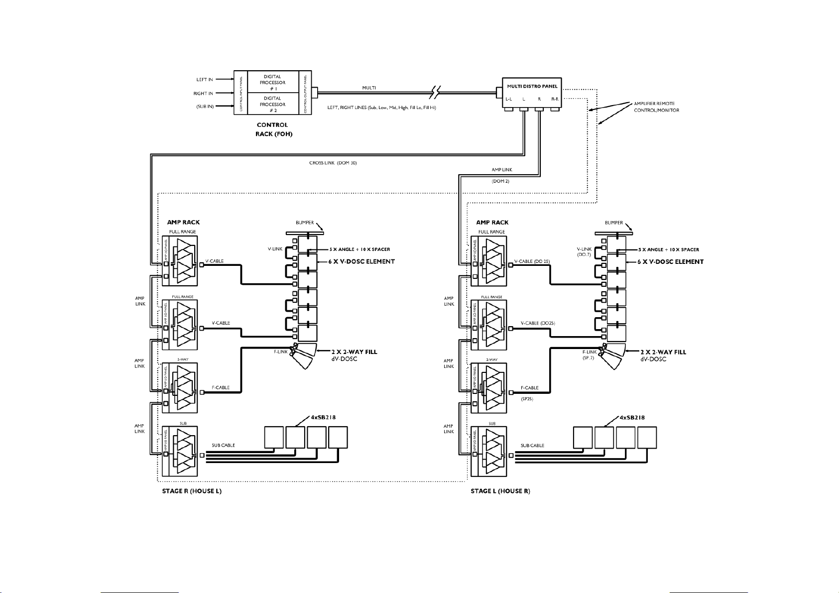
Figure 6: V-DOSC System Block Diagram
L-ACOUSTICS V-DOSC Manual Version 4 6/29/2005 Page 20 of 158
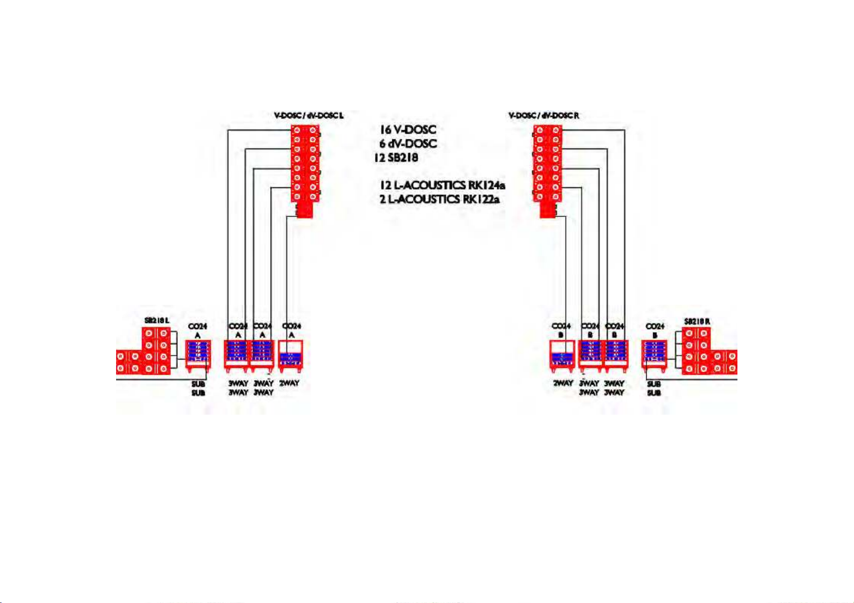
Figure 7: Example LR System Configuration
L-ACOUSTICS V-DOSC Manual Version 4 6/29/2005 Page 21 of 158
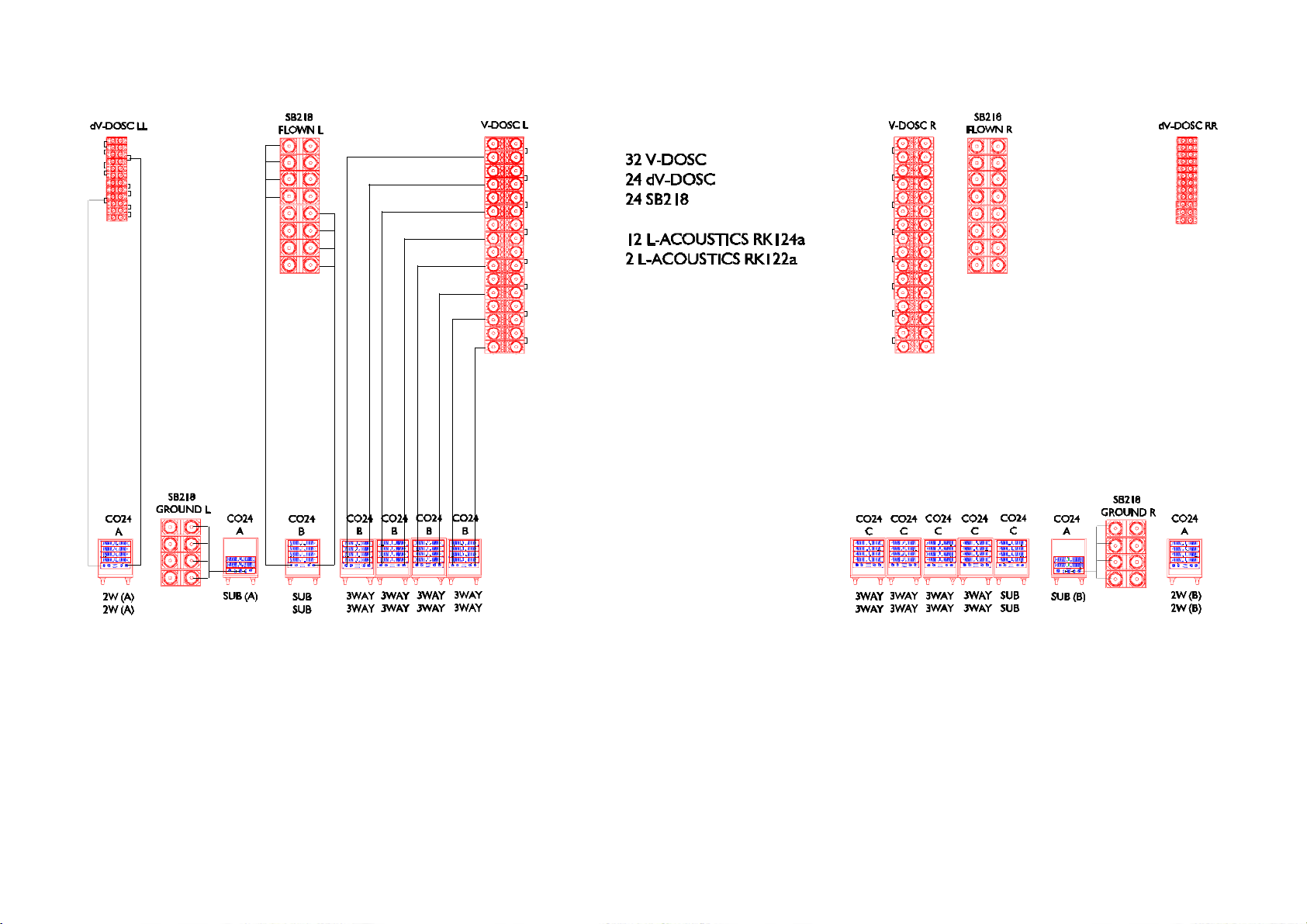
Figure 8: Example LR System Plus Offstage Fill Configuration
(additional distributed front fill or stereo infill system recommended)
L-ACOUSTICS V-DOSC Manual Version 4 6/29/2005 Page 22 of 158
1.1 V-DOSC SYSTEM COMPONENTS
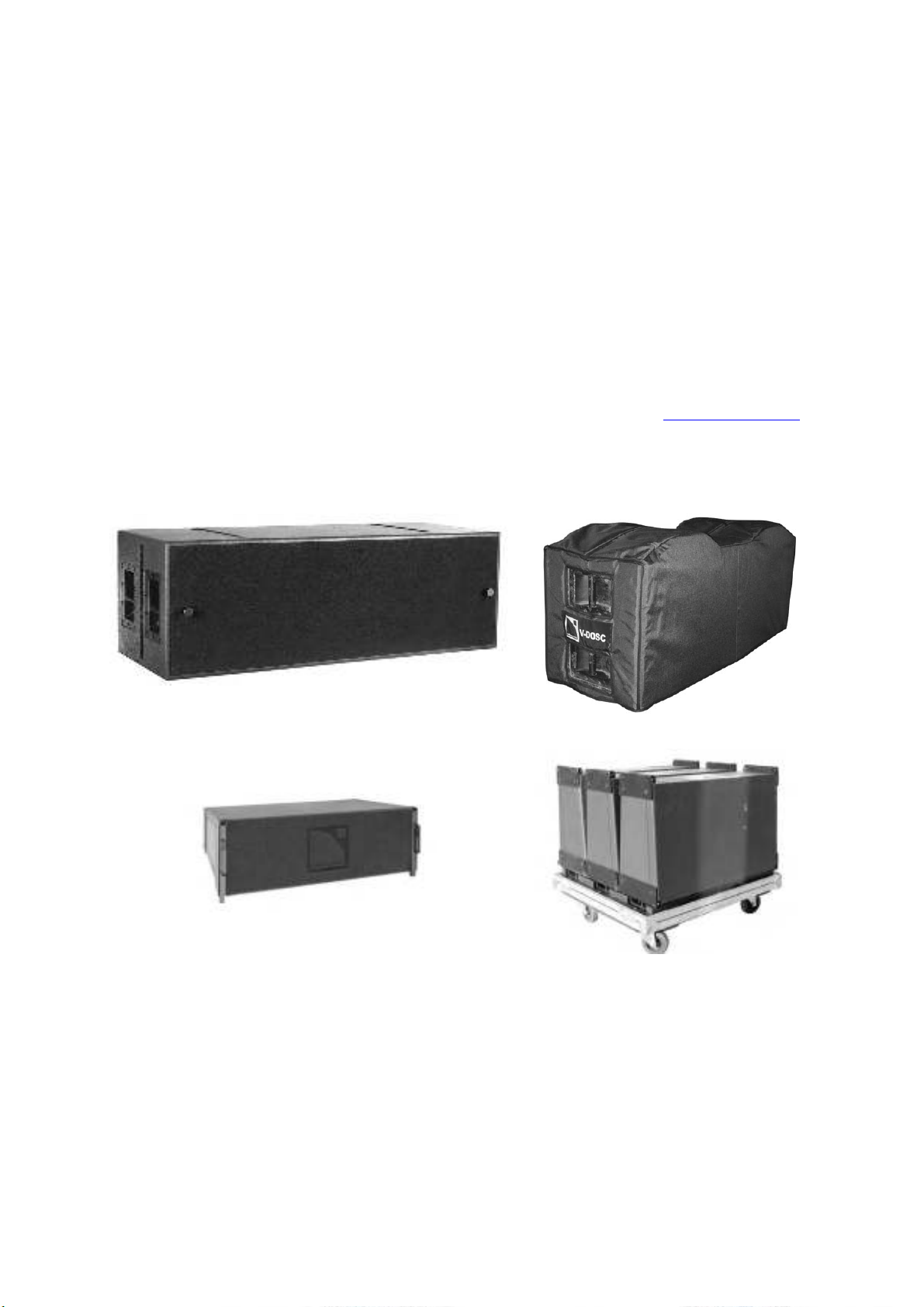
LOUDSPEAKER ENCLOSURES
(1) V-DOSC
Full-range active 3-way loudspeaker enclosure, meeting WST criteria, with coplanar symmetric
arrangement of loudspeaker components. Includes removable front dolly (not shown)
(2) DOSC-COV
Protective cover for V-DOSC enclosures (comes in pairs). Constructed of rugged cordura
material and padded for extra protection
(3) dV-DOSC
Active 2-way loudspeaker enclosure, meeting WST criteria, with coplanar symmetric
arrangement of loudspeaker components. Used with V-DOSC for down-fill, up-fill/long-throw,
offstage fill, stereo in-fill or distributed front fill.
Note: for full details, see the dV-DOSC user manual (available for download on:
(4) FLIGHT-dV
Flight case for transport of three dV-DOSC enclosures
V-DOSC
www.l-acoustics.com
DOSCOVx2
)
dV-DOSC
Figure 9: V-DOSC system loudspeakers plus accessories
L-ACOUSTICS V-DOSC Manual Version 4 6/29/2005 Page 23 of 158
FLIGHT-dV
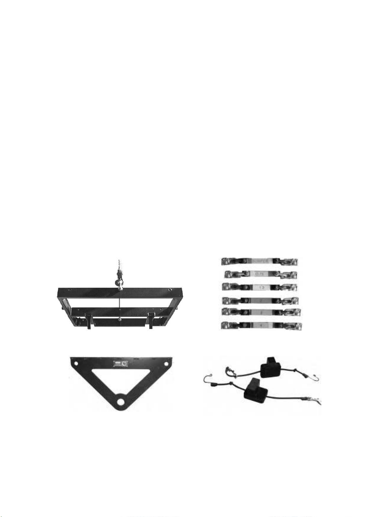
RIGGING ACCESSORIES
(5) BUMP2
Flying bumper for rigging a V-DOSC array up to 16 enclosures deep. Can also be inverted and
used as an adjustable base for stacking a V-DOSC array
(6) BUMPDELTA
Delta plate used to attach two motors to BUMP2, allowing for pan adjustment of a flown VDOSC array
(7) ANGLE STRAPS
Used to provide spacing between V-DOSC enclosures when stacked or flown. Values: 0.75° or
5.5°; 1.3°; 2°; 3°; 4° (Part Codes: BUMP24; BUMP251; BUMP25; BUMP26; BUMP27)
(8) SPACER
Used with ANGLE STRAPS to provide the desired spacing between V-DOSC enclosures when
stacked or flown (Part Codes; SPAC251=1.3°; SPAC25=2°; SPAC26=3°; SPAC27=4°;
SPAC28 =5.5° for use with corresponding BUMPxx)
(9) CHARIOT
Transportation chariot for 2 x BUMP2, 2 x BUMPSUB, ANGLE straps, ratchet straps,
screwjacks, shackles and other rigging accessories
(10) dV-BUMP
Flying bumper for rigging dV-DOSC and/or dV-SUB. When combined with V-DOSC BUMP2,
can be used for rigging dV-DOSC on top of V-DOSC or for stacking dV-DOSC.
(11) dV-DOWN
Pair of rigging adapters for installing dV-DOSC underneath V-DOSC for down-fill applications
BUMP2
ANGLE STRAPS
BUMPDELTA
L-ACOUSTICS V-DOSC Manual Version 4 6/29/2005 Page 24 of 158
SPACER
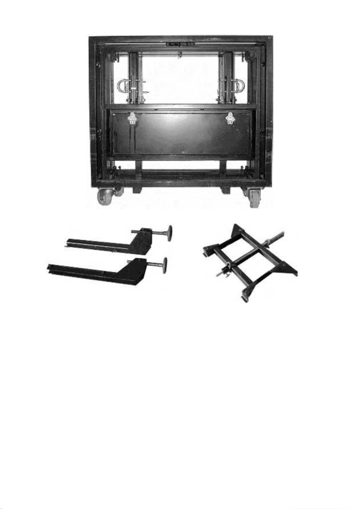
dV-DOWN
CHARIOT
dV-BUMP
Figure 10: V-DOSC Rigging Accessories
L-ACOUSTICS V-DOSC Manual Version 4 6/29/2005 Page 25 of 158
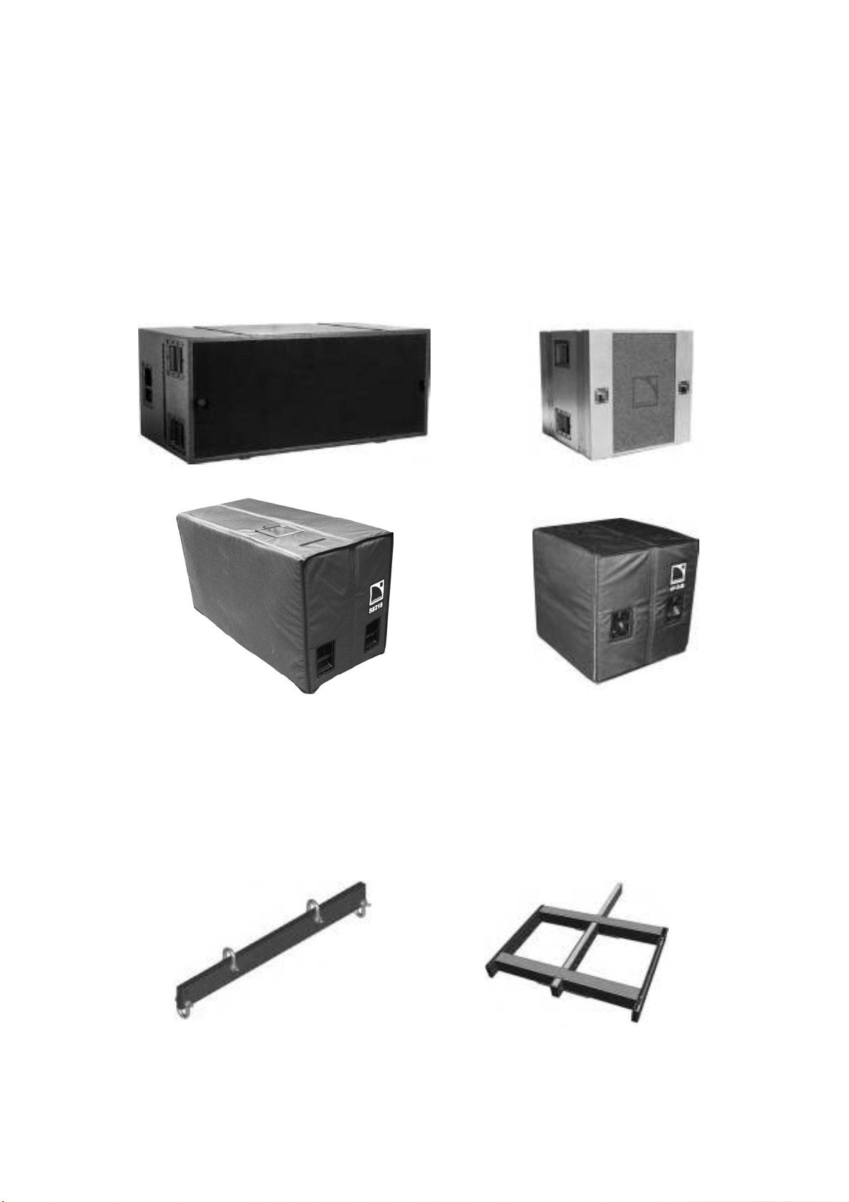
SUBWOOFER ENCLOSURES
(12) SB218
Front-loaded, bass-reflex, dual 18’’ subwoofer for high level, extended bandwidth. Optional
removable front dolly (not shown) recommended for touring applications.
(13) SUBCOV
Protective cover for SB218 enclosures (comes in pairs)
(14) dV-SUB
Dual-vented bandpass-loaded, triple 15” subwoofer for high level, low frequency extension.
Optional removable front dolly (not shown) recommended for touring applications.
(15) dV-SUBCOV
Protective cover for dV-SUB enclosures (comes in pairs)
SB218
dV-SUB
SUB COV
Figure 11: V-DOSC Subwoofer Options
dVSUB COV
SUBWOOFER RIGGING ACCESSORIES
(16) BUMPSUB
Flying bar for rigging up to eight SB218 enclosures deep in a vertical line array
(17) dV-BUMP2
Flying bumper for rigging up to six dV-SUB enclosures deep in a vertical line array (also an
alternative to dV-BUMP for rigging dV-DOSC and/or dV-SUB)
BUMPSUB
Figure 12: Subwoofer Rigging Accessories
L-ACOUSTICS V-DOSC Manual Version 4 6/29/2005 Page 26 of 158
dV-BUMP2

AMPLIFICATION
(18) L-ACOUSTICS LA48a
Compact, light weight two-channel power amplifier (2 rack units, 10 kg), 1300 watts per channel into
8 ohms, 2300 watts per channel into 4 ohms.
Figure 13: L-ACOUSTICS LA48a Power Amplifier
Note: for full details see the LA48a user manual (available for download on:
www.l-acoustics.com)
AMPLIFIER RACKS
(19) RK12U
12 rack unit amplifier rack (empty). Light-weight aluminum space frame construction, internal
shock mounting, standard rack rails, provision for rear support of amplifiers, transparent lexan
doors that store inside the rack, high impact resistance polyethylene cover (no external case
required). Recessed Aeroquip flytrack sections for flown applications.
(20) RK122a
RK12U supplied with PADO2a, PADOSEC, 2U drawer, 2U blank panel, rear support kit for 2
L-ACOUSTICS LA48a power amplifiers (LA48a power amplifiers not included).
(21) RK124a
RK12U supplied with PADO4a, PADOSEC, rear support kit for 4 L-ACOUSTICS LA48a power
amplifiers (LA48a power amplifiers not included).
(22) PADO2a AMP PANEL
Amplifier panel supplied with RK122a suitable for 2 amplifier rack configuration. Single 8 pin
female CA-COM connector for loudspeaker connection (in parallel with 4x Speakon
connectors), two male 19 pin CA-COM connectors for signal distribution (input/through),
COMB connector (for selecting 2-way, 3-way or subwoofer operating modes); 4x male XLR
and 4x Speakon fanouts on the internal side (for connecting to amplifier inputs and outputs).
Note: PADO stands for PA
TCH DOSC
(23) PADO4a AMP PANEL
Amplifier panel supplied with RK124a suitable for 4 amplifier rack configuration. Dual 8 pin
female CA-COM connectors for loudspeaker connection, two male 19 pin CA-COM
connectors for signal distribution (input/through), 2x COMB connectors (for selecting 2-way, 3way or subwoofer operating modes); 2 pairs of 4x male XLR and 4x Speakon fanouts on the
internal side (for connecting to amplifier inputs and outputs).
(24) COMB CONNECTOR
Routes desired input lines from the male 19 pin CA-COM connector to the appropriate
amplifier inputs allowing RK122a or RK124a amplifier racks to be configured in 2-way (dVDOSC, ARCS), 3-way (V-DOSC, KUDO) or subwoofer (SB218) operating modes (COMB
connectors: D2WAY, D3WAY and DSUB, respectively). Additional COMB connectors are
available for use with 2- or 3-way format systems (D2WA, D2WB, D2WSTEREO, D3WA,
D3WB, DSUBA, DSUBB) and a COMB connector kit for subwoofer array signal processing or
for powering passive enclosures (DSUBTK).
(25) PADOSEC
Mains distribution panel, 32 amp connector, 5x AC receptacles
L-ACOUSTICS V-DOSC Manual Version 4 6/29/2005 Page 27 of 158

RK12U
PADOSEC
RK122a
PADO2a
COMB CONNECTOR
PADO4a
RK124a
Figure 14: Amplifier Rack Options and Accessories
L-ACOUSTICS V-DOSC Manual Version 4 6/29/2005 Page 28 of 158

SIGNAL DISTRIBUTION AND CABLING
(26) CO6 CONTROL OUTPUT PANEL
Control Output Panel for use with a single 2 in x 6 out (or 3 x 6) digital signal processor (DSP)
to create a compact, modular drive rack or for mounting in RK12U amplifier racks along with
amplifiers and a DSP unit for standalone master rack applications. DSP outputs are connected
to the 6x female XLR patch bay on the rear side of the CO6 panel and then assigned to the
front panel 19-pin CACOM connector to provide a 6 channel multi-conductor return snake
system when used with DOM30 Cross Link cables.
(27) CO24 CONTROL OUTPUT PANEL
Control Output Panel for use with four 2 in x 6 out (or 3 x 6) DSPs to create a system drive
rack: 1x 84 pin MASS connector; 4x 19 pin male CA-COM connectors; 24x female XLR inputs
on the internal side; 1x male/female 4-pin XLR pair for amplifier remote control/monitoring.
Used for connecting DSP outputs and amplifier remote control/monitoring to MC28100 MULTI
return snake lines.
(28) MD24 MULTI DISTRO PANEL
Stage distribution panel with 1x 84 pin MASS connector (for connection of MULTI return snake
from FOH), 4x 19 pin male CA-COM (for distribution of Left-Left, Left, Right, Right-Right signal
lines), 1x male/female 4-pin XLR pair (for distribution of amplifier remote control).
(29) MC28100 MULTI-CONDUCTOR CABLE
24 pair multi-conductor return snake, 100 m (325 ft) length, fitted with 84 pin MASS connectors
at each end (used for connecting CONTROL OUTPUT panel, typically located at FOH, to
MULTI DISTRO panel for signal distribution to the amplifier racks)
(30) PCMCIA CARDS
Contain OEM factory preset data for programming DSP units (PCM224V, PCM226V and
PCM366V for XTA DP224, DP226 and BSS 366, respectively). Other approved DSPs are
programmed via computer download of preset data (Lake Contour, BSS Soundweb).
(31) DOM2 AMP LINK CABLE
6 pair multi-conductor cable, 2 m (6.5 ft) length, with 2x female 19 pin bayonet CA-COM
connectors (for distributing signal from CO6 or MULTI DISTRO panels to amplifier racks and
for linking AMP RACKS)
(32) DOM30 CROSS LINK CABLE
6 pair multi-conductor cable, 30 m (100 ft) length, with 2x female 19 pin bayonet CA-COM
connectors (for cross-stage connection from MULTI DISTRO panel to amplifier racks or for use
as a return snake for smaller system configurations)
(33) DOMP ADAPTER
19 pin male/male CA-COM adapter (for connecting two AMP LINK or CROSS LINK cables
when longer lengths are required)
(34) DOMM LINK BREAKOUT
Multipair cable adapter with 1x female 19 pin CA-COM connector at one end, 6x male XLR
connectors at the other (used as a LINK cable breakout for patching and testing purposes)
(35) DOMF LINK-BREAKOUT
Multipair cable adapter with 1x female 19 pin CA-COM connector at one end, 6x female XLR
connectors at the other (used as a LINK cable breakout for patching and testing purposes).
Note: Parts nomenclature is as follows:
DOM = DO
DOMP = DO
L-ACOUSTICS V-DOSC Manual Version 4 6/29/2005 Page 29 of 158
SC Modulation
SC Modulation Prolongateur (French for extender)
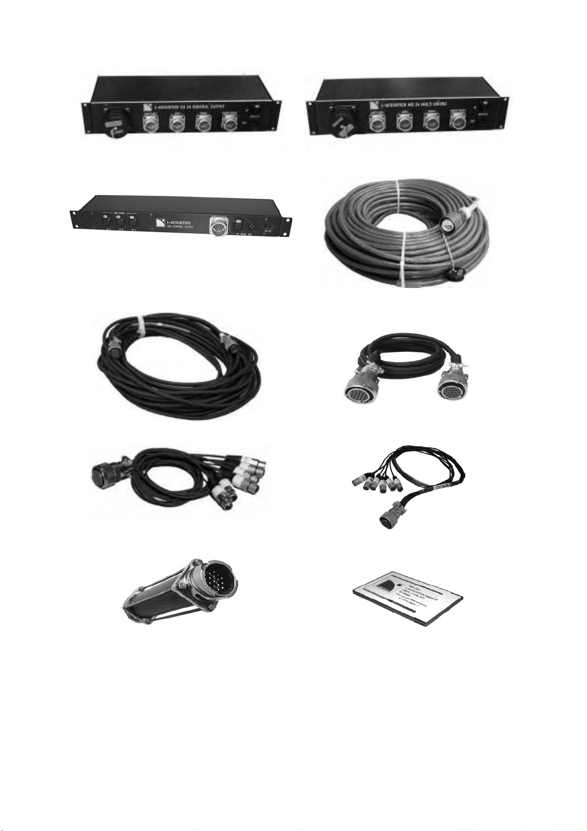
CO24 CONTROL OUTPUT
CO6 CONTROL OUTPUT
DOM30 CROSS LINK
MD24 MULTI DISTRO
MC28100 MULTI
DOM2 AMP LINK
DOMF LINK BREAKOUT
DOMM LINK BREAKOUT
DOMP LINK EXTEND
Figure 15: Signal distribution and cabling
PCMCIA CARD
L-ACOUSTICS V-DOSC Manual Version 4 6/29/2005 Page 30 of 158
 Loading...