

L-Acoustics MTD Series, MTD108a, MTD112b, MTD115b Operator's Manual

Version 1.2
December 2004
L-ACOUSTICS MTD LINE
MTD108a, MTD112b, MTD115b
OPERATOR MANUAL

L-ACOUSTICS MTD Manual V1.2 11/30/2004 1
FOREWORD
Thank you for purchasing the MTD108a, MTD112b or MTD115b sound reinforcement system.
This manual is intended to provide you with the information you require to install and operate your
MTD loudspeaker enclosure in a wide variety of professional sound reinforcement applications.
Specific information and recommendations are included regarding system design, sound design and
installation. We are confident that the information provided in this manual will be sufficient for most
applications, however, should you require further assistance your distributor or L-ACOUSTICS
®
are
available to provide additional technical support.
MANUAL ORGANIZATION
The Introduction gives a brief presentation of coaxial technology and the MTD line.
Chapter 1 introduces MTD108a, MTD112b, MTD115b loudspeaker enclosures plus accessories
Chapter 2 discusses MTD power amplification and cabling
Chapter 3 describes MTD processing using LLC analog controllers
Chapter 4 provides examples of MTD packaging
Chapter 5 discusses sound design aspects
Chapter 6 outlines MTD installation procedures
Chapter 7 discusses MTD system operation and maintenance procedures
Chapter 8 provides MTD108a, MTD112b and MTD115b specifications

L-ACOUSTICS MTD Manual V1.2 11/30/2004 2

L-ACOUSTICS MTD Manual V1.2 11/30/2004 3
TABLE OF CONTENTS
FOREWORD.............................................................................................................................................. 1
MANUAL ORGANIZATION....................................................................................................................1
TABLE OF CONTENTS............................................................................................................................3
LIST OF FIGURES..................................................................................................................................... 4
LIST OF TABLES ......................................................................................................................................5
0. INTRODUCTION ................................................................................................................................. 6
1. THE MTD SYSTEM...............................................................................................................................7
1.1 MTD SYSTEM COMPONENTS ..................................................................................................................... 7
1.2 MTD OVERVIEW ....................................................................................................................................... 12
1.3 MTD108a SPECIFICATIONS....................................................................................................................... 13
1.4 MTD112b SPECIFICATIONS....................................................................................................................... 14
1.5 MTD115b SPECIFICATIONS....................................................................................................................... 15
2. POWERING MTD ...............................................................................................................................16
2.1 POWERING MTD108a............................................................................................................................... 17
2.2 POWERING MTD112b .............................................................................................................................. 18
2.3 POWERING MTD115b (PASSIVE MODE)................................................................................................... 19
2.4 POWERING MTD115b (ACTIVE MODE).................................................................................................... 20
2.5 CONNECTORS AND CABLES ..................................................................................................................... 23
3. PROCESSING MTD............................................................................................................................24
3.1 L-ACOUSTICS MTD108 LLCa DESCRIPTION .............................................................................................. 24
3.2 L-ACOUSTICS LLC 112b-st DESCRIPTION.................................................................................................. 24
3.3 L-ACOUSTICS LLC 115b-st, LLC115b-2w DESCRIPTION.............................................................................25
4. MTD CONFIGURATIONS .................................................................................................................26
4.1 MTD108a FLOOR MONITOR SYSTEM ....................................................................................................... 27
4.2 MTD108a FOH SYSTEM (MONO SUBS) .................................................................................................... 28
4.3 MTD108a FOH SYSTEM (STEREO SUBS)................................................................................................... 29
4.4 MTD112b FLOOR MONITOR SYSTEM ....................................................................................................... 30
4.5 MTD112b FOH SYSTEM (MONO SUB)...................................................................................................... 31
4.6 MTD112b FOH SYSTEM (STEREO SUBS)................................................................................................... 32
4.7 MTD115b (PASSIVE) FLOOR MONITOR SYSTEM ....................................................................................... 33
4.8 MTD115b (PASSIVE) FOH SYSTEM (MONO SUB)...................................................................................... 34
4.9 MTD115b (PASSIVE) FOH SYSTEM (STEREO SUBS)................................................................................... 35
4.10 MTD115b (ACTIVE) FLOOR MONITOR SYSTEM......................................................................................36
4.11 MTD115b (ACTIVE) FOH SYSTEM (STEREO SB118 SUBS)....................................................................... 37
4.12 MTD115b (ACTIVE) FOH SYSTEM (STEREO SB218 SUBS)....................................................................... 38
5. SOUND DESIGN ................................................................................................................................39
5.1 APPLICATIONS ........................................................................................................................................... 39
5.2 AIMING MTD ENCLOSURES...................................................................................................................... 39
5.3 ARRAYING MTD ENCLOSURES.................................................................................................................. 40
5.4 PREDICTING MTD COVERAGE .................................................................................................................. 43
5.5 DISTRIBUTED SOUND REINFORCEMENT................................................................................................. 43
5.5.1 OVERHEAD DISTRIBUTED SYSTEMS ............................................................................................ 43
5.5.2 DELAY SYSTEMS .............................................................................................................................. 43
5.5.3 COMPLEMENTARY FILL ................................................................................................................. 44
5.6 FRONT-OF-HOUSE (FOH) APPLICATIONS ................................................................................................ 45
5.7 STAGE MONITORING................................................................................................................................ 46
5.8 USING MTD WITH SUBWOOFERS ........................................................................................................... 48
5.8.1 COMBINING MTD WITH SUBWOOFERS ..................................................................................... 49
5.8.2 GROUND STACKED SYSTEMS....................................................................................................... 49
5.8.3 SEPARATE FLOWN MTD WITH GROUND STACKED SUBWOOFERS ...................................... 50

L-ACOUSTICS MTD Manual V1.2 11/30/2004 4
6. INSTALLATION PROCEDURES .......................................................................................................51
6.1 ETR8 U-BRACKET ATTACHMENT(MTD108a) ........................................................................................... 51
6.2 ETR1, ETR2 U-BRACKET ATTACHMENT (MTD112b, MTD115b) ...............................................................52
6.3 OMNIMOUNT BRACKET ATTACHMENT (MTD112b, MTD115b) ..............................................................53
6.4 SAFETY RULES ........................................................................................................................................... 53
7. MTD SYSTEM OPERATION..............................................................................................................54
7.1 RECOMMENDED MAINTENANCE PROCEDURES ..................................................................................... 54
7.2 SPARE PARTS.............................................................................................................................................. 55
8. SPECIFICATIONS ..............................................................................................................................56
8.1 MTD108a SPECIFICATIONS....................................................................................................................... 56
8.2 MTD108LLCa SPECIFICATIONS ................................................................................................................. 59
8.3 MTD112b SPECIFICATIONS....................................................................................................................... 60
8.4 LLC112b-st SPECIFICATIONS ..................................................................................................................... 63
8.5 MTD115b SPECIFICATIONS....................................................................................................................... 64
8.6 LLC115b-st, LLC115b-2w SPECIFICATIONS................................................................................................ 67
LIST OF FIGURES
Figure 1: MTD System Components........................................................................................................9
Figure 2: MTD LLC Controllers .............................................................................................................11
Figure 3: MTD108a passive 2-way (8” LF + 1” HF) coaxial loudspeaker..............................................13
Figure 4: MTD112b passive 2-way (12” LF + 1.4” HF) coaxial loudspeaker ........................................14
Figure 5: MTD115b active/passive 2-way (15” LF + 1.4” HF) coaxial loudspeaker..............................15
Figure 6: MLS switches on the rear panel of L-ACOUSTICS LA24a, LA48a amplifiers.........................16
Figure 7a: MTD108a Floor Monitor System Block Diagram ..................................................................27
Figure 7b: MTD108a Floor Monitor System Cabling Detail...................................................................27
Figure 8a: MTD108a FOH System Block Diagram (mono subwoofers)................................................28
Figure 8b: MTD108a FOH System Cabling Detail (mono subwoofers).................................................28
Figure 9a: MTD108a FOH System Block Diagram (stereo subwoofers) ...............................................29
Figure 9b: MTD108a FOH System Cabling Detail (stereo subwoofers)................................................29
Figure 10a: MTD112b Floor Monitor System Block Diagram................................................................30
Figure 10b: MTD112b Floor Monitor System Cabling Detail ................................................................30
Figure 11a: MTD112b FOH System Block Diagram (mono subwoofers)..............................................31
Figure 11b: MTD112b FOH System Cabling Detail (mono subwoofers) ..............................................31
Figure 12a: MTD112b FOH System Block Diagram (stereo subwoofers).............................................32
Figure 12b: MTD112b FOH System Cabling Detail (stereo subwoofers) ............................................32
Figure 13a: MTD115b (passive) Floor Monitor System Block Diagram.................................................33
Figure 13b: MTD115b (passive) Floor Monitor System Cabling Detail .................................................33
Figure 14a: MTD115b (passive) FOH System Block Diagram (mono subwoofers) ..............................34
Figure 14b: MTD115b (passive) FOH System Cabling Detail (mono subwoofers) ...............................34
Figure 15a: MTD115b (passive) FOH System Block Diagram (stereo subwoofers)..............................35
Figure 15b: MTD112b (passive) FOH System Cabling Detail (stereo subwoofers) ..............................35
Figure 16a: MTD115b (active) Floor Monitor System Block Diagram...................................................36
Figure 16b: MTD115b (active) Floor Monitor System Cabling Detail ...................................................36
Figure 17a: MTD115b (active) FOH System Block Diagram (mono subwoofers).................................37
Figure 17b: MTD115b (active) FOH System Cabling Detail (mono subwoofers) ................................37
Figure 18a: MTD115b (active) FOH System Block Diagram (stereo subwoofers)................................38
Figure 18b: MTD112b (active) FOH System Cabling Detail (stereo subwoofers)................................38
Figure 19: General guidelines for aiming MTD enclosures.....................................................................40
Figure 20: SPL mappings at octave band frequencies for a single MTD enclosure ................................40
Figure 21: SPL mappings for two MTD enclosures with 0.5 metre spacing ..........................................41
Figure 22: SPL mappings for two MTD enclosures with 3 metre spacing .............................................41
Figure 23: General guidelines for arraying MTD enclosures. .................................................................42

L-ACOUSTICS MTD Manual V1.2 11/30/2004 5
Figure 24: SPL mappings for four MTD enclosures with 0.5 metre spacing. .........................................42
Figure 25: L-ACOUSTICS Subwoofer Continuous Unweighted SPL Comparison................................48
Figure 26: Illustration of subwoofer time alignment...............................................................................50
Figure 27: ETR8 U-Bracket installation procedure ................................................................................51
Figure 28: ETR1, ETR2 U-Bracket installation procedure......................................................................52
Figure 29: Omnimount installation procedure .......................................................................................53
Figure 30: MTD108a line drawing..........................................................................................................57
Figure 31: MTD108a plus ETR8 line drawings .......................................................................................58
Figure 32: MTD112b line drawing..........................................................................................................61
Figure 33: MTD112b plus ETR1 line drawings.......................................................................................62
Figure 34: MTD115b line drawing..........................................................................................................65
Figure 35: MTD115b plus ETR2 line drawings.......................................................................................66
LIST OF TABLES
Table 1: Load and Power Ratings for MTD108a ....................................................................................17
Table 2: Recommended power amplification and MLS switch settings for MTD108a ..........................17
Table 3: Recommended MLS switch settings for powering MTD108a..................................................17
Table 4: Load and Power Ratings for MTD112b....................................................................................18
Table 5: Recommended power amplification and MLS switch settings for MTD112b ..........................18
Table 6: Recommended MLS switch settings for powering MTD112b .................................................18
Table 7: Load and Power Ratings for MTD115b (passive mode)...........................................................19
Table 8: Recommended power amplification, MLS switch settings for MTD115b (passive mode).......19
Table 9: Recommended MLS switch settings for powering MTD115b (passive mode) ........................19
Table 10: Load and Power Ratings for MTD115b (active mode)...........................................................20
Table 11: Recommended power amplification and MLS switch settings for MTD115b low section.....20
Table 12: Recommended power amplification and MLS switch settings for MTD115b high section....21
Table 13: Recommended MLS switch settings for powering MTD115b (active mode) ........................21
Table 14: Output Power Ratings and MLS Switch Settings for L-ACOUSTICS LAa Amplifiers ............22
Table 15: Maximum Recommended Length for Damping Factor > 20.................................................23
Table 16: Nominal floor monitor distance (to performer) and separation versus performer height ....47
Table 17: L-ACOUSTICS Subwoofer Specification Summary................................................................48

L-ACOUSTICS MTD Manual V1.2 11/30/2004 6
0. INTRODUCTION
Effectively covering an audience is the goal of any sound reinforcement system design. This is
straightforward in small spaces where a left/right stereo configuration is suitable provided that the
available power is sufficient, i.e., a stereo pair of loudspeakers is a relatively easy system to install and
the results are fairly predictable. Things become more complex when larger audience area coverage is
required and there are two possible approaches:
1) Multiplying the number of sound sources by dividing the audience into areas which are covered by
individual sources. In this case, the Haas effect is exploited and the goal is to reduce audible
interference effects by dissociating or decoupling the individual sound sources (delay lines can also be
introduced to provide proper localization). This is the distributed sound reinforcement, or multiple
sound source approach, and the MTD line of enclosures is highly suited for this type of sound design.
2) Coupling a number of individual sound sources to form a loudspeaker array, with the objective that
each array becomes the equivalent of a single sound source.
For the second approach, conditions for achieving proper coupling of individual arrayed sound sources
have been defined by Dr. Christian Heil and Professor Marcel Urban, in "Sound Fields Radiated By
Multiple Sound Source Arrays" (AES paper preprint 3269, presented at the 92nd AES convention in
Vienna, 1992). Additional conditions were published in the AES preprint ''Wavefront Sculpture
Technology'' (WST) that was presented at the 111
th
Convention, NYC, 2001 (preprint 5488). The
theory that was developed defines the acoustic coupling conditions required for effectively arraying
individual sound sources. These conditions are satisfied by the ARCS
®
, dV-DOSC™ and V-DOSC®
products which are intended for medium- to large-scale sound reinforcement applications. However,
in most cases, it is not feasible to meet WST criteria while at the same time having a sufficient level of
versatility for small- to medium-scale applications. In other words, if a product is to be arrayable, it
typically leads to an enclosure design that cannot be used in single or very small configurations. A
different set of loudspeaker enclosure design specifications apply that are more suited to the multiple
source sound design approach.
The L-ACOUSTICS approach to distributed sound reinforcement using multiple sound sources starts
with the specification that each individual loudspeaker enclosure should behave as a totally coherent
source. This criterion can be achieved using coaxial components which are well-suited to the design of
highly versatile, small format systems. The use of coaxial components has been popularized over the
years by a famous British manufacturer for studio monitoring applications – to the best of our
knowledge, L-ACOUSTICS was the first manufacturer to use coaxial technology in professional sound
reinforcement applications and the current MTD line is a continuation of the heritage that was
introduced in 1989.
Coaxial, dual concentric components provide a smooth transition between the LF and HF sections
since, by definition, the directivity of the two transducers is matched at the crossover frequency. In
addition, the directivity is horizontally, vertically and diagonally symmetric (axi-symmetric). This results
in true, single source behavior and the performance obtained is superior in terms of coherence when
compared with any combination of two independent sound sources (separate woofer plus hornloaded compression driver, for example). This is the case even if the independent sources are
designed to provide the same directivity behavior (which is rarely the case) since the acoustic centers
of the two sources are not located at the same physical location.
Other benefits obtained using the coaxial, axi-symmetric configuration are smooth acoustical
impedance loading for the compression driver and a short time window of reflections which is far
more acceptable than the longer reflection sequences that are produced by traditional horn designs. In
addition, the wavefront radiated by an axi-symmetric sound source has directivity that is smoothly
increasing with frequency which helps to match the acoustical environment of a typical auditorium.
Normally, the reverberation time in auditoria decreases smoothly above 1 kHz and at greater
distances in the venue, the low frequency energy is fairly constant due to the reverberant field.

L-ACOUSTICS MTD Manual V1.2 11/30/2004 7
Loudspeaker focus or aiming can be adjusted so that maximum HF energy is directed towards the
farthest listening areas, therefore balancing the SPL attenuation with distance that occurs in the direct
field. At closer listening positions, the off-axis attenuation at higher frequencies provides a similar tonal
balance and the attenuation with distance is less.
The coaxial configuration therefore provides the optimum directivity required in order to obtain even
coverage and constant tonal balance in a typical semi-reverberant auditorium. Extensive sound design
and installation experience acquired by L-ACOUSTICS over the years confirms this and we are
confident that coaxial, axi-symmetric loudspeaker enclosures are the best tools for multiple source,
distributed sound design.
MTD108a, MTD112b and MTD115b loudspeaker enclosures provide the basic starting tools for
distributed sound reinforcement and, in fact, that’s what MTD stands for : M
ul-Ti-Distributed.
1. THE MTD SYSTEM
The MTD line consists of: MTD108a, MTD112b, MTD115b loudspeaker enclosures with their
respective analog line level controllers (MTD108 LLC, LLC112b-st, LLC115b-st or LLC115b-2w),
MTD rigging accessories and SB115, SB118 or SB218 subwoofers. Please note that amplifier racks plus
loudspeaker cables are not specified but should meet the minimum specification requirements
outlined below.
1.1 MTD SYSTEM COMPONENTS
LOUDSPEAKER ENCLOSURES
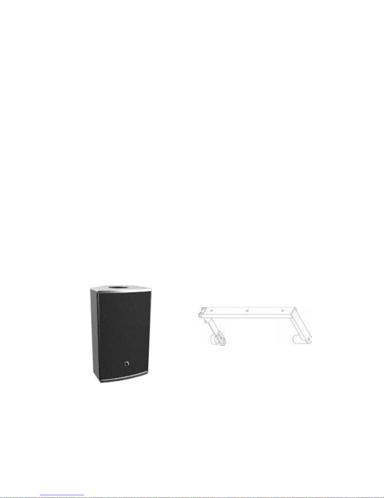
(1) MTD108a
Passive 2-way coaxial loudspeaker, containing 8” loudspeaker, 1” exit high frequency
compression driver with 100 degree axi-symmetrical coverage.
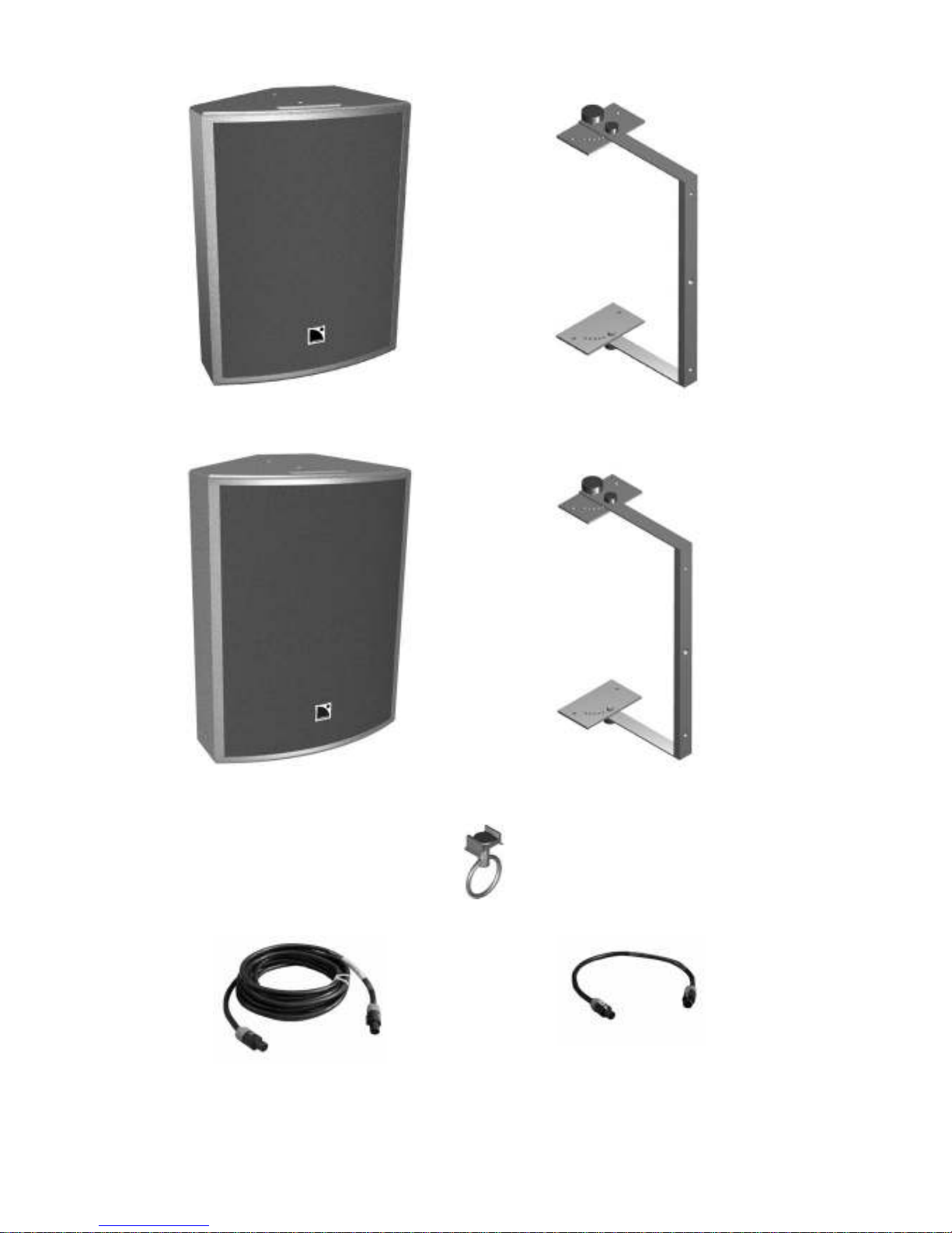
(2) MTD112b
Passive 2-way coaxial loudspeaker, containing 12” loudspeaker, 1.4” exit high frequency
compression driver with 85 degree axi-symmetrical coverage.
(3) MTD115b
Switchable active/passive 2-way coaxial loudspeaker, containing 15” loudspeaker, 1.4” exit high
frequency compression driver with 85 degree axi-symmetrical coverage.
SUBWOOFER ENCLOSURES
(4) SB115
Front-loaded, bass-reflex design, single 15’’ subwoofer for low frequency extension
(5) SB118
Dual bandpass-loaded, single 18’’ subwoofer for high level, extended bandwidth applications.
(6) SB218
Front-loaded, bass-reflex design, dual 18’’ subwoofer for high level, extended bandwidth
applications.
For more information concerning SB115, SB118 and SB218 subwoofer enclosures please consult the SB
Subwoofer User’s Manual
L-ACOUSTICS MTD Manual V1.2 11/30/2004 8
LINE LEVEL CONTROLLERS
(7) MTD108 LLCa
Stereo analog line level controller for use with the MTD108a
(8) LLC112b-st
Stereo analog line level controller for use with the MTD112b
(9) LLC115b-st
Stereo analog line level controller for use with the MTD115b in passive mode
(10) LLC115b-2w
Mono analog line level controller for use with the MTD115b in 2-way active mode
MTD RIGGING ACCESSORIES
(11) ETR 8 : Adjustable U-Bracket for ceiling, wall or scaffold mounting of the MTD108a in
either horizontal or vertical orientations
(11) ETR 1 : Adjustable U-Bracket for ceiling, wall or scaffold mounting of the MTD112b (vertical
orientation only)
(11) ETR 2 : Adjustable U-Bracket for ceiling, wall or scaffold mounting of the MTD115b or
SB115subwoofer (vertical orientation only)
(12) PION 1 : Single stud Aeroquip flytrack fitting-to-ring for use as a safety attachment in
conjunction with MTD112b and ETR1, or MTD115b and ETR2
LOUDSPEAKER CABLES
(12) F-CABLE (SP7, SP25)
Loudspeaker cable, 4 conductor, 4mm
2
conductor cross-section, 7 m (20 ft) or 25 m (80 ft)
length, equipped with 2 x Speakon connectors
(13) F-LINK CABLE (SP.7)
Loudspeaker link cable, 4 conductor, 4mm
2
conductor cross-section, 0.7 m (2 ft) length,
equipped with 2 x Speakon connectors (for paralleling MTD enclosures).
MTD108a
ETR8
L-ACOUSTICS MTD Manual V1.2 11/30/2004 9
MTD112b
ETR1
MTD115b
ETR2 (for MTD115b or SB115)
PION1
F-CABLE DO7
F-LINK CABLE DO.7
Figure 1: MTD System Components
L-ACOUSTICS MTD Manual V1.2 11/30/2004 10
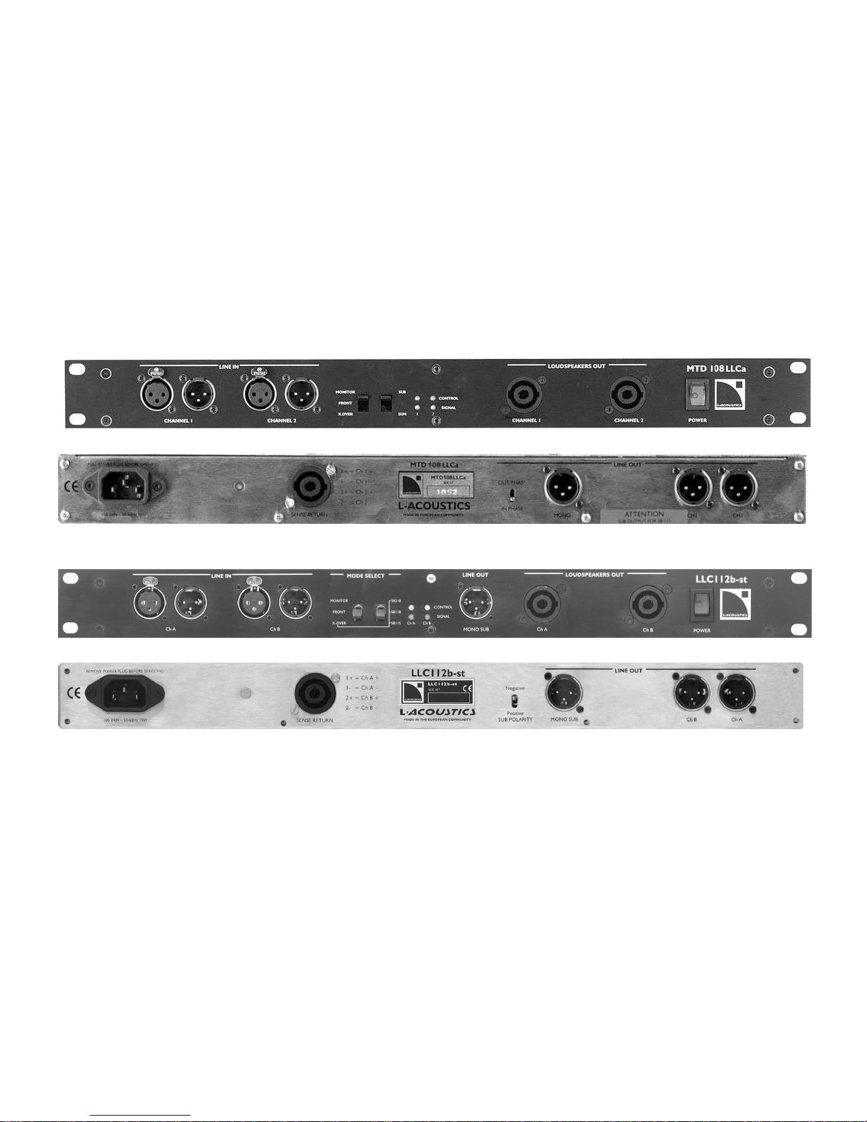
MTD108 LLCa (front)
MTD108 LLCa (rear)
LLC112b-st (front)
LLC112b-st (rear)
L-ACOUSTICS MTD Manual V1.2 11/30/2004 11
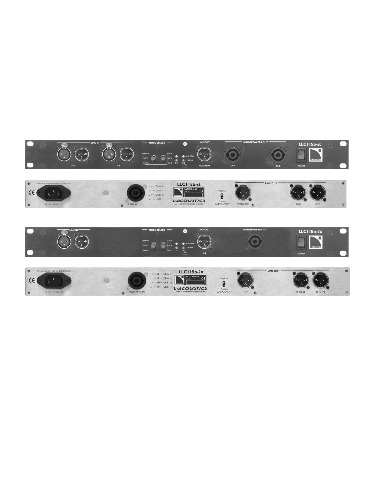
LLC115b-st (front)
LLC115b-st (rear)
LLC115b-2w (front)
LLC115b-2w (rear)
Figure 2: MTD LLC Controllers

L-ACOUSTICS MTD Manual V1.2 11/30/2004 12
1.2 MTD OVERVIEW
L-ACOUSTICS MTD108a, MTD112b and MTD115b loudspeaker enclosures along with their
respective analog controllers provide highly versatile, multi-purpose systems that are designed for
distributed sound reinforcement. Intended for medium-scale touring, sub-hire or fixed installation, the
MTD line of enclosures benefit from the economy, packaging and “plug and play” ease of use afforded
by their companion LLC analog line level controllers.
The MTD108a is a passive 2-way loudspeaker containing a 1” neodymium compression driver that is
directly loaded by the 8” loudspeaker in a coaxial configuration. The MTD112b is a passive 2-way
loudspeaker containing a 1.4" exit compression driver and 12" loudspeaker in a coaxial configuration
while the MTD115b is switchable active/passive and features a 15” loudspeaker plus 1.4" exit
compression driver. As discussed in the introduction, advantages of the coaxial approach include:
single point source radiation and excellent phase response, total wavefront coherency at all
frequencies and axi-symmetrical directivity that produces identical horizontal and vertical coverage.
Coaxial design also provides LF/HF superimposed dispersion characteristics that are free of polar
lobing effects typical of traditional horn and woofer combinations. The end result is natural, studio
monitor level sound quality, ideal for proximity use and perfectly matching semi-reverberant
environments.
The MTD108a, MTD112b or MTD115b are ideal for distributed sound reinforcement and can also be
used in medium power front-of-house (FOH) applications for theatres, clubs, multi-purpose venues or
corporate events. Examples of distributed systems include delay rings for large-scale installations,
surround effects channels for theatre or multimedia, distributed reinforcement for sports venues, and
delays for speech reinforcement in convention centre ballrooms. Due to their compact, wedgeshaped format, axi-symmetrical directivity and full range passive design, MTD enclosures also provide
a cost-effective, high performance floor monitor solution for live sound reinforcement. When used
with additional subwoofers such as the SB115, SB118 or SB218, the MTD line of enclosures can also
be used for side fill or drum monitoring applications.
The L-ACOUSTICS MTD108LLCa, LLC112b-st, LLC115b-st and LLC115b-2w are dedicated analog
controllers that provide optimum signal processing and protection for the MTD108a, MTD112b,
MTD115b (passive mode) and MTD115b (active mode), respectively. Active sense return monitoring
guarantees safe system operation with LLC controllers providing both thermal protection and cone
excursion limiting. LLC controllers also generate a subwoofer feed with switchable high pass filtering
and equalization for use with SB115, SB118 or SB218 subwoofers. Front panel design also allows LLC
controllers to function as a patch panel, providing an ergonomic, cost-effective solution for amplifier
rack packaging.
Pole mount sockets are included as standard and all MTD enclosures are Omnimount-ready.
Adjustable U-brackets are available as optional rigging accessories, allowing MTD enclosures to be
ceiling-, wall- or scaffold-mounted. As standard on the MTD112b and MTD115b, single stud anchor
plates are included for installation of a safety steel using the optional PION1 (single stud Aeroquip
flytrack fitting-to-ring) accessory.
L-ACOUSTICS MTD Manual V1.2 11/30/2004 13
1.3 MTD108a SPECIFICATIONS
The MTD108a is a passive 2-way coaxial full range loudspeaker containing one 8-inch, direct radiating
low frequency component and one 1-inch titanium diaphragm, neodymium magnet, compression
driver. As a full range system, the frequency response is 85 - 20k Hz with less than ± 3 dB variation
and the usable bandwidth is 65 – 20k Hz (-10 dB). Sonic quality and the ratio of performance-to-size
were the chief design criteria for the MTD108a and its frequency response is exceptionally flat,
providing excellent fidelity and optimum speech intelligibility.
The MTD108a is ideal for distributed sound reinforcement in theatre, corporate, restaurant, retail,
club, or television (A/V) applications and is an excellent candidate for delay ring, front fill or under
balcony use. The ultra-compact format of the MTD108a allows for visually discrete installation in all of
these applications. The MTD108a is equally useful as a compact, high-efficiency floor monitor for
concert, theatre, dance, corporate or television applications. Given its superb fidelity and dynamic
response, the MTD108a is effective in situations that are typically unaccustomed to sound
reinforcement, in particular, for classical music and opera where high quality sound reinforcement is
essential.
The cone body of the 8” low frequency component provides pattern control loading of the
compression driver and yields a 100-degree (±15 degrees) conical directivity that is vertically,
horizontally and diagonally symmetrical (i.e., axi-symmetric). As implemented in the passive crossover
network, the crossover point between low and high sections is 2 kHz. Long term power handling
capacity is 250 Wrms at a nominal 8 ohm impedance and connection to the loudspeaker is made via
two parallel 4-pin Neutrik Speakon connectors.
For floor monitoring, the MTD108a has either 22.5° or 45° listening angles with respect to vertical for
short throw or long throw applications, respectively. Dimensions are 42.1 cm (16.6 in) high, 25.0 cm
(9.8 in) wide by 24.2 cm (9.5 in) deep and the weight is 10.5 kg (23.1 lbs). Cabinet construction
consists of 15 mm (0.6 in) and 18 mm (0.7 in) Baltic birch plywood with joints that are sealed,
screwed and rabbeted. The finish is maroon gray, high resiliency paint and the front of the
loudspeaker is protected by a black powder-coated 1.5 mm (0.06 in) thick steel grill that is covered
with 5 mm (0.2 in) thick acoustically transparent open cell foam.
The MTD108a has 4 integral rear attachment points for wall mounting using an optional Omnimount
rigging accessory along with a 36 mm (1.42 in) diameter pole mount socket for tripod mounting. An
integral top plate and the bottom pole mount socket also allows for rigging the MTD108a using the
optional ETR8 adjustable U bracket.
The L-ACOUSTICS MTD108LLCa is a stereo analog controller that provides optimum equalization
and band limiting for the MTD108a along with system protection and processing for use with
subwoofers. Active sense return monitoring guarantees safe operation and the controller provides
both thermal protection and cone excursion limiting.
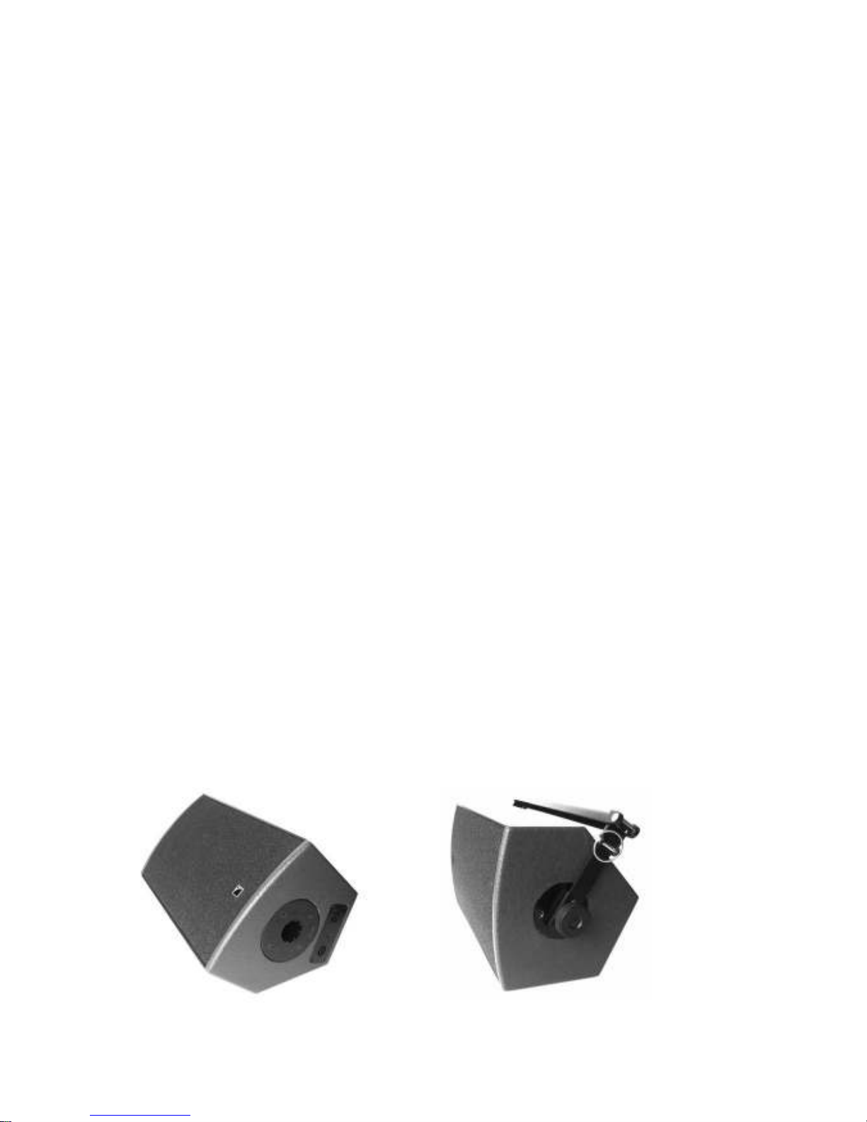
Figure 3: MTD108a passive 2-way (8” LF + 1” HF) coaxial loudspeaker
L-ACOUSTICS MTD Manual V1.2 11/30/2004 14
1.4 MTD112b SPECIFICATIONS
The MTD112b is a passive, two-way, coaxial full range loudspeaker containing one direct radiating,
bass reflex-loaded 12 inch low frequency transducer and one 1.4 inch exit, 3 inch voice coil diameter,
titanium alloy diaphragm compression driver. As a full range system, the frequency response is 70 Hz
to 14 kHz with less than ± 3 dB variation and the usable bandwidth is 55 Hz to 16 kHz (-10 dB).
The cone body of the low frequency component provides pattern control loading of the compression
driver, yielding an 85-degree (± 20-degree) conical dispersion pattern that is axi-symmetrical. The 2
nd
and 3
rd
order passive filters employed in the MTD112b provide a 1.2 kHz crossover point between
low and high frequency components. Long term power handling is 450 Wrms at a nominal 8 ohm
impedance and connection to the loudspeaker is made via two parallel 4-pin Neutrik Speakon
connectors.
The MTD112b has a truncated wedge shape with a curved front profile. When used on its rear side,
the front baffle of the enclosure is oriented at a 45 degree angle with respect to vertical, allowing the
enclosure to be used as a floor monitor.
Dimensions are 54 cm (21.3 in) high, 41 cm (16.1 in) wide at the front of the enclosure, 16.5 cm (6.5
in) wide at the rear of the enclosure and 37.5 cm (14.8 in) deep. Enclosure weight is 26.5 kg (58.4 lbs)
and cabinet construction consists of 18 mm (0.70 in) and 30 mm (1.18 in) Baltic birch plywood with
internal steel bracing and joints that are sealed, screwed and rabbeted. The finish is maroon-gray high
resilient paint and the front of the enclosure is protected by a black powder-coated, 1.5 mm (0.06 in)
thick steel grill that is covered with 10 mm (0.4 in) thick acoustically transparent open cell foam.
The MTD112b has a 36 mm (1.42 in) diameter pole mount socket mounted on the bottom side and a
single stud anchor plate mounted on the rear side along with four threaded inserts for attachment of
an optional Omnimount bracket. Four recessed attachment locations are available (two on each top
and bottom side) for rigging the enclosure with the optional ETR1 adjustable U-bracket accessory.
The MTD112b is used with the LLC112b-st stereo analog controller that monitors power amplifier
outputs and employs sense return processing to provide thermal protection and cone excursion
limiting for the loudspeaker components. The analog controller provides band limiting and corrective
component equalization with three settings that are designed for front-of-house, floor monitor or
two-way operation with subwoofers. The LLC112b-st controller also performs signal summation of
the two input signal channels and provides a line level output signal with selectable band limiting and
equalization for use of the MTD112b in conjunction with SB115, SB118 or SB218 subwoofers.
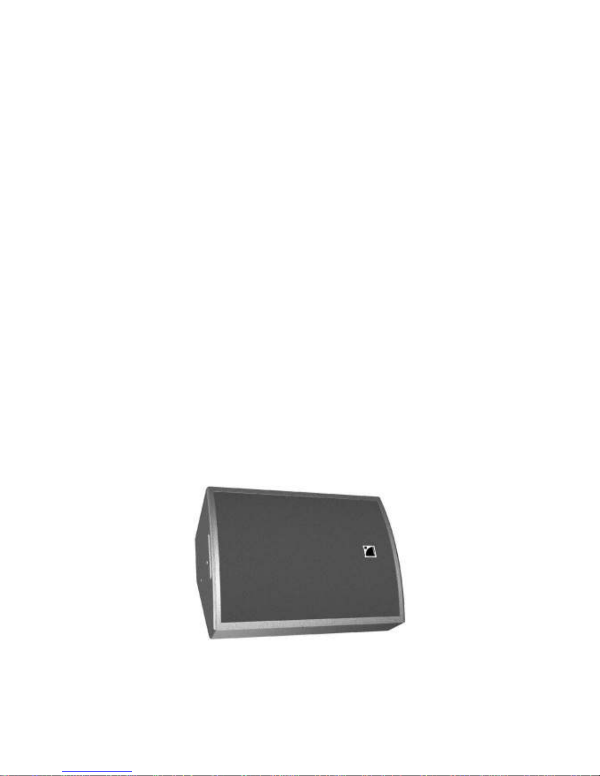
Figure 4: MTD112b passive 2-way (12” LF + 1.4” HF) coaxial loudspeaker
L-ACOUSTICS MTD Manual V1.2 11/30/2004 15
1.5 MTD115b SPECIFICATIONS
The MTD115b is a switch-selectable active/passive, two-way, coaxial full range loudspeaker containing
one direct radiating, bass reflex-loaded 15 inch low frequency transducer and one 1.4 inch exit, 3 inch
voice coil diameter, titanium alloy diaphragm compression driver. As a full range system, the
frequency response is 65 Hz to 14 kHz with less than ± 3 dB variation and the usable bandwidth is 50
Hz to 16 kHz (-10 dB).
The cone body of the low frequency driver provides pattern control loading of the compression
driver, yielding an 85-degree (± 20-degree) conical dispersion pattern that is axi-symmetrical. The 2
nd
and 3
rd
order passive filters employed in the MTD115b provide a 1.2 kHz crossover point between
low and high frequency components. In passive mode, long term power handling is 265 Wrms at a
nominal 8 ohm impedance. In active mode, the crossover point between low and high frequency
components is 1.2 kHz with 24 dB per octave Linkwitz-Riley characteristics and long term power
handling is 265 Wrms for the low section and 150 Wrms for the high section at a nominal 8 ohm
impedance. Connection to the loudspeaker is made via two parallel 4-pin Neutrik Speakon
connectors.
The MTD115b has a truncated wedge shape with a curved front profile. When used on its rear side,
the front baffle of the MTD115b is oriented at a 41 degree angle with respect to vertical, allowing the
enclosure to be used as a floor monitor.
Dimensions are 58 cm (22.8 in) high, 44 cm (17.3 in) wide at the front of the enclosure, 16.7 cm (6.6
in) wide at the rear and 47.5 cm (18.7 in) deep. Enclosure weight is 32.5 kg (71.6 lbs) and cabinet
construction consists of 18 mm (0.70 in) and 30 mm (1.18 in) Baltic birch plywood with internal steel
bracing and joints that are sealed, screwed and rabbeted. The finish is maroon-gray high resilient paint
and the front of the enclosure is protected by a black powder-coated, 1.5 mm (0.06 in) thick steel grill
that is covered with 10 mm (0.39 in) thick acoustically transparent open cell foam.
The MTD115b has a 36 mm (1.42 in) diameter pole mount socket mounted on the bottom side and a
single stud anchor plate mounted on the rear side along with four threaded inserts for attachment of
an optional Omnimount bracket. Four recessed attachment locations are provided (two on each top
and bottom side) for rigging the enclosure with the optional ETR2 adjustable U-bracket accessory.
When operated in passive mode, the MTD115b is used with the LLC115b-st stereo analog controller,
and in active mode, the LLC115b-2w mono two-way analog controller is specified. Both analog
controllers monitor power amplifier outputs and employ sense return processing to provide thermal
protection and cone excursion limiting for the loudspeaker components. Analog controllers also
provide band limiting and corrective component equalization with three settings that are designed for
front-of-house, floor monitor or two-way operation with subwoofers. The LLC115b-st stereo
controller performs signal summation of the two input signal channels and both controllers provide a
line level output signal with selectable band limiting and equalization for use of the MTD115b in
conjunction with SB115, SB118 or SB218 subwoofers.
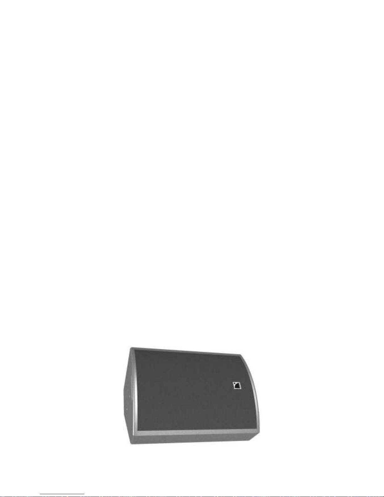
Figure 5: MTD115b active/passive 2-way (15” LF + 1.4” HF) coaxial loudspeaker
L-ACOUSTICS MTD Manual V1.2 11/30/2004 16
2. POWERING MTD
It is important that power amplifiers with sufficient power are used to power MTD108a, MTD112b or
MTD115b loudspeakers since headroom is less likely to damage loudspeaker components than
clipping. Apart from normal standards regarding construction, protection, cooling and damping factor
that are expected of any professional sound reinforcement amplifier, MTD loudspeakers and LLC
controllers are intended to be used with amplifiers with the following specifications:
GAIN STRUCTURE
Protection circuitry employed in all LLC Controllers is calibrated and optimized for 32 dB amplifier gain.
LLC controllers can be safely used with amplifiers having less than 32 dB gain, however, the maximum
SPL output obtainable from your loudspeaker system will be less than optimum. In addition, due to
the higher input sensitivity of lower gain amplifiers (i.e., less input signal level is required in order to
drive the amplifier to clip) it is also possible that LLC controller limiting circuitry will not operate
correctly. This could allow amplifiers to be operated under continuous clipping conditions and may
result in damage to your loudspeaker.
For amplifiers with more than 32 dB gain, in extreme cases, oscillation of LLC controller sense return
circuitry can occur, resulting in potential damage to the MTD loudspeaker and/or amplifier. For
amplifiers with greater than 32 dB gain, please contact your amplifier supplier for technical support
regarding how to calibrate the amplifier for 32 dB gain.
LIMITERS
Peak limiters on all amplifier outputs with soft clipping characteristics; attack time less than 3msec
COOLING
Temperature speed-controlled fan recommended
In practice, L-ACOUSTICS specifies power amplifiers with output power equivalent to twice the RMS
power handling for the low section and equivalent to the peak power handling for the high section.
These requirements typically allow the same amplifier to be used for both sections since the drive
level for the HF section is attenuated relative to the LF section to account for efficiency differences
(i.e., full continuous power will never be delivered to the HF section due to this attenuation). When
the same amplifier is used for the HF section, the extra available power then translates into headroom
for improved high frequency transient response.
Sections 2.1, 2.2, 2.3 and 2.4 give a summary of rms and peak power handling along with
recommended power amplifier output specifications for operation of single or multiple MTD108a,
MTD112b or MTD115b (active or passive mode) enclosures.
As standard, L-ACOUSTICS LA power amplifiers are 32 dB gain and there are four models available:
LA15a, LA17a, LA24a and LA48a (please see Table 11 for a specification summary). L-ACOUSTICS LA
amplifiers can be configured to provide power matching into different loads (for example, Figure 6
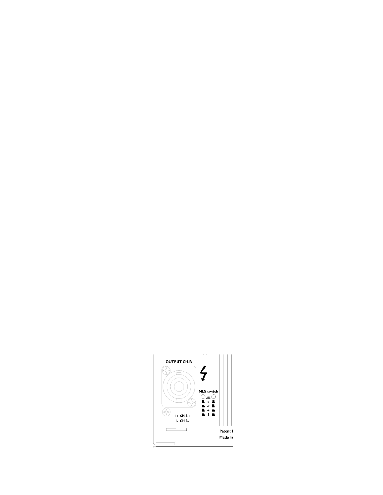
shows the location of MLS switches on the LA24a and LA48a rear panel).
Figure 6: MLS switches on the rear panel of L-ACOUSTICS LA24a, LA48a amplifiers

L-ACOUSTICS MTD Manual V1.2 11/30/2004 17
2.1 POWERING MTD108a
Continuous (rms) and peak power handling ratings for the MTD108a are as follows:
45 volts rms long term (pink noise with 6 dB crest factor)
250 Watts (continuous), 1000 Watts (peak) at 8 ohms
Recommended power amplifier specification for powering single and multiple MTD108a enclosures
are given in Table 1.
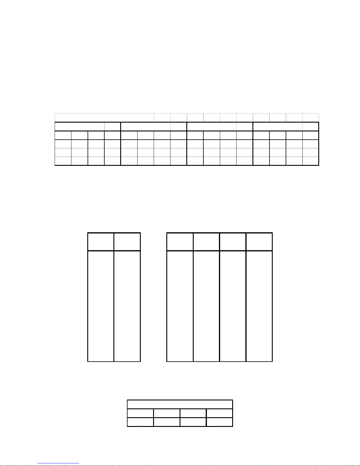
Table 1: Load and Power Ratings for MTD108a
MTD108a EN CLO SURE RATING S
ONE MTD108a TWO MTD108a THREE MTD108a FOUR MTD108a
LOAD RMS PEAK REC'D LOAD RMS PEAK REC'D LOAD RMS PEAK REC'D LOAD RMS PEAK REC'D
8 250 1000
500
4 500 2000
1000
2.7 750 3000
1500
2 1000 4000
2000
Based on these specifications, recommended L-ACOUSTICS LA power amplifier specifications and
MLS switch settings are summarized in Table 2. Boldface settings indicate a good power match based
on the recommended power amplifier specification.
Table 2: Recommended power amplification and MLS switch settings for MTD108a
RECOMMENDED AMPLIFIER OUTPUT POWER
POWER AMP (MLS SETTING)
LOAD POWER LA15a LA 17a LA 24a LA 48a
(ohms) (W)
2 2000 do not use 1200 1700
2000
(0 dB) (0 dB)
(-4 dB)
2.7 1500 do not use 1080
1465 1665
(0 dB)
(-2 dB) (-4 dB)
4 1000 600
840 1300 1000
(0 dB)
(0 dB) (-2 dB) (-4 dB)
8 500 370
430 700 520
(0 dB)
(0 dB) (-2 dB) (-4 dB)
L-ACOUSTICS LA amplifier MLS switch settings for powering the MTD108a are summarized in Table
4 and Figure 6 shows the location of MLS switches on the LA24a and LA48a rear panel.
Table 3: Recommended MLS switch settings for powering MTD108a
MTD108a MLS SWITCH SETTING
LA15a LA17a LA24a LA48a
0 dB 0 dB -2 dB -4 dB
L-ACOUSTICS MTD Manual V1.2 11/30/2004 18
2.2 POWERING MTD112b
Continuous (rms) and peak power handling ratings for the MTD112b are as follows:
45 volts rms long term (pink noise with 6 dB crest factor)
250 Watts (continuous), 1000 Watts (peak) at 8 ohms
Recommended power amplifier specification for powering single and multiple MTD112b enclosures
are given in Table 4.
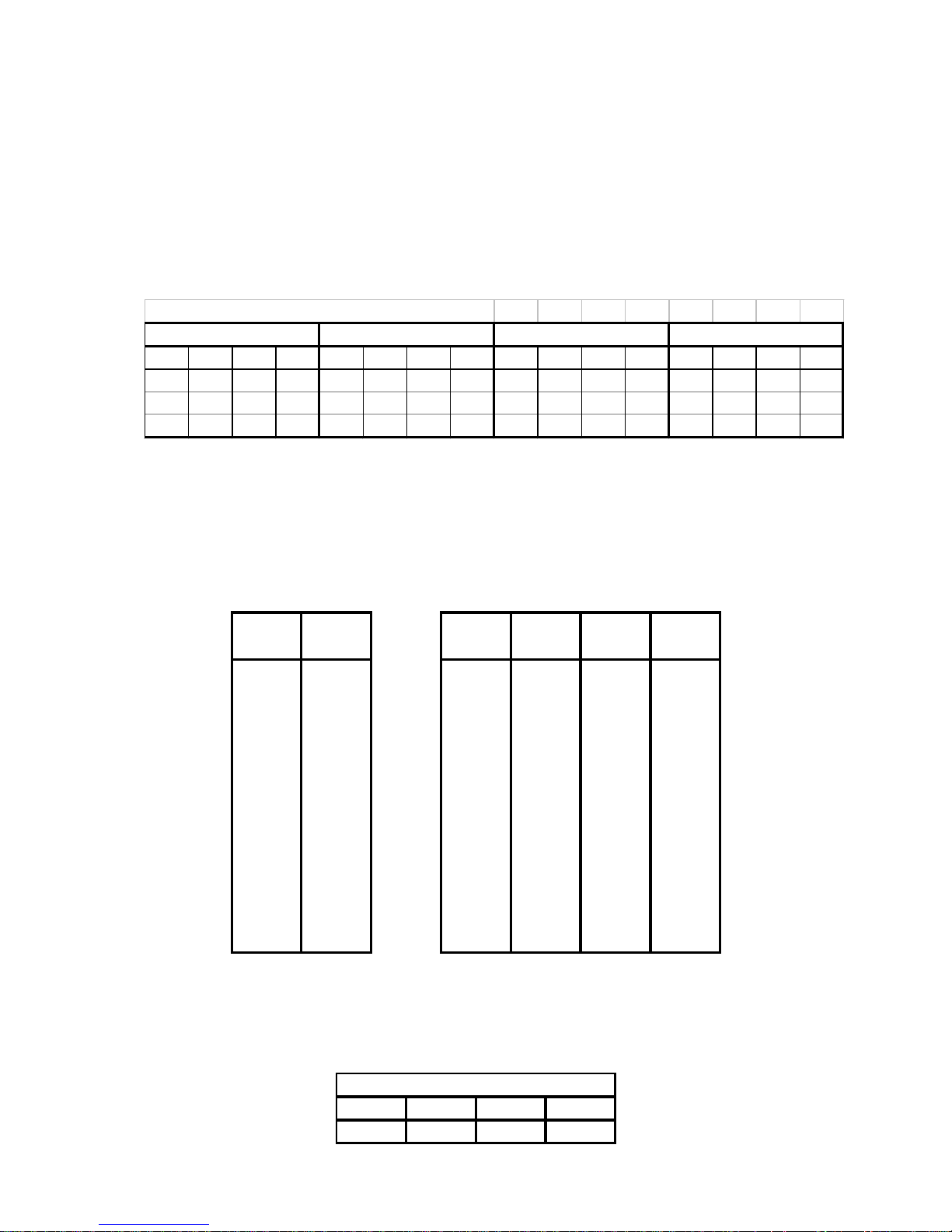
Table 4: Load and Power Ratings for MTD112b
MTD112b ENCLOSURE RATINGS
ONE MTD112b TWO MTD112b THREE MTD112b FOUR MTD112b
LOAD RMS PEAK REC'D LOAD RMS PEAK REC'D LOAD RMS PEAK REC'D LOAD RMS PEAK REC'D
8 250 1000
500
4 500 2000
1000
2.7 750 3000
1500
2 1000 4000
2000
Based on these specifications, recommended L-ACOUSTICS LA power amplifier specifications and
MLS switch settings are summarized in Table 5. Boldface settings indicate a good power match based
on the recommended power amplifier specification.
Table 5: Recommended power amplification and MLS switch settings for MTD112b
RECOMMENDED AMPLIFIER OUTPUT POWER
POWER AMP (MLS SETTING)
LOAD POWER LA15a LA 17a LA 24a LA 48a
(ohms) (W)
2 2000 do not use 1200 1700
2000
(0 dB) (0 dB)
(-4 dB)
2.7 1500 do not use 1080
1465 1665
(0 dB)
(-2 dB) (-4 dB)
4 1000 600
840 1300 1000
(0 dB)
(0 dB) (-2 dB) (-4 dB)
8 500 370
430 700 520
(0 dB)
(0 dB) (-2 dB) (-4 dB)
L-ACOUSTICS LA amplifier MLS switch settings for powering the MTD112b are summarized in Table
6 and Figure 6 shows the location of MLS switches on the LA24a and LA48a rear panel.
Table 6: Recommended MLS switch settings for powering MTD112b
MTD112b MLS SWITCH SETTING
LA15a LA17a LA24a LA48a
0 dB 0 dB -2 dB -4 dB
L-ACOUSTICS MTD Manual V1.2 11/30/2004 19
2.3 POWERING MTD115b (PASSIVE MODE)
Continuous (rms) and peak power handling ratings for the MTD11b (passive mode) are as follows:
46 volts rms long term (pink noise with 6 dB crest factor)
265 Watts (continuous), 1060 Watts (peak) at 8 ohms
Recommended power amplifier specification for powering single and multiple MTD115b enclosures in
passive mode are given in Table 7.
Table 7: Load and Power Ratings for MTD115b (passive mode)
MTD115b (PASSIVE MO DE) ENCLOSURE RATINGS
ONE MTD115b (PASSIVE) TWO MTD115b (PASSIVE) THREE MTD115b (PASSIVE) FOUR MTD115b (PASSIVE)
LOAD RMS PEAK REC'D LOAD RMS PEAK REC'D LOAD RMS PEAK REC'D LOAD RMS PEAK REC'D
8 265 1060
530
4 530 2120
1060
2.7 795 3180
1590
2 1060 4240
2120
Based on these specifications, recommended L-ACOUSTICS LA power amplifier specifications and
MLS switch settings are summarized in Table 8. Boldface settings indicate a good power match based
on the recommended power amplifier specification.
Table 8: Recommended power amplification and MLS switch settings for MTD115b (passive mode)
RECOMMENDED AMPLIFIER OUTPUT POWER
POWER AMP (MLS SETTING)
LOAD POWER LA15a LA 17a LA 24a LA 48a
(ohms) (W)
2 2120 do not use 1200 1700
2000
(0 dB) (0 dB)
(-4 dB)
2.7 1590 do not use 1080
1635 1665
(0 dB)
(0 dB) (-4 dB)
4 1060 600
840 1300 1000
(0 dB)
(0 dB) (-2 dB) (-4 dB)
8 530 370
430 700 520
(0 dB)
(0 dB) (-2 dB) (-4 dB)
L-ACOUSTICS LA amplifier MLS switch settings for powering the MTD115b in passive mode are
summarized in Table 9 and Figure 6 shows the location of MLS switches on the LA24a and LA48a rear
panel.
Table 9: Recommended MLS switch settings for powering MTD115b (passive mode)
MTD115b (PASSIVE) MLS SETTING
LA15a LA17a LA24a LA48a
0 dB 0 dB -2 dB -4 dB
L-ACOUSTICS MTD Manual V1.2 11/30/2004 20
2.4 POWERING MTD115b (ACTIVE MODE)
Continuous (rms) and peak power handling ratings for the MTD115b in active mode are as follows:
LF Section: 46 volts rms long term (pink noise with 6 dB crest factor)
265 Watts (continuous), 1060 Watts (peak) at 8 ohms
HF Section: 35 volts rms long term (pink noise with 6 dB crest factor)
150 Watts (continuous), 600 Watts (peak) at 8 ohms
Recommended power amplifier specification for powering single and multiple MTD115b enclosures in
active mode are given in Table 10.
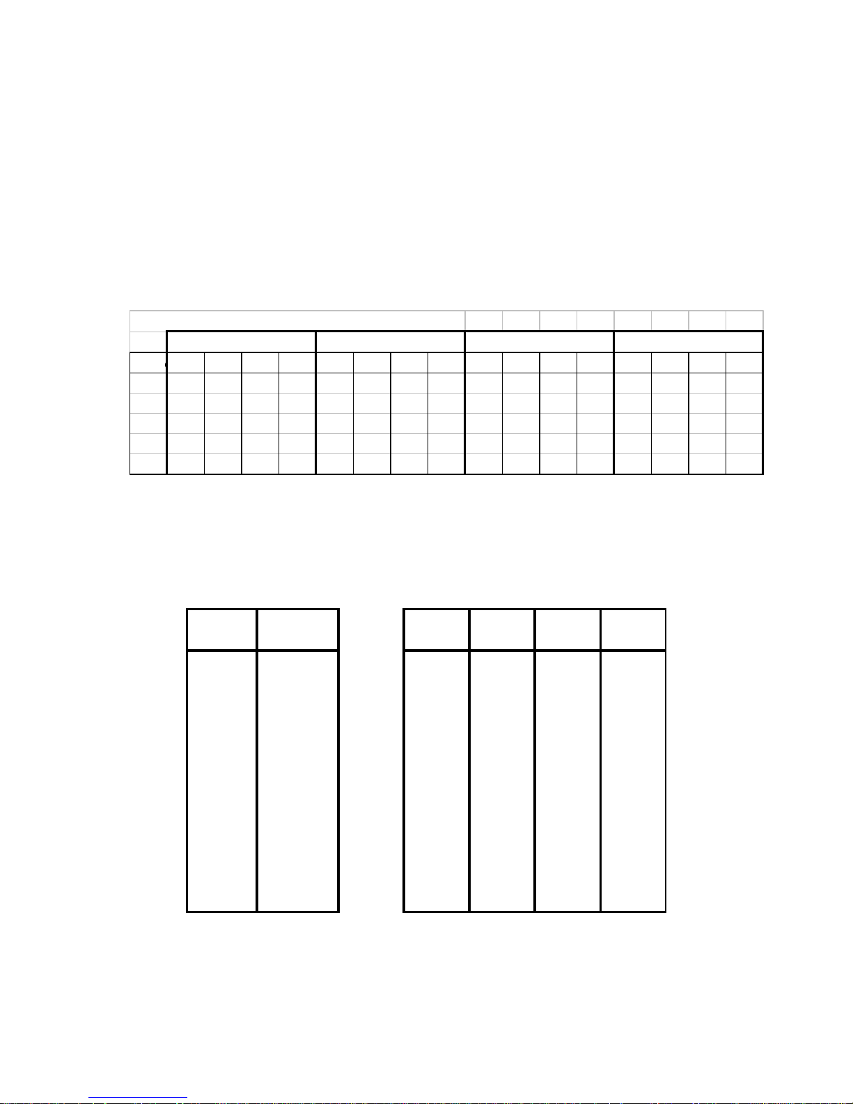
Table 10: Load and Power Ratings for MTD115b (active mode)
MTD115b (ACTIVE MODE) ENCLOSURE RATINGS
ONE MTD115b (ACTIVE) TWO MTD115b (ACTIVE) THREE MTD115b (ACTIVE FOUR MTD115b (ACTIVE)
SECTIOLOAD RMS PEAK REC'D LOAD RMS PEAK REC'D LOAD RMS PEAK REC'D LOAD RMS PEAK REC'D
LOW 8 265 1060
530
4 530 2120
1060
2.7 795 3180
1590
2 1060 4240
2120
HIGH 8 150 600
600
4 300 1200
1200
2.7 440 1760
1760
2 600 2400
2400
Based on these specifications, recommended L-ACOUSTICS LA power amplifier specifications and
MLS switch settings are summarized below in Tables 11 and 12.
Table 11: Recommended power amplification and MLS switch settings for MTD115b low section
MTD115b LOW SECTION AMPLIFIER OUTPUT POWER
REC'D POWER (MLS SETTING)
LOAD POWER LA15a LA 17a LA 24a LA 48a
(ohms) (W)
2 2120 do not use 1200 1700
2400
(0 dB) (0 dB)
(-2 dB)
2.7 1590 do not use 1080
1635 1665
(0 dB)
(0 dB) (-4 dB)
4 1060 600
840 1300 1000
(0 dB)
(0 dB)(-2 dB)(-4 dB)
8 530 370
430 700 520
(0 dB)
(0 dB)(-2 dB)(-4 dB)
 Loading...