

L-Acoustics LA-RAK II User Manual
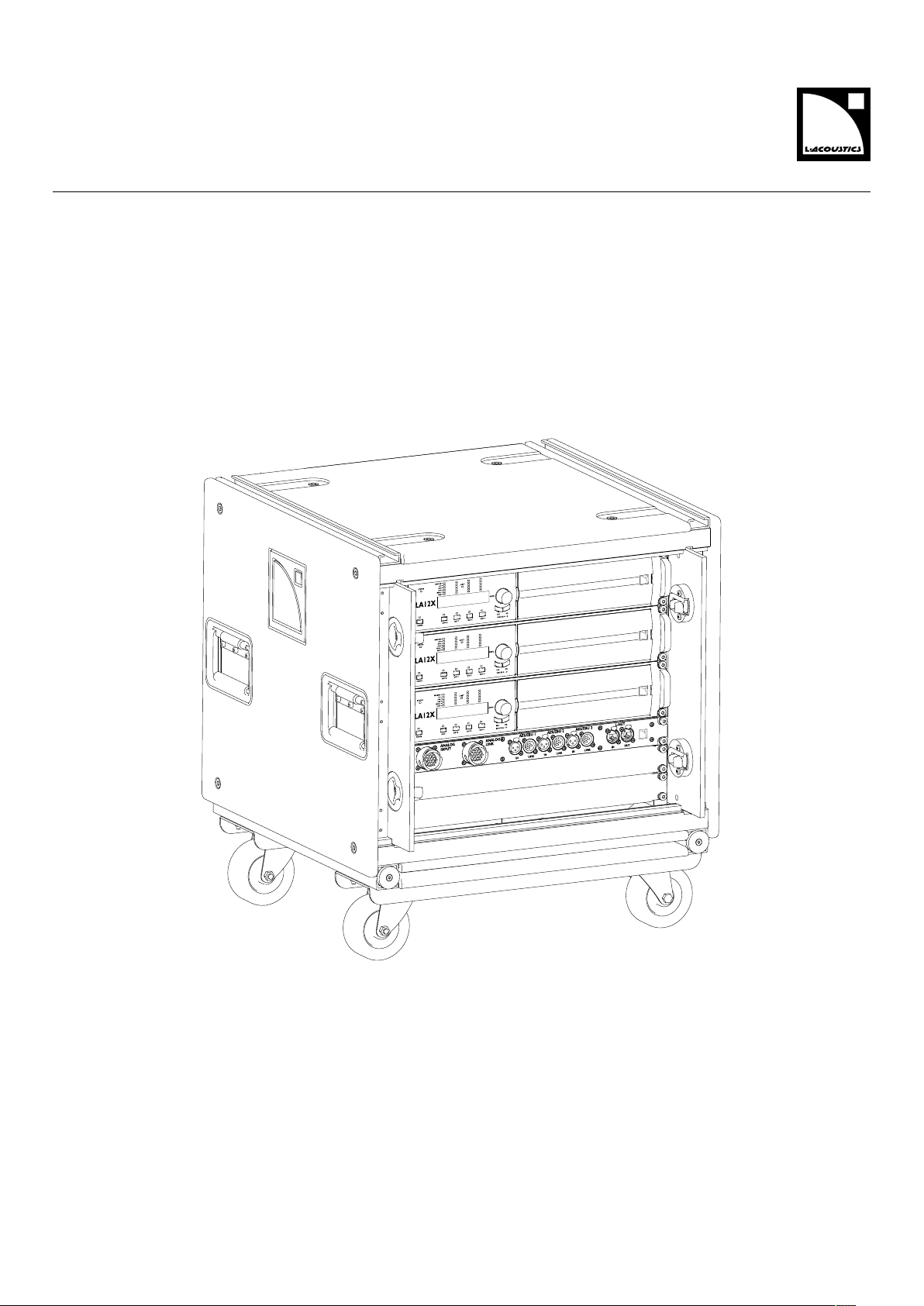
LA-RAK II
user manual (EN)

Document reference: LA-RAK II user manual (EN) version 2.0
Distribution date: March 24, 2017
©
2017 L-Acoustics. All rights reserved.
No part of this publication may be reproduced or transmitted in any
form or by any means without the express written consent of the
publisher.

Contents
Safety................................................................................................................................................................ 5
Important safety instructions....................................................................................................................... 5
Additional important safety instructions....................................................................................................... 6
Symbols................................................................................................................................................... 7
System components............................................................................................................................................. 9
Technical description......................................................................................................................................... 10
Main features......................................................................................................................................... 10
RK9U structure.............................................................................................................................. 10
LA12X amplied controller............................................................................................................. 11
LA-POWERII distribution panel.......................................................................................................12
LA-PANELII distribution panel......................................................................................................... 13
Installation........................................................................................................................................................14
Transporting........................................................................................................................................... 14
Ventilation.............................................................................................................................................. 14
Connecting to AC mains......................................................................................................................... 16
EU mode......................................................................................................................................16
US mode......................................................................................................................................17
Powering the amplied controllers.................................................................................................. 18
Analog audio cabling............................................................................................................................. 19
Internal analog audio cabling........................................................................................................ 19
External analog audio cabling....................................................................................................... 21
Digital audio cabling.............................................................................................................................. 22
Internal digital audio cabling......................................................................................................... 22
External digital audio cabling........................................................................................................ 24
Loudspeaker cabling............................................................................................................................... 26
L-NET cabling......................................................................................................................................... 27
Internal L-NET cabling....................................................................................................................27
External L-NET cabling...................................................................................................................28
Maintenance.................................................................................................................................................... 31
Quality control........................................................................................................................................31
INSP - Structure.............................................................................................................................31
CHK - Internal components.............................................................................................................31
Mounting components on the RK9U inner frame........................................................................................ 32
Specications................................................................................................................................................... 35
LA-RAKII specications............................................................................................................................35
3

LA-PANEL II specications........................................................................................................................ 36
LA-POWERII specications...................................................................................................................... 37
Approvals........................................................................................................................................................ 38
4
Safety
Important safety instructions
Safety
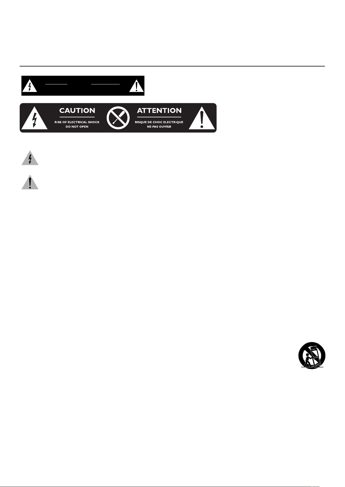
CAUTION
RISK OF ELECTRIC SHOCK
DO NOT OPEN
ATTENTION
RISQUE DE CHOC ELECTRIQUE
NE PAS OUVRIR
Explanation of graphical symbols
The lightning ash with arrowhead symbol within an equilateral triangle is intended to alert the user
to the presence of uninsulated "dangerous voltage" within the product's enclosure that may be of
sufcient magnitude to constitute a risk of electric shock to persons.
The exclamation point within an equilateral triangle is intended to alert the user to the presence of
important operating and maintenance instructions in the literature accompanying the product.
1. Read these instructions.
2. Keep these instructions.
3. Heed all warnings.
4. Follow all instructions.
5. Do not use this apparatus near water.
6. Clean only with dry cloth.
7. Do not block any ventilation openings. Install in accordance with the manufacturer's instructions.
8. Do not install near any heat sources such as radiators, heat registers, stoves, or other apparatus
(including ampliers) that produce heat.
9. Do not defeat the safety purpose of the grounding-type plug. A grounding-type plug has two blades
and a third grounding prong. The third prong is provided for your safety. If the provided plug does not
t into your outlet, consult an electrician for replacement of the obsolete outlet.
10. Protect the power cord from being walked on or pinched particularly at plugs, convenience
receptacles, and the point where they exit from the apparatus.
11. Only use attachments/accessories specied by the manufacturer.
12. Use only with the cart, stand, tripod, bracket, or table specied by the manufacturer, or sold with the
apparatus. When a cart is used, use caution when moving the cart/apparatus combination to avoid
injury from tip-over.
13. Unplug this apparatus during lightning storms or when unused for long periods of time.
14. Refer all servicing to qualied service personnel. Servicing is required when the apparatus has been
damaged in any way, such as power-supply cord or plug is damaged, liquid has been spilled or
objects have fallen into the apparatus, the apparatus has been exposed to rain or moisture, does not
operate normally, or has been dropped.
15. WARNING: To reduce the risk of re or electric shock, this apparatus should not be exposed to rain or
moisture and objects lled with liquids, such as vases, should not be placed on this apparatus.
16. To completely disconnect this equipment from the mains, disconnect the power supply cord plug from
the receptacle.
Pour déconnecter complètement l'appareil du secteur, débranchez la prise de la che secteur.
5 LA-RAK II user manual (EN) version 2.0
Safety
17. The main plug of the power supply cord shall remain readily accessible.
La prise principale du cordon d'alimentation doit rester totalement accessible.
18. The power supply of the product shall be protected in the installation by a 30 A circuit breaker
certied for constant current at 100% (US MODE 100-120 V).
Additional important safety instructions
Verify the electrical conformity and compatibility of the mains supply.
Only connect the product to an AC power outlet rated 100-240 V, 50-60 Hz, with the following current values:
100-120 V: 30 A (US MODE)
200-240 V: 32 A (EU MODE)
WARNING: The product is of CLASS 1 construction and shall be connected to a mains socket outlet with a
protective connection to earth.
When the product is used in a three-phase circuit, verify the electrical conformity and
compatibility of the three-phase circuit.
Verify that the three phases work, and balance the loads between the three phases.
Verify that the neutral and earth work.
Never try to emulate a 230 V circuit connecting an apparatus to two live wires of a 120 V three-phase circuit.
Never try to emulate a 200 V circuit connecting an apparatus to two live wires of a 100 V three-phase circuit.
Always interconnect a Class C circuit breaker on each phase.
The circuit breaker current rating depends on the mains voltage rating, as follows:
100-120 V: 30 A (US MODE)
200-240 V: 32 A (EU MODE)
Electrical generator
You must power on the generator before powering on the product.
Verify that the product is turned off before powering on the generator.
Terminals marked with the lightning ash symbol are HAZARDOUS LIVE.
The external wiring connected to these terminals requires installation by an instructed person or
the use of ready-made leads or cords.
Never attempt to touch any exposed speaker wiring while the product is operating: rst disconnect the
connector from the product.
Mute all output channels before connecting a speaker to an amplied controller.
Do not connect a speaker output in parallel or series with any output of another amplied controller.
Do not connect the speaker outputs to any other voltage source, such as a battery, power mains, or
power supply, regardless of whether the amplied controller is turned on or off.
Never incorporate equipment or accessories not approved by L-Acoustics.
Read all the related PRODUCT INFORMATION documents shipped with the products before
exploiting the system.
Beware of sound levels.
Do not stay within close proximity of loudspeakers in operation.
Loudspeaker systems are capable of producing very high sound pressure levels (SPL) which can instantaneously
lead to permanent hearing damage to performers, production crew and audience members. Hearing damage
can also occur at moderate level with prolonged exposure to sound.
Check the applicable laws and regulations relating to maximum sound levels and exposure times.
Beware of over power risks.
Only use compatible loudspeakers with appropriate presets to avoid damage to the loudspeakers.
Inspect the product before operation.
If any sign of defect or damage is detected, immediately withdraw the product from use for maintenance.
LA-RAK II user manual (EN) version 2.0 6
This product is intended for use by trained personnel.
Do not place sources of open ame, such as lighted candles, on the product.
Do not use the product outside its operating temperature range.
The product operates at a room temperature between 0° C / 32° F and 50° C / 122° F.
Do not expose the product to direct sun.
Only use the product in a conformed electro-magnetic environment.
Conformed environments are specied in EN55103-2 standards as E1 (residential), E2 (commercial and light
industrial), E3 (urban outdoors), and E4 (controlled EMC environment, ex. TV studio).
Avoid radio interference.
This product has been tested and complies with the limits indicated in the EMC directive (Electro Magnetic
Compatibility). These limits are designed to provide reasonable protection against harmful interference from
electrical equipment, but it cannot be guaranteed that interference will never occur.
Read the maintenance section of this document before servicing the product.
Shipping
Use the original packaging for shipping the product
Safety
Symbols
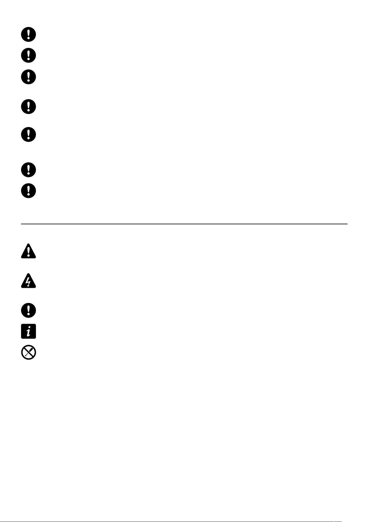
The following symbols are used in this document:
This symbol indicates a potential risk of harm to an individual or damage to the product.
It can also notify the user about instructions that must be strictly followed to ensure safe installation or operation of
the product.
This symbol indicates a potential risk of electrical injury.
It can also notify the user about instructions that must be strictly followed to ensure safe installation or operation of
the product.
This symbol noties the user about instructions that must be strictly followed to ensure proper installation or
operation of the product.
This symbol noties the user about complementary information or optional instructions.
Do not open unless authorized.
This symbol indicates the presence of electrical shock hazards.
It also indicates that no maintenance performed by the end user requires access to internal components.
7 LA-RAK II user manual (EN) version 2.0

Welcome
Welcome
Thank you for purchasing the L-Acoustics LA-RAKII touring rack.
This document contains essential information on using the system properly.
As part of a continuous evolution of techniques and standards, L-Acoustics reserves the right to
change the specications of its products and the content of its document without prior notice. Please
check www.l-acoustics.com on a regular basis to download the latest document and software updates.
LA-RAKII touring rack
LA-RAKII offers worldwide compatibility in one sole model, a universal system that can be used around the globe, thanks
to the three LA12X amplied controllers included and LA-POWERII, compatible with 115V and 230V power distibutions.
LA-RAKII is electrically and mechanically compatible with LA-RAK (LA-RAK BUMP).
LA-RAK II user manual (EN) version 2.0 8
System components
LA Network Manager
System components
Loudspeaker enclosures
Refer to the user manuals of the loudspeaker systems for detailed instructions about the enclosures and their
connection to the amplied controllers.
Powering and driving system
LA12X Amplied controller with DSP, preset library and networking capabilities
LA-RAK II Touring rack containing three LA12X, LA-POWER II for power distribution and LA-PANEL II for
audio and network distribution
Loudspeaker cables
Refer to the user manuals of the loudspeaker systems for detailed instructions about the enclosures and their
connection to the amplied controllers.
Rigging elements
Rigging elements or procedures are not presented in this document.
Refer to the LA-RAKII rigging manual.
Software applications
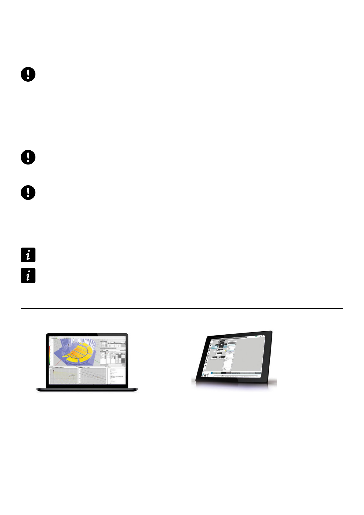
Soundvision 3D acoustical and mechanical modeling software
LA Network Manager Software for remote control and monitoring of amplied controllers
Refer to the Soundvision help.
Refer to the LA Network Manager video tutorial.
Illustrations
Soundvision
9 LA-RAK II user manual (EN) version 2.0
Technical description
Technical description
Main features
LA-RAKII is a 9U rack cabinet in which are mounted three LA12X amplied controllers and two distribution panels: LAPANELII for analog and AES3 audio signal and network, and LA-POWERII for power.
On the front face, an 2U space can receive additional material (such as a switch for L-NET network star topologies).
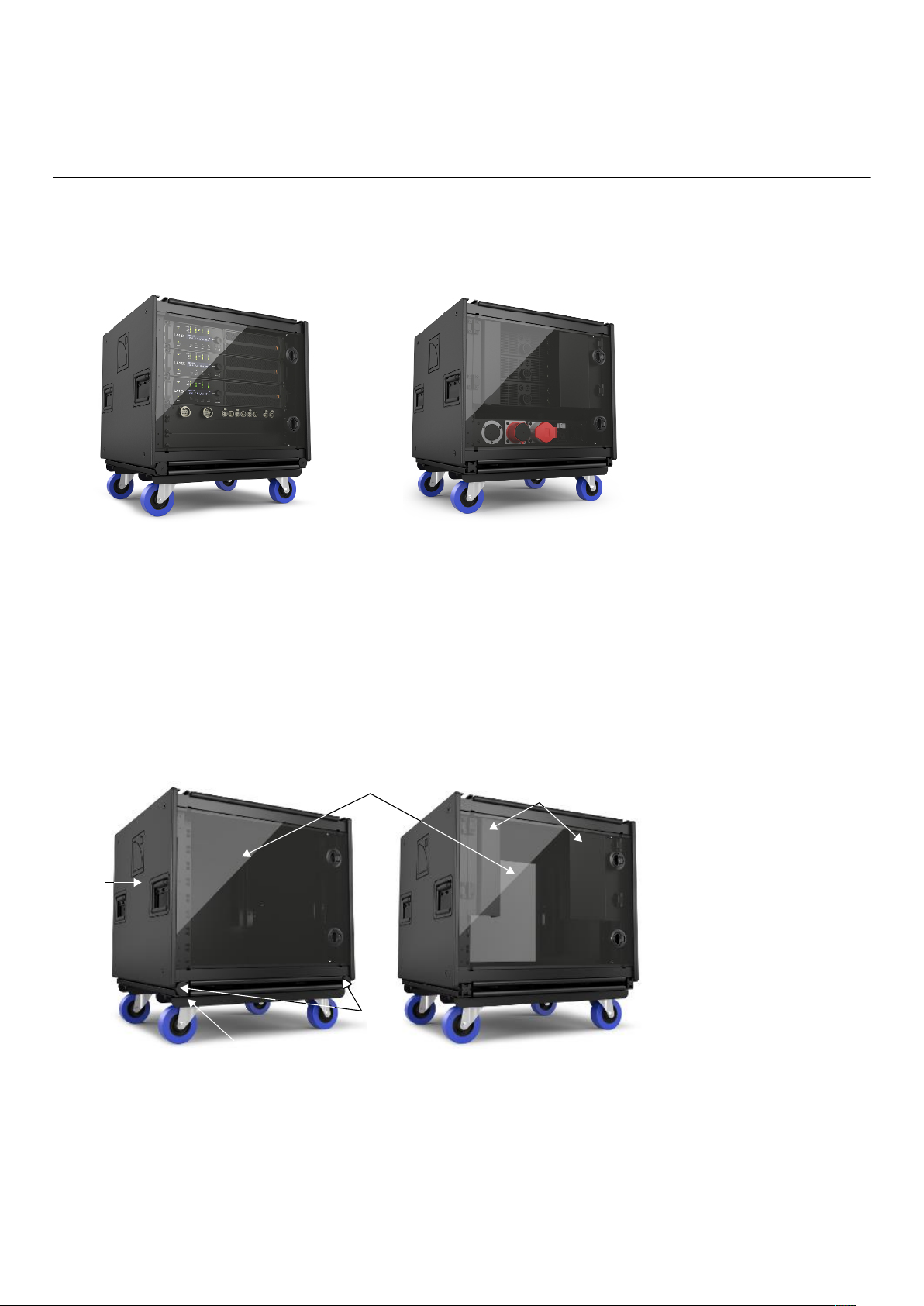
RK9U structure
The LA-RAKII RK9U cabinet is a dual structure consisting of a rubber shock inner steel frame braced by an external
aluminum frame sided with highly resistant polyethylene panels. Two storable LEXAN doors protect the internal
components during transport.
On the rear face, two hinge-mounted panels cover and protect the analog, digital and network connectors of the
amplied controllers. The CA-COM and speakON sockets remains accessible for loudspeaker cabling.
The RK9U is equipped with a detachable transport dolly board and two coupling bars. The coupling bars can also be
used to array several LA-RAKII in own or stacked congurations.
1
3
2
5
4
1 storable LEXAN doors
2 hinge-mounted panels
3 polyethylene panel
4 dolly board
5 coupling bars
LA-RAK II user manual (EN) version 2.0 10
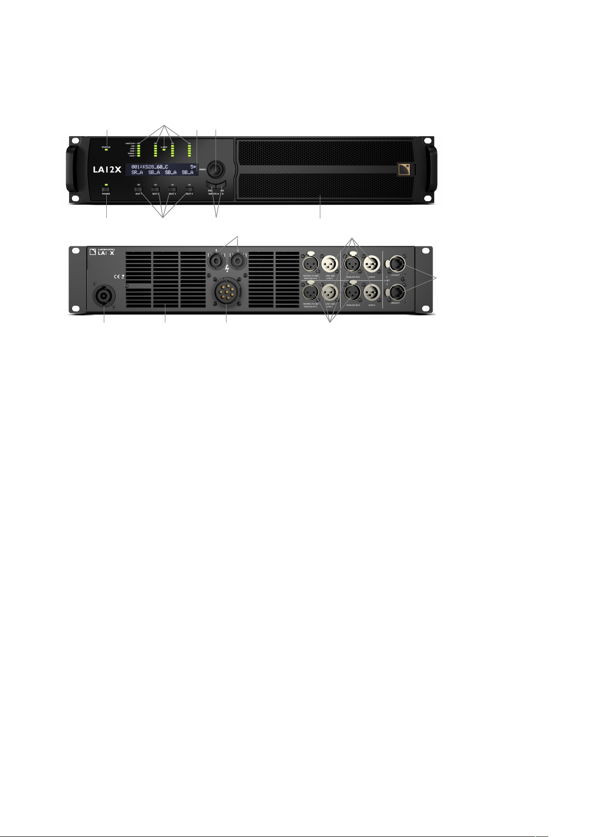
LA12X amplied controller
LA12X is a 2U amplied controller with DSP, preset library and networking capabilities.
Refer to the LA12X user manual for detailed information.
Technical description
6
2
MAINS:
100 - 240 V ~ / 50-60 Hz / 1900 W
OUTPUT PWR PER CH / IMP:
6
2 00 W / 4 Ω
10 11
2
3
7
4
51
OUT1
1+1-
OUT1
A (+)
B ( - )
OUT2
C (+)
D ( - )
8
OUT2
2+2-
CLASS II WIRING
16
12
OUT4
OUT3
1+1-
2+2-
OUT3
E (+)
F ( - )
OUT4
G (+)
H ( - )
9
14
15
13
1 status LED
2 LED meters: 10 powerCON power supply connector (32 A)
— LIMIT/CLIP level 11 outward ventilation grills
— audio levels (-5 dB, -10 dB and -20 dB) 12 speakON output connectors
— SIGNAL presence 13 XLR analog and AES/EBU input connectors
— LOAD presence 14 XLR analog and AES/EBU link connectors
3 L-NET network control LED 15 1 Gb/s etherCON L-NET network connectors
4 2 x 24 characters LCD display 16 CA-COM output connector
5 navigation/edition encoder wheel
6 power/standby key and LED
7 channel selection keys
8 menu keys
9 inward ventilation grill and foam lter
11 LA-RAK II user manual (EN) version 2.0
Technical description
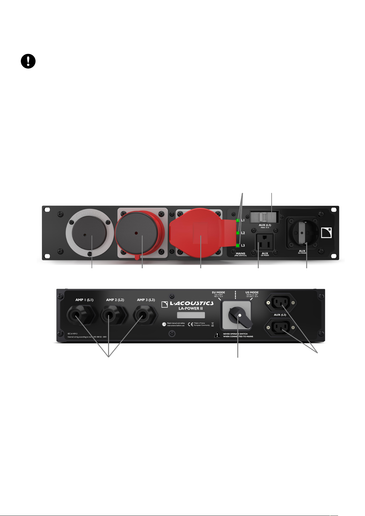
LA-POWERII distribution panel
LA-POWERII is a 2U / 19 inch I/O power distribution panel.
The LA-POWERII is equipped with a mains switch. The factory default settings is EU MODE CEE FORM
400V / 32 A.
To use LA-POWERII in US mode, position the switch on US MODE NEMA L21-30P 120-208 V before
connecting to a power source.
LA-POWERII is equipped with an IN socket for US MODE, one IN and one LINK socket for EU MODE (to power a
secondary rack). Power is automatically balanced with an even number of LA12X per phase.
LA-POWERII is tted with three power cords equipped with 32 A Neutrik powerCON sockets for the LA12X amplied
controller.
Additional outlets (one NEMA, one "Schuko" and two IEC) are available to power auxiliary accessories such as Ethernet
switches and laptop. The auxiliary circuit is protected by a circuit breaker. Refer to section Powering auxiliary devices
(p.18) before use.
Three dual LEDs help monitor phase presence, independently from the mains switch position: their left sides indicate
phase presence at the US IN connector, and their right sides indicate phase presence at the EU IN connector. The LEDs
are for information only. Always apply the necessary safety precautions regardless of the LED status.
1 2
8 9
3
4
1 2
5
6
7
10
1 AC input connector (US mode) 8 AC output cables for LA12X
2 AC input connector (EU mode) 9 mains switch
3 AC link connector (EU mode) 10 AC auxiliary output connector (AUX L3)
4 AC presence LEDs
5 circuit breaker (AUX L3)
6 AC auxiliary output connector (US mode)
7 AC auxiliary output connector (EU mode)
LA-RAK II user manual (EN) version 2.0 12
 Loading...