

L-Acoustics LA12X, LA4X User Manual
LA12X
user manual (en)

Document reference: LA12X user manual (EN) version 4.0
Distribution date: February 6, 2018
©
2018 L-Acoustics. All rights reserved.
No part of this publication may be reproduced or transmitted in any
form or by any means without the express written consent of the
publisher.

Contents
Safety................................................................................................................................................................ 6
Important safety instructions....................................................................................................................... 6
Additional important safety instructions....................................................................................................... 7
Symbols................................................................................................................................................... 8
System components.............................................................................................................................................9
Technical description.........................................................................................................................................10
Main features......................................................................................................................................... 10
Internal components.......................................................................................................................10
Front and rear panels....................................................................................................................10
Signal processing and amplication......................................................................................................... 11
Signal inputs.................................................................................................................................11
DSP architecture............................................................................................................................12
Power supply and amplier section.................................................................................................13
Speaker outputs............................................................................................................................ 13
Speaker protection........................................................................................................................ 13
Monitoring and control............................................................................................................................13
User interface............................................................................................................................... 13
L-NET remote control network......................................................................................................... 13
Installation........................................................................................................................................................14
Mounting................................................................................................................................................14
Ventilation.............................................................................................................................................. 15
Connecting to AC mains......................................................................................................................... 15
Electrical specications.................................................................................................................. 15
Planning the power of the electrical generator................................................................................. 16
Power cord...................................................................................................................................16
Plugging the amplied controller.....................................................................................................17
Power consumption........................................................................................................................17
Heat power calculation..................................................................................................................17
Audio and network cabling..................................................................................................................... 18
Connection panels.........................................................................................................................18
Analog audio............................................................................................................................... 21
Digital audio................................................................................................................................ 22
L-NET........................................................................................................................................... 23
AVB............................................................................................................................................. 23
Speaker........................................................................................................................................23
3

Operation........................................................................................................................................................ 28
Powering on...........................................................................................................................................28
Powering off...........................................................................................................................................28
Setting to standby mode..........................................................................................................................29
Interpreting the front panel LEDs...............................................................................................................29
STATUS........................................................................................................................................ 29
L-NET........................................................................................................................................... 29
Meters..........................................................................................................................................30
OUT.............................................................................................................................................30
Main screen description.......................................................................................................................... 31
Using quick access functions.................................................................................................................... 32
Locking/Unlocking the front panel.................................................................................................. 32
Muting/Unmuting an output channel............................................................................................... 32
Modifying gain............................................................................................................................. 33
Identifying an amplied controller...................................................................................................33
Displaying input level, input selection, input mode and group information........................................... 34
Using the main menu.............................................................................................................................. 35
LOAD PRESET............................................................................................................................... 36
STORE PRESET.............................................................................................................................. 38
DELETE PRESET............................................................................................................................. 39
PRESET PARAMETERS.................................................................................................................... 39
CLEAR GROUP PARAMS................................................................................................................41
INPUT SETTINGS.......................................................................................................................... 42
MONITORING & INFO.................................................................................................................50
OPTIONS..................................................................................................................................... 53
Settings protection...................................................................................................................................57
Maintenance.................................................................................................................................................... 58
Introduction.............................................................................................................................................58
Presentation.................................................................................................................................. 58
Equipment and tools......................................................................................................................58
Screws repair kit...........................................................................................................................59
Troubleshooting and diagnosis................................................................................................................. 59
Interface issues..............................................................................................................................59
L-NET network issues..................................................................................................................... 60
Error messages............................................................................................................................. 61
Sound issues................................................................................................................................. 66
Exploded view........................................................................................................................................ 68
Exploded view - external modules...................................................................................................68
Disassembly and Reassembly procedures.................................................................................................. 69
D/R - grill and foam lter.............................................................................................................. 69
4

D/R - side bracket........................................................................................................................ 70
D/R - rear bracket........................................................................................................................ 71
D/R - rear bracket support screws.................................................................................................. 72
D/R - front handle.........................................................................................................................73
D/R - encoder wheel knob.............................................................................................................74
Quality control........................................................................................................................................75
CHK - External structure and foam lter...........................................................................................75
CHK - Cleanness...........................................................................................................................75
CHK - Normal start-up sequence.................................................................................................... 75
CHK - Network functionalities and rmware.................................................................................... 75
Glossary................................................................................................................................................ 76
Specications................................................................................................................................................... 77
General................................................................................................................................................. 77
Input signal distribution............................................................................................................................78
Analog input.......................................................................................................................................... 79
Digital input........................................................................................................................................... 79
Latency...................................................................................................................................................79
AVB input.............................................................................................................................................. 79
Automatic fallback option........................................................................................................................ 80
Remote control and monitoring.................................................................................................................80
Physical data.......................................................................................................................................... 80
Approvals........................................................................................................................................................ 81
5
Safety
Safety
Important safety instructions
Explanation of graphical symbols
The lightning ash with arrowhead symbol within an equilateral triangle is intended to alert the user
to the presence of uninsulated "dangerous voltage" within the product's enclosure that may be of
sufcient magnitude to constitute a risk of electric shock to persons.
The exclamation point within an equilateral triangle is intended to alert the user to the presence of
important operating and maintenance instructions in the literature accompanying the product.
1. Read these instructions.
2. Keep these instructions.
3. Heed all warnings.
4. Follow all instructions.
5. Do not use this apparatus near water.
6. Clean only with dry cloth.
7. Do not block any ventilation openings. Install in accordance with the manufacturer's instructions.
8. Do not install near any heat sources such as radiators, heat registers, stoves, or other apparatus (including
ampliers) that produce heat.
9. Do not defeat the safety purpose of the grounding-type plug. A grounding-type plug has two blades and a third
grounding prong. The third prong is provided for your safety. If the provided plug does not t into your outlet,
consult an electrician for replacement of the obsolete outlet.
10. Protect the power cord from being walked on or pinched particularly at plugs, convenience receptacles, and the
point where they exit from the apparatus.
11. Only use attachments/accessories specied by the manufacturer.
12. Use only with the cart, stand, tripod, bracket, or table specied by the manufacturer, or sold with the
apparatus. When a cart is used, use caution when moving the cart/apparatus combination to avoid
injury from tip-over.
13. Unplug this apparatus during lightning storms or when unused for long periods of time.
14. Refer all servicing to qualied service personnel. Servicing is required when the apparatus has been damaged in
any way, such as power-supply cord or plug is damaged, liquid has been spilled or objects have fallen into the
apparatus, the apparatus has been exposed to rain or moisture, does not operate normally, or has been dropped.
15. WARNING: To reduce the risk of re or electric shock, this apparatus should not be exposed to rain or moisture
and objects lled with liquids, such as vases, should not be placed on this apparatus.
16. To completely disconnect this equipment from the mains, disconnect the power supply cord plug from the
receptacle.
Pour déconnecter complètement l'appareil du secteur, débranchez la prise de la che secteur.
17. The main plug of the power supply cord shall remain readily accessible.
La prise principale du cordon d'alimentation doit rester totalement accessible.
6 LA12X user manual (EN) version 4.0
Safety
Additional important safety instructions
Verify the electrical conformity and compatibility of the mains supply.
Only connect the product to an AC power outlet rated 100-240 V, 50-60 Hz, with the following current values:
100-120 V: 30 A
200-240 V: 16 A
WARNING: The product is of CLASS 1 construction and shall be connected to a mains socket outlet with a
protective connection to earth.
When the product is used in a three-phase circuit, verify the electrical conformity and
compatibility of the three-phase circuit.
Verify that the three phases work, and balance the loads between the three phases.
Verify that the neutral and earth work.
Never try to emulate a 230 V circuit connecting an apparatus to two live wires of a 120 V three-phase circuit.
Never try to emulate a 200 V circuit connecting an apparatus to two live wires of a 100 V three-phase circuit.
Always interconnect a Class C circuit breaker between the product and the mains supply.
The circuit breaker current rating depends on the mains voltage rating, as follows:
100-120 V: 30 A
200-240 V: 16 A
Electrical generator
You must power on the generator before powering on the product.
Verify that the product is turned off before powering on the generator.
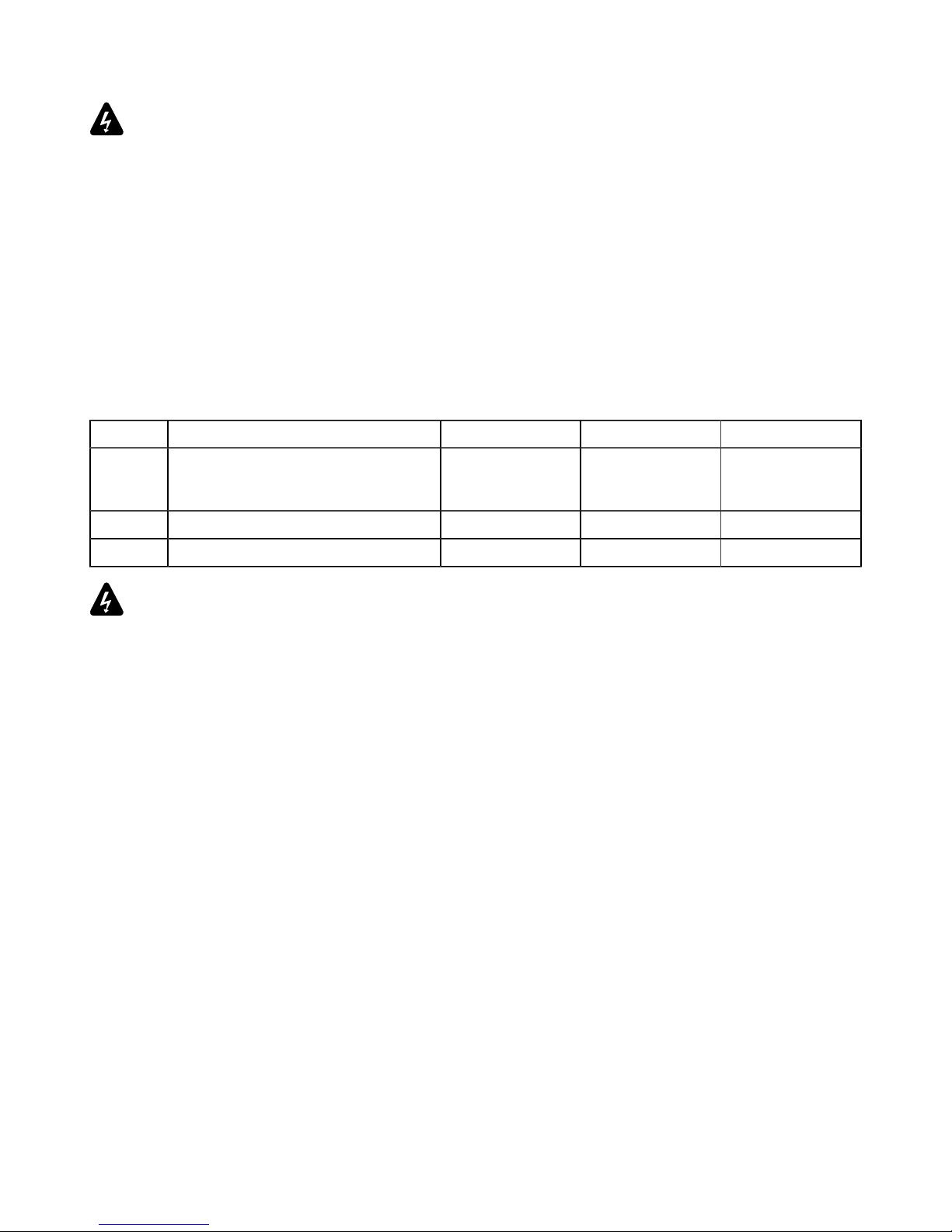
Terminals marked with the lightning ash symbol are HAZARDOUS LIVE.
The external wiring connected to these terminals requires installation by an instructed person or
the use of ready-made leads or cords.
Never attempt to touch any exposed speaker wiring while the product is operating: rst disconnect the
connector from the product.
Mute all output channels before connecting a speaker to an amplied controller.
Do not connect a speaker output in parallel or series with any output of another amplied controller.
Do not connect the speaker outputs to any other voltage source, such as a battery, power mains, or
power supply, regardless of whether the amplied controller is turned on or off.
Never incorporate equipment or accessories not approved by L-Acoustics.
Read all the related PRODUCT INFORMATION documents shipped with the products before
exploiting the system.
Beware of sound levels.
Do not stay within close proximity of loudspeakers in operation.
Loudspeaker systems are capable of producing very high sound pressure levels (SPL) which can instantaneously
lead to permanent hearing damage to performers, production crew and audience members. Hearing damage
can also occur at moderate level with prolonged exposure to sound.
Check the applicable laws and regulations relating to maximum sound levels and exposure times.
Beware of over power risks.
Only use compatible loudspeakers with appropriate presets to avoid damage to the loudspeakers.
Inspect the product before operation.
If any sign of defect or damage is detected, immediately withdraw the product from use for maintenance.
This product is intended for use by trained personnel.
Do not use the product outside its operating temperature range.
The product operates at a room temperature between 0° C / 32° F and 50° C / 122° F.
Do not expose the product to direct sun.
LA12X user manual (EN) version 4.0 7
Welcome
Only use the product in a conformed electro-magnetic environment.
Conformed environments are: E1 (residential), E2 (commercial and light industrial), E3 (urban outdoors), E4
(controlled EMC environment, ex. TV studio), E5 (heavy industrial), as per EN55103-2 standards.
Avoid radio interference.
This product has been tested and complies with the limits indicated in the EMC directive (Electro Magnetic
Compatibility). These limits are designed to provide reasonable protection against harmful interference from
electrical equipment, but it cannot be guaranteed that interference will never occur.
Read the maintenance section of this document before servicing the product.
Shipping
Use the original packaging for shipping the product, unless it is mounted in a rack with the front and rear panels
xed to the rack, as described in this manual.
Symbols
The following symbols are used in this document:
This symbol indicates a potential risk of harm to an individual or damage to the product.
It can also notify the user about instructions that must be strictly followed to ensure safe installation or operation of
the product.
This symbol indicates a potential risk of electrical injury.
It can also notify the user about instructions that must be strictly followed to ensure safe installation or operation of
the product.
This symbol noties the user about instructions that must be strictly followed to ensure proper installation or
operation of the product.
This symbol noties the user about complementary information or optional instructions.
Do not open unless authorized.
This symbol indicates the presence of electrical shock hazards.
It also indicates that no maintenance performed by the end user requires access to internal components.
Welcome
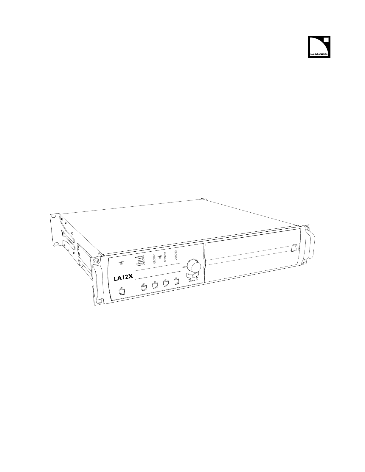
Thank you for purchasing the L-Acoustics LA12X amplied controller.
This document contains essential information on using the system properly.
As part of a continuous evolution of techniques and standards, L-Acoustics reserves the right to
change the specications of its products and the content of its document without prior notice. Please
check www.l-acoustics.com on a regular basis to download the latest document and software updates.
LA12X amplied controller
L-Acoustics amplied controllers offer high performance and efcient loudspeaker amplication, digital signal processing
and comprehensive system protection in a single ergonomic package. The onboard preset library allows for rapid system
optimization with minimum EQ correction and delivers a unique sonic signature across all L-Acoustics systems.
The LA12X is the most powerful unit in the range. Thanks to its DSP-controlled, universal Switched Mode Power Supply
with advanced Power Factor Correction, it delivers high output power with outstanding hold times even on less-thanideal A/C mains. It offers maximum versatility with its 4x4 architecture and its ability to drive all L-Acoustics loudspeaker
enclosures including the KS28 reference subwoofer.
8 LA12X user manual (EN) version 4.0

System components
System components
Loudspeaker enclosures
Refer to the user manuals of the loudspeaker systems for detailed instructions about the enclosures and their
connection to the amplied controllers.
Powering and driving system
Racks
LA-RAK II Touring rack containing three LA12X, LA-POWER II for power distribution and LA-PANEL II for
audio and network distribution
L-CASE 2U Electronics transport and protection case
Loudspeaker cables
Refer to the user manuals of the loudspeaker systems for detailed instructions about the enclosures and their
connection to the amplied controllers.
Software applications
Soundvision 3D acoustical and mechanical modeling software
LA Network Manager Software for remote control and monitoring of amplied controllers
Refer to the Soundvision help.
Refer to the LA Network Manager help.
Illustrations
LA Network Manager LA-RAK II
LA12X user manual (EN) version 4.0 9
Technical description
Technical description
Main features
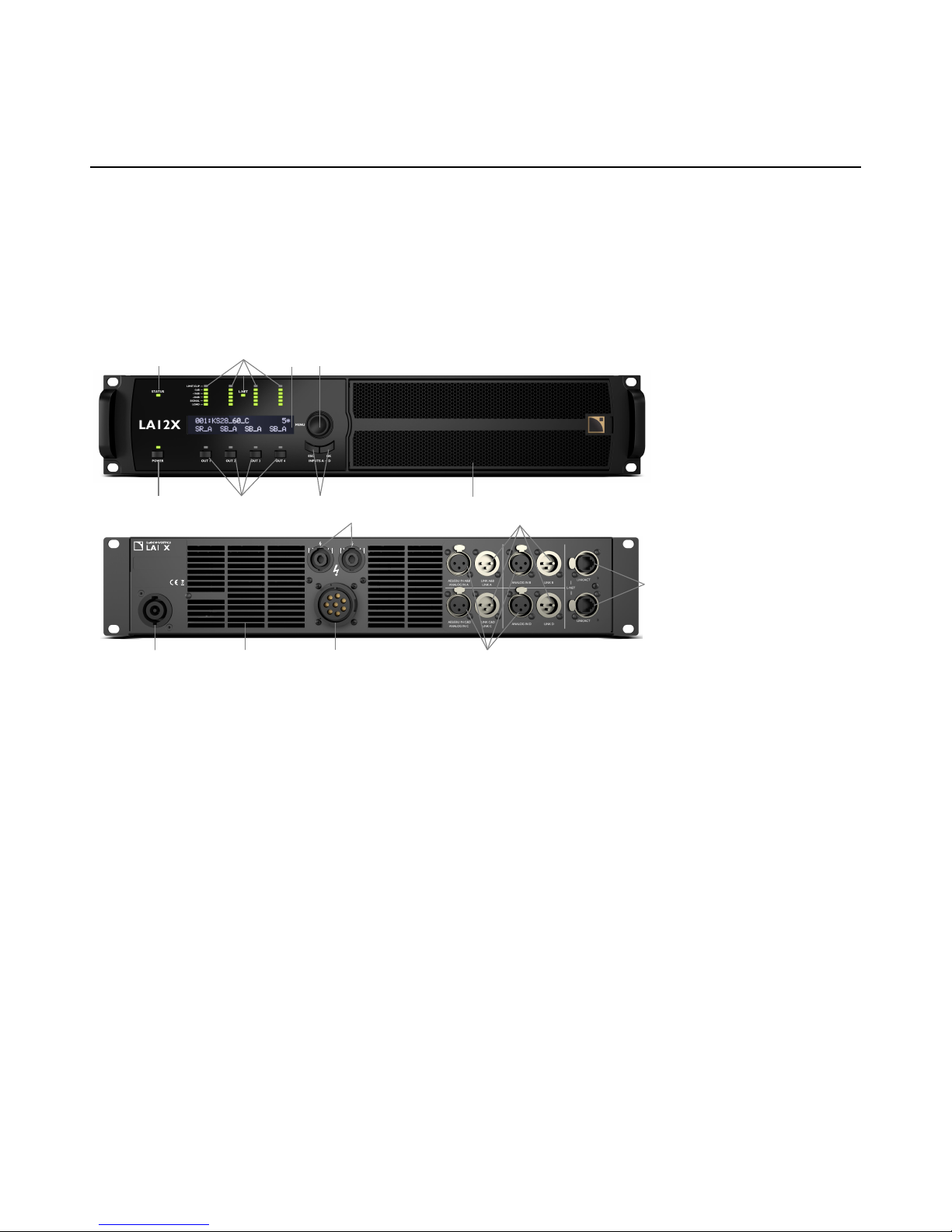
Internal components
The core of the LA12X is a dual DSP engine driving four channels of amplication from four inputs. The LA12X also
features a ash memory for preset storage and management, high performance A/D-D/A converters and AES/EBU
inputs for audio signals, a universal SMPS (Switched Mode Power Supply) with PFC (Power Factor Correction), a front
panel user interface, and a 1 Gb/s dual port Ethernet device for networked remote control.
Front and rear panels
51
2
3
4
6
7
8
9
10 11
12
13
14
15
16
OUT2
MAINS:
100 - 240 V ~ / 50-60 Hz / 1900 W
OUTPUT PWR PER CH / IMP:
2 00 W / 4 Ω
2
OUT1
1+1-
2+2-
OUT3
1+1-
OUT4
2+2-
CLASS II WIRING
OUT1
OUT2
OUT3
OUT4
A (+)
B ( - )
C (+)
D ( - )
E (+)
F ( - )
G (+)
H ( - )
6
1 status LED
2 LED meters: 10 powerCON power supply connector (32 A)
— LIMIT/CLIP level 11 outward ventilation grills
— audio levels (-5 dB, -10 dB and -20 dB) 12 speakON output connectors
— SIGNAL presence 13 XLR analog and AES/EBU input connectors
— LOAD presence 14 XLR analog and AES/EBU link connectors
3 L-NET network control LED 15 1 Gb/s etherCON L-NET network connectors
4 2 x 24 characters LCD display 16 8-point output connector
5 navigation/edition encoder wheel
6 power/standby key and LED
7 channel selection keys
8 menu keys
9 inward ventilation grill and foam lter
10 LA12X user manual (EN) version 4.0

Technical description
Signal processing and amplication
Signal inputs
The LA12X features four input connectors allowing it to receive four analog signals, four digital signals, or two analog
and two digital signals, depending on the input mode selected by the user — see section XLR INPUT MODE (p.44).
This architecture also allows digital-to-analog or digital-to-digital fallback.
In addition, four channels may be retrieved from an AVB stream containing up to 16 channels at 48 kHz or 96 kHz,
connected by one of the two 1 Gb/s Ethernet ports.
Analog
The LA12X can be fed with up to four balanced analog audio signals using XLR female input connectors ANALOG IN A
to ANALOG IN D — see illustration in section Front and rear panels (p.10). Each analog input port is ESD protected.
The analog input panel also features four XLR male link connectors passively wired to the input connectors. The link
connectors allow transmitting the input signals to daisy-chained amplied controllers. Each analog link port is ESD
protected.
The analog signal must be converted into a digital signal to be processed by the DSP. For this purpose, the LA12X
amplied controller is tted with four cascaded 24-bit A/D converters with a sampling rate of 96 kHz allowing an
encoding dynamic range of 130 dB.
AES/EBU
The LA12X can be fed with up to four AES/EBU digital audio signals (transported in pairs) using XLR input connectors
AES/EBU IN A&B and AES/EBU IN C&D.
Each AES/EBU input port is an XLR female connector. The audio signals can come from a digital mixing desk or a digital
audio network bridge compliant with the AES/EBU (AES3) digital audio standards. Each AES/EBU input port is ESD
protected and transformer balanced.
The AES/EBU input panel also features two XLR male link ports actively connected to the input ports (with failsafe relay
in case of mains absence). The link connectors allow transmitting the input signals to daisy-chained amplied controllers.
Each AES/EBU link port is ESD protected and transformer balanced.
Each AES/EBU input port is equipped with a SRC (Sample Rate Converter) that has been selected to support a wide
range of input formats (16 - 24 bits / 44.1 - 192 kHz). The SRC converts the formats to the 24 bits/96 kHz internal
format used by the amplied controller. The SRC is a high-quality hardware component (140 dB dynamic range,
THD+N<-120dBFS, strong input jitter attenuation) and provides constant propagation delay regardless of the input
sampling frequency.
There is no external synchronization mode. The amplied controller's clock runs using its high-precision internal quartz
at 96 kHz (or on the clock of the connected AVB input stream). This ensures low jitter and high audio quality in live
conditions (large cable lengths, large number of amplied controllers) while preventing phase shift, as required for line
source systems.
Digital domain benets
Keeping the signal in the digital domain will provide the following benets (with any digital mixing desk or any audio
network) compared to the analog signal distribution:
• Better audio quality by removing one D/A - A/D cycle.
• Optimized level chain by removing the risk of level misalignment between console and amplied controllers.
• Digital signal refreshed at each amplied controller in a daisy-chain.
• Improved maximum cable length. The LA12X has been tested with up to 305 m/1000 ft of 3 models of AES/EBU
rated cables (single cuts, digital source signal running at Fs = 48 kHz):
• 1696A from BELDEN INC.
• OT234H from KLOTZ communications GmbH.
• SC-BINARY 234 from SOMMER CABLE GmbH.
LA12X user manual (EN) version 4.0 11
Technical description
AVB
One AVB stream of up to 16 channels may be connected to LA12X. LA12X retrieves up to four channels from this stream.
Each Ethernet port uses a high speed data transfer protocol up to 1 Gb/s and supports the IEC 61883-6 AM824 stream
format with stream frequencies of 48 or 96 kHz.
The amplied controller synchronizes its audio clock on the clock used by the talker using the incoming stream.
LA12X embed an AVB bridge and may therefore be used to create an AVB network.
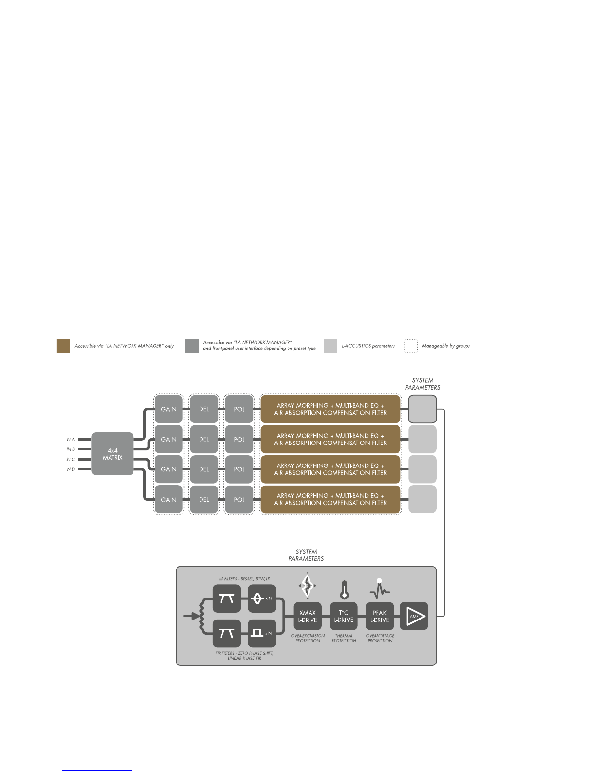
DSP architecture
The proprietary algorithms allow optimum performance and protection of each individual transducer of the L-Acoustics
systems for an even more natural, transparent and realistic sound experience.
• The DSP engine is a 32-bit oating point DSP at 96 kHz sampling rate providing an enhanced dynamic range since
it does not generate calculation clips like a xed point DSP.
• A dedicated engineering approach combining IIR and FIR lters generates perfectly linearized phase curves and
signicantly improved impulse responses.
• The 4 x 4 matrix architecture offers exibility for various system congurations.
• A delay of up to 1000 ms can be set for each output channel.
• The L-DRIVE transducer protection system offers advanced protection by simultaneously monitoring the excursion and
the temperature of the transducer.
• With a complete factory preset library and the possibility to create additional user presets, the ash memory
provides a quick access to all the usual L-Acoustics speaker system congurations (refer to the Preset Guide).
audio path parameters
12 LA12X user manual (EN) version 4.0
Technical description
Power supply and amplier section
The LA12X is a green amplied controller that relies on a universal SMPS (Switch Mode Power Supply) suitable for
mains from 100 to 240 V (±10 %). The SMPS features a PFC (Power Factor Correction) which maximizes the amplier
efciency and takes advantage of nearly 100 % of the electrical power available with a very high tolerance to unstable
mains. This represents a reduction of the electrical power requirements (cable gauge, power conditioning, etc.) for
substantial savings.
The Class D amplication circuits ensure the LA12X energy-efciency for minimal heat dissipation. LA12X delivers
4x1400 W RMS at 8 Ω, 4x2600 W RMS at 4 Ω or 4x3300 W RMS at 2.7 Ω.
Speaker outputs
The LA12X features two 4-point speakON connectors and one 8-point connector for loudspeaker outputs.
Speaker protection
The L-DRIVE transducer protection system provides a dual analysis of both signal intensity and voltage in real-time and
RMS. Under extreme conditions, when component membranes reach the over-excursion zone or if the coil temperature
reaches a critical point, L-DRIVE is activated and acts as a power regulator.
As a result, the amount of power delivered at any channel is adjusted to the dynamic and thermal capacity of each
individual transducer.
Monitoring and control
User interface
The front panel user interface provides:
• Real-time monitoring functionalities via the LED display (signals presence and level) and the LCD screen (system
parameters).
• Instant access to navigation and parameters control using the encoder wheel and the six keys .
See also illustration in section Front and rear panels (p.10).
Refer to section Operation (p.28) for detailed operating instructions.
L-NET remote control network
The integration of the L-NET Ethernet-based network, with its high speed data transfer protocol up to 1 Gbit/s, allows up
to 253 amplied controllers to be controlled and monitored in real-time from LA Network Manager.
Multiple network topologies such as daisy-chain, star and hybrid are congurable. The computer running LA Network
Manager and the amplied controllers are connected to each other using industry standard CAT5e U/FTP cables (or
higher category) tted with RJ45 connectors.
The LA12X connects to the network via the two etherCON sockets located on its rear panel.
Refer to the LA Network Manager Help for detailed operating instructions.
Third party management solutions
L-Acoustics provides SNMP support to facilitate the integration via third party control and monitoring systems.
As a certied member of the Crestron® and Extron® partner programs, L-Acoustics also provides software
modules allowing control integration into their automation systems.
Crestron is a trademark or registered trademark of Crestron Electronics, Inc. in the United States, other countries or both..
Extron is a registered trademark of Extron Elctronics..
LA12X user manual (EN) version 4.0 13
Installation
Installation
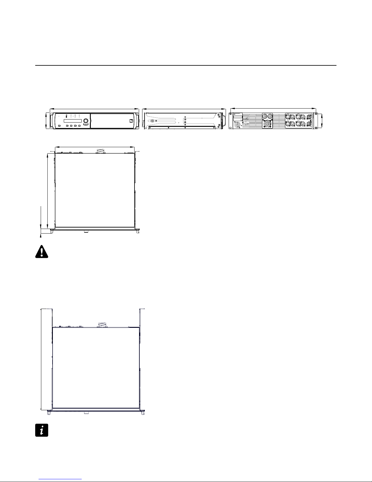
Mounting
The LA12X is two rack units high (2U) and can be mounted in an EIA-standard 19” rack using the four points on the front
panel. Use the xing material provided by the rack manufacturer to mount the controller to the rack front rails.
LA12X dimensions
483 mm / 19 in
88 mm / 3.5 in
76.20 mm / 3 in
465 mm / 18.3 in
LA12X
454.7 mm / 17.87 in
433 mm / 17.04 in
419.1 mm / 16.50 in
23.6 mm / 0.93 in
STATUS
LIMIT/CLIP
-5dB
-10dB
-20dB
SIGNAL
LOAD
LA12X
L-NET
MENU
ESC OK
INPUTS A ~ DOUT 1 OUT 2 OUT 3 OUT 4POWER
Risk of damaging the amplied controller during transport
During transport or while on tour the amplied controller should be rear supported in addition to the front panel
mounting.
Use the rear brackets provided with the amplied controller.
Any mechanical damage to the amplied controller used in portable applications without rear support is not
covered by warranty.
LA12X with rear rack support brackets
max. 534.3 mm / 21.02 in
LA-RAK II touring rack
The LA-RAK II touring rack contains three LA12X, and panels for power, audio and network distribution.
Refer to the LA-RAK II user manual.
14 LA12X user manual (EN) version 4.0
Installation
Ventilation
To maintain moderate operating temperatures, the LA12X is equipped with fans providing front to rear airow.
Ventilation instructions
Install the controller in an open area so that the front and rear panels are located at a minimum distance of 30 cm
from any external object or structure.
Ensure the front foam lter is clean and dirt free.
Do not block the front and rear ventilation grills.
Ventilation when rack-mounted
Do not block the ventilation grills with front or back panels or doors. If not possible, use a forced-ventilation
system.
When stacking more than one controller in a rack, mount them directly on top of each other or close any open
space in the rack with blank panels.
Connecting to AC mains
Electrical specications
AC mains specications
Verify the electrical conformity and compatibility of the mains supply.
Only connect the product to an AC power outlet rated 100-240 V, 50-60 Hz, with the following current values:
100-120 V: 30 A
200-240 V: 16 A
WARNING: The product is of CLASS 1 construction and shall be connected to a mains socket outlet with a
protective connection to earth.
Three-phase circuit
When the product is used in a three-phase circuit, verify the electrical conformity and
compatibility of the three-phase circuit.
Verify that the three phases work, and balance the loads between the three phases.
Verify that the neutral and earth work.
Never try to emulate a 230 V circuit connecting an apparatus to two live wires of a 120 V three-phase circuit.
Never try to emulate a 200 V circuit connecting an apparatus to two live wires of a 100 V three-phase circuit.
Circuit breaker
Always interconnect a Class C circuit breaker between the product and the mains supply.
The circuit breaker current rating depends on the mains voltage rating, as follows:
100-120 V: 30 A
200-240 V: 16 A
LA12X user manual (EN) version 4.0 15
Installation
Planning the power of the electrical generator
Electrical generator
You must power on the generator before powering on the product.
Verify that the product is turned off before powering on the generator.
LA12X draws 16 A from 230 V.
A typical generator has a power factor of 0.8 and should operate at 70% load for good efciency.
The kVA provision for one LA12X should therefore be:
(16 A x 230 V) / (0.8 x 70 %) = 6.5 kVA
This calculation is an example using typical values. It can be adapted using the table in section Power consumption
(p.17).
Power cord
The removable power cord is tted at one end with a 32 A powerCON connector.
The other end and the wires color code depends on the cord type, as follows:
type plug live neutral ground
CE
CN
CEE 7/7, 16 A / 250 V, grounded
GB1002 GB2099, 16 A
brown blue green/yellow
US NEMA L5-30P, 30 A / 125 V, grounded black white green
INT bare ends (local power plug to be tted) black white green/yellow
Strictly apply the specic safety regulations of the country of use.
Do not defeat the ground connection of the supplied power cord using an adaptor or any other methods.
A suitable plug must be wired to the INT power cord.
Verify that the plug conforms to the specic voltage and current rating given in section Electrical specications
(p.15).
16 LA12X user manual (EN) version 4.0
Installation
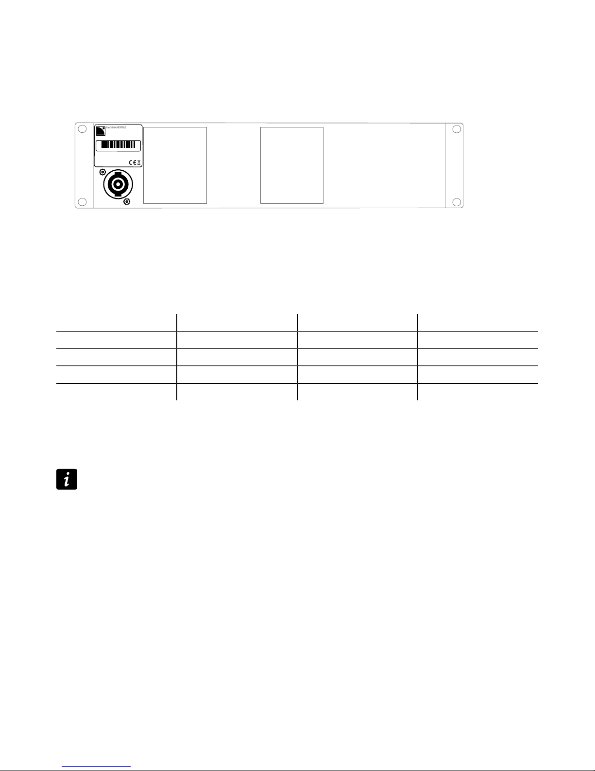
Plugging the amplied controller
How to plug the amplied controller to the AC mains.
Procedure
— First, connect the powerCON to the amplied controller mains panel.
MAINS:
100 - 240V ~ / 50-60 Hz / 1900 W
OUTPUT PWR PER CH / IMP:
2600 W / 4 Ω
1110000010
LA12X
— Then, connect the power plug to the mains socket.
Following this order improves the powerCON longevity.
Power consumption
The LA12X power requirements depend on the load impedance and the signal level.
Mains input power and current draw (all channels driven)
Maximum output power 4 x 1400 W RMS at 8 Ω 4 x 2600 W RMS at 4 Ω 4 x 3300 W RMS at 2.7 Ω
1/3 output power (-5dB) 10.5 A / 2300 W 19 A / 4200 W 26 A / 5500 W
1/8 output power (-9 dB) 4.8 A / 1050 W 8.1 A / 1850 W 11.5 A / 2400 W
Idle 1 A / 160 W 1 A / 160 W 1 A / 160 W
Standby 0.6 A / 10 W 0.6 A / 10 W 0.6 A / 10 W
Current values given for mains rated at 230 V. Multiply by:
• 2.3 for 100 V
• 1.9 for 120 V
• 1.15 for 200 V
Output power references
A third of the maximum output power corresponds to the worst case scenario of a program source using highly
compressed music or pink noise with amplied controller driven to clip level.
An eighth of the maximum output power corresponds to a loud music program with a small dynamic range and
9dB of headroom (IEC standard power rating).
Heat power calculation
If a 4 Ω load is connected to each output channel of the LA12X, each channel delivers up to 2600 W.
With a standard use at 1/8 of full power (9 dB headroom), the power delivered per channel is:
2600 / 8 = 325, so a total power of 4 x 325 = 1300 W.
According to the table in section Power consumption (p.17), the LA12X power consumption is 1850 W. The heat
power produced is then (difference between power consumption and output power):
1850 - 1300 = 550 W
LA12X user manual (EN) version 4.0 17
Installation
Audio and network cabling
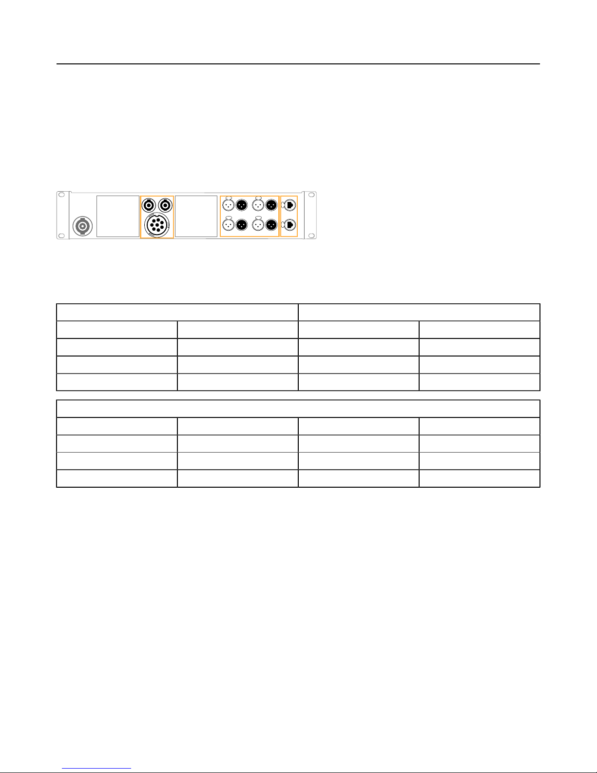
Connection panels
The amplied controller's rear side features three panels for audio and network cabling:
• A speaker panel (1) to connect the loudspeakers.
• A signal panel (2) to connect the analog and/or digital (AES/EBU) audio sources and link the signals to another
amplied controller.
• An L-NET panel (3) to connect to a network and be remotely controlled by LA Network Manager.
LA12X audio and network connection panels
1 2
3
Speaker panel
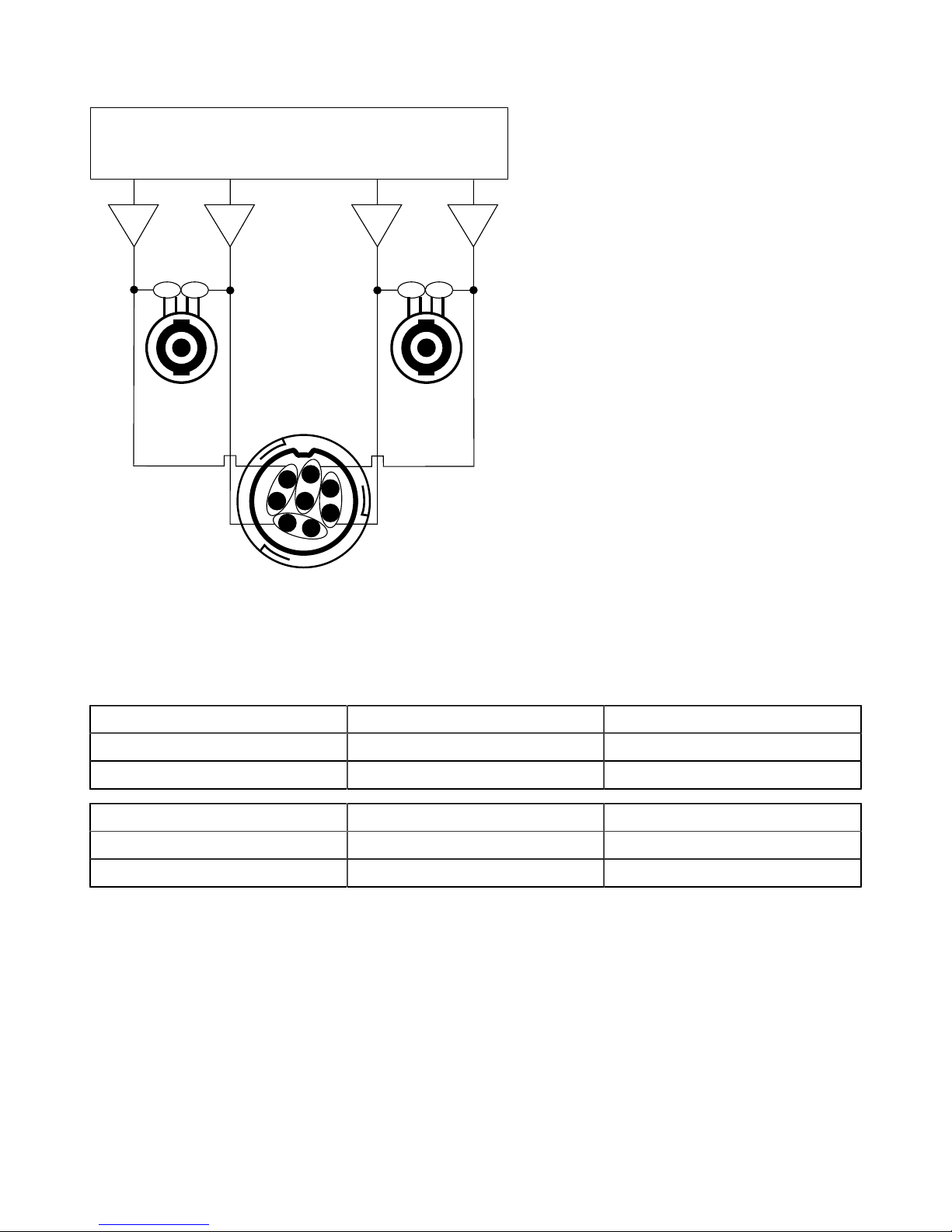
The two 4-point speakON connectors and the 8-point connector on the rear panel are for loudspeaker connection. They
are wired as follows:
left speakON connector right speakON connector
Pin 1+ Out 1+ Pin 1+ Out 3+
Pin 1 - Out 1 - Pin 1 - Out 3 -
Pin 2+ Out 2+ Pin 2+ Out 4+
Pin 2 - Out 2 - Pin 2 - Out 4 -
8-point output connector
Pin A Out 1+ Pin E Out 3+
Pin B Out 1 - Pin F Out 3 -
Pin C Out 2+ Pin G Out 4+
Pin D Out 2 - Pin H Out 4 -
18 LA12X user manual (EN) version 4.0
Installation
output audio paths
DSP
OUT 1
OUT 2
OUT 3
OUT 4
1+ 1- 2+ 2- 1+ 1- 2+ 2-
A
B
C
D
E
F
G
H
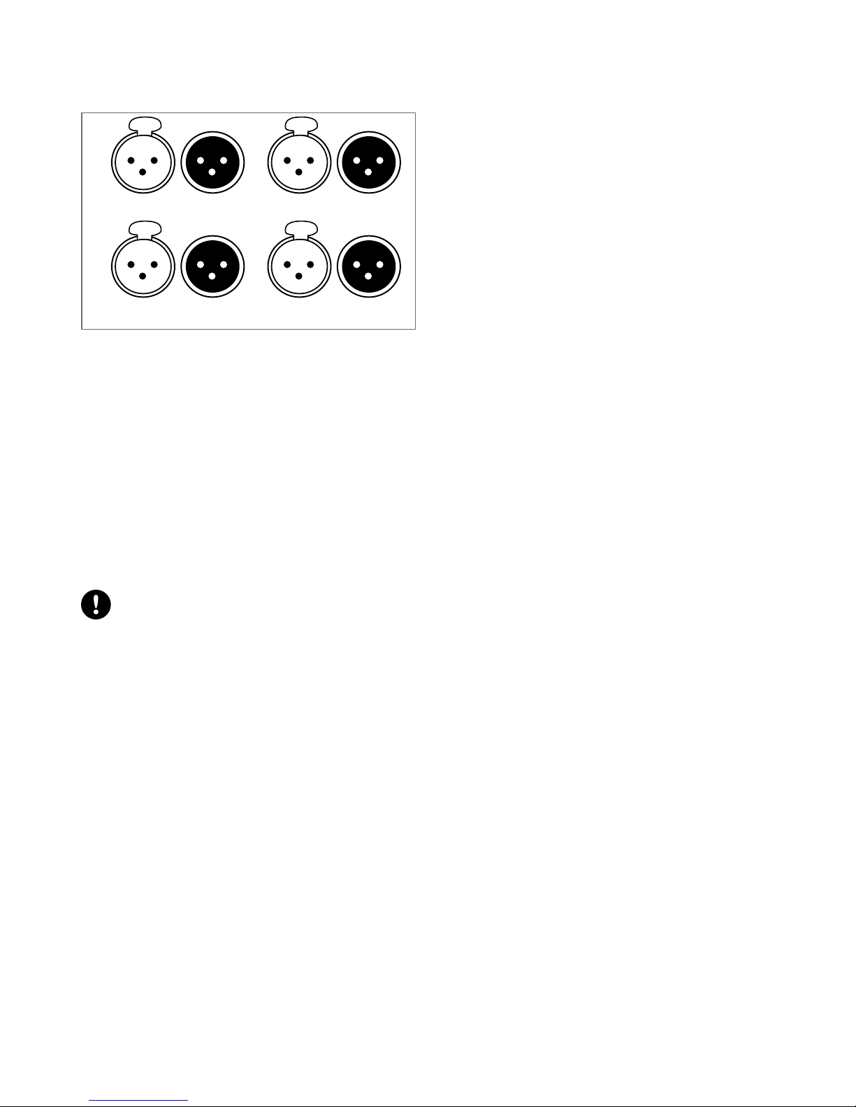
Signal panels
The eight XLR connectors on the rear panel are for analog or digital signal cabling.
The XLR connectors can transport analog or digital signals depending on the input mode selected by the user for channel
pairs AB and CD (the two selections can be different). Connections to the IN connectors are referenced in the table. Refer
also to section XLR INPUT MODE (p.44).
input mode AB IN A / IN A&B IN B
Analog analog audio source (1 channel) analog audio source (1 channel)
AES/EBU digital audio source (2 channels) not used
input mode CD IN C / IN C&D IN D
Analog analog audio source (1 channel) analog audio source (1 channel)
AES/EBU digital audio source (2 channels) not used
LA12X user manual (EN) version 4.0 19
Installation
Each LINK connector is wired to the corresponding IN connector, and thus transports the same type of signal.
LA12X signal panel
AES/EBU IN A&B
ANALOG IN A
AES/EBU IN C&D
ANALOG IN C
LINK A&B
LINK A
LINK C&D
LINK C
ANALOG IN B
ANALOG IN D
LINK B
LINK D
Analog input mode
The XLR connectors are wired according to IEC 60268-12:
• pin 1: shield
• pin 2: + signal
• pin 3: - signal
The female XLR input connectors ANALOG IN A to ANALOG IN D can receive up to four analog signals (when setting
the analog input mode for channel pairs AB and CD). The headroom of the input circuits is high enough to accept the
maximum output level from virtually any line level signal source (up to 22 dBu).
Each LINK connector is passively wired in parallel to the corresponding IN channel. The input impedance is high enough
(22 kΩ, balanced) to allow multiple parallel input connections.
AES/EBU input mode
Digital audio source specications
Standard: AES/EBU (AES3)
Sampling frequency: 44.1, 48, 88.2, 96, 176.4 or 192 kHz
Word length: 16, 18, 20 or 24 bits
The AES/EBU inputs are transformer balanced and their XLR connectors are wired according to IEC 60268-12.
The female XLR input connectors AES/EBU IN A&B and AES/EBU IN C&D can receive up to four digital signals (when
setting the AES/EBU input mode for channel pairs AB and CD). The input format is AES/EBU (AES3).
Each LINK connector is electronically buffered to allow daisy-chaining any number of amplied controllers. It also features
a failsafe relay to ensure wiring continuity in case of amplied controller shutdown.
L-NET panel
The two etherCON connectors are for the remote control of LA12X over an Ethernet network called L-NET using LA
Network Manager.
Each of the two etherCON connectors can be equally used as an IN or a LINK connector.
20 LA12X user manual (EN) version 4.0
Installation
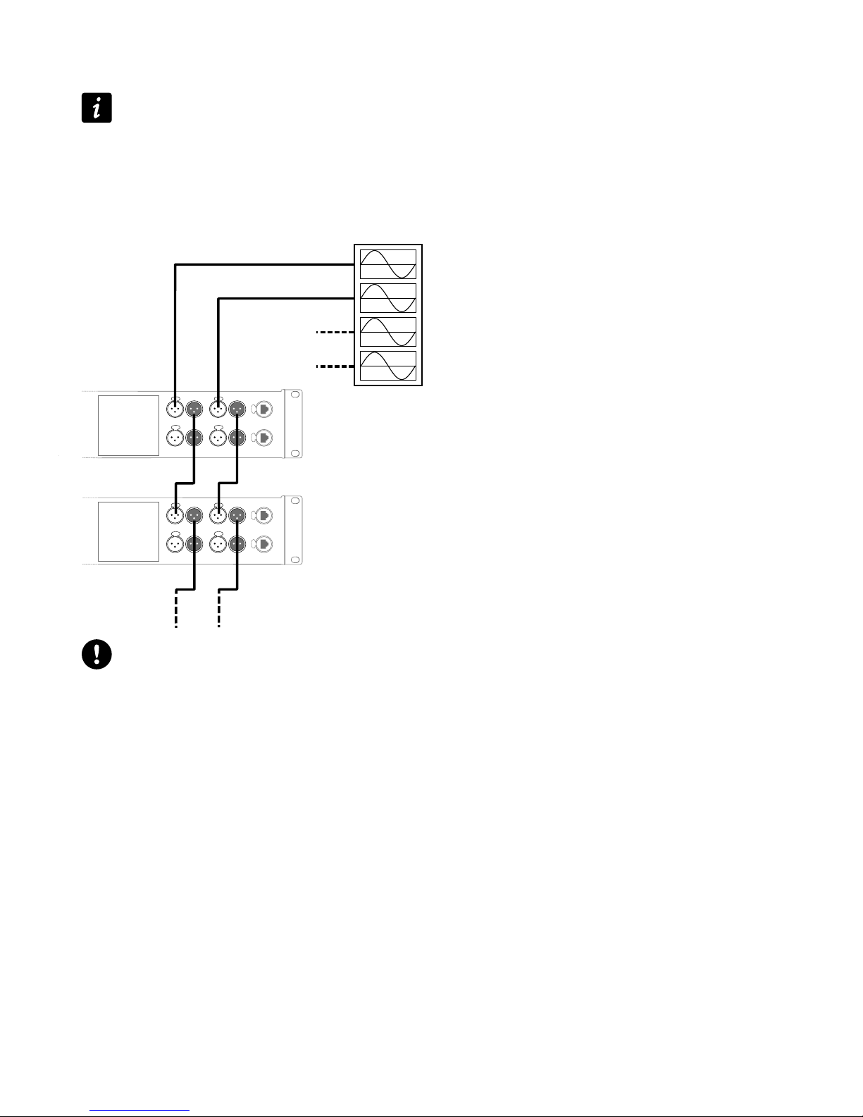
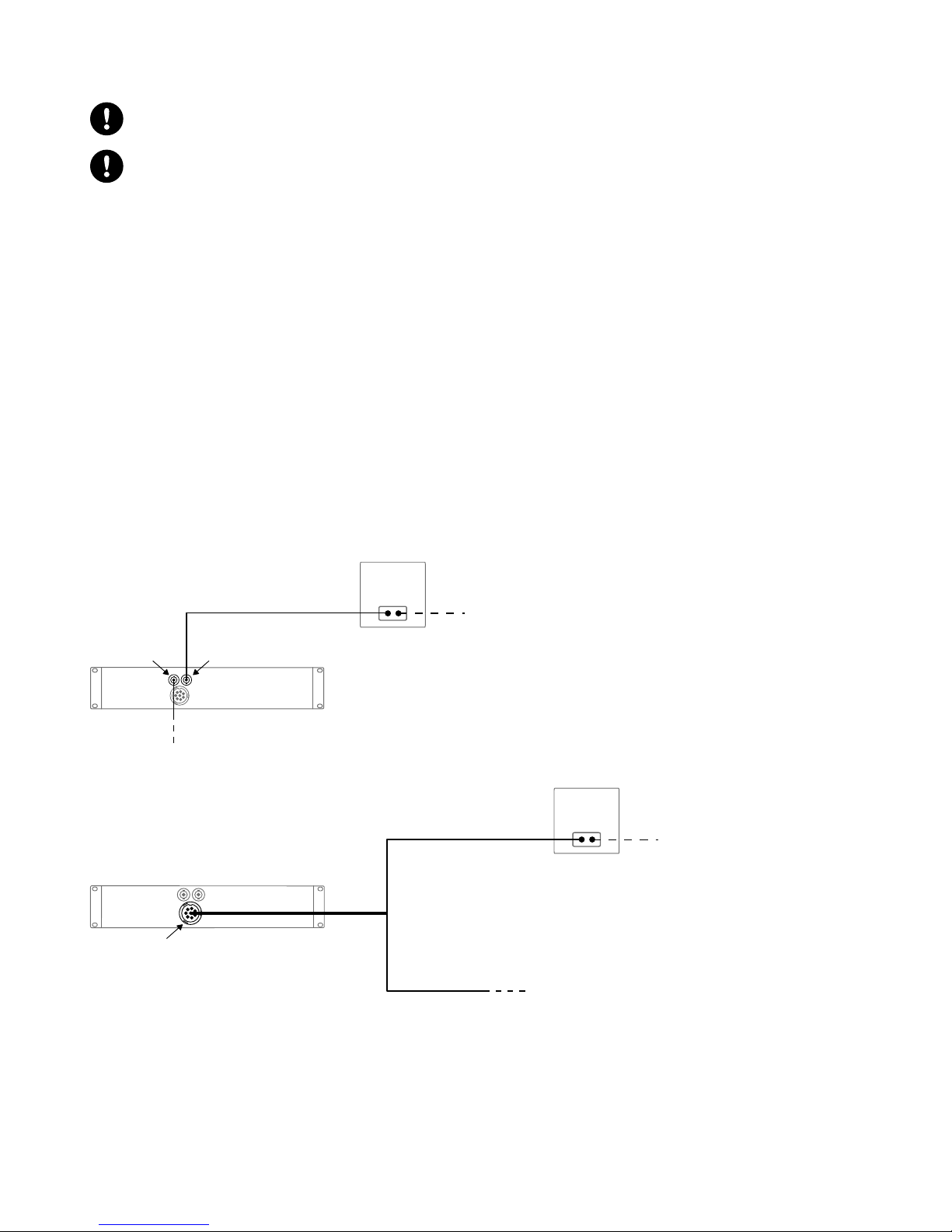
Analog audio
Balanced cables
Symmetrical (balanced) shielded cables are highly recommended as balanced signals are less sensitive to AC
hum and radio interference.
Unbalanced lines may add noise especially over long cable runs.
In a daisy-chain layout, the male XLR link connectors LINK A to LINK D feed the input signals to the next amplied
controller in the signal chain.
daisy-chaining analog audio
IN A
IN C
IN B
IN D
LINK A LINK B
Analog daisy-chain and LA4/LA8 with power off or in standby
In an analog daisy-chain, LA4 and LA8 with power off or in standby cause sound distortion at high input levels to
the other amplied controllers they are connected to.
Make sure all Units are powered on and in operating (not in standby) mode, or disconnect them from the daisychain.
LA12X user manual (EN) version 4.0 21
Installation
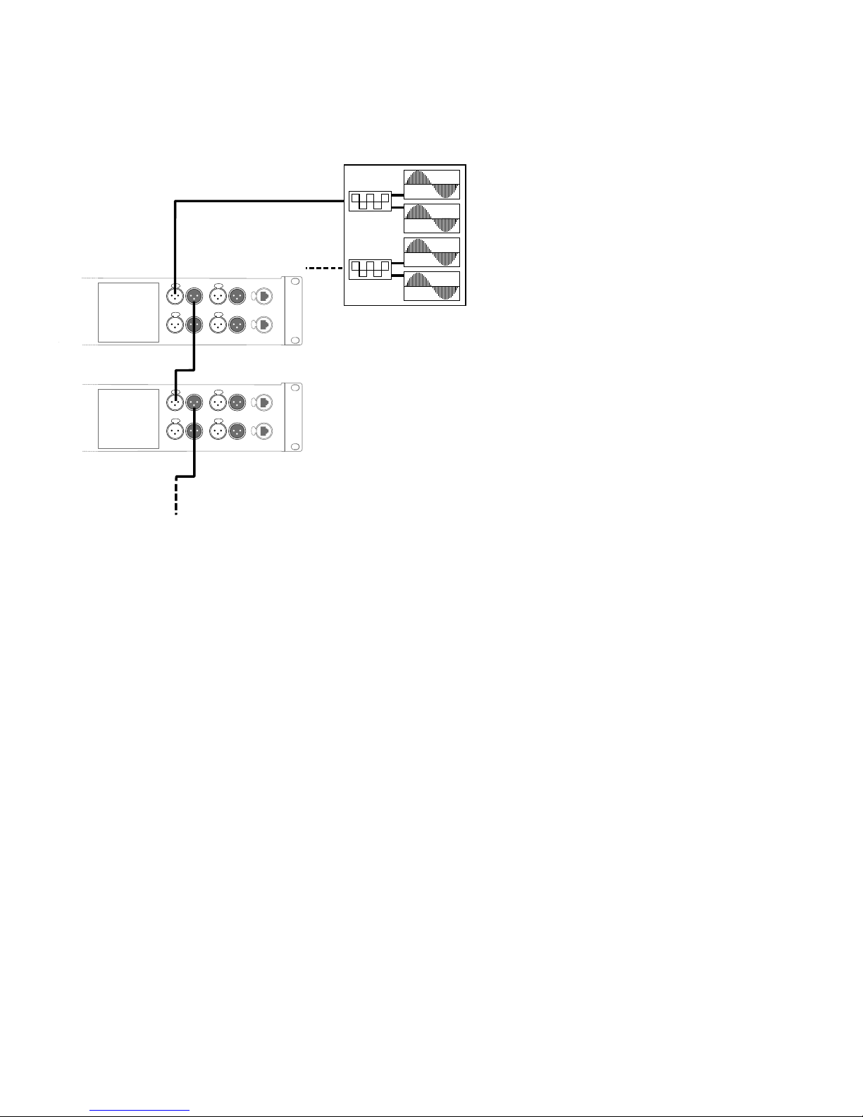
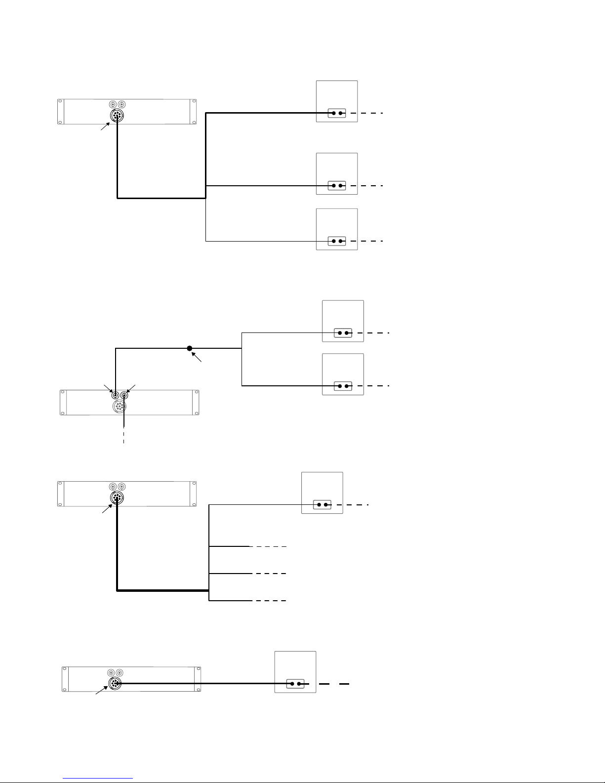
Digital audio
In a daisy-chain layout, the male XLR link connectors LINK A&B and LINK C&D feed the input signals to the next amplied
controller in the signal chain.
daisy-chaining digital audio
IN A&B
IN C&D
LINK A&B
Cables for AES/EBU digital audio
AES3 species that the nominal characteristic impedance of cables used for AES/EBU digital audio transmission shall
be 110 Ω ± 20%, and closer tolerances allow for increased transmission reliability over long lengths or higher sampling
rates.
Therefore, it is highly recommended to use high-quality AES/EBU rated cables only, although certain cables designed for
balanced analog audio prove to be acceptable at 48 kHz sampling rate over very short distances.
It is recommended to use single lengths of cable between AES/EBU outputs and inputs. Using several shorter cables
joined together reduces performance. If it is not possible to use single lengths, it is required to use the same model of
cable between two AES/EBU interfaces.
In case an amplied controller shuts down, the failsafe relay makes a passive connection between the AES/EBU IN ports
and the LINK ports to maintain continuity. However the signals are no longer refreshed for the next amplied controller,
so that the input cable and the link cable must be considered as a unique input cable with regard to the maximum
supported length.
In case of transmission losses, try to reduce the sampling frequency of the digital audio source. Moreover, as a general
rule, avoid using sources rated beyond 96 kHz, as the maximum possible cable length is reduced, while the additional
information is cancelled by SRC to 96 kHz.
22 LA12X user manual (EN) version 4.0
Installation
L-NET
Do not create loops in the network setup
LA4X and LA12X amplied controllers should always be placed before LA4 and LA8 amplied
controllers in daisy-chain networks.
LA4 and LA8 amplied controllers are equipped with former generation 100 Mb/s Ethernet ports that cannot
communicate with Ethernet ports of different capabilities, creating detection issues in LA Network Manager.
To connect LA12X to L-NET in a daisy-chain, star or hybrid topology, use the etherCON connectors on the L-NET panel.
Refer to the LA Network Manager Help for network setup.
AVB
To connect LA12X to an AVB network or use LA12X to create an AVB network, use the etherCON connectors on the rear
panel.
Refer to the LA Network Manager Help for more information on how to connect LA12X to the AVB network in daisychain, star or hybrid topologies.
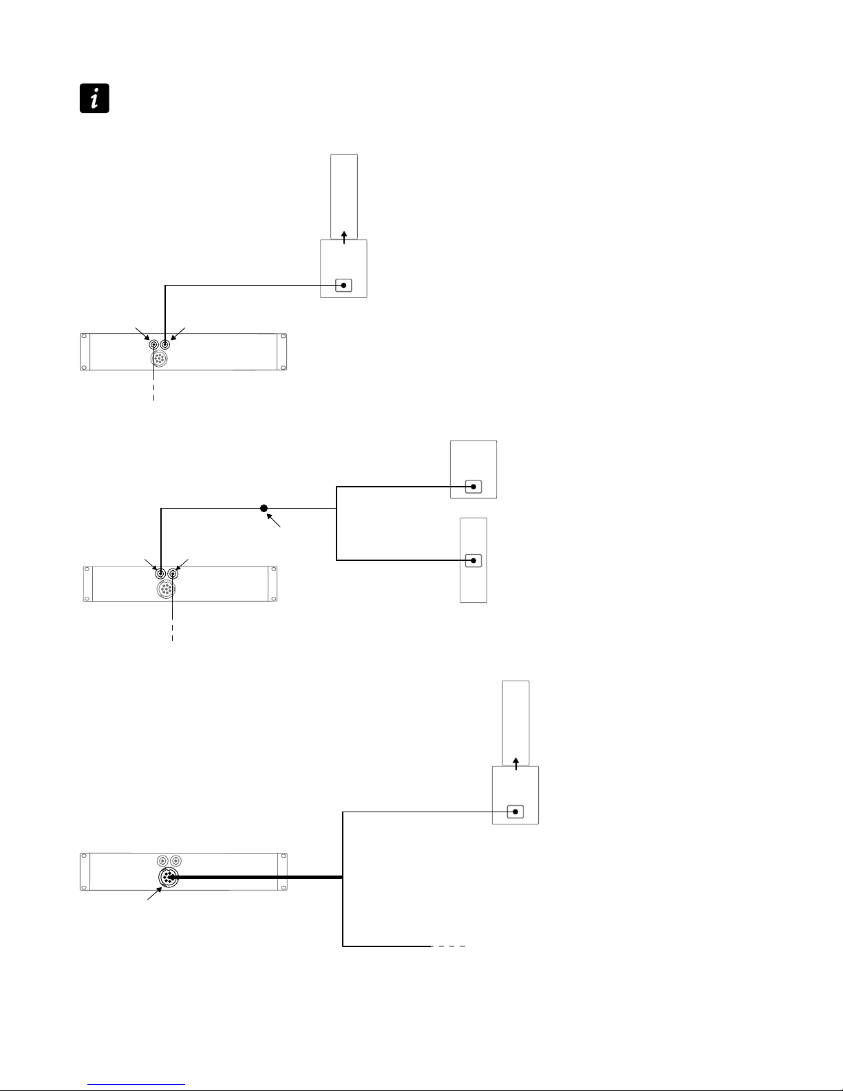
Speaker
To connect an enclosure to the amplied controller, use the speakON or the 8-point output connectors.
Connecting 2-way active enclosures
SP on speakON output
SP
OUT1/OUT2 OUT3/OUT4
same as OUT1/OUT2
SP
DO and DOFILL-LA8 on CA-COM output
CA-COM
DO
DOFILL-LA8
SP
2W CH(A) (OUT1/OUT2)
2W CH(B) (OUT3/OUT4)
LA12X user manual (EN) version 4.0 23
Installation
Connecting a 2-way active enclosure with subwoofers
DO and DO3WFILL on CA-COM output
CA-COM
DO
DO3WFILL
2WAY (OUT3/4)
SUB1 (OUT1)
SUB2 (OUT2)
SP
SP
SP
Connecting 2-way passive enclosures or subwoofers
SP and SP-Y1 on speakON output
OUT1/OUT2
OUT3/OUT4
same as OUT1/OUT2
SP SP-Y1
CC4FP
CH(1) (OUT1)
CH(2) (OUT2)
SP
SP
DO and DOSUB-LA8 on CA-COM output
CA-COM
DO
DOSUB-LA8
SPK1 (OUT1)
SPK2 (OUT2)
SPK3 (OUT3)
SPK4 (OUT4)
SP
Connecting 3-way active enclosures
DO on CA-COM output
CA-COM
DO
DO
24 LA12X user manual (EN) version 4.0
Installation
Connecting hybrid congurations
Refer to the Syva user manual for more information.
SP on speakON output
Autoconnect
SP
OUT1/OUT2 OUT3/OUT4
same as OUT1/OUT2
SP and SP-Y1 on speakON output
OUT1/OUT2
OUT3/OUT4
same as OUT1/OUT2
SP SP-Y1
CC4FP
CH(1) (OUT1)
CH(2) (OUT2)
DO and DOFILL-LA8 on CA-COM output
Autoconnect
CA-COM
DO
DOFILL-LA8
2W CH(A) (OUT1/OUT2)
2W CH(B) (OUT3/OUT4)
LA12X user manual (EN) version 4.0 25
 Loading...