

L-Acoustics dV-DOSC, dV-SUB Operator's Manual

Version 2.0
November 2001
dV-DOSC
dV-SUB
OPERATOR MANUAL


dV-DOSC dV-SUB Manual V2.0 Nov 2001
3
FOREWORD
This manual is intended for sound engineers who are responsible for the set-up, operation and
maintenance of L-ACOUSTICS
®
dV-DOSC™ systems. It is also intended to provide interested sound
designers, consultants and installers with the information they require regarding the fundamental
principles of Wavefront Sculpture Technology
®
and how these principles are embodied within the
dV-DOSC sound reinforcement system. dV-DOSC specifications, installation procedures and general
guidelines for sound design are also discussed in this document.
MANUAL ORGANIZATION
The Introduction gives a brief presentation of the dV-DOSC system and presents the
fundamentals of Wavefront Sculpture Technology
Chapter 1 introduces the elements of the dV-DOSC system.
Chapter 2 describes dV-DOSC array performance and coverage prediction.
Chapter 3 discusses elements of sound design and suggested array configurations.
Chapter 4 gives detailed procedures for stacking and flying dV-DOSC.
Chapter 5 lists recommended installation and maintenance tools.
Chapter 6 gives specifications for elements of the dV-DOSC system.
Finally, the Appendices elaborate on several technical aspects.

dV-DOSC dV-SUB Manual V2.0 Nov 2001
4
TABLE OF CONTENTS
0. INTRODUCTION...............................................................................................................................................8
0.1 WAVEFRONT SCULPTURE TECHNOLOGY™ FUNDAMENTALS .......................................................................8
The Sound Reinforcement Problem ................................................................................................................8
Wavefront Sculpture Principles........................................................................................................................9
First V-DOSC, Now dV-DOSC .....................................................................................................................10
Summary of dV-DOSC Applications ..............................................................................................................14
0.2 TRAINING AND QUALIFICATIONS .................................................................................................................15
THE QUALIFIED V-DOSC TECHNICIAN (QVT) .......................................................................................15
THE CERTIFIED V-DOSC ENGINEER (CVE) ..............................................................................................15
1. ELEMENTS OF THE dV-DOSC SYSTEM.....................................................................................................16
1.1 dV-DOSC SYSTEM COMPONENTS .................................................................................................................19
1.2 dV-DOSC ENCLOSURE DESCRIPTION ............................................................................................................23
1.3 dV-DOSC FLYING SYSTEM .............................................................................................................................23
1.4 dV-DOSC AMPLIFIER RACKS........................................................................................................................... 26
1.5 POWERING dV-DOSC ....................................................................................................................................31
1.6 dV-SUB ENCLOSURE DESCRIPTION...............................................................................................................34
1.7 dV-SUB FLYING SYSTEM................................................................................................................................35
1.8 POWERING dV-SUB.......................................................................................................................................37
1.9 dV-DOSC CONTROL.......................................................................................................................................38
(a) General Guidelines Regarding System Protection....................................................................................38
(b) Preset Policy .............................................................................................................................................38
(c) General Description of dV-DOSC Presets...............................................................................................39
(d) BSS FDS 355 VERSION 6 0801 PRESETS.................................................................................................41
(e) BSS FDS 366 VERSION 6 0801 PRESETS.................................................................................................42
(f) XTA DP224 VERSION 6 0801 PRESETS...................................................................................................43
(g) XTA DP226 VERSION 6 0801 PRESETS..................................................................................................44
1.7 CONTROL SIGNAL DISTRIBUTION.................................................................................................................45
1.8 CO 24 CONTROL OUTPUT PANEL..................................................................................................................46
1.9 MD 24 MULTI DISTRO PANEL........................................................................................................................47
1.10 CD12 CONTROL DISTRO PANEL ..................................................................................................................48
2. dV-DOSC ARRAY SPECIFICATIONS...........................................................................................................51
2.1 ISOCONTOUR IN THE HORIZONTAL PLANE.................................................................................................51
Horizontal Directivity of a dV-DOSC Array..................................................................................................51
Effective Coverage in the Horizontal Plane...................................................................................................51
2.2 WAVEFRONT SCULPTURE IN THE VERTICAL PLANE......................................................................................52
Flat dV-DOSC Array ......................................................................................................................................52
Convex Curvature dV-DOSC Array .............................................................................................................52
Constant Curvature dV-DOSC Array ...........................................................................................................52
Variable Curvature dV-DOSC Array .............................................................................................................53
Concave Curvature dV-DOSC Array............................................................................................................53
2.3 COVERAGE PREDICTIONS USING THE ARRAY 2000 SPREADSHEET ..............................................................53
CUTVIEW SHEETS (ARRAY1, ARRAY2, dV-ARRAY1, dV-ARRAY2)...........................................................................54
a) Input Data...................................................................................................................................................54
b) Optimization Procedure ............................................................................................................................56
c) Output Data ...............................................................................................................................................56

dV-DOSC dV-SUB Manual V2.0 Nov 2001
5
SIMULATING dV-DOSC DOWNFILL ..........................................................................................................58
SIMULATING dV-DOSC UPFILL ..................................................................................................................58
dV-DOSC PICK POINT UTILITY..................................................................................................................59
H-ISOCONTOUR SHEET......................................................................................................................................59
a) Input Data...................................................................................................................................................59
b) Optimization Procedure ............................................................................................................................60
c) Output Data ...............................................................................................................................................60
ARRAY 2000 SPREADSHEET CALCULATION EXAMPLES........................................................................................61
3. ELEMENTS OF SOUND DESIGN..................................................................................................................63
3.1 MULTIPLE ARRAY CONCEPTS .........................................................................................................................63
Reducing Array Interaction ............................................................................................................................63
Achieving Optimum Coverage.......................................................................................................................63
3.2 STACKED OR FLOWN?...................................................................................................................................64
Stacking Guidelines.........................................................................................................................................64
Flying Guidelines.............................................................................................................................................65
3.3 SUBWOOFERS...............................................................................................................................................66
General Guidelines for the Use of Subwoofers.............................................................................................66
Split Left/Right Ground Stacked Subwoofers .................................................................................................66
Flown Subwoofers .........................................................................................................................................67
Central Location, Ground Stacked.................................................................................................................68
3-WAY PRESETS FOR dV-DOSC AND SB218 SUBWOOFERS................................................................................68
3-WAY PRESETS FOR dV-DOSC AND dV-SUB SUBWOOFERS..............................................................................68
4-WAY PRESETS FOR dV-DOSC AND dV-SUB OR SB218 SUBWOOFERS .............................................................70
4. INSTALLATION PROCEDURES ...................................................................................................................71
4.1 STACKED SYSTEMS........................................................................................................................................71
Stacking dV-DOSC Standalone ......................................................................................................................71
Safety Rules.....................................................................................................................................................72
Stacking on top of V-DOSC ...........................................................................................................................77
Stacking on top of SB218 Subwoofers ...........................................................................................................80
Stacking dV-SUB Subwoofers ........................................................................................................................84
Stacking dV-DOSC on top of dV-SUBS .........................................................................................................87
Procedure 1: Stacking without dV-BUMP .....................................................................................................87
Procedure 2: Stacking with dV-BUMP...........................................................................................................90
4.2 FLOWN SYSTEMS..........................................................................................................................................92
Standalone Flying with dV-BUMP ..................................................................................................................92
Trim and Angle Adjustments..........................................................................................................................99
Flying under V-DOSC with dV-DOWN ......................................................................................................101
Flying dV-SUB Standalone ............................................................................................................................105
Flying dV-DOSC Under dV-SUB (3+1 configuration) ................................................................................108
Flying dV-DOSC Under dV-SUB (larger configurations).............................................................................112
Procedure 1 (2 dV-SUB + 6 dV-DOSC).....................................................................................................112
Procedure 2 (larger configurations).............................................................................................................113
SAFETY RULES ...................................................................................................................................................119
5. MAINTENANCE AND INSTALLATION TOOLS .....................................................................................121
5.1 RECOMMENDED MAINTENANCE PROCEDURES.........................................................................................121
5.2 RECOMMENDED MAINTENANCE TOOLS....................................................................................................121
5.3 SPARE PARTS................................................................................................................................................122
5.4 RECOMMENDED INSTALLATION TOOLS.....................................................................................................123

dV-DOSC dV-SUB Manual V2.0 Nov 2001
6
6. SPECIFICATIONS ..........................................................................................................................................124
6.1 dV-DOSC ELEMENT SPECIFICATIONS..........................................................................................................124
6.2 dV-SUB SPECIFICATIONS .............................................................................................................................127
APPENDIX 1: How Does dV-DOSC Behave With Respect To WST Criteria ........................................129
APPENDIX 2: How Does the DOSC Waveguide Work?.............................................................................130
LIST OF FIGURES
Figure 1: Wavefield interference for a conventional system compared to a sculptured dV-DOSC
wavefield ............................................................................................................................... 9
Figure 2: Wavefront Sculpture Technology Criteria ...................................................................... 10
Figure 3a: System Block Diagram.................................................................................................17
Figure 3b: Example System Configuration..................................................................................... 18
Figure 4: dV-DOSC and Accessories ............................................................................................ 22
Figure 5: dV-DOSC Element - Front and Rear Views .................................................................... 23
Figure 6: dV-ANGLE P1 and P2 angle values ................................................................................ 24
Figure 7: dV-BUMP..................................................................................................................... 25
Figure 8: dV-DOWN................................................................................................................... 25
Figure 9: V-DOSC AMP RACK RK12-4......................................................................................... 26
Figure 10: PAD 04 (4 amplifiers per rack)..................................................................................... 27
Figure 11: RK12-2M and RK12-2S Master and Slave Racks............................................................. 29
Figure 12: PAD 02 (2 amplifiers per rack)..................................................................................... 29
Figure 13: Connecting dV-DOSC to L-ACOUSTICS RK12-4.......................................................... 33
Figure 14: dV-SUB....................................................................................................................... 34
Figure 15: dV-ANGLESS sub-to-sub angle bar............................................................................... 35
Figure 16: dV-ANGLESDP and dVANGLESD hole definitions........................................................ 35
Figure 17: Illustration of dV-SUB rigging configurations................................................................. 37
Figure 18: CO24 Control Output Panel ....................................................................................... 46
Figure 19: MD24 Multi Distro Panel............................................................................................. 47
Figure 20: CD 12 Control Distro Panel ........................................................................................ 48
Figure 21: System Architecture using RK12-2M Master Rack and RK12-4....................................... 50
Figure 22: Defining Cutview Dimensions...................................................................................... 54
Figure 23: Parameters for the ROOM DIM Utility Sheet in ARRAY ............................................... 55
Figure 24: Optimizing Array Element Focus By Adjusting For Equal Spacing .................................. 56
Figure 25: Physical dV-DOSC Rigging Parameters for ARRAY........................................................ 57
Figure 26a: ARRAY 2000 spreadsheet calculation example (LCR dV-DOSC system) ....................... 61
Figure 26b: Simulating dV-DOSC under V-DOSC ......................................................................... 62
Figure 26c: Simulating dV-DOSC on top of V-DOSC .................................................................... 62
Figure 27: Recommended Installation Tools ................................................................................123
Figure 28: dV-DOSC Element – Line Drawing.............................................................................125
Figure 28: dV-SUB Line Drawing.................................................................................................127
Figure 30: Front view of dV-DOSC array and vertically stacked DOSC waveguides......................129
Figure 31: DOSC Waveguide – Internal Section...........................................................................130
LIST OF TABLES
Table 1: PAD04 Amp Panel Wiring Chart..................................................................................... 28
Table 2: PAD02 Amp Panel Wiring Chart..................................................................................... 30

dV-DOSC dV-SUB Manual V2.0 Nov 2001
7
Table 3: Power Handling versus HP Filter Characteristics for dV-DOSC LF................................... 31
Table 4: Load, RMS and Peak Power Ratings for dV-DOSC........................................................... 31
Table 5: Recommended Amplifier Power Ratings for 100 Hz LR24 HPF......................................... 32
Table 6: L-ACOUSTICS LA 24 MLS Settings for use with dV-DOSC.............................................. 32
Table 7: L-ACOUSTICS LA 48 MLS Settings for use with dV-DOSC.............................................. 32
Tables 8, 9: Maximum rated dV-SUB / dV-DOSC combinations..................................................... 36
Table 10: Recommended Power and Amplifier Power Ratings for dV-SUB..................................... 37
Table 11: BSS FDS 355 Presets .................................................................................................... 41
Table 12: BSS FDS 366 Presets .................................................................................................... 42
Table 13 : XTA DP224 Presets .................................................................................................... 43
Table 14: XTA DP226 Presets ..................................................................................................... 44
Table 15: Pick Point Reference Chart (1 dV-SUB + 3 dV-DOSC).................................................109
Table 16: Recommended Maintenance Tools ..............................................................................121
Table 17: dV-DOSC weight per number of cabinets.....................................................................126

dV-DOSC dV-SUB Manual V2.0 Nov 2001
8
0. INTRODUCTION
The small ''d'' in dV-DOSC refers to the mathematical terminology for the derivative function since
dV-DOSC is a derivative of V-DOSC. dV-DOSC provides the same benefits of Wavefront Sculpture
Technology as V-DOSC except in a much smaller format.
We hope this manual will help you to appreciate why and to understand the basic principles behind
how the dV-DOSC system works. Understanding these principles will help you to optimally use dVDOSC and dV-SUB in sound design – whether for touring or fixed installation. Understanding the
concepts behind dV-DOSC and Wavefront Sculpture Technology are just as important as learning
the many operational details related in this manual – the more you understand the big picture, the
more effectively you will use the system.
As you will see, dV-DOSC is a complete system approach – starting from the basic question of how
to effectively couple sound sources then including all aspects of sound design, performance
prediction, system installation, rigging, cabling, signal distribution, digital control and tuning. This
turnkey system approach allows for accurate and predictable results, however, in order to achieve
the best results you need to understand the concepts behind how the system works.
Apart from sound quality, the system design approach and ergonomics, there are many benefits to
dV-DOSC. Many of you readers are already aware of these benefits; otherwise they will become
apparent throughout the course of this manual.
0.1 WAVEFRONT SCULPTURE TECHNOLOGY™ FUNDAMENTALS
The Sound Reinforcement Problem
The trend in sound reinforcement has been to increase both the actual SPL during concerts and the
size of the audience to be covered. This leads to an increased number of loudspeakers since more
powerful single loudspeakers would reach such sizes and weights that their transport, handling and
installation would simply not be feasible.
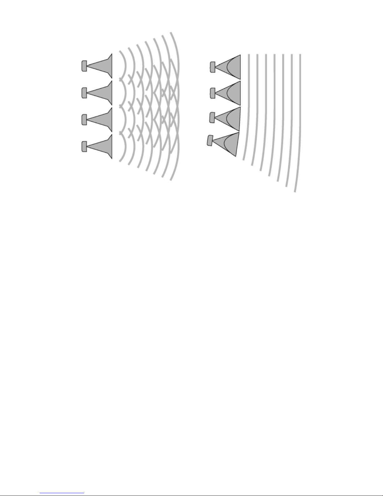
In practice, conventional loudspeakers are assembled in a fan-shaped array following the angle
determined by the horizontal directivity of each enclosure in an attempt to reduce overlapping
zones that cause destructive interference. With this type of arrangement, the optimum clarity
available in one direction can only be provided by the individual enclosure facing in this direction.
Attempts at “flattening the array” in order to achieve greater throw and higher sound pressure levels
results in severe interference in an uncontrolled way, affecting coverage, directivity control,
intelligibility and overall sound quality. Even when arrayed according to specification (always an
''optimum'' compromise), the sound waves radiated by individual loudspeakers do not couple
coherently thus the conventional system approach is fundamentally flawed. Furthermore, the chaotic
sound fields created by interfering sound sources waste acoustic energy, thus requiring more power
than a single, coherent source would in order to achieve the same sound pressure level.
To illustrate this, consider what happens when we throw pebbles in the water. If we throw one
pebble into the water, we can see circular waves expanding from the place where it disturbed the
surface. If we throw a handful of pebbles, we observe a chaotic wavefield. If we throw a larger
stone, with total size and weight equivalent to the handful of pebbles then we see a circular wave as
was obtained with the single pebble, except now with much larger amplitude. If all of the individual
pebbles of the handful could be glued together, this would provide the same effect as the larger
stone...
This illustrates the thinking behind dV-DOSC and V-DOSC: if we can build a single sound source
from a number of individual speakers that can be separated for transport and handling, then we have
achieved our goal, i.e., to provide a totally coherent, predictable wavefield.
dV-DOSC dV-SUB Manual V2.0 Nov 2001
9
Figure 1: Wavefield interference for a conventional sound reinforcement system
compared to a sculptured dV-DOSC wavefield
Wavefront Sculpture Principles
As early as 1988, a preliminary system named "Incremental" had proven the feasibility of V-DOSC
and dV-DOSC. From this experimental concept, theoretical research was undertaken by Professor
Marcel Urban and Dr. Christian Heil. The results of this research were presented at the 92nd AES
convention in Vienna, March 1992 (preprint n°3269).
The theory that was developed defines the acoustic coupling conditions required for effectively
arraying individual sound sources. Relevant parameters include: wavelength, the shape of each
source, the surface area of each source and the relative source separation.
In brief, the coupling conditions can be summarized as follows:
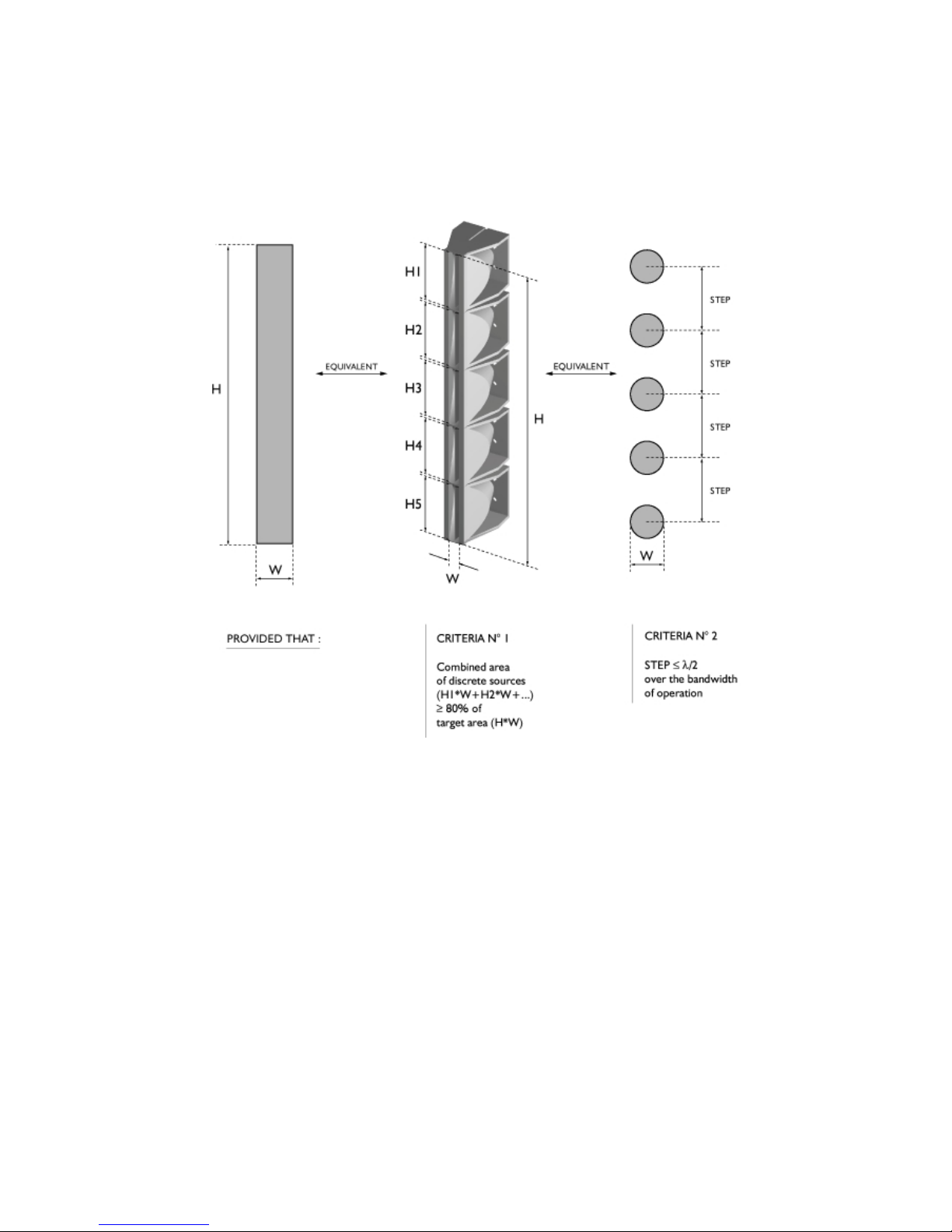
An assembly of individual sound sources arrayed with regular separation between the sources on a plane or
curved continuous surface is equivalent to a single sound source having the same dimensions as the total
assembly if one of the two following conditions is fulfilled:
1) Shape: The wavefronts generated by the individual sources are planar and the combined surface area of
the sources fills at least 80% of the total target surface area.
2) Frequency: The step or source separation, defined as the distance between the acoustic centers of the
individual sources, is smaller than half the wavelength over the bandwidth of operation.
These two criteria form the basis of Wavefront Sculpture Technology™ (referred to as WST
throughout this text). For further information, more detailed theory is presented in Appendix 3.
Additional WST Criteria were developed for the AES preprint entitled ''Wavefront Sculpture
Technology'' that was prepared for the 111
th
Convention, NYC, Sept 2001 (preprint n°5488). The
first two WST Criteria were re-derived based on an intuitive approach using Fresnel analysis and in
addition it was shown that:
3) The deviation from a flat wavefront must be less than
λ
/4 at the highest operating frequency (this
corresponds to less than 5 mm curvature at 16 kHz)
dV-DOSC dV-SUB Manual V2.0 Nov 2001
10
4) For curved arrays, enclosure tilt angles should vary in inverse proportion to the listener distance
(geometrically this is equivalent to shaping variable curvature arrays to provide equal spacing of individual
element impact zones)
5) Limits exist given the vertical size of each enclosure and the relative tilt angles that are allowed between
enclosures.
Figure 2: Wavefront Sculpture Technology Criteria
First V-DOSC, Now dV-DOSC
V-DOSC is the first system that functions according to the principles of Wavefront Sculpture
Technology. DOSC stands for ”Diffuseur d’Onde Sonore Cylindrique” – in english this means
Cylindrical Sound Wave Generator. The “V” in V-DOSC refers to the V-shaped acoustic lens
configuration employed for the mid and high frequency sections. As stated above, dV-DOSC can be
considered a derivative of V-DOSC since it performs according to the same principles except in a
smaller format.
An important design objective for dV-DOSC was to provide expanded horizontal and vertical
coverage and this has been achieved in two ways - first, the V-shaped acoustic lens section for the
low section (that also acts as a waveguide for the high section) has been engineered to provide 120
degree horizontal coverage in comparison with the 90 degree coverage of V-DOSC. Secondly, the
innovative construction of dV-DOSC employs minimum thickness top and bottom aluminum plates
and the rigging system pivots around the front points of the enclosures - these two features bring the
openings of the individual DOSC waveguides (one per enclosure) as close together as possible,
allowing dV-DOSC to be used up to a maximum of 7.5 degrees between each enclosure while still
satisfying the greater than 80% fill WST criterion. By comparison, V-DOSC enclosures can be
arrayed up to a maximum of 5 degrees between elements.

dV-DOSC dV-SUB Manual V2.0 Nov 2001
11
dV-DOSC enclosure trapezoidal angles have been engineered so that 7.5 degrees per enclosure is
obtained for tightly wrapped arrays. Starting from a tightly wrapped array (7.5 degrees between
cabinets) the backs of the dV-DOSC enclosures can be progressively opened up using dV-ANGLEP1
or dV-ANGLEP2 rear angle bars by selecting various hole positions to produce variable curvature
arrays. A flat array is obtained using the maximum extension hole position on dV-ANGLEP1 for all
enclosures. Array curvature obtained using dV-ANGLEP is described as convex and the array shape
corresponds to the positive curvature that we are familiar with.
If dV-ANGLEN rear angle bars are selected, concave or negative curvature arrays can be
constructed (to visualize a negative curvature array, just think of a satellite dish). A flat array is
obtained using the minimum hole position on dV-ANGLEN and the array becomes progressively
concave as hole positions with greater spacing are selected. Experimentation into the use of negative
curvature arrays is ongoing and it is thought that such arrays will be highly useful for longthrow
applications and for acoustic holography effects where it is possible to create a virtual acoustic
source by focussing sound at a defined location in space. The sound will then appear to emanate
from a focal line - not from the array itself - allowing for interesting sound design possibilities.
Alternatively, dV-ANGLEN can be used to provide negative tilt for a dV-DOSC array when dVDOSC is stacked on top of subwoofers.
Just as for V-DOSC, dV-DOSC was designed as a system consisting of identical, vertically-arrayable
elements. Individual transducers are physically arranged within each enclosure so as to meet WST
criteria, frequency-band by frequency-band, when the enclosures are arrayed together. Each
element radiates a flat isophasic (constant phase) wavefront, allowing the overall assembly of
multiple elements to produce a single extended sound source. Since the angle of separation between
adjacent elements is adjustable, the wavefront can be shaped by physically shaping the array.
Through successful coupling over the entire audio frequency range, dV-DOSC produces a consistent
wavefront over a large area with little variation in frequency response and sound pressure level.
The heart of the dV-DOSC system is the internationally patented
1
DOSC waveguide. Essentially, the
DOSC waveguide permits fulfilment of the first condition of WST for frequencies higher than
800 Hz, i.e., the wavefronts generated by individual DOSC waveguides are planar and their
combined surface area accounts for at least 80% of the total surface area. For conventional hornloaded systems, coherent summation is simply not possible at higher frequencies since the
wavelength becomes progressively smaller than the physical separation between horn and driver
assemblies and neither of the two WST criteria can be satisfied. As a result, interference occurs
throughout most of the high frequency section's operating bandwidth for a conventional system.
By comparison, a dV-DOSC array is a full-spectrum, coherent loudspeaker system even for the
highest frequencies. As with any speaker system, interference does occur for the case of dV-DOSC,
however, the main difference is that within the defined coverage region the interference is
constructive, while outside of the defined wavefield it is destructive.
dV-DOSC elements are vertically arrayed in columns. Since elements of the array couple coherently,
the enclosures are physically smaller and fewer cabinets are required in comparison with
conventional systems. This makes dV-DOSC very cost effective for touring sound applications where
transport space and handling time means money. These properties also make dV-DOSC highly
effective for fixed installation where compact size combined with predictable coverage is important.
One of the key benefits of WST is the predictability of the wavefront's shape. Horizontally, the
entire dV-DOSC array has the same directivity as a single element (120°). Vertically, the coverage is
determined by the number of vertically arrayed elements and the specified angle of separation
between them. Given this predictability, vertical coverage can be optimized to match specific
audience area geometries. A quick, user-friendly CAD spreadsheet helps the operator to determine
how to focus the wavefield so that tonal balance and sound pressure levels are evenly distributed
throughout the listening area. Using this program, array design can be conveniently performed on a
case-by-case basis to optimize coverage for each venue according to the specific audience layout.
1
The DOSC waveguide is registered under European patent n°0331566 and North American patent n°5163167. Please see Appendix
2 for a description of the DOSC waveguide.
dV-DOSC dV-SUB Manual V2.0 Nov 2001
12
The configuration of transducers in a dV-DOSC element is symmetrical with respect to the plane of
propagation of the wave, i.e., the plane bisecting the horizontal coverage angle. High frequency
transducers are located in the middle and low frequency transducers are located on both sides of the
high section. Such a configuration is described as having COPLANAR SYMMETRY.
Coplanar symmetry is the cylindrical domain equivalent of the coaxial arrangement for individual
(spherical) sources. Essentially, coplanar symmetry allows for homogeneous coverage of the sound
field at any listening angle over the dV-DOSC array’s 120° horizontal coverage window. Coplanar
symmetry also eliminates off-axis acoustic cancellations at crossover points so that polar lobing is not
an issue. Psychoacoustically, coplanar symmetry is largely responsible for the exceptional imaging
properties that are characteristic of dV-DOSC when used in stereo (Left / Right) configurations.
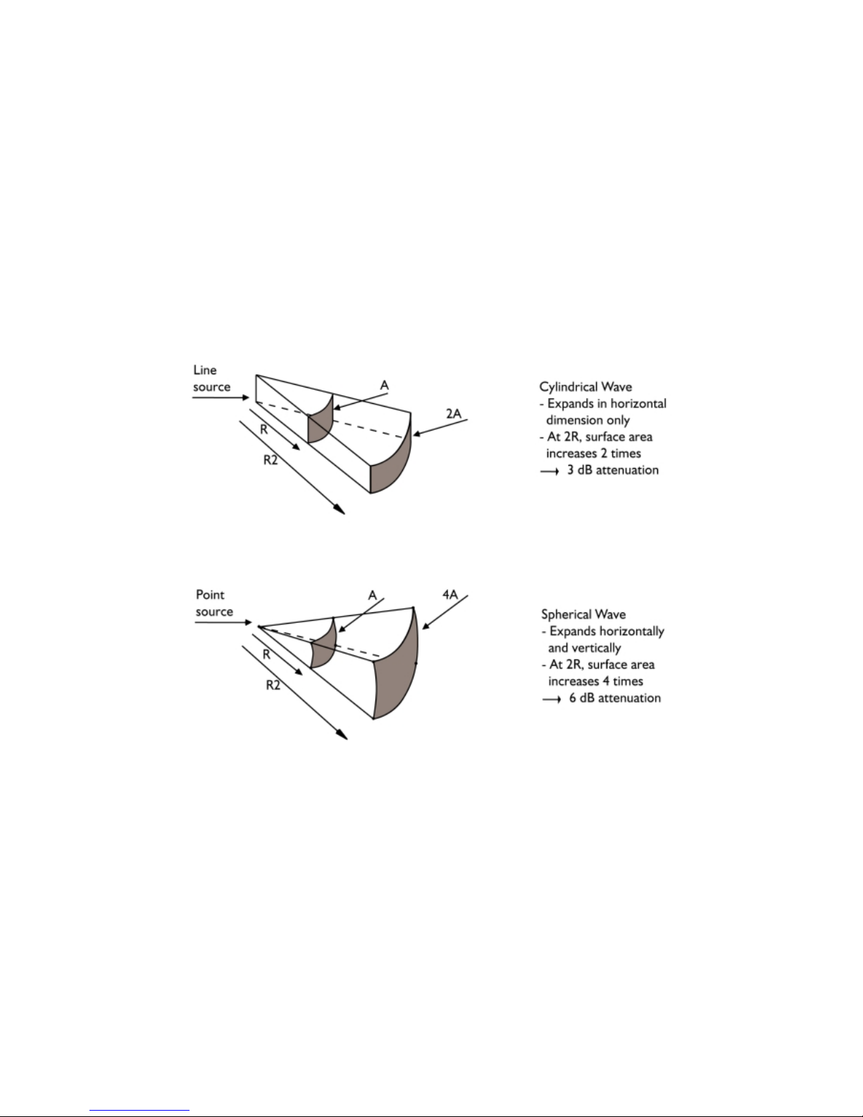
Apart from coverage precision and predictability, another significant benefit of dV-DOSC is the fact
that the system effectively extends the near field region at higher frequencies. For flat dV-DOSC
arrays, this results in a 3 dB reduction in SPL with doubling of distance as opposed to the 6 dB
reduction that is typical of conventional systems. This property arises due to the physics of cylindrical
waves versus spherical waves (see the figure below).
This means that dV-DOSC should not be evaluated in terms of the classical "$ / kilowatt"-ratio, i.e.,
due to it’s ability to perform Wavefront Sculpture, dV-DOSC has different attenuation properties
than conventional systems. Comparing SPL predictions according to standard calculations is not
meaningful since dV-DOSC produces a combination of cylindrical and spherical wavefront
propagation that must be evaluated using specific calculations.
Aside: This is one of the reasons why EASE and CATT-Acoustic modelling data was not available for dVDOSC, V-DOSC and ARCS in the past (whereas data was provided for the coaxial MTD products
manufactured by L-ACOUSTICS). Custom modelling for WST-based system simulation has recently been
completed for the EASE and CATT-Acoustic room acoustics modelling packages.
When curved dV-DOSC arrays are employed there is a combination of cylindrical and spherical
propagation. This combined propagation, together with the actual shape of the audience geometry
allows the wavefield to be focused so that tonal balance and sound pressure levels are evenly
distributed throughout the listening area. Although pure cylindrical wave propagation is not always in
effect, 3 dB reduction with distance can still be obtained along with extension of the nearfield by

dV-DOSC dV-SUB Manual V2.0 Nov 2001
13
correctly focussing the system on the audience - this is the benefit of WST and also the reason why
correct focus of the system on the audience area is so important.
Psychoacoustically, nearfield extension allows one to walk a considerable distance from a dV-DOSC
system with only a small difference in SPL due to the system’s unconventional attenuation rate.
Effectively, more of the audience experiences nearfield listening, enjoying higher fidelity, improved
stereo imaging and exceptional clarity. Subjectively, the loudspeakers seem much closer and the
sound is ''in your face''. Image localization is towards the action on stage - not the loudspeaker
arrays. Practically, this extension of the nearfield means that extreme sound pressure levels are not
required close to the system in order to provide acceptable SPLs further back in the audience - this
is a highly desirable property that results in reduced potential for hearing loss for both audiences and
engineers.
Nearfield extension, combined with the precision and predictability of dV-DOSC coverage is also
effective in “pushing back” the critical distance in highly reverberant spaces (critical distance is
defined as the distance where the energy of the direct sound is equal to the reverberant energy). In
many situations, it is extremely important to keep energy off the roof, for example in arenas or
outdoor amphitheatres. If we can excite less room reverberation and focus more energy on the
audience, we can effectively move back the critical distance in a given room. Given the well-defined
vertical coverage of dV-DOSC, the benefits of WST become immediately obvious in comparison
with conventional systems when working in difficult rooms.
Finally, another benefit of WST is the high degree of SPL rejection that is obtained outside of the
defined wavefield. Nominally as high as 20 dB, this permits the installation of a dV-DOSC array
behind or above microphones with exceptionally high feedback immunity. Basically, if you can see
the bottom of the bottom enclosure of the array, you are outside of the coverage pattern (actually,
you are 3.75 degrees outside the coverage pattern – more on this later!). Monitor engineers also
enjoy working with dV-DOSC FOH systems since there is very little backwave on stage - even at
lower frequencies due to the coplanar symmetric arrangement and vertical line array configuration
of the mid/low section. High SPL rejection outside of the defined coverage region also makes dVDOSC an excellent solution in situations where environmental noise control is an issue, for example,
in situations where outdoor amphitheatres are located close to residential areas.
The accuracy, flexibility and predictability inherent in WST and the dV-DOSC approach to sound
reinforcement opens up many new horizons for sound design.

dV-DOSC dV-SUB Manual V2.0 Nov 2001
14
Summary of dV-DOSC Applications
As a full range two-way system, dV-DOSC can be used for speech reinforcement in corporate
applications, houses-of-worship, television or theatrical productions. In some situations, dV-DOSC
can also be used for limited bandwidth musical reinforcement (note: for extended bandwidth sound
reinforcement, the use of subwoofers is recommended). Another possibility is the use of dV-DOSC
in A/B systems for theatre. The compact profile of dV-DOSC is ideal for such installations where
visually unobtrusive sound design is an important issue and a small enclosure is required.
dV-DOSC is also well suited to large scale fixed installations such as multiple distributed arrays for
stadium and arena sound reinforcement. For these applications, the generous 120 degree horizontal
pattern combined with the seamless transition between short to long throw zones obtained using
Wavefront Sculpture principles allows the sound designer to achieve excellent intelligibility and cost
effective coverage even under difficult, highly reverberant acoustic conditions.
When combined with subwoofers for extended bandwidth applications, dV-DOSC can be used as a
front-of-house system for small, medium and large venues. For these applications, the 120 horizontal
coverage pattern provides excellent stereo imaging in the standard left-right format while the
flexibility provided by Wavefront Sculpture allows the sound designer to cover virtually any room
geometry. The compact size of dV-DOSC also opens up the possibility for adding a center cluster for
LCR reproduction and depending on room geometry, dV-DOSC can be used exclusively for all LCR
channels or as a center cluster in conjunction with ARCS or V-DOSC Left / Right systems.
For touring applications, dV-DOSC can be used as a downfill enclosure for flying under V-DOSC
arrays and as a long-throw or upfill extension of the system when stacked on top of the V-DOSC
flying bumper. Other applications include flown dV-DOSC arrays for center cluster, offstage fill or
stacked stereo front fill. When operated in conjunction with subwoofers, dV-DOSC can be used for
flown or stacked monitor side fill and also for drum monitor applications in either horizontal or
vertical orientations.
Given all these possibilities, that is why the "dV" in dV-DOSC stands for "definitely Versatile".

dV-DOSC dV-SUB Manual V2.0 Nov 2001
15
0.2 TRAINING AND QUALIFICATIONS
V-DOSC and dV-DOSC are innovative systems which are based on a completely new approach to
sound reinforcement. These systems can provide fully predictable results to the extent that no other
existing system is capable of. However, achieving the desired results requires following a rigorous
procedure which may at first seem unusual to some sound designers and engineers. Hopefully, most
of you will embrace this new technology and approach dV-DOSC with an open mind, excited by the
many new possibilities that such a system makes available.
However, it can be “hard to teach an old dog new tricks”. For those of you in this category, the first
step to take is to forget your experience with other systems, overcome your biases and forget all the
tricks you have learned from past experience. Try to accept that THIS SYSTEM BEHAVES
DIFFERENTLY! V-DOSC and dV-DOSC cannot be left in the hands of someone who has no
experience with the system - even if that person has great skills and experience with respect to
other systems. A dV-DOSC operator needs specific training and there are two levels of qualification:
THE QUALIFIED V-DOSC TECHNICIAN (QVT)
The responsibilities of a Qualified V-DOSC Technician are: equipment preparation, system design
using ARRAY software (on-site measurements or from architectural plans), system installation
(rigging, assembly, cabling, system focus, preset selection and drive rack configuration), system
testing/tuning and assisting the FOH mix engineer. The QVT is a sound technician with demonstrated
ability who has been chosen for his or her technical expertise by a given V-DOSC Network service
provider. To be included in the official list that is distributed to members of the V-DOSC Network,
the QVT has to meet the following criteria:
♦ Must be recommended by a recognized CVE or official representative of the V-DOSC Network
♦ Must have participated in V-DOSC training sessions on theory and rigging.
THE CERTIFIED V-DOSC ENGINEER (CVE)
The higher level of qualification is termed ''Certified V-DOSC Engineer'' or CVE. In addition to
satisfying the mission statement for Qualified V-DOSC Technicians (see above) the CVE has further
expertise in the areas of: sound design and system measurement as well as extensive real world
experience with V-DOSC. The CVE has comprehensive theoretical understanding of all Wavefront
Sculpture Technology based systems (including V-DOSC, ARCS and dV-DOSC) with a full grasp of
the operating theories and principles behind the system. The CVE is capable of recommending and
endorsing QVTs along with supervising the QVTs during their apprenticeship period towards
becoming a full CVE. In some cases, CVEs may also conduct V-DOSC training sessions.
To be included in the official CVE list that is distributed to members of the V-DOSC Network, the
operator has to meet the following criteria:
♦ Must be recommended by a recognized CVE or official representative of the V-DOSC Network
♦ Must have participated in V-DOSC training sessions on theory and rigging
♦ Must be known and certified by an official representative of L-ACOUSTICS.
The Qualified V-DOSC Technician and Certified V-DOSC Engineer are important representatives of
the V-DOSC Network. While the V-DOSC Network provides the V-DOSC system on a rental basis,
it is the QVT or CVE who accompanies the system at each installation to ensure that performance is
optimal. We hope that you carefully follow the guidelines presented in this manual - it is in
everyone’s best interest that V-DOSC and dV-DOSC are deployed correctly and optimally in the
field.
NOTE: L-ACOUSTICS provides QVT training seminars in North America, Europe and at the factory in France (please
contact L-ACOUSTICS for the latest training schedule). In some cases, training can be provided on site.

dV-DOSC dV-SUB Manual V2.0 Nov 2001
16
1. ELEMENTS OF THE dV-DOSC SYSTEM
dV-DOSC is a complete, self-contained sound reinforcement system consisting of loudspeaker
enclosures, amplifier racks, flying hardware, dedicated signal processing, packaging, cables and
connectors. dV-DOSC system elements have been carefully selected by L-ACOUSTICS for their
specific quality and long term reliability. Together, the elements of the system form a Universal
Standard for dV-DOSC.
The benefits of the dV-DOSC standard include:
Total compatibility between V-DOSC and dV-DOSC partners for cross rental purposes.
Long term, common experience shared by all Certified V-DOSC Engineers and QVTs.
Very flexible packaging which is not dedicated to one specific application.
High standards of quality control ensuring that system performance is consistent for all Network
Partners world-wide resulting in enhanced end user confidence.
The dV-DOSC system does not include chain motors, mains distribution or external handling gear,
nor does it include upstream signal mixing and processing equipment. In general terms, the dVDOSC system is capable of producing sound from a line-level signal in any concert situation.
A general system block diagram is presented below to provide an overview of system connection
and signal flow. This is followed by identification of the individual components of the system and
more detailed descriptions.
Please note that the multiconductor connector for system drive remains open for the user to define
although L-ACOUSTICS does supply a specific connector type for turnkey systems (Whirlwind MASS
W6 - 84 pin). L-ACOUSTICS recognizes the fact that multiconductor snakes and connectors
represent a significant investment and many users already have their own internal standard that they
must adhere to. Therefore, this part of the Universal Standard remains flexible.
However, other elements that must remain standard in order to ensure compatibility include:
multiconductor line assignments; crossover presets and channel assignments; amplifier rack
connectors for speaker connection; amplifier rack connectors and channel assignments for signal
distribution. L-ACOUSTICS specifies only approved amplifiers, digital processors and processor
presets for use with dV-DOSC.
NOTE: dV-DOSC systems that do not comply with the standards outlined in this manual are
considered non-approved by L-ACOUSTICS. For the case of custom, non-standard systems, LACOUSTICS does not accept responsibility for misuse or misoperation and in extreme cases the
product warranty may be void. L-ACOUSTICS encourages all users to comply with the
recommended standard as closely as possible.
dV-DOSC dV-SUB Manual V2.0 Nov 2001
17
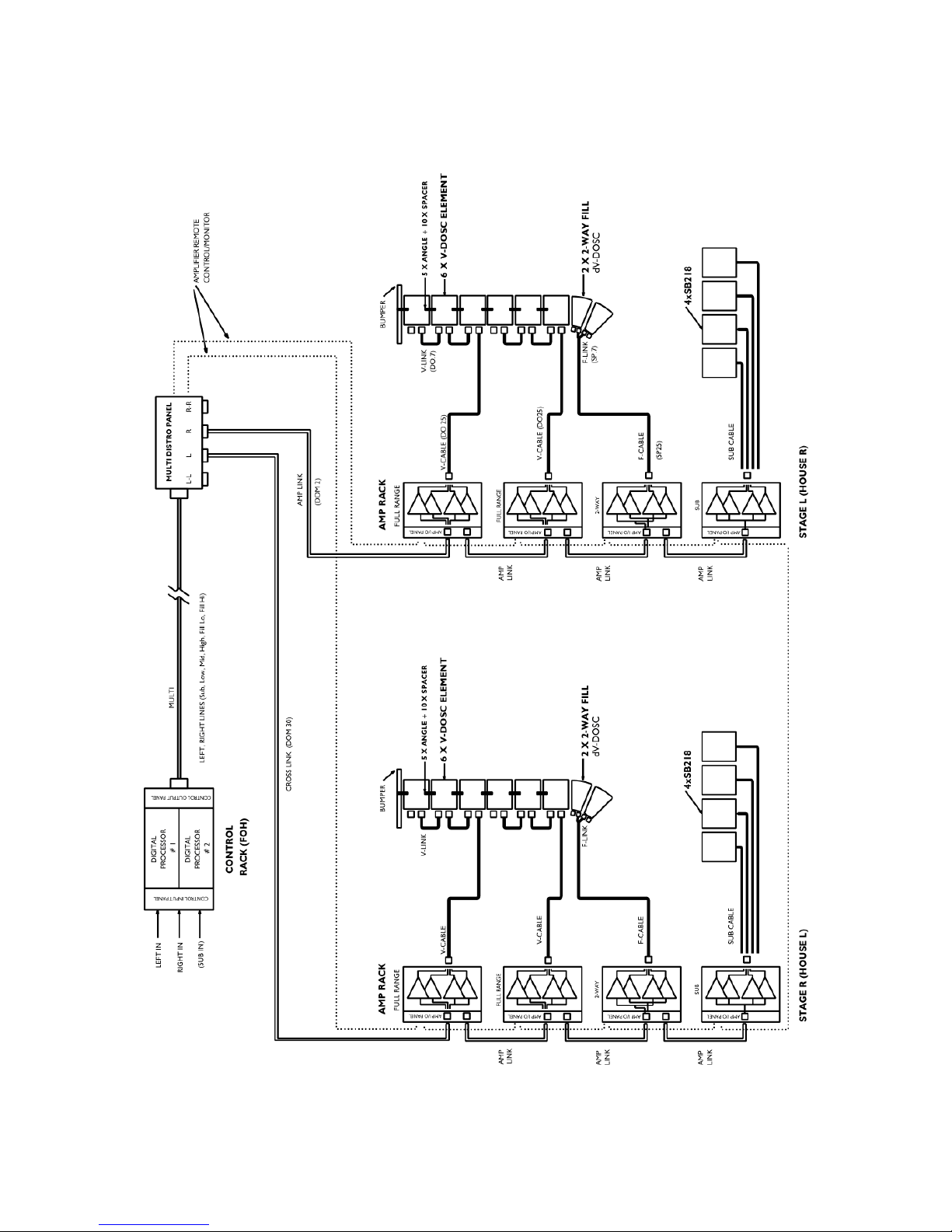
General System Block Diagram
A general block diagram representation of V-DOSC and dV-DOSC system components, cabling and
signal flow is given in Figure 3. Please refer to this for a general overview of the system.
Figure 3a: System Block Diagram
dV-DOSC dV-SUB Manual V2.0 Nov 2001
18
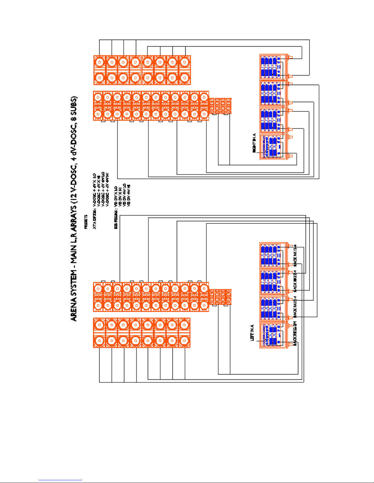
Figure 3b: Example System Configuration

dV-DOSC dV-SUB Manual V2.0 Nov 2001
19
1.1 dV-DOSC SYSTEM COMPONENTS
(1) dV-DOSC
Active 2-way loudspeaker enclosure, meeting Wavefront Sculpture Technology criteria, with
coplanar symmetric arrangement of loudspeaker components
(2) dV-SUB
Companion subwoofer for dV-DOSC with three 15-inch components mounted in a vented
bandpass configuration.
RIGGING
(3) dV-BUMP
Flying bumper for rigging dV-DOSC and/or dV-SUB. When combined with the V-DOSC
BUMPER, can be used as a stacking platform or for rigging dV-DOSC on top of V-DOSC
(4) dV-DOWN
Pair of flying bars for rigging dV-DOSC underneath V-DOSC
(5) dV-PIN25
Locking quick release pin (25 mm grip length) for physically interconnecting dV-DOSC or dVSUB enclosures. Six dV-PIN25 are required per 2 dV-DOSC enclosures along with 2 dV-ANGLE
(P1 or P2) bars.
(6) dV-PIN 81
Locking quick release pin (81 mm grip length) for physically connecting dV-DOSC to dVDOWN
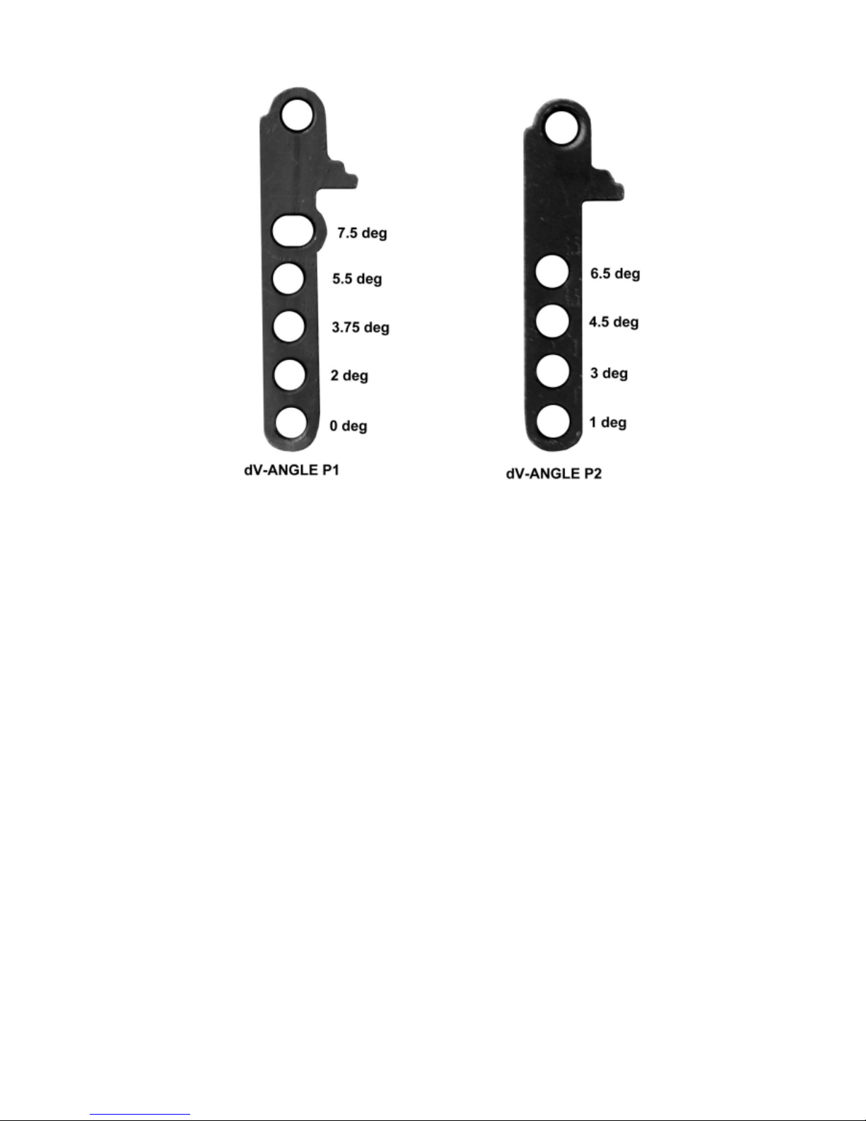
(7) dV-ANGLEP1, dV-ANGLEP2
Rear angle bar used to form convex (positive curvature) arrays. Available angles include:
P1: 0, 2, 3.75, 5.5, 7.5 degrees
P2: 1, 3, 4.5, 6.5 degrees
(8) dV-ANGLEN
Rear angle bar used to form concave (negative curvature) arrays or for downwards tilt of
stacked dV-DOSC systems. Available angles include: 0, -2, -3.75, -5.5 and -7.5 degrees
(9) dV-ANGLESS
Front and rear angle bar used to rig dV-SUB to dV-SUB (i.e., SS=sub to sub)
(10) dV-ANGLESD
Front angle bar used to rig dV-DOSC to dV-SUB (i.e., SD=sub to dV) or dV-SUB to dV-BUMP
(11) dV-ANGLESDP
Rear angle bar used to rig dV-DOSC to dV-SUB (i.e., SDP=sub to dV, positive tilt). Available
angles include: 0, 1.75, 3.75 degrees.
(12) FLIGHT-dV
Flight case for transport of three dV-DOSC enclosures
(13) dV-SUBPLA
Dolley board for dV-SUB
(14) dV-SUBCOV
Protective cover for dV-SUB
CABLING
(15) SUB CABLE (DOSUB)
Subwoofer loudspeaker cable, 5 m (16 ft) length, with male 8 pin CA-COM connector and four
Speakon connectors (for connecting 4x dV-SUB or 4x SB218 subwoofers to amplifier racks)
dV-DOSC dV-SUB Manual V2.0 Nov 2001
20
(16) SUB EXTENSION CABLE (DO10P)
Subwoofer extension cable ,10 m length for use with DOSUB
(17) SP.7
Loudspeaker cable, 0.7 m length, four conductor (4 mm
2
cross sectional area per conductor)
terminated in locking Speakon connectors. Used for parallel linking of dV-DOSC enclosures
(18) SP7
Loudspeaker cable, 7 m length, four conductor (4 mm
2
cross sectional area per conductor)
terminated in locking Speakon connectors
(19) SP25
Loudspeaker cable, 25 m length, four conductor (4 mm
2
cross sectional area per conductor)
terminated in locking Speakon connectors
(20) DOFILL
CA-COM (8 pin male barrel) to dual locking Speakon adaptor, 3 m length. For use with VDOSC cables DO7 and DO25 for breakout and connection at the loudspeaker end
(21) DO2W
CA-COM (8 pin male - barrel plus coupling ring) to dual locking Speakon adaptor, 3 m length.
For breakout at the amplifier rack and connection via two CC4FP and two standard Speakon
cables SP7 or SP25
(22) CC4FP
Speakon to speakon adaptor (female-female)
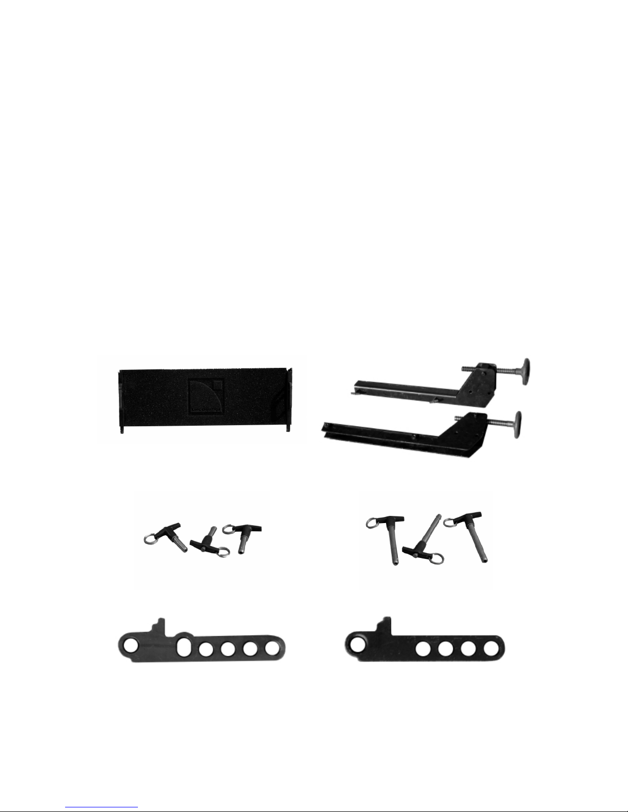
dV-DOSC
dV-DOWN
dV-PIN25 dV-PIN81
dV-ANGLEP1
(0, 2, 3.75, 5.5, 7.5 deg)
dV-ANGLEP2
(1, 3, 4.5, 6.5 deg)
dV-DOSC dV-SUB Manual V2.0 Nov 2001
21
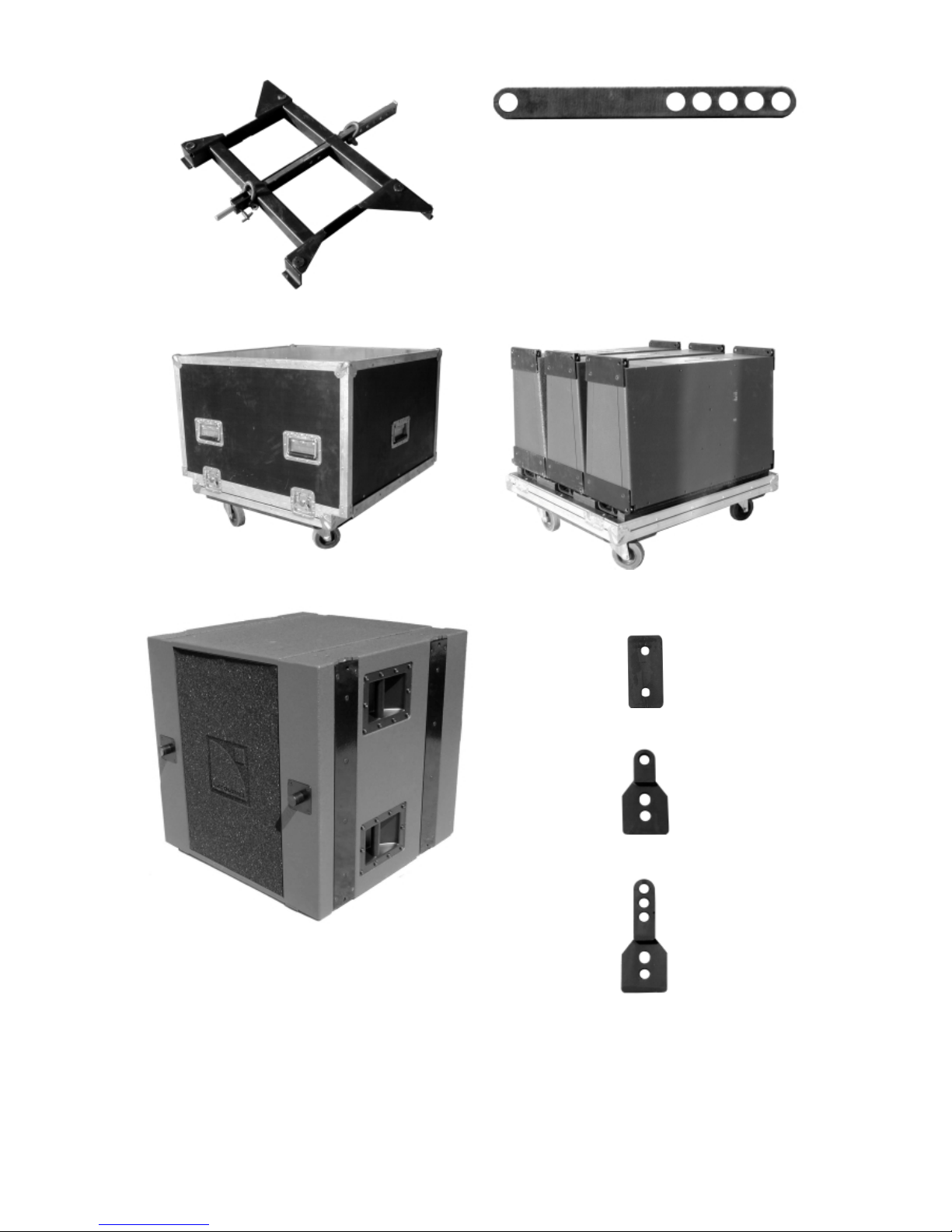
dV-BUMP
dV-ANGLEN
(0, -2, -3.75, -5.5, -7.5 degrees)
FLIGHT-dV FLIGHT-dV
dV-SUB
dV-ANGLESS
dV-ANGLESD
dV-ANGLESDP
dV-DOSC dV-SUB Manual V2.0 Nov 2001
22
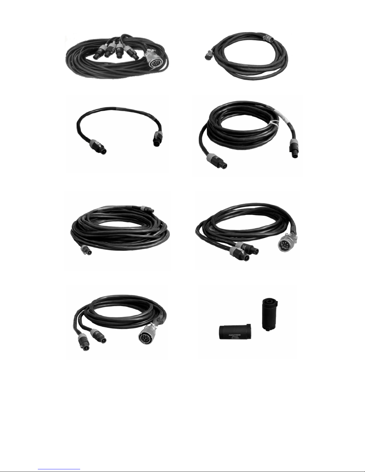
SUB CABLE DOSUB
SUB EXTENSION DO10P
SP.7
SP7
SP25
DOFILL
DO2W
CC4FP
Figure 4: dV-DOSC and Accessories (not to scale)

dV-DOSC dV-SUB Manual V2.0 Nov 2001
23
1.2 dV-DOSC ENCLOSURE DESCRIPTION
Figure 5: dV-DOSC Element - Front and Rear Views
dV-DOSC contains two 8" loudspeakers (connected in parallel) and a 1.4" exit compression driver
mounted on a custom DOSC waveguide. The 8'' loudspeakers are individually rated at 16 ohms and
connected in parallel to provide a nominal impedance of 8 ohms. The nominal operating bandwidth
for the 8'' section is 100 Hz to 800 Hz. A surface coating is applied to the composite cellulose fibre
cone body and all metal parts are corrosion-treated to ensure weather resistant protection. Other
features include: rugged kevlar dustcap, 2'' diameter edgewound copper voice on a polyimide
former, high excursion/reduced fatigue suspension and a compact, high flux density magnetic system.
Nominal impedance for the high section is 8 ohms and the compression driver employed in dVDOSC features a 1.4'' exit, titanium diaphragm, 3'' diameter edgewound aluminum voice coil and a
lightweight neodymium magnet. These features combine to provide high sensitivity and power
handling with low distortion over the entire operating bandwidth (800 - 18k Hz). A removable rear
panel allows access to the compression driver for servicing the diaphragm.
Each dV-DOSC element is provided with two Speakon connector sockets for direct connection and
paralleling of up to three enclosures. Elements are paralleled using SP.7 loudspeaker cables (0.7 m
length). Direct connection of elements to the AMP RACK is made using SP7 or SP25 (7 m or 25 m
length, as required) in conjunction with the DO2W adapter and two CC4F. Alternatively, connection
can be made using standard V-DOSC cables (DO7 or DO25) and the DOFILL adapter (8 pin male
CA-COM barrel to dual speakon breakout).
The bandwidth of dV-DOSC is 100 Hz to 18 kHz. For extended bandwidth applications, the addition
of dV-SUB or SB218 subwoofers is recommended in order to extend the response to 25Hz and
increase the available headroom in the extreme low frequency range.
1.3 dV-DOSC FLYING SYSTEM
Flying a dV-DOSC array is easy, fast and secure since the trapezoidal shape of the enclosure and
integral rigging plates allow for efficient stacking, transport and handling. dV-DOSC features a unique
flying system where rear mounted angle bars are used to control the angle between enclosures, i.e.,
cabinets pivot about the front mount points and selecting the desired hole on the rear angle bars
adjusts the angle between enclosures. When dV-ANGLE P1 or P2 bars are used, convex (positive
curvature) arrays can be constructed ranging from flat up to a maximum of 7.5 degrees between
cabinets in increments of approximately 1 degree. When dV-ANGLEN bars are used, concave
(negative curvature) arrays can be constructed ranging from flat up to a maximum of minus 7.5
degrees between cabinets in increments of approximately 1.75 degrees.
dV-DOSC dV-SUB Manual V2.0 Nov 2001
24
Figure 6: dV-ANGLE P1 and P2 angle values
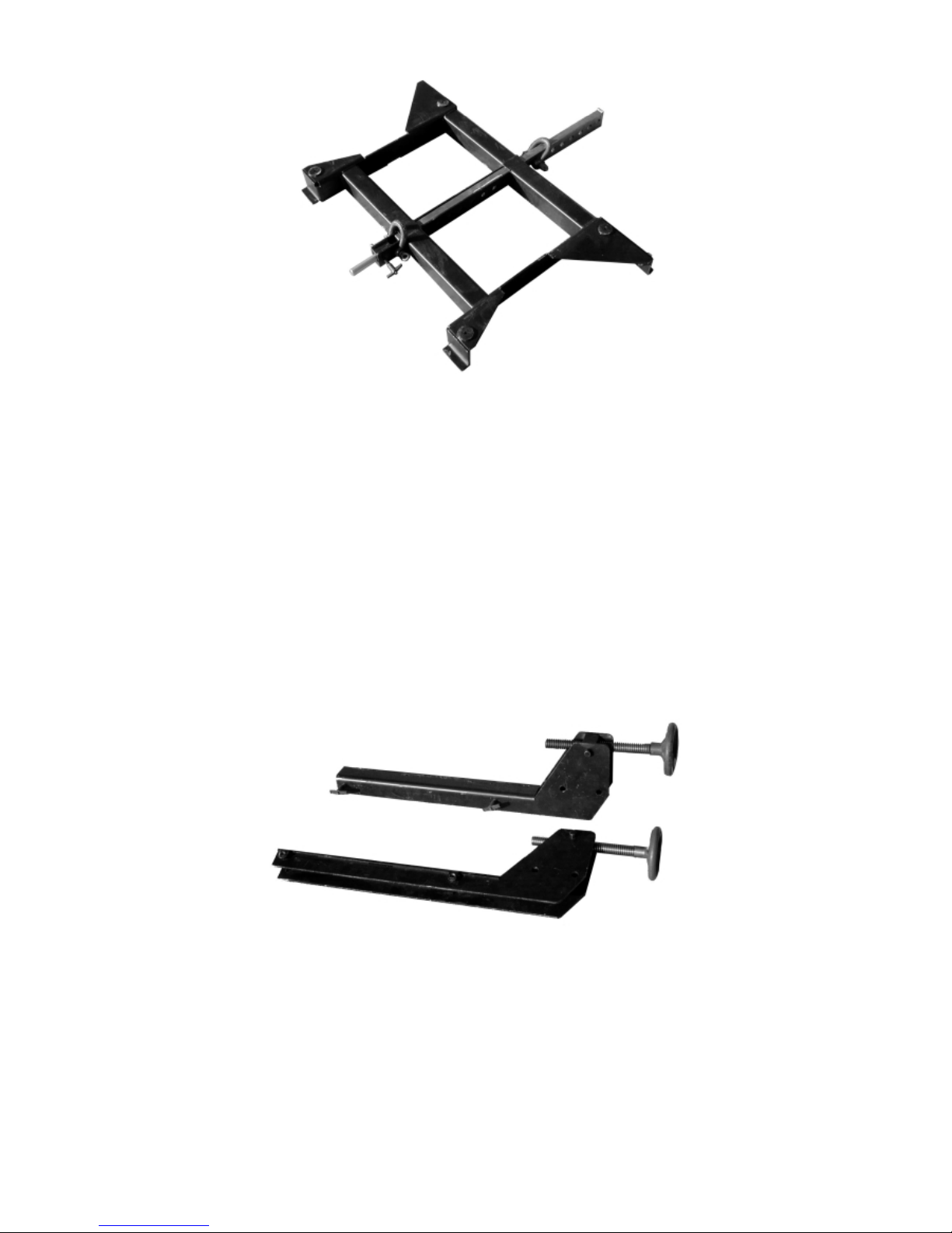
The dV-BUMP flying bumper can be used for rigging dV-DOSC standalone or for a variety of
stacking applications. For standalone flying, there are 8 pick point holes available on the central
spreader bar section of dV-BUMP for single point hangs (pick point hole numbering is 1-8 from front
to rear). An extension bar can be added to dV-BUMP to provide an additional 8 pick points for single
point hangs (pick point hole numbering is 9-16 from front to rear) or to allow for 2 point hangs with
front and rear motors similar to the manner in which V-DOSC is flown (note: the front motor
controls array trim height while the rear motor controls array tilt and focus - this is due to the fact
that the dV-DOSC rigging system pivots around the front, not the rear as is the case for V-DOSC).
For a tightly wrapped array of 12 dV-DOSC, 90 degrees vertical coverage is obtained. For this case,
when the rear-most point on the extension bar is used for a single point hang, the 90 degree
coverage runs from parallel to the floor to perpendicular to the floor.
Note: For single point hangs, array tilt angles obtained will depend on the size and shape of the array since
these factors alter the center of gravity of the overall flown system.
dV-BUMP also allows for three different stacking options:
1) stacking platform with variable tilt adjustment for stacked dV-DOSC applications;
2) stacking platform for rigging dV-DOSC on top of V-DOSC;
3) stacking platform for rigging dV-DOSC on top of SB218 or dV-SUB subwoofers.
Note: Options 1) and 2) are achieved by mechanically connecting dV-BUMP to the V-DOSC
BUMPER.
dV-DOSC dV-SUB Manual V2.0 Nov 2001
25
Figure 7: dV-BUMP
Maximum recommended flown configurations are summarized as follows:
dV-BUMP ONLY
(SINGLE POINT HANG FROM CENTRAL SPREADER BAR POINTS)
- maximum 24 dV-DOSC elements
dV-BUMP + EXTENSION BAR
(SINGLE POINT HANG FROM REAR EXTENSION BAR POINTS)
- maximum 12 dV-DOSC elements
dV-BUMP + EXTENSION BAR
(2 POINT HANG FROM dV-BUMP FRONT POINT AND EXTENSION BAR REAR POINT)
- maximum 12 dV-DOSC elements
Figure 8: dV-DOWN
With dV-DOWN, up to a maximum of 6 dV-DOSC can be flown underneath V-DOSC for downfill
applications. Three dV-DOSC are equivalent to the weight of one V-DOSC, therefore maximum
cabinet combinations include: 15 V-DOSC plus 3 dV-DOSC or 14 V-DOSC plus 6 dV-DOSC.
dV-DOSC dV-SUB Manual V2.0 Nov 2001
26
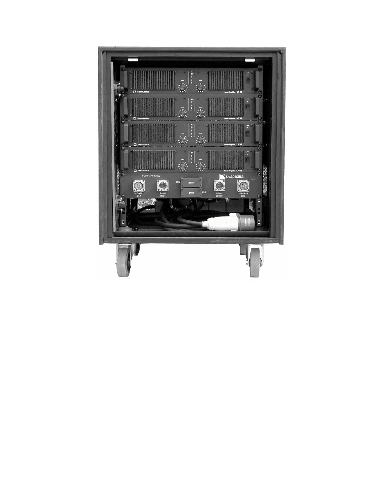
1.4 dV-DOSC AMPLIFIER RACKS
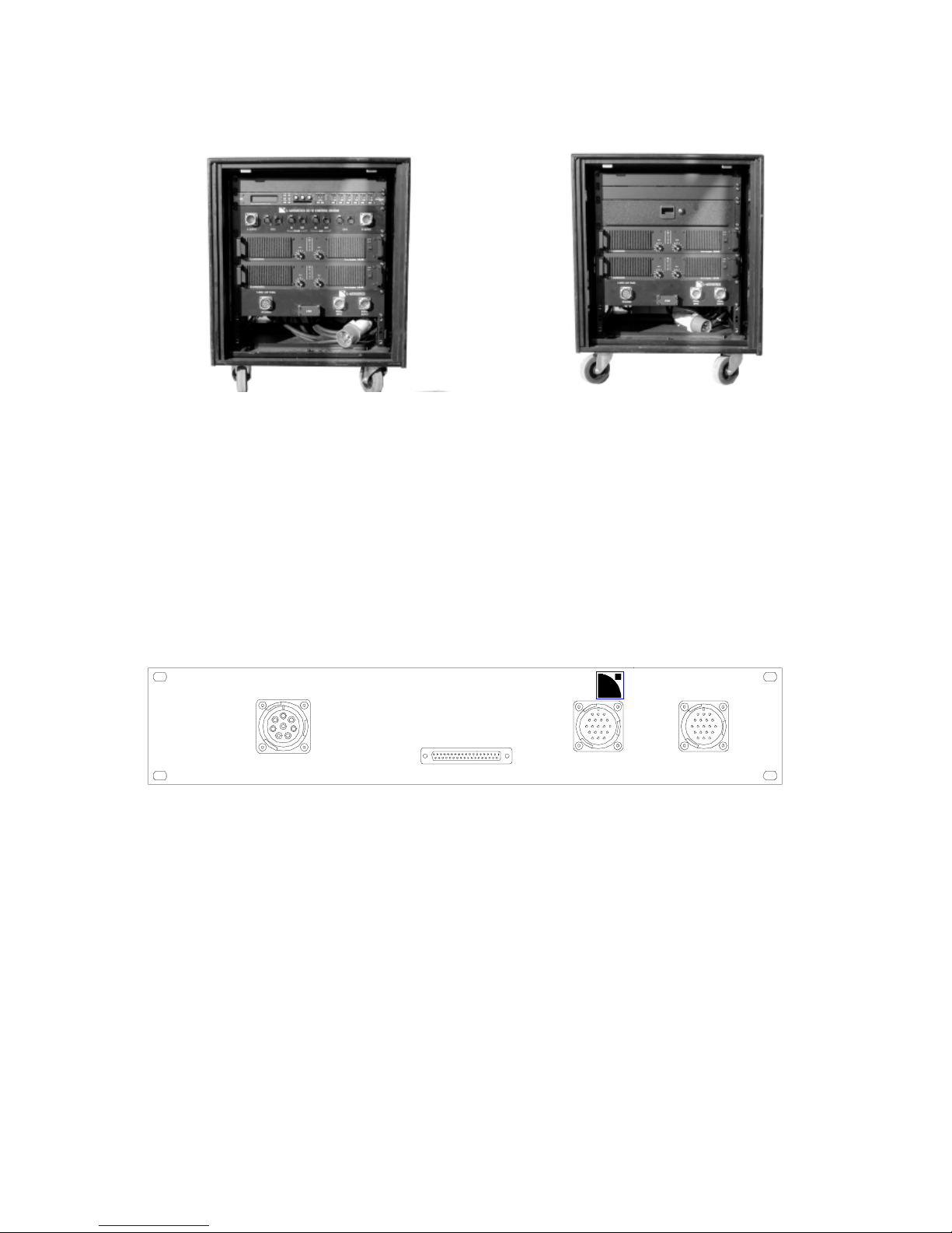
Figure 9: L-ACOUSTICS AMP RACK RK12-4
The standard L-ACOUSTICS RK12-4 amplifier rack is twelve rack units high and contains four LACOUSTICS LA 48 amplifiers. Overall external dimensions are 77 cm high (including casters) x 61
cm wide x 58 cm deep (30.3 x 26.4 x 22.9 inches). Clearance from the front rack rail to the front of
the rack is 9.5 cm (3.7 in). Clearance from the rear rack rail to the rear of the rack is 6 cm (2.4 in).
The depth from front to rear rack rails is 42.5 cm (16.7 in) and the depth from front rack rail to the
rear support points for the LA 48 amplifier is 39 cm (15.35 in). Due to the switch mode power
supply technology employed in the L-ACOUSTICS LA 48, the rack weighs only 98 kg (216 lbs)!
Using the COMB connectors located on the Amp Panel (PAD04), the rack can be configured so that
A and B channels are independent. Depending on how the rack is to be configured 2-WAY, 3-WAY
or SUB COMB connectors are selected. The COMB connectors route the desired input lines from
the 19 pin CA-COM connector via internal XLR breakouts to the appropriate amplifier inputs for A
and B channels, respectively. Using separate COMB connectors for both channels, it is possible to
assign the A channels and the B channels independently. Therefore, half an amplifier rack can power
up to 3 V-DOSC (6 total), 4 SB218 or 4 dV-SUB subwoofers (8 total) or 6 dV-DOSC (12 total).
In terms of construction, the amplifier rack is made of a lightweight aluminum space frame with
heavy duty bracing, internal shock mounting, standard rack rails and provision for rear support of
amplifiers. Clear, unbreakable polycarbonate (lexan) front and rear doors allow the user to see how
the racks are configured and can be conveniently stored in the sides of the rack during use (note: for
ventilation purposes, front and rear doors must always be removed during operation). A high impact
dV-DOSC dV-SUB Manual V2.0 Nov 2001
27
resistant polyethylene cover provides protection for the rack during transport so that no external
case is required. Four recessed Aeroquip flytrack sections are mounted on both sides of the amplifier
rack for flying applications.
There are recesses in the top cover of each rack that allow racks to be stacked on top of each other
with the castors still attached. It is also possible to remove the casters on one amplifier rack, place it
on top of a second amp rack and then mechanically bolt the two racks together. Overall the LACOUSTICS amplifier rack provides an extremely efficient package in terms of power versus size
and weight while at the same time maintaining flexibility for smaller scale and distributed system
applications.
NOTE: As installed in RK12-4, all L-ACOUSTICS LA 48 amplifiers are rear supported. Rear support of LACOUSTICS LA amplifiesr is strongly recommended for all portable or touring sound applications.
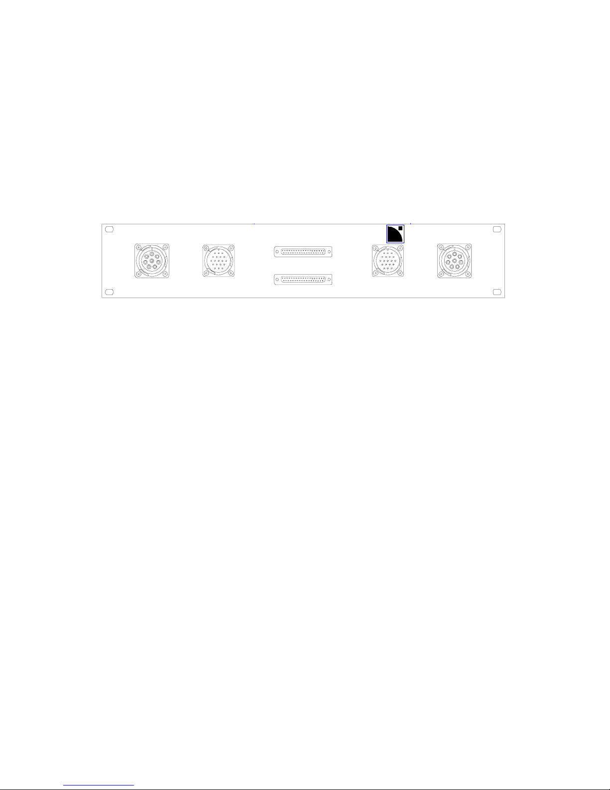
SIGNAL
INPUT
SIGNAL
OUTPUT
SPEAKERS - CH A
SPEAKERS - CH B
CH A
CH B
V-DOSC AMP PANEL
L-ACOUSTICS
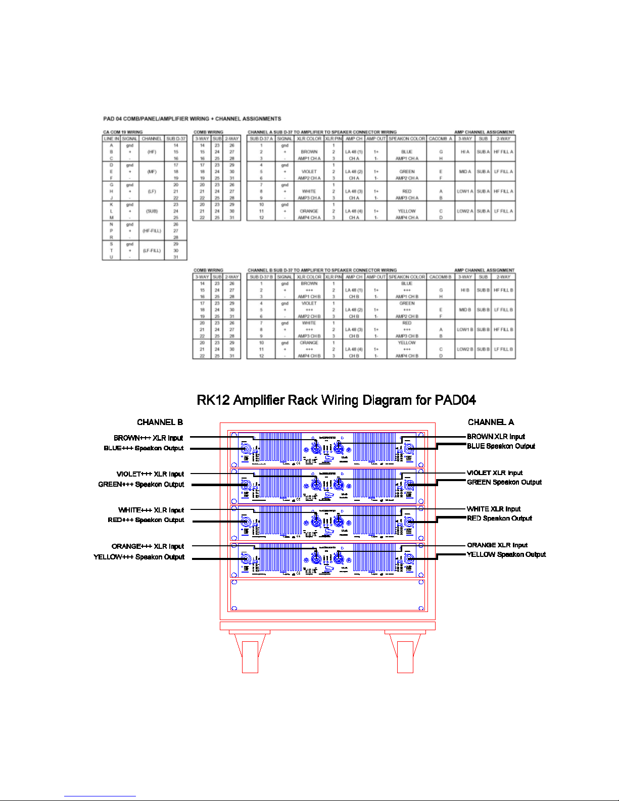
Figure 10: PAD 04 (4 amplifiers per rack)
The PAD04 panel is intended for 4 amplifier-per-rack packaging and allows for connection of
loudspeakers, input signal and output signal loop through. The panel has dual 8 pin female CA-COM
connectors for loudspeaker connection and two male 19 pin CA-COM connectors for input signal
connection (using either AMP LINK or CROSS LINK cables) and for jumping to subsequent amp
racks (using AMP LINK cables). Ch A and Ch B COMB connectors allow the rack to be configured
for either 2-way, 3-way or SUB operating modes.
Internally, two sets of 4X male XLR fanouts connect the input signal from the 37-pin Dsub
connector via the COMB connector on PAD04 to the amplifier inputs. For the CA-COM connector,
lines 5 and 6 are always assigned to 2-way fill (high and low, respectively). Line 4 is reserved for
subwoofer drive while lines 1, 2 and 3 are for V-DOSC high, mid and low, respectively. For
complete details regarding CA-COM line assignments, PAD04 wiring and COMB connector wiring,
please refer to the table below.
In 3-way mode, 8 pin loudspeaker CA-COM pinouts for channels A and B are as follows:
A/B = V-DOSC LOW AMP#3 +/-
C/D = V-DOSC LOW AMP#4 +/-
E/F = V-DOSC MID AMP#2 +/-
G/H = V-DOSC HIGH AMP#1 +/-
In 2-way mode, 8 pin loudspeaker CA-COM pinouts for channels A and B are as follows:
A/B = HF AMP#3 +/-
C/D = LF AMP#4 +/-
G/H = HF AMP#1 +/-
E/F = LF AMP#2 +/- .
Either DOFILL or DO2W adapters are used to convert from 8 pin CA-COM to dual Speakon
connectors. Individual Speakon pinouts are : +1/-1 = dV-DOSC LF +/- ; +2/-2 = dV-DOSC HF +/.
dV-DOSC dV-SUB Manual V2.0 Nov 2001
28
Table 1: PAD04 Amp Panel Wiring Chart
dV-DOSC dV-SUB Manual V2.0 Nov 2001
29
L-ACOUSTICS RK12-2M and RK12-2S are examples of two-amplifier-per-rack packaging. RK12-2M
includes a digital processor plus CD12 Control Distribution Panel and can act as a standalone master
rack. RK12-2S contains 2 amplifiers (plus storage drawer) and acts as a slave rack.
RK12-2M Master Rack
RK12-2S Slave Rack
Figure 11: RK12-2M and RK12-2S Master and Slave Racks
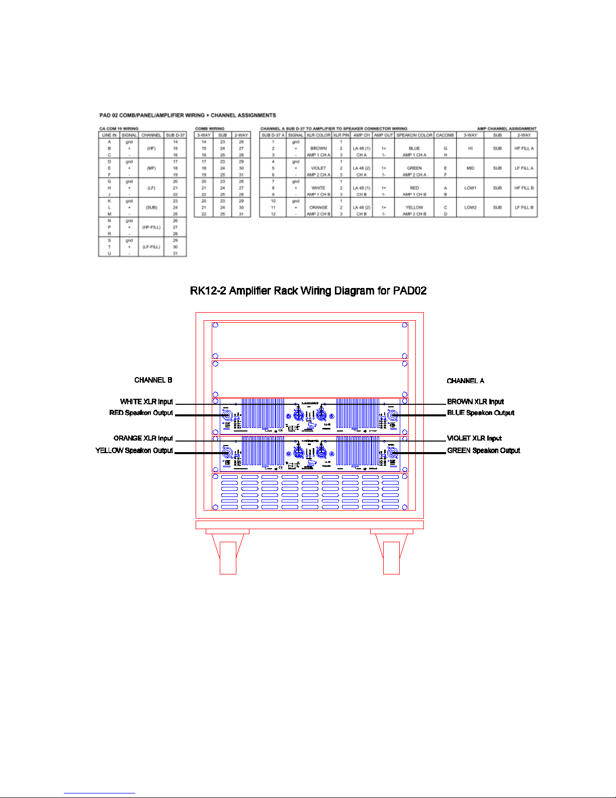
For RK12-2M and RK12-2S, amplifier rack panel PAD02 is employed. With two LA 48 amplifiers per
rack, up to 3+3 dV-DOSC can be powered whereas two LA 24 are suitable for powering up to 2+2
dV-DOSC. Just as for PADO4, PADO2 allows for connection of loudspeakers, input signal and
output signal loop through. The panel has a single 8 pin female CA-COM connector for loudspeaker
connection and two male 19 pin CA-COM connectors for input signal connection (using either AMP
LINK or CROSS LINK cables) and for jumping to subsequent amp racks (using AMP LINK cables).
COMB connectors allow the user to reconfigure the AMP RACK for either 2-way, 3-way or SUB
operating modes.
SPEAKERS
SIGNAL
INPUT
SIGNAL
OUTPUT
V-DOSC AMP PANEL
L-ACOUSTICS
Figure 12: PAD 02 (2 amplifiers per rack)
Internally, a set of 4X male XLR fanouts connect the input signal from the COMB connector on
PAD02 to the amplifier inputs. For the CA-COM connector, lines 5 and 6 are always assigned to 2way fill (high and low, respectively). Line 4 is reserved for subwoofer drive while lines 1, 2 and 3 are
for V-DOSC high, mid and low, respectively.
In 2-way mode, 8 pin loudspeaker CA-COM pinouts are as follows:
A/B = HF (Top Amplifier, Channel A +/-)
C/D = LF (Bottom Amplifier Channel A +/-)
G/H = HF (Top Amplifier Channel B +/-)
E/F = LF (Bottom Amplifier Channel B+/-).
Either DOFILL or DO2W adapters are used to convert from 8 pin CA-COM to dual Speakon
connectors. Individual Speakon pinouts are : +1/-1 = dV-DOSC LF +/- ; +2/-2 = dV-DOSC HF +/.
dV-DOSC dV-SUB Manual V2.0 Nov 2001
30
Table 2: PAD02 Amp Panel Wiring Chart
 Loading...