

Page 1

Version 1.1
February 2003
L-ACOUSTICS XT LINE
112XT, 115XT
OPERATOR MANUAL
Page 2

L-ACOUSTICS XT Manual V1.1 2/11/2003 1
FOREWORD
Thank you for purchasing the 112XT or 115XT sound reinforcement system.
This manual is intended to provide you with the information you require to install and operate your
XT loudspeaker enclosure in a wide variety of professional sound reinforcement applications.
Specific information and recommendations are included regarding system design, sound design and
installation. We are confident that the information provided in this manual will be sufficient for most
applications, however, should you require further assistance your distributor or L-ACOUSTICS
®
are
available to provide additional technical support.
MANUAL ORGANIZATION
! The Introduction gives a brief presentation of coaxial technology and the XT system.
! Chapter 1 introduces the 112XT and 115XT loudspeaker enclosures plus accessories
! Chapter 2 discusses 112XT and 115XT power amplification and cabling
! Chapter 3 describes preset selection and system operation
! Chapter 4 discusses sound design aspects
! Chapter 5 describes 112XT or 115XT installation procedures
! Chapter 6 discusses XT system operation and maintenance procedures
! Chapter 7 gives 112XT and 115XT specifications
Page 3

L-ACOUSTICS XT Manual V1.1 2/11/2003 2
Page 4

L-ACOUSTICS XT Manual V1.1 2/11/2003 3
TABLE OF CONTENTS
FOREWORD.............................................................................................................................................. 1
MANUAL ORGANIZATION....................................................................................................................1
TABLE OF CONTENTS............................................................................................................................3
LIST OF FIGURES..................................................................................................................................... 4
LIST OF TABLES ......................................................................................................................................4
0. INTRODUCTION ................................................................................................................................. 5
1. THE XT SYSTEM..................................................................................................................................6
1.1 XT SYSTEM COMPONENTS......................................................................................................................... 6
1.2 XT OVERVIEW............................................................................................................................................. 9
1.3 112XT SPECIFICATIONS ............................................................................................................................ 10
1.4 115XT SPECIFICATIONS ............................................................................................................................ 11
2. POWERING XT ..................................................................................................................................12
2.1 POWERING 112XT.................................................................................................................................... 12
2.2 POWERING 115XT.................................................................................................................................... 14
2.3 CONNECTORS AND CABLES ..................................................................................................................... 17
3. XT CONTROL AND PROCESSING..................................................................................................17
3.1 GENERAL DESCRIPTION OF XT PRESETS.................................................................................................. 18
3.2 XT PRESET POLICY .................................................................................................................................... 18
3.3 GUIDELINES REGARDING SYSTEM PROTECTION..................................................................................... 19
3.4 XT PRESET LIBRARIES............................................................................................................................... 20
4. SOUND DESIGN ................................................................................................................................26
4.1 APPLICATIONS ........................................................................................................................................... 26
4.2 AIMING XT ENCLOSURES ......................................................................................................................... 26
4.3 ARRAYING XT ENCLOSURES ..................................................................................................................... 27
4.4 PREDICTING XT COVERAGE ..................................................................................................................... 30
4.5 DISTRIBUTED SOUND REINFORCEMENT................................................................................................. 30
4.5.1 OVERHEAD DISTRIBUTED SYSTEMS ............................................................................................ 30
4.5.2 DELAY SYSTEMS .............................................................................................................................. 30
4.5.3 COMPLEMENTARY FILL ................................................................................................................. 31
4.6 FRONT-OF-HOUSE (FOH) APPLICATIONS ................................................................................................ 32
4.7 STAGE MONITORING................................................................................................................................ 32
4.8 USING XT WITH SUBWOOFERS............................................................................................................... 34
4.8.1 COMBINING XT WITH SUBWOOFERS ........................................................................................ 35
4.8.2 GROUND STACKED SYSTEMS....................................................................................................... 35
4.8.3 SEPARATE FLOWN XT ARRAY WITH GROUND STACKED SUBWOOFERS ............................. 35
5. INSTALLATION PROCEDURES .......................................................................................................37
5.1 ETR112XT, ETR115XT U-BRACKET ATTACHMENT .................................................................................. 37
5.2 CPL112XT, CPL115XT COUPLING ADAPTER BAR ATTACHMENT ............................................................. 38
5.3 XTLIFTBAR ATTACHMENT ........................................................................................................................ 40
5.4 SAFETY RULES ........................................................................................................................................... 40
6. XT SYSTEM OPERATION .................................................................................................................41
6.1 RECOMMENDED MAINTENANCE PROCEDURES ..................................................................................... 41
6.2 SPARE PARTS.............................................................................................................................................. 42
7. SPECIFICATIONS ..............................................................................................................................43
7.1 112XT ELEMENT SPECIFICATIONS ........................................................................................................... 43
7.2 115XT ELEMENT SPECIFICATIONS ........................................................................................................... 47
Page 5

L-ACOUSTICS XT Manual V1.1 2/11/2003 4
LIST OF FIGURES
Figure 1: XT System Components .................................................................................................................... 8
Figure 2: 112XT Enclosure.............................................................................................................................. 10
Figure 3: 115XT Enclosure.............................................................................................................................. 11
Figure 4: MLS switches on the rear panel of L-ACOUSTICS LA24a, LA48a amplifiers..................................14
Figure 5: L-ACOUSTICS preset library for XTA DP224 ................................................................................21
Figure 6: L-ACOUSTICS preset library for XTA DP226 ................................................................................22
Figure 7: L-ACOUSTICS preset library for BSS FDS-334 Minidrive ............................................................... 23
Figure 8: L-ACOUSTICS preset library for BSS FDS-336 Minidrive ............................................................... 24
Figure 9: L-ACOUSTICS preset library for BSS FDS-366 Omnidrive Compact Plus ....................................25
Figure 10: General guidelines for aiming XT enclosures................................................................................. 27
Figure 11: SPL mappings at octave band frequencies for a single XT enclosure............................................. 27
Figure 12: SPL mappings at octave band frequencies for two XT enclosures with 0.5 metre spacing...........28
Figure 13: SPL mappings at octave band frequencies for two XT enclosures with 3 metre spacing..............28
Figure 14: General guidelines for arraying XT enclosures.. ............................................................................29
Figure 15: SPL mappings at octave band frequencies for four XT enclosures with 0.5 metre spacing........... 29
Figure 16: L-ACOUSTICS Subwoofer Continuous Unweighted SPL Comparison......................................... 34
Figure 17: Illustration of subwoofer time alignment........................................................................................ 36
Figure 18: ETR112XT, ETR115XT U-bracket installation procedure ............................................................38
Figure 19: CPL112XT, CPL115XT coupling adapter installation procedure..................................................39
Figure 20: XTLIFTBAR installation procedure ................................................................................................ 40
Figure 21: 112XT Line Drawing...................................................................................................................... 44
Figure 22: 112XT + ETR112XT Line Drawing............................................................................................... 45
Figure 23: 112XT + XTLIFTBAR Line Drawing.............................................................................................45
Figure 24: 112XT + ETR112XT + 112CPLXT Line Drawing (0 degree) .....................................................46
Figure 25: 112XT + ETR112XT + 112CPLXT Line Drawing (30 degrees)..................................................46
Figure 26: 115XT Line Drawing...................................................................................................................... 48
Figure 27: 115XT + ETR115XT Line Drawing............................................................................................... 49
Figure 28: 115XT + XTLIFTBAR Line Drawing.............................................................................................49
Figure 29: 115XT + ETR115XT + 115XTCPL Line Drawing (0 degrees)....................................................50
Figure 30: 115XT + ETR115XT + 115XTCPL Line Drawing (30 degrees)..................................................50
LIST OF TABLES
Table 1: Load and Power Ratings for 112XT .................................................................................................. 12
Table 2: Recommended power amplification and MLS switch settings for 112XT low section ..................... 13
Table 3: Recommended power amplification and MLS switch settings for 112XT high section ....................13
Table 4: Recommended MLS switch settings for powering 112XT................................................................14
Table 5: Load and Power Ratings for 115XT .................................................................................................. 14
Table 6: Recommended power amplification and MLS switch settings for 115XT low section ..................... 15
Table 7: Recommended power amplification and MLS switch settings for 115XT high section ....................15
Table 8: Recommended MLS switch settings for powering 115XT................................................................15
Table 9: Output Power Ratings and MLS Switch Settings for L-ACOUSTICS LAa Amplifiers .......................16
Table 10: Maximum Recommended Length for Damping Factor > 20.......................................................... 17
Table 11: Nominal floor monitor distance and monitor separation versus performer height ........................ 33
Table 12: L-ACOUSTICS Subwoofer Specification Summary......................................................................... 34
Page 6

L-ACOUSTICS XT Manual V1.1 2/11/2003 5
0. INTRODUCTION
Effectively covering an audience is the goal of any sound reinforcement system design. This is
straightforward in small spaces where a left/right stereo configuration is suitable provided that the
available power is sufficient, i.e., a stereo pair of loudspeakers is a relatively easy system to install and
the results are fairly predictable. Things become more complex when larger audience area coverage is
required and there are two possible approaches:
1) Multiplying the number of sound sources by dividing the audience into areas which are covered by
individual sources. In this case, the Haas effect is exploited and the goal is to reduce audible
interference effects by dissociating or decoupling the individual sound sources (delay lines can also be
introduced to provide proper localization). This is the distributed sound reinforcement, or multiple
sound source approach, and the XT line of enclosures is highly suited for this type of sound design.
2) Coupling a number of individual sound sources to form a loudspeaker array, with the objective that
each array becomes the equivalent of a single sound source.
For the second approach, conditions for achieving proper coupling of individual arrayed sound sources
have been defined by Dr. Christian Heil and Professor Marcel Urban, in "Sound Fields Radiated By
Multiple Sound Source Arrays" (AES paper preprint 3269, presented at the 92nd AES convention in
Vienna, 1992). Additional conditions were published in the AES preprint ''Wavefront Sculpture
Technology'' (WST) that was presented at the 111
th
Convention, NYC, 2001 (preprint 5488). The
theory that was developed defines the acoustic coupling conditions required for effectively arraying
individual sound sources. These conditions are satisfied by the ARCS
®
, dV-DOSC™ and V-DOSC®
products which are intended for medium- to large-scale sound reinforcement applications. However,
in most cases, it is not feasible to meet WST criteria while at the same time having a sufficient level of
versatility for small- to medium-scale applications. In other words, if a product is to be arrayable, it
typically leads to an enclosure design that cannot be used in single or very small configurations. A
different set of loudspeaker enclosure design specifications apply that are more suited to the multiple
source sound design approach.
The L-ACOUSTICS approach to distributed sound reinforcement using multiple sound sources starts
with the specification that each individual loudspeaker enclosure should behave as a totally coherent
source. This criterion can be achieved using coaxial components which are well-suited to the design of
highly versatile, small format systems. The use of coaxial components has been popularized over the
years by a famous British manufacturer for studio monitoring applications – to the best of our
knowledge, L-ACOUSTICS was the first manufacturer to use coaxial technology in professional sound
reinforcement applications and the current XT line is a continuation of the heritage that was
introduced in 1989.
Coaxial, dual concentric components provide a smooth transition between the LF and HF sections
since, by definition, the directivity of the two transducers is matched at the crossover frequency. In
addition, the directivity is horizontally, vertically and diagonally symmetric (axi-symmetric). This
results in true, single source behavior and the performance obtained is superior in terms of coherence
when compared with any combination of two independent sound sources (separate woofer plus hornloaded compression driver, for example). This is the case even if the independent sources are
designed to provide the same directivity behavior (which is rarely the case) since the acoustic centers
of the two sources are not located at the same physical location.
Other benefits obtained using the coaxial, axi-symmetric configuration are smooth acoustical
impedance loading for the compression driver and a short time window of reflections which is far
more acceptable than the longer reflection sequences that are produced by traditional horn designs. In
addition, the wavefront radiated by an axi-symmetric sound source has directivity that is smoothly
increasing with frequency which helps to match the acoustical environment of a typical auditorium.
Normally, the reverberation time in auditoria decreases smoothly above 1 kHz and at greater
distances in the venue, the low frequency energy is fairly constant due to the reverberant field.
Page 7

L-ACOUSTICS XT Manual V1.1 2/11/2003 6
Loudspeaker focus or aiming can be adjusted so that maximum HF energy is directed towards the
farthest listening areas, therefore balancing the SPL attenuation with distance that occurs in the direct
field. At closer listening positions, the off-axis attenuation at higher frequencies provides a similar tonal
balance and the attenuation with distance is less.
The coaxial configuration therefore provides the optimum directivity required in order to obtain even
coverage and constant tonal balance in a typical semi-reverberant auditorium. Extensive sound design
and installation experience acquired by L-ACOUSTICS over the years confirms this and we are
confident that coaxial, axi-symmetric loudspeaker enclosures are the best tools for multiple source,
distributed sound design.
The coaxial performance of the 112XT and 115XT loudspeaker enclosures provide the basic starting
tools for distributed sound reinforcement design.
1. THE XT SYSTEM
The XT line consists of: 112XT, 115XT loudspeaker enclosures, XT rigging accessories and SB115,
SB118, SB218 or dV-SUB subwoofers. OEM factory presets are provided for approved digital signal
processors (XTA DP224, DP226 and BSS 366). Please note that amplifier racks plus loudspeaker
cables are not specified but should meet the minimum specification requirements outlined below.
1.1 XT SYSTEM COMPONENTS
LOUDSPEAKER ENCLOSURES
(1) 112XT
Active 2-way coaxial loudspeaker with 90 degree axi-symmetrical coverage, containing 12”
loudspeaker, 1.4” exit high frequency compression driver
(2) 115XT
Active 2-way coaxial loudspeaker with 80 degree axi-symmetrical coverage, containing 15”
loudspeaker, 1.4” exit high frequency compression driver
SUBWOOFER ENCLOSURES
(3) SB115
Front-loaded, bass-reflex design, single 15’’ subwoofer for low frequency extension
(4) SB118
Dual-vented bandpass-loaded, single 18’’ subwoofer for high level, extended bandwidth
(5) SB218
Front-loaded, bass-reflex design, dual 18’’ subwoofer for high level, extended bandwidth
(6) dV-SUB
Dual-vented bandpass-loaded triple 15” subwoofer for high level, low frequency extension
For more information concerning SB115, SB118 and SB218 subwoofer enclosures please consult the SB
Subwoofer User’s Manual
Page 8
L-ACOUSTICS XT Manual V1.1 2/11/2003 7
XT RIGGING ACCESSORIES
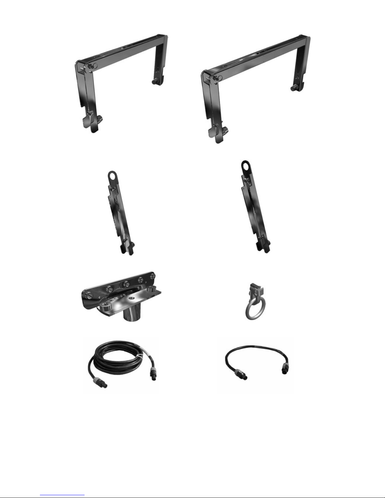
(7) ETR112XT
Adjustable U-Bracket for ceiling, wall or scaffold mounting of the 112XT in either horizontal or
vertical orientations
(8) CPL112XT
Coupling adapter bars used in conjunction with ETR112XT to array two 112XT enclosures
vertically with independent tilt adjustment for both enclosures
(9) ETR115XT
Adjustable U-Bracket for ceiling, wall or scaffold mounting of the 115XT in either horizontal or
vertical orientations
(10) CPL115XT
Coupling adapter bars used in conjunction with ETR115XT to array two 115XT enclosures
vertically with independent tilt adjustment for both enclosures
(11) XTLIFTBAR
Allows for single point rigging of 112XT or 115XT loudspeaker enclosures with 5 pick points
available for tilt adjustment
(12) PION 2
Double stud Aeroquip flytrack fitting-to-ring for permanent installation of 112XT or 115XT
enclosures or for use in conjunction with ETR112XT or ETR115XT as a safety attachment
LOUDSPEAKER CABLES
(13) F-CABLE (SP7, SP25)
Loudspeaker cable, 4 conductor, 4mm
2
conductor cross-section, 7 m (20 ft) or 25 m (80 ft)
length, equipped with 2 x Speakon connectors
(14) F-LINK CABLE (SP.7)
Loudspeaker link cable, 4 conductor, 4mm
2
conductor cross-section, 0.7 m (2 ft) length,
equipped with 2 x Speakon connectors (for paralleling XT enclosures).
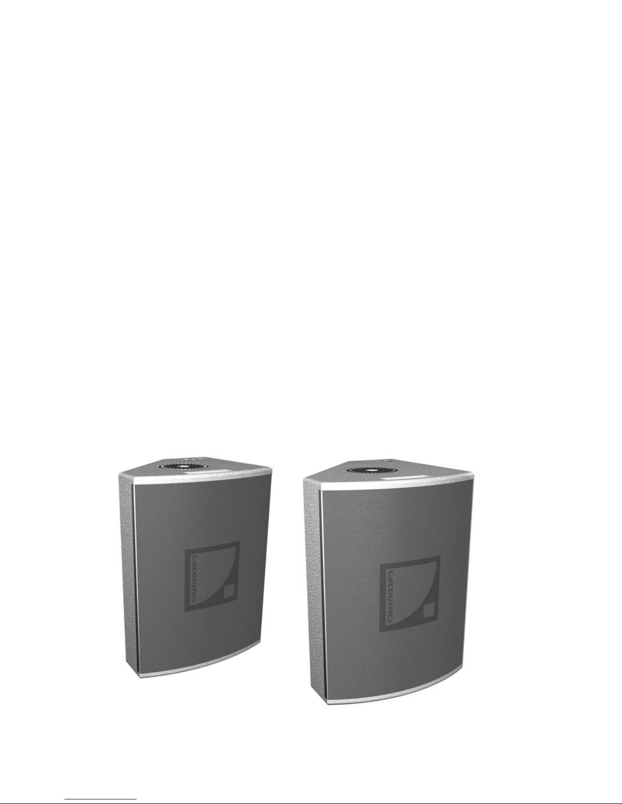
112XT
115XT
Page 9
L-ACOUSTICS XT Manual V1.1 2/11/2003 8
ETR112XT
ETR115XT
CPL112XT
CPL115XT
XTLIFTBAR
PION2
F-CABLE DO7
F-LINK CABLE DO.7
Figure 1: XT System Components
Page 10

L-ACOUSTICS XT Manual V1.1 2/11/2003 9
1.2 XT OVERVIEW
L-ACOUSTICS 112XT or 115XT loudspeaker enclosures are intended for distributed sound
reinforcement and can be used for either high performance touring or fixed installation. Both XT
loudspeaker enclosures feature highly-advanced coaxial components and rigging accessories while also
benefiting from the flexibility afforded by OEM digital presets.
The 112XT is an active 2-way loudspeaker containing a 1.4" exit compression driver that is directly
loaded by the 12" loudspeaker in a coaxial configuration while the 115XT features a 15” loudspeaker.
As discussed in the introduction, advantages of the coaxial approach include: single point source
radiation and excellent phase response, total wavefront coherency at all frequencies and axisymmetrical directivity that produces identical horizontal and vertical coverage. Coaxial design also
provides LF/HF superimposed dispersion characteristics that are free of polar lobing effects typical of
traditional horn and woofer combinations. The end result is natural, studio monitor level sound
quality, ideal for proximity use and perfectly matching semi-reverberant environments.
The 112XT or 115XT are ideal for distributed sound reinforcement and can also be used in medium
power front-of-house (FOH) applications for theatres, clubs, multi-purpose venues or corporate
events. Examples of distributed systems include delay rings for large-scale installations, surround
effects channels for theatre or multimedia, distributed reinforcement for sports venues, and delays for
speech reinforcement in convention centre ballrooms. Although optimized for single operation,
112XT or 115XT loudspeakers can be used in vertical arrays of two enclosures to enhance either SPL
or coverage. Due to their compact, wedge-shaped format and axi-symmetrical directivity, XT
enclosures also provide an exceptionally high performance floor monitor solution. When used with
the SB118 (or other L-ACOUSTICS subwoofers), XTs are also excellent for side fill and drum
monitoring applications.
OEM factory presets are available for approved digital processors, providing flexible solutions for a
wide variety of 2- and 3-way operating modes. For 2-way operation, three types of presets are
provided:
FRONT presets
are for standalone FOH operation (without subwoofers) where low and high
frequency shelving equalization provides a frequency response contour suitable for music
applications.
FILL presets
provide nominally flat response for use in speech reinforcement and classical music
applications or when XT enclosures are used as a close proximity fill enclosure.
Both FRONT and FILL presets are derived under freefield measurement conditions.
MONITOR presets
include additional low frequency equalization to account for half-space
loading conditions and are intended for floor monitoring applications or fixed installations where
the XT is wall- or ceiling-mounted.
MONITOR presets are derived under half-space measurement conditions.
A variety of 3-way presets are provided for use of the 112XT or 115XT with SB115, SB118, SB218 or
dV-SUB subwoofers. Standard 3W presets
utilize a complimentary 100 Hz crossover point for the XT
and its companion subwoofer and are recommended for closely coupled applications. Alternatively,
when XT enclosures are flown and subwoofers are ground stacked, 3WX presets
can be employed
where an 80 Hz low pass filter is applied to the subwoofers and 112XT or 115XT low frequency
response extends to 55 or 50 Hz, respectively.
Pole mount sockets and side-mounted fly track sections are included as standard on XT enclosures
and optional rigging accessories include an adjustable U-bracket for ceiling, wall or scaffold mounting
(vertical or horizontal orientations), coupling adapter bars for vertical coupling of two XT enclosures
(independent tilt adjustment for each enclosure) and the XTLIFTBAR accessory for single point rigging
(5 pick points available allowing for tilt adjustment).
Page 11
L-ACOUSTICS XT Manual V1.1 2/11/2003 10
1.3 112XT SPECIFICATIONS
The 112XT is an active, two-way, coaxial full range loudspeaker containing one direct radiating, bass
reflex-loaded, 12 inch low frequency transducer and one 1.4 inch exit, 3 inch voice coil diameter,
titanium alloy diaphragm compression driver. As a full range system, the frequency response is 65 Hz
to 18 kHz with less than ± 3 dB variation and the usable bandwidth is 55 Hz to 18 kHz (-10 dB).
The cone body of the low frequency component provides pattern control loading of the compression
driver and yields a 90-degree (± 20 degrees) conical dispersion pattern that is axi-symmetrical. The
crossover point between low and high frequency components is 1 kHz with 24 dB per octave
Linkwitz-Riley characteristics. Long term power handling is 290 Wrms for the low section and 135
Wrms for the high section at a nominal 8 ohm impedance. Connection to the loudspeaker is made via
two parallel 4-pin Neutrik Speakon connectors.
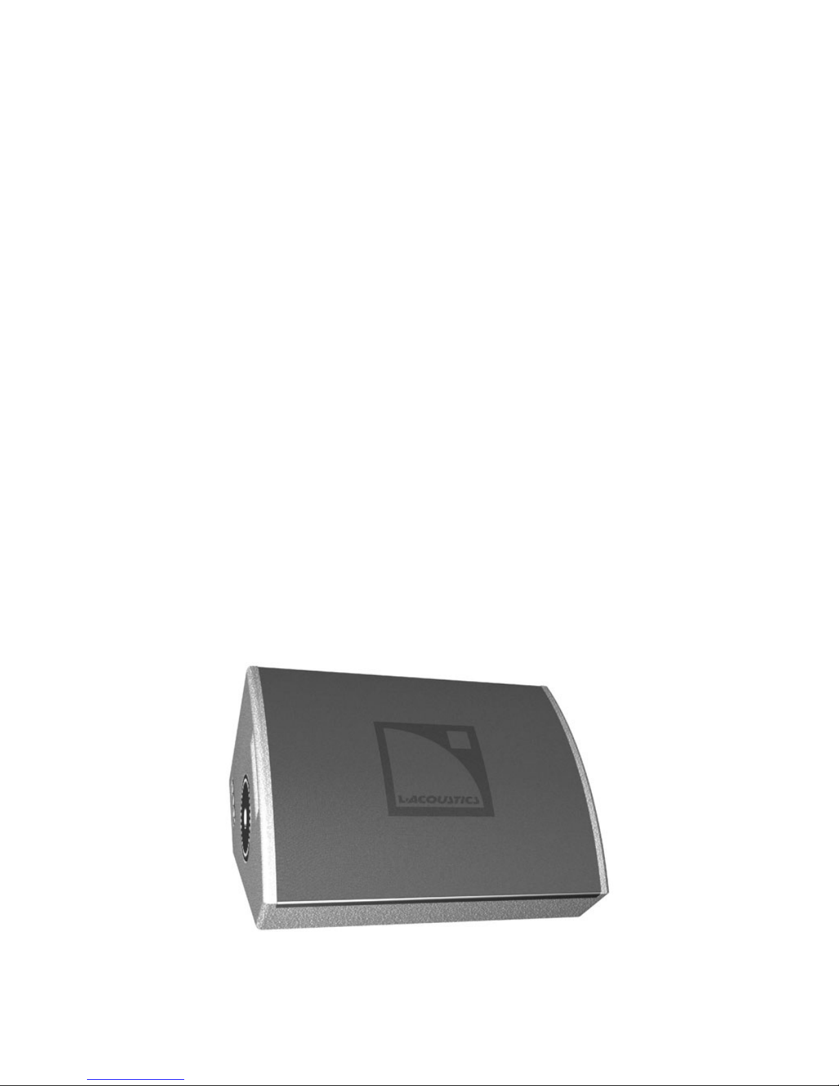
The 112XT has a truncated wedge shape with a curved front profile. Dimensions are 54 cm (21.3 in)
high, 41 cm (16.1 in) wide at the front of the enclosure, 16.5 cm (6.5 in) wide at the rear of the
enclosure and 37.5 cm (14.8 in) deep. When used on its rear side, the front baffle of the enclosure is
oriented at a 45 degree angle with respect to vertical, allowing the enclosure to be used as a floor
monitor. Enclosure weight is 27 kg (59.5 lbs).
Cabinet construction consists of 30 mm (1.18 in) and 18 mm (0.70 in) Baltic birch plywood with
internal steel bracing and joints that are sealed, screwed and rabbeted. The finish is maroon-gray high
resilient paint. The front of the enclosure is protected by a black powder-coated, 1.5 mm (0.06 in)
thick steel grill that is covered with 10 mm (0.4 in) thick acoustically transparent open cell foam.
The 112XT has two side-recessed flytrack sections and 36 mm (1.42 in) diameter pole mount sockets
mounted on the top and bottom sides. Pole mount sockets function with the ETR112XT U-bracket
accessory for rigging the enclosure in either horizontal or vertical orientations, providing angular
adjustment with 10 degree resolution. Two CPL112XT coupling adapter bars can be used in
conjunction with the ETR112XT U-bracket, allowing two 112XT enclosures to be flown vertically
while providing independent tilt adjustment for each enclosure. The XTLIFTBAR accessory functions
with either of the pole mount sockets and provides five attachment points for rigging purposes.
The 112XT loudspeaker is used with an approved digital processor with OEM factory presets for
active 2-way operation or 3-way operation in conjunction with additional subwoofers (L-ACOUSTICS
SB115, SB118, SB218 or dV-SUB).
Figure 2: 112XT Enclosure
Page 12
L-ACOUSTICS XT Manual V1.1 2/11/2003 11
1.4 115XT SPECIFICATIONS
The 115XT is an active, two-way, coaxial full range loudspeaker containing one direct radiating, bass
reflex-loaded, 15 inch low frequency transducer and one 1.4 inch exit, 3 inch voice coil diameter,
titanium alloy diaphragm, neodymium compression driver. As a full range system, frequency response
is 60 Hz to 18 kHz with less than ± 3 dB variation and the usable bandwidth is 50 Hz to 18 kHz (-10
dB).
The cone body of the low frequency component provides pattern control loading of the compression
driver and yields an 80-degree (± 20 degree) conical dispersion pattern that is axi-symmetrical. The
crossover point between low and high frequency components is 1 kHz with 24 dB per octave
Linkwitz-Riley characteristics. Long term power handling is 250 Wrms for the low section and 85
Wrms for the high section at a nominal 8 ohm impedance. Connection to the loudspeaker is made via
two parallel 4-pin Neutrik Speakon connectors.
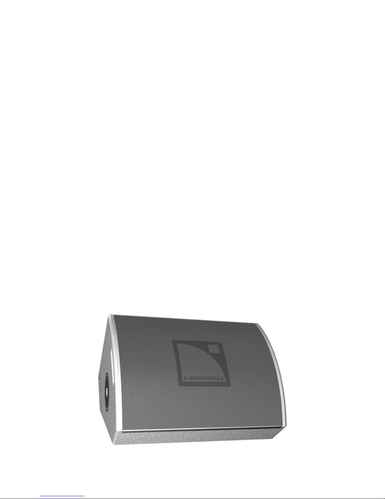
The 115XT enclosure has a truncated wedge shape with a curved front profile. Dimensions are 58 cm
(22.8 in) high, 44 cm (17.3 in) wide at the front of the enclosure, 16.7 cm (6.6 in) wide at the rear of
the enclosure and 47.5 cm (18.7 in) deep. When used on its rear side, the front baffle of the 115XT is
oriented at a 41 degree angle with respect to vertical, allowing the enclosure to be used as a floor
monitor. Enclosure weight is 29.5 kg (65.0 lbs).
Cabinet construction consists of 30 mm (1.18 in) and 18 mm (0.70 in) Baltic birch plywood with
internal steel bracing and joints that are sealed, screwed and rabbeted. The finish is maroon-gray high
resilient paint. The front of the enclosure is protected by a black powder-coated, 1.5 mm (0.06 in)
thick steel grill that is covered with 10 mm (0.39 in) thick acoustically transparent open cell foam.
The 115XT has two side-recessed flytrack sections and 36 mm (1.42 in) diameter pole mount sockets
mounted on the top and bottom sides. Pole mount sockets function with the ETR115XT U-bracket
accessory for rigging the enclosure in either horizontal or vertical orientations, providing angular
adjustment with 10 degree resolution. Two CPL115XT coupling adapter bars can also be used in
conjunction with the ETR115XT U-bracket, allowing two 115XT enclosures to be flown vertically
while providing independent tilt adjustment for each enclosure. The XTLIFTBAR accessory functions
with either of the pole mount sockets and provides five attachment points for rigging purposes.
The 115XT loudspeaker is used with an approved digital processor with OEM factory presets for
active 2-way operation or 3-way operation in conjunction with additional subwoofers (L-ACOUSTICS
SB115, SB118, SB218 or dV-SUB).
Figure 3: 115XT Enclosure
Page 13

L-ACOUSTICS XT Manual V1.1 2/11/2003 12
2. POWERING XT
It is important that power amplifiers with sufficient power are used to power the 112XT or 115XT
since headroom is less likely to damage loudspeaker components than clipping. Apart from normal
standards regarding construction, protection, cooling and damping factor that are expected of any
professional sound reinforcement amplifier, the XT system has been calibrated to be used with
amplifiers with the following specifications:
GAIN STRUCTURE
All amplifiers should have 32 dB gain for all sections (sub, low and high). The limiter thresholds and
output channel gains of OEM digital crossover presets have been adjusted to be used with amplifiers
having 32 dB gain
.
LIMITERS
Peak limiters on all amplifier outputs with soft clipping characteristics; attack time less than 3msec
COOLING
Temperature speed-controlled fan recommended
In practice, L-ACOUSTICS specifies power amplifiers with output power equivalent to twice the RMS
power handling for the low section and equivalent to the peak power handling for the high section.
These requirements typically allow the same amplifier to be used for both sections since the drive
level for the HF section is attenuated relative to the LF section to account for efficiency differences
(i.e., full continuous power will never be delivered to the HF section due to this attenuation). When
the same amplifier is used for the HF section, the extra available power then translates into headroom
for improved high frequency transient response.
Sections 2.1 and 2.2 give a summary of rms and peak power handling along with recommended power
amplifier output specifications for operation of single 112XT or 115XT enclosures or multiple XT
enclosures in parallel.
2.1 POWERING 112XT
Continuous (rms) and peak power handling ratings for the 112XT are as follows:
LF Section: 48 volts rms long term (pink noise with 6 dB crest factor)
290 Watts (continuous), 1160 Watts (peak) at 8 ohms
HF Section: 33 volts rms long term (pink noise with 6 dB crest factor)
135 Watts (continuous), 540 Watts (peak) at 8 ohms
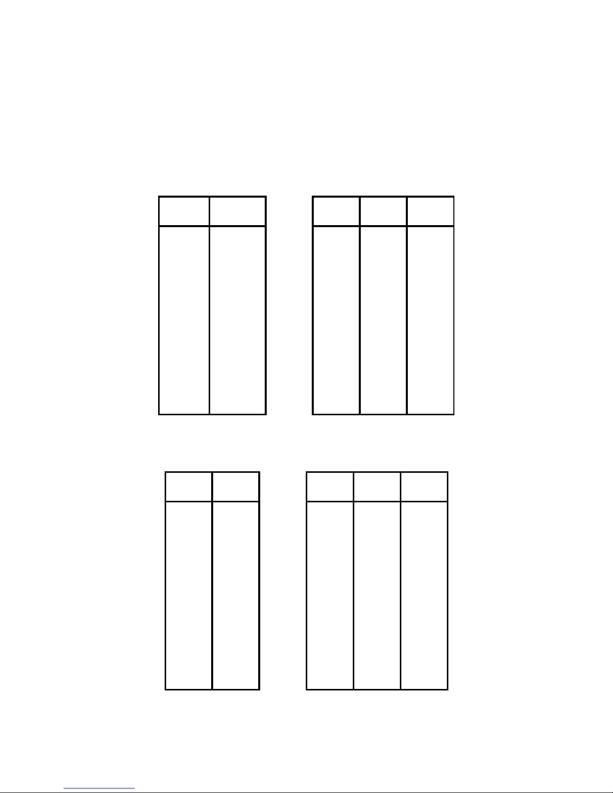
Table 1: Load and Power Ratings for 112XT
112XT ENCLOS URE RATINGS
ONE 112XT TWO 112XT THREE 112XT FOUR 112XT
SECTION LOAD RMS PEAK REC'D LOAD RMS PEAK REC'D LOAD RMS PEAK REC'D LOAD RMS PEAK REC'D
LOW 8 290 1160
580
4 580 2320
1160
2.7 870.0 3480
1740
2 1160 4640
2320
HIGH 8 135 540
540
4 270 1080
1080
2.7 400.0 1600
1600
2 540 2160
2160
For amplifying 2 112XT in parallel, the recommended amplifier specifications are:
* LOW Amplifier Output Power: 1160 W into 4 ohms
* HIGH Amplifier Output Power: 1080 W into 4 ohms
For amplifying 3 112XT in parallel, the recommended amplifier specifications are:
* LOW Amplifier Output Power: 1740 W into 2.7 ohms
* HIGH Amplifier Output Power: 1600 W into 2.7 ohms
Page 14
L-ACOUSTICS XT Manual V1.1 2/11/2003 13
For amplifying 4 112XT in parallel, the recommended amplifier specifications are:
* LOW Amplifier Output Power: 2320 W into 2 ohms
* HIGH Amplifier Output Power: 2160 W into 2 ohms
Based on these specifications, recommended L-ACOUSTICS LA power amplifier specifications and
MLS switch settings are summarized in Tables 2 and 3. In these tables, boldface settings indicate a
good power match based on the recommended power amplifier specification.
Table 2: Recommended power amplification and MLS switch settings for 112XT low section
112XT LOW SECTION AMPLIFIER OUTPUT POWER
REC'D POWER (MLS SETTING)
LOAD POWER LA 17a LA 24a LA 48a
(ohms) (W)
2 2320 do not use do not use
2400
(-2 dB)
2.7 1740 1080 1635
2130
(0 dB) (0 dB)
(-2 dB)
4 1160 840
1300 1600
(0 dB)
(-2 dB) (-2 dB)
8 580 430
700 820
(0 dB)
(-2 dB) (-2 dB)
Table 3: Recommended power amplification and MLS switch settings for 112XT high section
112XT HI SECTION AMPLIFIER OUTPUT POWER
REC'D POWER (MLS SETTING)
LOAD REC'D LA 17a LA 24a LA 48a
(ohms) POWER
2 2160 do not use do not use 2000
(-4 dB)
2.7 1600 1080
1635 1665
(0 dB)
(0 dB) (-4 dB)
4 1080 840
1300
1000
(0 dB)
(-2 dB)
(-4 dB)
8 540 430
700
520
(0 dB)
(-2 dB)
(-4 dB)
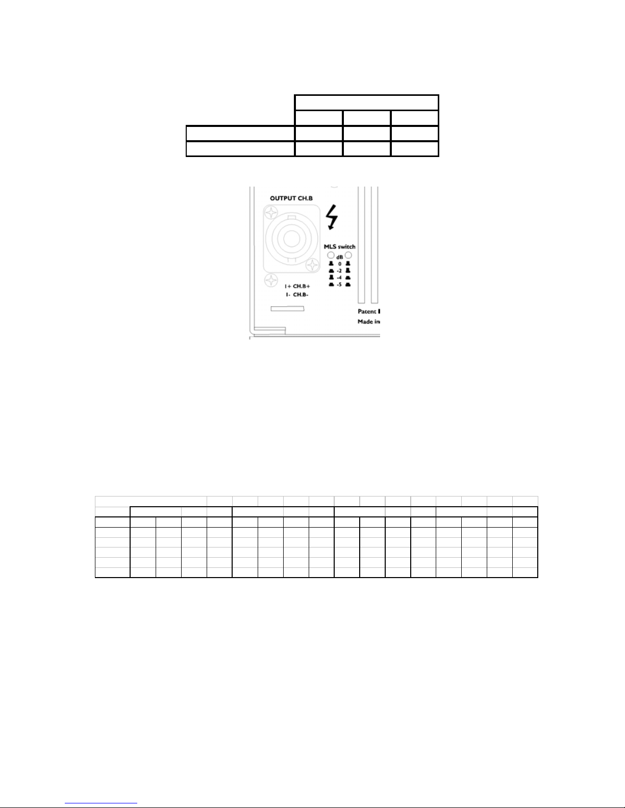
L-ACOUSTICS LA amplifier MLS switch settings for powering the 112XT are summarized in Table 4
and Figure 4 shows the location of MLS switches on the LA24a and LA48a rear panel.
Page 15
L-ACOUSTICS XT Manual V1.1 2/11/2003 14
Table 4: Recommended MLS switch settings for powering 112XT
MLS SWITCH SETTING
LA17a LA24a LA48a
112XT LO SECTION 0 dB -2 dB -2 dB
112XT HI SECTION 0 dB -2 dB -4 dB
Figure 4: MLS switches on the rear panel of L-ACOUSTICS LA24a, LA48a amplifiers
2.2 POWERING 115XT
Continuous (rms) and peak power handling ratings for the 115XT are as follows:
LF Section: 45 volts rms long term (pink noise with 6 dB crest factor)
250 Watts (continuous), 1000 Watts (peak) at 8 ohms
HF Section: 26 volts rms long term (pink noise with 6 dB crest factor)
85 Watts (continuous), 350 Watts (peak) at 8 ohms
Table 5: Load and Power Ratings for 115XT
115XT ENCLOSURE RATINGS
ONE 115XT TWO 115XT THREE 115XT FOUR 115XT
SECTION LOAD RM S PEAK REC'D L OAD RM S PEAK REC'D L OAD RM S PEAK REC'D L OAD RM S PEAK REC'D
LOW 8 250 1000
500
4 500 2000
1000
2.7 750.0 3000
1500
210004000
2000
HIGH 8 85 350
350
4 170 700
700
2.7 250.0 1000
1000
2 350 1400
1400
For amplifying 2 115XT in parallel, the recommended amplifier specifications are:
* LOW Amplifier Output Power: 1000 W into 4 ohms
* HIGH Amplifier Output Power: 700 W into 4 ohms
For amplifying 3 115XT in parallel, the recommended amplifier specifications are:
* LOW Amplifier Output Power: 1500 W into 2.7 ohms
* HIGH Amplifier Output Power: 1000 W into 2.7 ohms
For amplifying 4 115XT in parallel, the recommended amplifier specifications are:
* LOW Amplifier Output Power: 2000 W into 2 ohms
* HIGH Amplifier Output Power: 1400 W into 2 ohms
Page 16
L-ACOUSTICS XT Manual V1.1 2/11/2003 15
Based on these specifications, recommended L-ACOUSTICS LA power amplifier specifications and
MLS switch settings are summarized below in Tables 6 and 7.
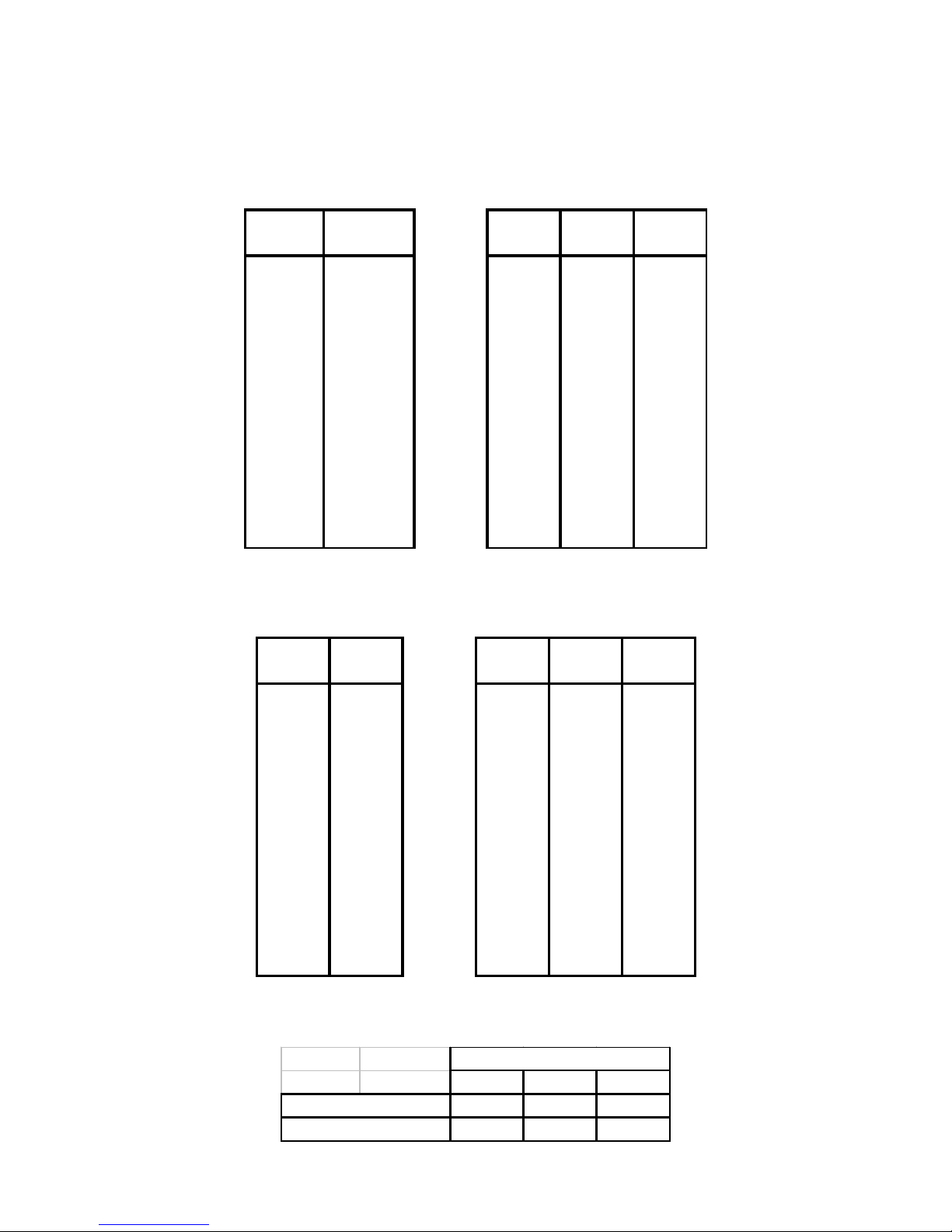
Table 6: Recommended power amplification and MLS switch settings for 115XT low section
115XT LOW SECTION AMPLIFIER OUTPUT POWER
REC'D POWER (MLS SETTING)
LOAD POWER LA 17a LA 24a LA 48a
(ohms) (W)
2 2000 do not use do not use
2000
(-4 dB)
2.7 1500 1080
1635 1665
(0 dB)
(0 dB) (-4 dB)
4 1000 840
1300 1000
(0 dB)
(-2 dB) (-4 dB)
8 500 430
700 520
(0 dB)
(-2 dB) (-4 dB)
Table 7: Recommended power amplification and MLS switch settings for 115XT high section
115XT HI SECTION AMPLIFIER OUTPUT POWER
REC'D POWER (MLS SETTING)
LOAD REC'D LA 17a LA 24a LA 48a
(ohms) POWER
2 1400 1200
1400 1660
(0 dB)
(-4 dB) (-5 dB)
2.7 1000
1080 1180 1380
(0 dB) (-4 dB) (-5 dB)
4 700
840 750 830
(0 dB) (-4 dB) (-5 dB)
8 350
430 400 430
(0 dB) (-4 dB) (-5 dB)
MLS switch settings for powering the 115XT are summarized in Table 8.
Table 8: Recommended MLS switch settings for powering 115XT
MLS SWITCH SETTING
LA17a LA24a LA48a
115XT LO SECTION 0 dB -2 dB -4 dB
115XT HI SECTION 0 dB -4 dB -5 dB
Page 17
L-ACOUSTICS XT Manual V1.1 2/11/2003 16
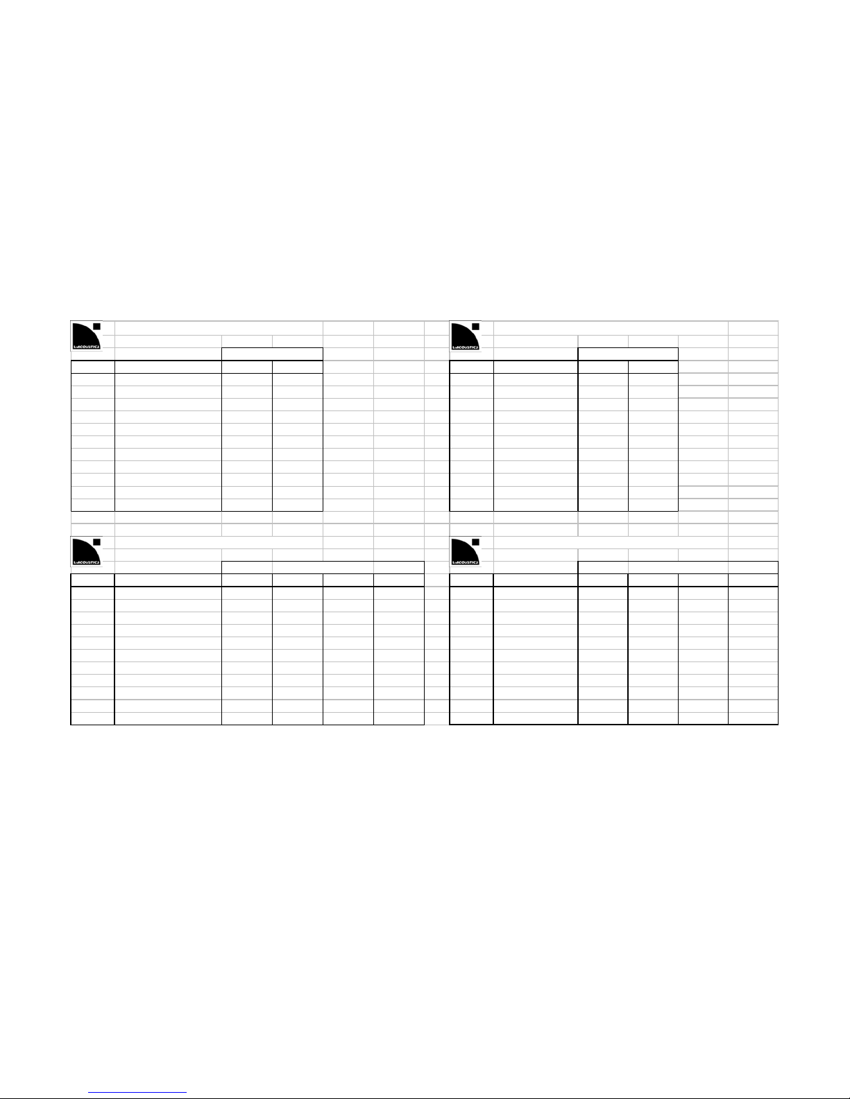
L-ACOUSTICS LA 15a POWER MATRIX L-ACOUSTICS LA 17a POWER MATRIX
MLS SWITCH SETTING MLS SWITCH SETTING
LOAD CON FIGURATIO N -3 dB 0 dB LOAD CON FIGURATIO N -3 dB 0 dB
16 ohms Quad (4 channel) 95 200 16 ohms Stereo (2 channel) 110 215
8 ohms Quad (4 channel) 200 370 8 ohms Stereo (2 channel) 220 430
4 ohms Quad (4 channel) 380 600 4 ohms Stereo (2 channel) 430 840
2.7 ohms Quad (4 channel) 460 2.7 ohms Stereo ( 2 channel) 720 1080
2 ohms Quad (4 channel) 500 2 ohms Stereo (2 channel) 870 1200
L-ACOUSTICS LA 24a POWER MATRIX L-ACOUSTICS LA 48a POWER MATRIX
MLS SWITCH SETTING MLS SWITCH SETTING
LOAD CON FIGURATIO N -5 dB -4 dB -2 dB 0 dB LOAD CON FIGURATIO N -5 dB -4 dB -2 dB 0 dB
16 ohms Stereo (2 channel) 160 200 340 520 16 ohms Stereo (2 channel) 220 260 410 650
8 ohms Stereo (2 channel) 300 400 700 1100 8 ohms Stereo (2 channel) 430 520 820 1300
4 ohms Stereo (2 channel) 600 750 1300 1500 4 ohms Ster eo (2 channel) 830 1000 1600 2300
2.7 ohms Stereo ( 2 channel) 1000 1180 1465 1635 2.7 ohms Stereo (2 channel) 1380 1665 2130 2700
2 ohms Stereo (2 channel) 1200 1400 1550 1700 2 ohms Stereo (2 channel) 1660 2000 2400 2900
Table 9: Output Power Ratings and MLS Switch Settings for L-ACOUSTICS LAa Amplifiers
Page 18

L-ACOUSTICS XT Manual V1.1 2/11/2003 17
2.3 CONNECTORS AND CABLES
112XT and 115XT are supplied with dual NL4 Speakon connectors. The two Speakon connectors are
internally wired in parallel, allowing for loop through connection and parallel operation of multiple XT
enclosures. Speakon connectors are wired as follows:
1+ = LF+
1 - = LF 2+ = HF+
2 - = HF –
In order to preserve high damping factor (essential to the sonic qualities of the system and to prevent
overshoot of cone displacement which can result in mechanical damage), it is desirable to keep
loudspeaker cables as short as possible and with a gauge offering low resistance per unit length. The
following chart provides information regarding the minimum wire cross-section versus length:
Table 10: Maximum Recommended Length for Damping Factor > 20
Cross Section Gauge 8 ohms 4 ohms
Metric (mm2) Imperial Metric Imperial Metric Imperial
2.5 13 30 m 100 ft 15 m 45 ft
4 11 50 m 150 ft 25 m 75 ft
6 8 75 m 225 ft 37 m 110 ft
10 6 120 m 360 ft 60 m 180 ft
As standard, L-ACOUSTICS F-CABLE (SP7, SP25) and F-LINK CABLE (SP.7) loudspeaker cables are 4
conductor cables with 4 mm
2
conductor cross-section (11 gauge). SP25 cables can be used for 25
meter cable runs to power a 4 ohm load (2 x 112XT or 115XT enclosures in parallel) while
maintaining a damping factor greater than 20.
3. XT CONTROL AND PROCESSING
A digital processor is specified for use with XT enclosures in order to provide the following functions:
crossover filtering, component time alignment, corrective component equalization, system protection
and system equalization. OEM factory presets are provided for a number of approved digital
processors including: BSS FDS-366 Omnidrive Compact Plus, BSS FDS-334 Minidrive, BSS FDS-336
Minidrive, XTA DP224 and XTA DP226. All presets (except for Minidrive) are distributed via
PCMCIA card and can also be downloaded from the L-ACOUSTICS website (www.l-acoustics.com
).
Since the XTA DP226 is a 2 input by 6 output unit, the DP224 is 2 x 4, the FDS-334 is 2 x 4, the FDS336 is 2 x 6 and the FDS-366 is 3 x 6, exact internal wiring of your FOH drive rack and digital
processor channel assignments will vary depending on the selected processor and the application.
Carefully consider your flexibility requirements before selecting the type of processor to specify.
NOTE: ALWAYS REFER TO THE PRESET DESCRIPTION SHEET FOR YOUR PROCESSOR WHEN
SELECTING PRESETS AND CONFIGURING YOUR DRIVE RACK.
Page 19

L-ACOUSTICS XT Manual V1.1 2/11/2003 18
3.1 GENERAL DESCRIPTION OF XT PRESETS
For 2-way operation, three types of presets are provided:
FRONT presets
are for standalone FOH operation (without subwoofers) where low and high
frequency shelving equalization provides a frequency response contour suitable for music
applications.
FILL presets
provide nominally flat response for use in speech reinforcement and classical music
applications or when XT enclosures are used as a close proximity fill enclosure.
FRONT and FILL presets are derived under freefield measurement conditions.
MONITOR presets
include additional low frequency equalization to account for half-space
loading conditions and are intended for floor monitoring applications or fixed installations where
the XT is wall- or ceiling-mounted.
MONITOR presets are derived under half space measurement conditions.
A variety of 3-way presets are provided for use of 112XT or 115XT loudspeaker enclosures with
SB115, SB118, SB218 or dV-SUB subwoofers. Standard 3W presets
utilize a complimentary 100 Hz
crossover point for the XT and its companion subwoofer and are recommended for closely coupled
applications. Alternatively, when XT enclosures are flown and subwoofers are ground stacked, 3WX
presets can be employed where an 80 Hz low pass filter is applied to the subwoofers and 112XT or
115XT low frequency response extends to 55 or 50 Hz, respectively.
3.2 XT PRESET POLICY
According to L-ACOUSTICS policy, key parameters are software-protected and preset data or
passwords are not available in order to preserve quality control, confidentiality and to maintain the
integrity of L-ACOUSTICS system presets. Restricting access to presets is in no way meant to restrict
flexibility or the creative process – on the contrary, software-protected presets are intended to
enhance creativity by ensuring quality control and repeatability.
Extensive engineering and real world testing goes into determining optimum presets – detailed polar
measurements and weighted spatial averaging are used to determine component equalization, time
alignment, crossover points and crossover filter slopes, for example. As a result, L-ACOUSTICS
presets give the user an optimum starting point – system tuning should be done using band
attenuation, subwoofer time alignment and system equalization using input section parametric filters –
not by altering presets for the following reason:
Without proper instrumentation and spatial averaging, adjustments made at one location (e.g. the mix
position) are not optimum at all other locations within the defined coverage region of the system.
When made by ear, such adjustments are often misguided – the user may be in a local room mode
(low frequency pressure maximum or minimum) and/or may be hearing a cancellation or addition due
to crossover misalignment that sounds good at that specific location but what about all others?
Meanwhile, the same result could have been achieved while preserving the power response of the
system by using the correct crossover preset and a simple equalization cut or correct time alignment
of subwoofers.
Preset libraries are distributed via PCMCIA Card which are available from L-ACOUSTICS
headquarters in France , L-ACOUSTICS US, L-ACOUSTICS UK or your L-ACOUSTICS distributor.
Preset libraries and upgrades can also be downloaded from www.l-acoustics.com
.
Page 20
L-ACOUSTICS XT Manual V1.1 2/11/2003 19
3.3 GUIDELINES REGARDING SYSTEM PROTECTION
As standard, limit thresholds for XTA and BSS Processors are initially set at 3 dBu above the RMS
power handling for both low and high sections of the 112XT and 115XT as follows:
112XT low section : +6 dBu
112XT high section : +3 dBu
115XT low section : +6 dBu
115XT high section : +2 dBu
Amplifier input sensitivities (0 dB MLS switch setting) are as follows:
LA17a : +5.5 dBu
LA24a : +7.7 dBu
LA48a : +9.5 dBu
For the 112XT and 115XT low section, the +6 dBu limit threshold corresponds to 3 dBu above the
RMS power handling of the low section as well as the input sensitivity of the L-ACOUSTICS LA17a
(+5.5 dBu) and LA 24a (+7.7 dBu) so that system protection is performed by a combination of the
clip limiting circuits of the amplifier and the output channel limiters of the digital signal processor.
Note: L-ACOUSTICS recommends that LA power amplifier clip limiters be engaged at all times (CLIP switch
depressed in the “IN” position).
L-ACOUSTICS LA amplifier clip limiters are sonically transparent and function by monitoring the
output signal and comparing the distortion produced between the input and output of the amplifier. If
the distortion exceeds 1% THD for any reason (voltage or current clipping), the limiter reduces the
input signal proportionally (2 msec attack, 150 msec release). Under normal operation, clip limiting is
inaudible and L-ACOUSTICS recommends leaving the Channel A and B clip limiters switched ''on''
(rear panel button depressed) at all times.
As shown in Sections 2.1 and 2.2, additional protection can be obtained by using the following MLS
switch settings for power matching of the amplifier output to the power handling capacity of the XT
low and high sections:
MLS SWITCH SETTING
LA17a LA24a LA48a
112XT LO SECTION 0 dB -2 dB -2 dB
112XT HI SECTION 0 dB -2 dB -4 dB
MLS SWITCH SETTING
LA17a LA24a LA48a
115XT LO SECTION 0 dB -2 dB -4 dB
115XT HI SECTION 0 dB -4 dB -5 dB
For the 112XT and 115XT high section, the +3 dBu (112XT) or +2 dBu (115XT) limit thresholds
correspond to 3 dBu above the RMS power handling of the high section and system protection is
performed by the limiting circuitry of the digital signal processor.
Example: For the 112XT, the high section limit threshold is set to 3 dBu below the peak power
handling in order to provide secure operation, i.e, the RMS power handling is 135 W, peak power
handling is 540 W and assuming 32 dB amplifier gain, these power ratings correspond to limit
thresholds of 0 dBu (135 W) and +6 dBu (540 W). As standard, the 112XT HF limiter threshold is set
to +3 dBu (3 dB less than the peak power handling).
Page 21

L-ACOUSTICS XT Manual V1.1 2/11/2003 20
Standard HF limiter thresholds for the 112XT and 115XT are suitable for most applications however
the following adjustments can be made depending on the program content:
1) classical music - lots of transients, low RMS signal content
increase standard HF limit threshold by 3 dB to correspond to the peak power handling
(for example, 112XT HF limit threshold: +3 dBu -> +6 dBu)
2) rave/techno music - high RMS signal content, long duration
decrease standard HF limit threshold by 3 dB to correspond to the RMS power handling
(for example, 112XT HF limit threshold: +3 dBu -> 0 dBu)
NOTE: Setting limit thresholds to the amplifier input sensitivity (or the rated power handling of the section
being driven) is important since this calibrates the output meter display of the crossover to correspond to
either the amplifier clip point or the rated power handling. This gives the system operator a direct visual
indication as to how hard the system is being operated.
3.4 XT PRESET LIBRARIES
As described in Section 3.2, three types of 2-way presets for 112XT and 115XT are provided
(FRONT, FILL and MONITOR) while two types of 3-way presets are available for the use of
XT enclosures with L-ACOUSTICS SB115, SB118, SB218 or dV-SUB subwoofers (3W and
3WX).
All 2-way presets are configured in stereo 3-way mode, i.e., channel A and B Low/High
outputs are on output channels 2 / 3 and 5 / 6, respectively. This means that drive racks do
not require recabling when changing from 3-way to 2-way presets. In addition, for these 2way presets, channels 1 and 4 are unlocked and available for programming of passive fill
loudspeakers, subwoofers or, alternatively, for monitoring input equalization when using the
SMAART or SPECTRAFOO measurement systems.
Note: for BSS FDS-366, 3 x 2-way presets are provided in memory locations 37-46. This channel
configuration is recommended for 3 mix floor monitoring or Left/Centre/Right (LCR) applications.
Please refer to the appropriate Preset Description Sheet (excel .XLS files) to assist in
selecting the appropriate preset and as a reference for properly configuring crossover output
channels for your drive rack or signal distribution system.
Complete Preset Description Sheet excel files are available for download from
www.l-
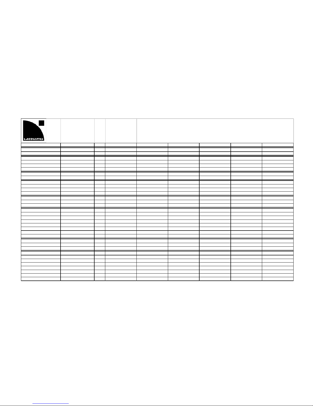
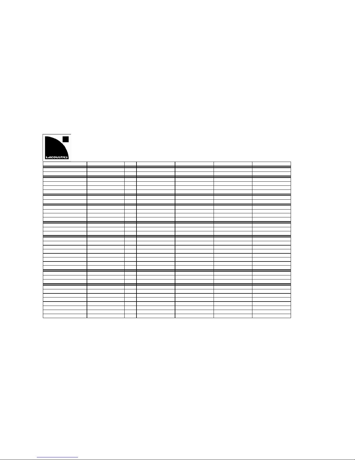
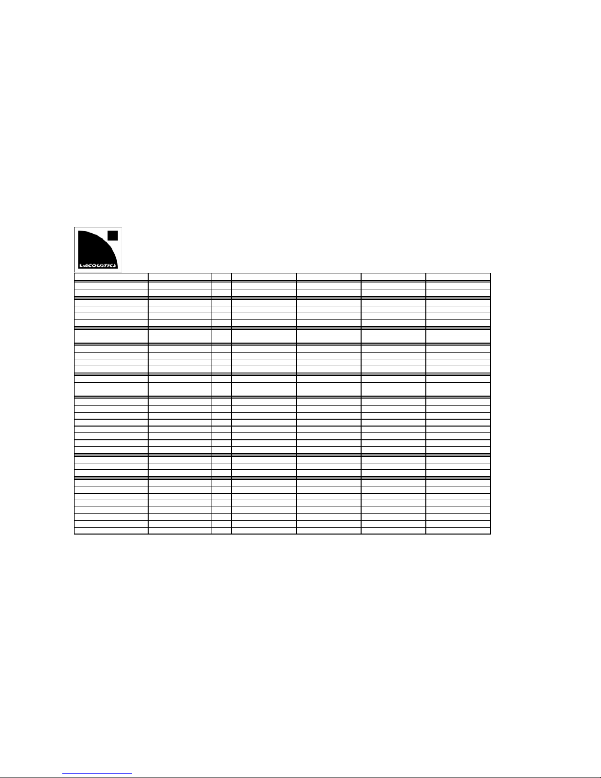
acoustics.com along with preset library data. As a quick reference, Figures 5-9 give channel
assignments for XTA DP226, DP224 and BSS 334, 336, 366 respectively.
Page 22
L-ACOUSTICS XT Manual V1.1 2/11/2003 21
L-ACOUSTICS V7 0902 PRESETS for XTA DP 226
PRESET NA ME PGM TYP E MEM OUT 1 (Sour ce) OUT 2 (Sou rce) OUT 3 (So urce) OUT 4 (So urce) OUT 5 (S ource) OUT 6 (S ource)
ARCS 2W LO 3-way stereo 10 FU LL (A) ARCS LOW (A) ARCS HI (A) FULL (B) ARCS LOW (B) ARCS HI (B)
ARCS 2W HI 3-way stereo 11 FU LL (A) ARCS LOW (A) ARCS HI (A) FULL (B) ARCS LOW (B) ARCS HI (B)
ARCS 3W SB218 LO 3-wa y stereo 12 SB21 8 (A) A RCS LOW (A) ARC S HI (A) SB2 18 (B) ARCS LOW ( B) ARCS HI ( B)
ARCS 3W SB218 HI 3-wa y stereo 13 SB21 8 (A) A RCS LOW (A) ARC S HI (A) SB218 (B) ARCS LO W (B) ARCS H I (B)
ARCS 3W dV-SUB LO 3-wa y stereo 14 dV-SUB (A) ARCS LOW (A) A RCS HI (A) dV-SU B (B) ARCS LO W (B) ARCS H I (B)
ARCS 3W dV-SUB HI 3-wa y stereo 15 dV-SUB ( A) ARCS LOW (A) A RCS HI (A) dV-SU B (B) ARCS LO W (B) ARCS H I (B)
115FM 2W COUPLED 3-way stereo (not linked) 16 FULL (A) 115FM LOW (A) 115FM HI (A) FULL (B) 115FM LOW (B) 115 FM HI (B)
115FM 2WX SINGLE 3-way stereo (not linke d) 17 FULL (A) 115FM LO W (A) 115FM HI (A) FULL (B) 115FM LOW (B) 115FM HI ( B)
115FM 3W SB115 3-way stereo 18 SB115 (A) 115FM L OW (A) 115FM HI (A) SB115 (B) 115FM LO W (B) 115FM HI (B)
115FM 3W SB118 3-way stereo 19 SB118 (A) 115FM L OW (A) 115FM HI (A) SB118 (B) 115FM LO W (B) 115FM HI (B)
115FM 3W SB218 3-way stereo 20 SB218 (A) 115FM L OW (A) 115FM HI (A) SB218 (B) 115FM LO W (B) 115FM HI (B)
115FM 3W dV-SUB 3-way stereo 21 dV-SUB (A) 115FM L OW (A) 115FM HI (A) dV-SUB (B) 115FM LOW (B) 115FM HI (B)
112XT 2W FILL 3-way stereo 22
FULL (A)
112XT LOW (A) 112XT HI (A )
FULL (B)
112XT LOW (B) 112XT HI (B)
112XT 2W FRONT 3-way stereo 23
FULL (A)
112XT LOW (A) 112XT HI (A )
FULL (B)
112XT LOW (B) 112XT HI (B)
112XT 2W MONITOR 3-way stereo (not linked) 24
FULL (A)
112XT LOW (A) 112XT HI (A )
FULL (B)
112XT LOW (B) 112XT HI (B)
112XT 3W SB115 3-way stereo 25 SB115 (A) 112XT LOW (A) 112XT HI (A) SB115 (B) 112XT LOW (B) 112XT HI (B)
112XT 3WX SB115 3-way stereo 26 SB115 (A) 112XT LOW (A) 112XT HI (A) SB115 (B) 112XT LOW (B) 112XT HI (B)
112XT 3W SB118 3-way stereo 27 SB118 (A) 112XT LOW (A) 112XT HI (A) SB118 (B) 112XT LOW (B) 112XT HI (B)
112XT 3WX SB118 3-way stereo 28 SB118 (A) 112XT LOW (A) 112XT HI (A) SB118 (B) 112XT LOW (B) 112XT HI (B)
112XT 3W SB218 3-way stereo 29 SB218 (A) 112XT LOW (A) 112XT HI (A) SB218 (B) 112XT LOW (B) 112XT HI (B)
112XT 3WX SB218 3-way stereo 30 SB218 (A) 112XT LOW (A) 112XT HI (A) SB218 (B) 112XT LOW (B) 112XT HI (B)
112XT 3W dV-SUB 3-way stereo 31 dV-SUB (A) 112XT LOW (A) 112XT H I (A) dV-SUB (B) 112XT LOW (B) 112XT HI (B)
112XT 3WX dV-SUB 3-way stereo 32 dV-SUB (A) 112XT LO W (A) 112XT HI (A) dV-SUB (B) 112XT LOW (B) 112XT HI (B)
115XT 2W FILL 3-way stereo 33
FULL (A)
115XT LOW (A) 115XT HI (A )
FULL (B)
115XT LOW (B) 115XT HI (B)
115XT 2W FRONT 3-way stereo 34
FULL (A)
115XT LOW (A) 115XT HI (A )
FULL (B)
115XT LOW (B) 115XT HI (B)
115XT 2W MONITOR 3-way stereo (not linked) 35
FULL (A)
115XT LOW (A) 115XT HI (A )
FULL (B)
115XT LOW (B) 115XT HI (B)
115XT 3W SB115 3-way stereo 36 SB115 (A) 115XT LOW (A) 115XT HI (A) SB115 (B) 115XT LOW (B) 115XT HI (B)
115XT 3WX SB115 3-way stereo 37 SB115 (A) 115XT LOW (A) 115XT HI (A) SB115 (B) 115XT LOW (B) 115XT HI (B)
115XT 3W SB118 3-way stereo 38 SB118 (A) 115XT LOW (A) 115XT HI (A) SB118 (B) 115XT LOW (B) 115XT HI (B)
115XT 3WX SB118 3-way stereo 39 SB118 (A) 115XT LOW (A) 115XT HI (A) SB118 (B) 115XT LOW (B) 115XT HI (B)
115XT 3W SB218 3-way stereo 40 SB218 (A) 115XT LOW (A) 115XT HI (A) SB218 (B) 115XT LOW (B) 115XT HI (B)
115XT 3WX SB218 3-way stereo 41 SB218 (A) 115XT LOW (A) 115XT HI (A) SB218 (B) 115XT LOW (B) 115XT HI (B)
115XT 3W dV-SUB 3-way stereo 42 dV-SUB (A) 115XT LOW (A) 115XT H I (A) dV-SUB (B) 115XT LOW (B) 115XT HI (B)
115XT 3WX dV-SUB 3-way stereo 43 dV-SUB (A) 115XT LO W (A) 115XT HI (A) dV-SUB (B) 115XT LOW (B) 115XT HI (B)
Figure 5: L-ACOUSTICS preset library for XTA DP226
Page 23
L-ACOUSTICS XT Manual V1.1 2/11/2003 22
L-ACOUSTICS V7 0902 PRESETS for XTA DP 224
PRESET NAME PGM TYPE MEM OUT 1 (Source) OUT 2 (Source) OUT 3 (Source) OUT 4 (Source)
A
RCS 2W LO
2-way stereo 10 ARCS LO (A) ARCS HI (A) ARCS LO (B) ARCS HI (B)
A
RCS 2W HI
2-way stereo 11 ARCS LO (A) ARCS HI (A) ARCS LO (B) ARCS HI (B)
A
RCS 3W SB218 LO
3-way (A) + SUB (B) 12 SB218 (A) ARCS LO (A) ARCS HI (A) SB218 (B)
A
RCS 3W SB218 HI
3-way (A) + SUB (B) 13 SB218 (A) ARCS LO (A) ARCS HI (A) SB218 (B)
A
RCS 3W dVSUB LO
3-way (A) + SUB (B) 14 dV-SUB (A) ARCS LO (A) ARCS HI (A) dV-SUB (B)
A
RCS 3W dVSUB HI
3-way (A) + SUB (B) 15 dV-SUB (A) ARCS LO (A) ARCS HI (A) dV-SUB (B)
115FM 2W COUPLED
2-way stereo (not linked) 16 115FM LO (A) 115FM HI (A) 115FM LO (B) 115FM HI (B)
115FM 2WX SINGLE
2-way stereo (not linked) 17 115FM LO (A) 115FM HI (A) 115FM LO (B) 115FM HI (B)
115FM 3W SB115
3-way (A) + SUB (B) 18 SB115 (A) 115FM LO (A) 115FM HI (A) SB115 (B)
115FM 3W SB118
3-way (A) + SUB (B) 19 SB118 (A) 115FM LO (A) 115FM HI (A) SB118 (B)
115FM 3W SB218
3-way (A) + SUB (B) 20 SB218 (A) 115FM LO (A) 115FM HI (A) SB218 (B)
115FM 3W dV-SUB
3-way (A) + SUB (B) 21 d V-SUB (A) 115FM LO (A) 115FM HI (A) dV-SUB (B)
112XT 2W FILL
2-way stereo 22 112XT LO (A) 112XT HI (A) 112XT LO (B) 112XT HI (B )
112XT 2W FRONT
2-way stereo 23 112XT LO (A) 112XT HI (A) 112XT LO (B) 112XT HI (B )
112XT 2W MONITOR
2-way stereo (not linked) 24 112XT LO (A) 112XT HI (A) 112XT LO (B) 112XT HI (B)
112XT 3W SB115
3-way (A) + SUB (B) 25 SB115 (A) 112XT LO (A) 112XT HI (A) SB115 (B)
112XT 3WX SB115
3-way (A) + SUB (B) 26 SB115 (A) 112XT LO (A) 112XT HI (A) SB115 (B)
112XT 3W SB118
3-way (A) + SUB (B) 27 SB118 (A) 112XT LO (A) 112XT HI (A) SB118 (B)
112XT 3WX SB118
3-way (A) + SUB (B) 28 SB118 (A) 112XT LO (A) 112XT HI (A) SB118 (B)
112XT 3W SB218
3-way (A) + SUB (B) 29 SB218 (A) 112XT LO (A) 112XT HI (A) SB218 (B)
112XT 3WX SB218
3-way (A) + SUB (B) 30 SB218 (A) 112XT LO (A) 112XT HI (A) SB218 (B)
112XT 3W dV-SUB
3-way (A) + SUB (B) 31 dV-SUB (A) 112XT LO (A) 112XT HI (A) dV-SUB (B)
112XT 3WX dV-SUB
3-way (A) + SUB (B) 32 dV-SUB (A) 112XT LO (A) 112XT HI (A) dV-SUB (B)
115XT 2W FILL
2-way stereo 33 115XT LO (A) 115XT HI (A) 115XT LO (B) 115XT HI (B )
115XT 2W FRONT
2-way stereo 34 115XT LO (A) 115XT HI (A) 115XT LO (B) 115XT HI (B )
115XT 2W MONITOR
2-way stereo (not linked) 35 115XT LO (A) 115XT HI (A) 115XT LO (B) 115XT HI (B)
115XT 3W SB115
3-way (A) + SUB (B) 36 SB115 (A) 115XT LO (A) 115XT HI (A) SB115 (B)
115XT 3WX SB115
3-way (A) + SUB (B) 37 SB115 (A) 115XT LO (A) 115XT HI (A) SB115 (B)
115XT 3W SB118
3-way (A) + SUB (B) 38 SB118 (A) 115XT LO (A) 115XT HI (A) SB118 (B)
115XT 3WX SB118
3-way (A) + SUB (B) 39 SB118 (A) 115XT LO (A) 115XT HI (A) SB118 (B)
115XT 3W SB218
3-way (A) + SUB (B) 40 SB218 (A) 115XT LO (A) 115XT HI (A) SB218 (B)
115XT 3WX SB218
3-way (A) + SUB (B) 41 SB218 (A) 115XT LO (A) 115XT HI (A) SB218 (B)
115XT 3W dV-SUB
3-way (A) + SUB (B) 42 dV-SUB (A) 115XT LO (A) 115XT HI (A) dV-SUB (B)
115XT 3WX dV-SUB
3-way (A) + SUB (B) 43 dV-SUB (A) 115XT LO (A) 115XT HI (A) dV-SUB (B)
Figure 6: L-ACOUSTICS preset library for XTA DP224
Page 24
L-ACOUSTICS XT Manual V1.1 2/11/2003 23
L-ACOUSTICS V7 0103 PRESETS for BSS 334 MINIDRIVE
PRESET NAME PGM TYPE MEM O UT 1 (Source) OUT 2 (Source) OUT 3 (Source) OUT 4 (Source)
A
RCS 2W LO 2-way ster eo 1 ARC S LO (A) ARCS HI (A) ARCS LO (B) ARCS HI (B)
A
RCS 2W HI 2-way stereo 2 ARCS LO (A) ARCS HI (A) ARCS LO (B) ARCS HI (B)
A
RCS 3W SB218 LO 3-way (A) + SUB (B) 3 SB218 (A) ARCS LO (A) ARCS HI (A) SB218 (B)
A
RCS 3W SB218 HI 3-way (A) + SUB (B) 4 SB218 (A) ARCS LO (A) ARCS HI (A) SB218 (B)
A
RCS 3W dVSUB LO 3-way (A) + SUB (B) 5 dV-SUB (A) ARCS LO (A) ARCS HI (A) dV-SUB (B)
A
RCS 3W dVSUB HI 3-way (A) + SUB (B) 6 dV- SUB (A) ARCS LO (A) ARCS HI (A) dV-SUB (B)
115FM 2W COUPLED 2-way stereo (not linked) 7 115FM LO (A) 115FM HI (A) 115FM LO (B) 115FM HI (B)
115FM 2WX SINGLE 2-way stereo (not linked) 8 115FM LO (A) 115FM HI (A) 115FM LO (B) 115FM HI (B)
115FM 3W SB115 3-way (A) + SUB (B) 9 SB115 (A) 115FM LO (A) 115F M HI (A) SB115 (B)
115FM 3W SB118 3-way (A) + SUB (B) 10 SB118 (A) 115FM LO (A) 115FM HI (A) SB118 (B)
115FM 3W SB218 3-way (A) + SUB (B) 11 SB218 (A) 115FM LO (A) 115FM HI (A) SB218 (B)
115FM 3W dV-SUB 3-way (A) + SUB (B) 12 d V-SUB (A) 115 FM LO (A) 115FM HI (A) dV-SUB (B)
112XT 2W FILL 2-way stereo 13 112XT LO (A) 112XT HI (A) 112XT LO (B) 112XT HI (B)
112XT 2W FRONT 2-way stereo 14 112XT LO (A) 112XT HI (A) 112XT LO (B) 112XT HI (B)
112XT 2W MONITO
R
2-way stereo (not linked) 15 112XT LO (A) 112XT HI (A) 112XT LO (B) 112XT HI (B)
112XT 3W SB115 3-way (A) + SUB (B) 16 SB115 (A) 112XT LO (A) 112XT HI (A) SB115 (B)
112XT 3WX SB115 3-way (A) + SUB (B) 17 SB115 (A) 112XT LO (A) 112XT HI (A) SB115 (B)
112XT 3W SB118 3-way (A) + SUB (B) 18 SB118 (A) 112XT LO (A) 112XT HI (A) SB118 (B)
112XT 3WX SB118 3-way (A) + SUB (B) 19 SB118 (A) 112XT LO (A) 112XT HI (A) SB118 (B)
112XT 3W SB218 3-way (A) + SUB (B) 20 SB218 (A) 112XT LO (A) 112XT HI (A) SB218 (B)
112XT 3WX SB218 3-way (A) + SUB (B) 21 SB218 (A) 112XT LO (A) 112XT HI (A) SB218 (B)
112XT 3W dV-SUB 3- way (A) + SUB (B) 22 dV-SUB (A) 112XT LO (A) 112XT HI (A) dV-SUB (B)
112XT 3WX dV-SUB 3-way (A) + SUB (B) 23 dV-SUB (A) 112XT LO (A) 112XT HI (A) dV-SUB (B)
115XT 2W FILL 2-way stereo 24 115XT LO (A) 115XT HI (A) 115XT LO (B) 115XT HI (B)
115XT 2W FRONT 2-way stereo 25 115XT LO (A) 115XT HI (A) 115XT LO (B) 115XT HI (B)
115XT 2W MONITO
R
2-way stereo (not linked) 26 115XT LO (A) 115XT HI (A) 115XT LO (B) 115XT HI (B)
115XT 3W SB115 3-way (A) + SUB (B) 27 SB115 (A) 115XT LO (A) 115XT HI (A) SB115 (B)
115XT 3WX SB115 3-way (A) + SUB (B) 28 SB115 (A) 115XT LO (A) 115XT HI (A) SB115 (B)
115XT 3W SB118 3-way (A) + SUB (B) 29 SB118 (A) 115XT LO (A) 115XT HI (A) SB118 (B)
115XT 3WX SB118 3-way (A) + SUB (B) 30 SB118 (A) 115XT LO (A) 115XT HI (A) SB118 (B)
115XT 3W SB218 3-way (A) + SUB (B) 31 SB218 (A) 115XT LO (A) 115XT HI (A) SB218 (B)
115XT 3WX SB218 3-way (A) + SUB (B) 32 SB218 (A) 115XT LO (A) 115XT HI (A) SB218 (B)
115XT 3W dV-SUB 3- way (A) + SUB (B) 33 dV-SUB (A) 115XT LO (A) 115XT HI (A) dV-SUB (B)
115XT 3WX dV-SUB 3-way (A) + SUB (B) 34 dV-SUB (A) 115XT LO (A) 115XT HI (A) dV-SUB (B)
Figure 7: L-ACOUSTICS preset library for BSS FDS-334 Minidrive
Page 25
L-ACOUSTICS XT Manual V1.1 2/11/2003 24
L-ACOUSTICS V7 0103 PRESETS for BSS 336 MINIDRIVE
PRESET NAME PGM TYPE Mem OUT 1 (Source) OUT 2 (Source) OUT 3 (Source) OUT 4 (Source) OUT 5 (Source) OUT 6 (Source)
A
RCS 2W LO 3(A)+3(B)
1 FULL (A) ARCS LOW (A) ARCS HI (A) FULL (B) ARCS LOW (B) ARCS HI (B)
A
RCS 2W HI 3(A)+3(B)
2 FULL (A) ARCS LOW (A) ARCS HI (A) FULL (B) ARCS LOW (B) ARCS HI (B)
A
RC 218 L0 3(A)+3(B)
3 SB218 (A) ARCS LOW (A) ARCS HI (A) SB218 (B) ARCS LOW (B) ARCS HI (B)
A
RC 218 HI 3(A)+3(B)
4 SB218 (A) ARCS LOW (A) ARCS HI (A) SB218 (B) ARCS LOW (B) ARCS HI (B)
A
RC dVS LO 3(A)+3(B)
5 dV-SUB (A) ARCS LOW (A) ARCS HI (A) dV-SUB (B) ARCS LOW (B) ARCS HI (B)
A
RC dVS HI 3(A)+3(B)
6 dV-SUB (A) ARCS LOW (A) ARCS HI (A) dV-SUB (B) ARCS LOW (B) ARCS HI (B)
115FM 2
W
3(A)+3(B)
7 FULL (A) 115FM LOW (A) 115FM HI (A) FULL (B) 115FM LOW (B) 115FM HI (B)
115FM 2W
X
3(A)+3(B)
8 FULL (A) 115FM LOW (A) 115FM HI (A) FULL (B) 115FM LOW (B) 115FM HI (B)
FM SB115 3(A)+3(B)
9 SB115 (A) 115FM LOW (A) 115FM HI (A) SB115 (B) 115FM LOW (B) 115FM HI (B)
FM SB118 3(A)+3(B)
10 SB118 (A) 115FM LOW (A) 115FM HI (A) SB118 (B) 115FM LOW (B ) 115FM HI (B)
FM SB218 3(A)+3(B)
11 SB218 (A) 115FM LOW (A) 115FM HI (A) SB218 (B) 115FM LOW (B ) 115FM HI (B)
FM dVSUB 3(A)+3(B)
12 dV-SUB (A) 115FM LOW (A) 115FM HI (A) dV-SUB (B) 115FM LOW (B) 115FM HI (B)
112XT FIL 3(A)+3(B)
13
FULL (A)
112XT LOW (A) 112XT HI (A)
FULL (B)
112XT LOW (B) 112XT HI (B)
112XT FOH 3(A)+3(B)
14
FULL (A)
112XT LOW (A) 112XT HI (A)
FULL (B)
112XT LOW (B) 112XT HI (B)
112XT MON 3(A)+3(B)
15 FULL (A) 112XT LOW (A) 112XT HI (A) FULL (B) 112XT LOW (B) 112XT HI (B)
112 SB115 3(A)+3(B)
16 SB115 (A) 112XT LOW (A) 112XT HI (A) SB115 (B) 112XT LOW (B) 112XT HI (B)
112 X 115 3(A)+3(B)
17 SB115 (A) 112XT LOW (A) 112XT HI (A) SB115 (B) 112XT LOW (B) 112XT HI (B)
112 SB118 3(A)+3(B)
18 SB118 (A) 112XT LOW (A) 112XT HI (A) SB118 (B) 112XT LOW (B) 112XT HI (B)
112 X 118 3(A)+3(B)
19 SB118 (A) 112XT LOW (A) 112XT HI (A) SB118 (B) 112XT LOW (B) 112XT HI (B)
112 SB218 3(A)+3(B)
20 SB218 (A) 112XT LOW (A) 112XT HI (A) SB218 (B) 112XT LOW (B) 112XT HI (B)
112 X 218 3(A)+3(B)
21 SB218 (A) 112XT LOW (A) 112XT HI (A) SB218 (B) 112XT LOW (B) 112XT HI (B)
112 dVS 3(A)+3(B)
22 dV-SUB (A) 112XT LOW (A) 112XT HI (A) dV-SUB (B) 112XT LOW (B) 112XT HI (B)
112 X dVS 3(A)+3(B)
23 dV-SUB (A) 112XT LOW (A) 112XT HI (A) dV-SUB (B) 112XT LOW (B) 112XT HI (B)
115XT FIL 3(A)+3(B)
24
FULL (A)
115XT LOW (A) 115XT HI (A)
FULL (B)
115XT LOW (B) 115XT HI (B)
115XT FOH 3(A)+3(B)
25
FULL (A)
115XT LOW (A) 115XT HI (A)
FULL (B)
115XT LOW (B) 115XT HI (B)
115XT MON 3(A)+3(B)
26 FULL (A) 115XT LOW (A) 115XT HI (A) FULL (B) 115XT LOW (B) 115XT HI (B)
115 SB115 3(A)+3(B)
27 SB115 (A) 115XT LOW (A) 115XT HI (A) SB115 (B) 115XT LOW (B) 115XT HI (B)
115 X 115 3(A)+3(B)
28 SB115 (A) 115XT LOW (A) 115XT HI (A) SB115 (B) 115XT LOW (B) 115XT HI (B)
115 SB118 3(A)+3(B)
29 SB118 (A) 115XT LOW (A) 115XT HI (A) SB118 (B) 115XT LOW (B) 115XT HI (B)
115 X 118 3(A)+3(B)
30 SB118 (A) 115XT LOW (A) 115XT HI (A) SB118 (B) 115XT LOW (B) 115XT HI (B)
115 SB218 3(A)+3(B)
31 SB218 (A) 115XT LOW (A) 115XT HI (A) SB218 (B) 115XT LOW (B) 115XT HI (B)
115 X 218 3(A)+3(B)
32 SB218 (A) 115XT LOW (A) 115XT HI (A) SB218 (B) 115XT LOW (B) 115XT HI (B)
115 dVS 3(A)+3(B)
33 dV-SUB (A) 115XT LOW (A) 115XT HI (A) dV-SUB (B) 115XT LOW (B) 115XT HI (B)
115 X dVS 3(A)+3(B)
34 dV-SUB (A) 115XT LOW (A) 115XT HI (A) dV-SUB (B) 115XT LOW (B) 115XT HI (B)
Figure 8: L-ACOUSTICS preset library for BSS FDS-336 Minidrive
Page 26

L-ACOUSTICS XT Manual V1.1 2/11/2003 25
L-ACOUSTICS V7 0902 PRESETS for BSS 366
PRESET NAME PGM TYPE Mem OUT 1 (Source) OUT 2 (Source) OUT 3 (Source) OUT 4 (Source) OUT 5 (Source) OUT 6 (Source)
USER 3(A)+3(B)
1
ARCS 2W LO 3(A)+3(B)
2 FULL (A)
A
RCS LOW (A)
A
RCS HI (A) FULL (B)
A
RCS LOW (B)
A
RCS HI (B)
ARCS 2W HI 3(A)+3(B)
3 FULL (A)
A
RCS LOW (A)
A
RCS HI (A) FULL (B)
A
RCS LOW (B)
A
RCS HI (B)
ARC 218 L0 3(A)+3(B)
4 SB218 (A)
A
RCS LOW (A)
A
RCS HI (A) SB218 (B)
A
RCS LOW (B)
A
RCS HI (B)
ARC 218 HI 3(A)+3(B)
5 SB218 (A)
A
RCS LOW (A)
A
RCS HI (A) SB218 (B)
A
RCS LOW (B)
A
RCS HI (B)
ARC dVS LO 3(A)+3(B)
6 dV-SUB (A)
A
RCS LOW (A)
A
RCS HI (A) dV-SUB (B)
A
RCS LOW (B)
A
RCS HI (B)
ARC dVS HI 3(A)+3(B)
7 dV-SUB (A)
A
RCS LOW (A)
A
RCS HI (A) dV-SUB (B)
A
RCS LOW (B)
A
RCS HI (B)
115FM 2W 3(A)+3(B)
8 FULL (A) 115FM LOW (A) 115FM HI (A) FULL (B) 115FM LOW (B) 115FM HI (B)
115FM 2WX 3(A)+3(B)
9 FULL (A) 115FM LOW (A) 115FM HI (A) FULL (B) 115FM LOW (B) 115FM HI (B)
FM SB115 3(A)+3(B)
10 SB115 (A) 115FM LOW (A) 115FM HI (A) SB115 (B) 115FM LOW (B) 115FM HI (B)
FM SB118 3(A)+3(B)
11 SB118 (A) 115FM LOW (A) 115FM HI (A) SB118 (B) 115FM LOW (B) 115FM HI (B)
FM SB218 3(A)+3(B)
12 SB218 (A) 115FM LOW (A) 115FM HI (A) SB218 (B) 115FM LOW (B) 115FM HI (B)
FM dVSUB 3(A)+3(B)
13 dV-SUB (A) 115FM LOW (A) 115FM HI (A) dV-SUB (B ) 115FM LOW (B) 115FM HI (B)
112XT FIL 3(A)+3(B)
14
FULL (A)
112XT LOW (A) 112XT HI (A)
FULL (B)
112XT LOW (B) 112XT HI (B)
112XT FOH 3(A)+3(B)
15 FULL (A) 112XT LOW (A) 112XT HI (A) FULL (B) 112X T LOW (B) 112XT HI (B)
112XT MON 3(A)+3(B)
16
FULL (A)
112XT LOW (A) 112XT HI (A)
FULL (B)
112XT LOW (B) 112XT HI (B)
112 SB115 3(A)+3(B)
17 SB115 (A) 112XT LOW (A) 112XT HI (A) SB115 (B) 112XT LOW (B) 112XT HI (B)
112 X 115 3(A)+3(B)
18 SB115 (A) 112XT LOW (A) 112XT HI (A) SB115 (B) 112XT LOW (B) 112XT HI (B)
112 SB118 3(A)+3(B)
19 SB118 (A) 112XT LOW (A) 112XT HI (A) SB118 (B) 112XT LOW (B) 112XT HI (B)
112 X 118 3(A)+3(B)
20 SB118 (A) 112XT LOW (A) 112XT HI (A) SB118 (B) 112XT LOW (B) 112XT HI (B)
112 SB218 3(A)+3(B)
21 SB218 (A) 112XT LOW (A) 112XT HI (A) SB218 (B) 112XT LOW (B) 112XT HI (B)
112 X 218 3(A)+3(B)
22 SB218 (A) 112XT LOW (A) 112XT HI (A) SB218 (B) 112XT LOW (B) 112XT HI (B)
112 dVS 3(A)+3(B)
23 dV-SUB (A) 112XT LOW (A) 112XT HI (A) dV-SUB (B) 112XT LOW (B) 112XT HI (B)
112 X dVS 3(A)+3(B)
24 dV-SUB (A) 112XT LOW (A) 112XT HI (A) dV-SUB (B) 112XT LOW (B) 112XT HI (B)
115XT FIL 3(A)+3(B)
25 FULL (A) 115XT LOW (A) 115XT HI (A) FULL (B) 115X T LOW (B) 115XT HI (B)
115XT FOH 3(A)+3(B)
26 FULL (A) 115XT LOW (A) 115XT HI (A) FULL (B) 115X T LOW (B) 115XT HI (B)
115XT MON 3(A)+3(B)
27 FULL (A) 115XT LOW (A) 115XT HI (A) FULL (B) 115X T LOW (B) 115XT HI (B)
115 SB115 3(A)+3(B)
28 SB115 (A) 115XT LOW (A) 115XT HI (A) SB115 (B) 115XT LOW (B) 115XT HI (B)
115 X 115 3(A)+3(B)
29 SB115 (A) 115XT LOW (A) 115XT HI (A) SB115 (B) 115XT LOW (B) 115XT HI (B)
115 SB118 3(A)+3(B)
30 SB118 (A) 115XT LOW (A) 115XT HI (A) SB118 (B) 115XT LOW (B) 115XT HI (B)
115 X 118 3(A)+3(B)
31 SB118 (A) 115XT LOW (A) 115XT HI (A) SB118 (B) 115XT LOW (B) 115XT HI (B)
115 SB218 3(A)+3(B)
32 SB218 (A) 115XT LOW (A) 115XT HI (A) SB218 (B) 115XT LOW (B) 115XT HI (B)
115 X 218 3(A)+3(B)
33 SB218 (A) 115XT LOW (A) 115XT HI (A) SB218 (B) 115XT LOW (B) 115XT HI (B)
115 dVS 3(A)+3(B)
34 dV-SUB (A) 115XT LOW (A) 115XT HI (A) dV-SUB (B) 115XT LOW (B) 115XT HI (B)
115 X dVS 3(A)+3(B)
35 dV-SUB (A) 115XT LOW (A) 115XT HI (A) dV-SUB (B) 115XT LOW (B) 115XT HI (B)
36 INTENTIONALLY BLANK (3 x 2-way presets follow)
ARCS 2W LO 2(A)+2(B)+2(C)
37
A
RCS LOW (A)
A
RCS HI (A)
A
RCS LOW (B)
A
RCS HI (B)
A
RCS LOW (C)
A
RCS HI (C)
ARCS 2W HI 2(A)+2(B)+2(C)
38
A
RCS LOW (A)
A
RCS HI (A)
A
RCS LOW (B)
A
RCS HI (B)
A
RCS LOW (C)
A
RCS HI (C)
115FM 2W 2(A)+2(B)+2(C)
39 115FM LOW (A) 115FM HI (A) 115FM LOW (B) 115FM HI (B) 115FM LOW (C) 115FM HI (C)
115FM 2WX 2(A)+2(B)+2(C)
40 115FM LOW (A) 115FM HI (A) 115FM LOW (B) 115FM HI (B) 115FM LOW (C) 115FM HI (C)
112XT FIL 2(A)+2(B)+2(C)
41 112XT LOW (A) 112XT HI (A) 112XT LOW (B) 112XT HI (B) 112XT LOW (C) 112XT HI (C)
112XT FOH 2(A)+2(B)+2(C)
42 112XT LOW (A) 112XT HI (A) 112XT LOW (B) 112XT HI (B) 112XT LOW (C) 112XT HI (C)
112XT MON 2(A)+2(B)+2(C)
43 112XT LOW (A) 112XT HI (A) 112XT LOW (B) 112XT HI (B) 112XT LOW (C) 112XT HI (C)
115XT FIL 2(A)+2(B)+2(C)
44 115XT LOW (A) 115XT HI (A) 115XT LOW (B) 115XT HI (B) 115XT LOW (C) 115XT HI (C)
115XT FOH 2(A)+2(B)+2(C)
45 115XT LOW (A) 115XT HI (A) 115XT LOW (B) 115XT HI (B) 115XT LOW (C) 115XT HI (C)
115XT MON 2(A)+2(B)+2(C)
46 115XT LOW (A) 115XT HI (A) 115XT LOW (B) 115XT HI (B) 115XT LOW (C) 115XT HI (C)
Figure 9: L-ACOUSTICS preset library for BSS FDS-366 Omnidrive Compact Plus
Page 27

L-ACOUSTICS XT Manual V1.1 2/11/2003 26
4. SOUND DESIGN
4.1 APPLICATIONS
The art of designing a sound system is a profession in itself and a complete description of all sound
system design aspects is beyond the scope of this manual. If necessary, we recommend the use of a
specialized sound engineer or consultant since the best products can produce the worst results if
improperly set-up. In order to get the best results, it is important to follow correct sound design
principles, properly integrate your XT enclosures with subwoofers, use the correct power
amplification and use the correct OEM factory preset.
In general terms, 112XT or 115XT enclosures are intended for distributed sound reinforcement or
small to medium-scale Front-Of-House (FOH) applications. FOH applications include: theatres, clubs,
multi-purpose venues or corporate events. Distributed applications include: delay rings for large-scale
installations, surround effects channels for theatre / multimedia, distributed reinforcement for sports
venues or delays for speech reinforcement in convention centre ballrooms. Although optimized for
single operation in distributed configurations, XT loudspeakers can be used in vertical or horizontal
arrays of two enclosures to enhance either SPL or coverage.
Due to their compact, wedge-shaped format and axi-symmetrical directivity, 112XT or 115XT
enclosures also provide an exceptionally high performance floor monitor solution. When used in
conjunction with L-ACOUSTICS SB115, SB118, SB218 or dV-SUB subwoofers, the 112XT or 115XT
are also suitable for side fill and drum monitoring applications.
4.2 AIMING XT ENCLOSURES
Due to their controlled directivity behavior, XT enclosures should be aimed so as to geometrically
cover the desired audience area with the main zero degree axis roughly orientated towards the
middle or rear of the audience area. Since the wavefront radiated by an axi-symmetric sound source
has directivity that is smoothly increasing with frequency, this helps to match coverage, frequency
response and SPL to the acoustic environment of a typical auditorium. Normally, the reverberation
time in auditoria decreases smoothly above 1 kHz and at greater distances in the venue, the low
frequency energy is fairly constant due to the reverberant field. Loudspeaker focus or aiming should
be adjusted so that maximum HF energy is directed towards the farthest listening areas – this helps to
balance the SPL attenuation with distance that occurs in the direct field. At closer listening positions,
the off-axis attenuation at higher frequencies provides a similar tonal balance and the overall SPL
attenuation with distance is less.
Although XT enclosures have controlled directivity attenuation properties it is important not to have
the closest members of the audience too close to the system (i.e., in order not to produce excessive
sound pressure levels up close). Ideally, the ratio between the shortest and the furthest distance
covered should not exceed 1:4 and in order to achieve this, it is often desirable to fly the system.
However, when XT enclosures are flown and the audience seating area begins very close to the stage,
it is oftentimes necessary to use distributed front-fill speakers (for example, L-ACOUSTICS
MTD108a) or a ground stacked left/right XT stereo infill system in order to improve coverage and
image localization for the first rows of the audience.
Page 28
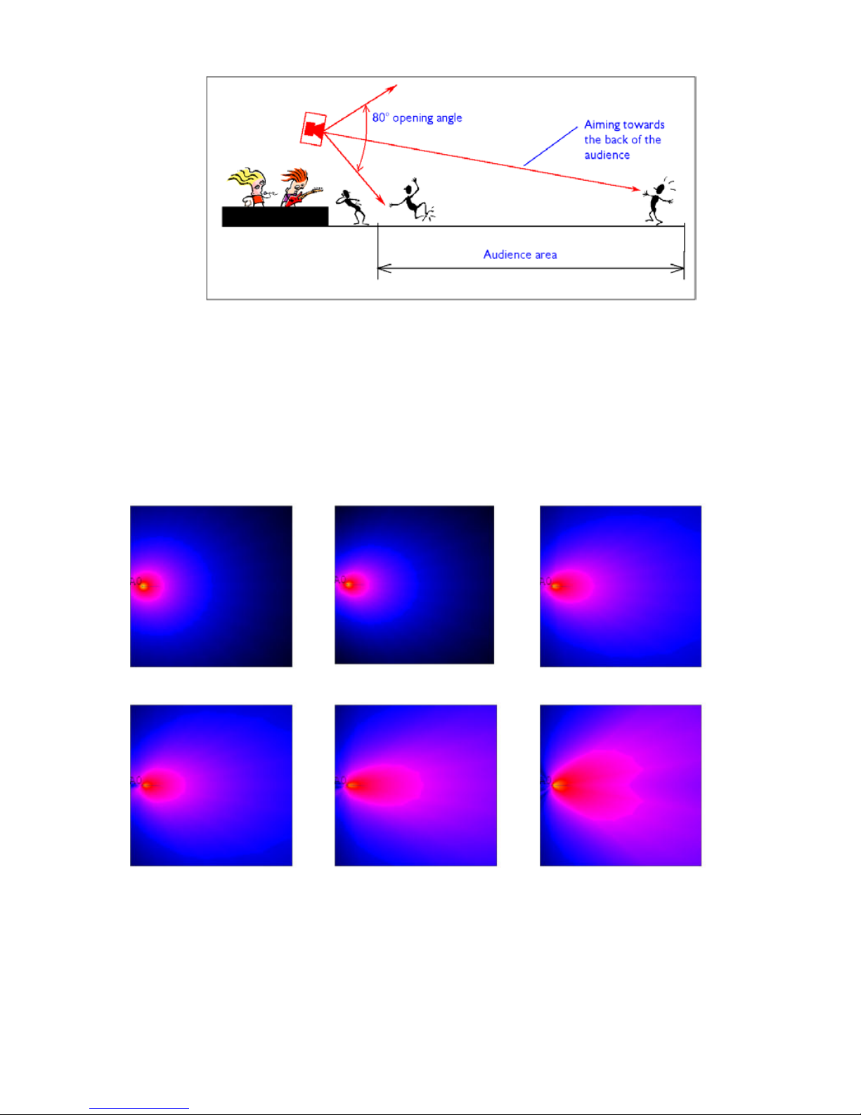
L-ACOUSTICS XT Manual V1.1 2/11/2003 27
Figure 10: General guidelines for aiming XT enclosures
4.3 ARRAYING XT ENCLOSURES
Figure 11 shows SPL mappings at octave band frequencies for a single XT enclosure (generated using
CATT-Acoustic modeling software), demonstrating the evenness of coverage and single point source
behavior that is obtained using coaxial technology.
Note: for color versions of figures 11, 12, 13 and 15 please see the XT manual PDF file that is available for
download from www.l-acoustics.com
125 Hz
250 Hz
500 Hz
1 kHz
2 kHz
4 kHz
Figure 11: SPL mappings at octave band frequencies for a single XT enclosure
Figure 12 shows SPL mappings at octave band frequencies for two XT enclosures with a spacing of 0.5
meters. Uneven coverage above 500 Hz demonstrates the comb filtering interference effects that
arise due to path length differences as a function of listener position.
Page 29
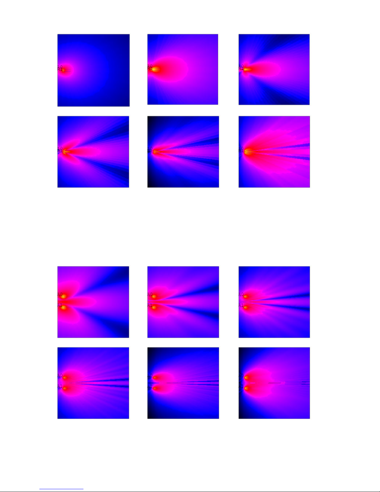
L-ACOUSTICS XT Manual V1.1 2/11/2003 28
125 Hz
250 Hz
500 Hz
1 kHz
2 kHz
4 kHz
Figure 12: SPL mappings at octave band frequencies for two XT enclosures with 0.5 metre spacing (arrayed
system corresponding to the “works” case shown in Figure 14)
Figure 13 shows SPL mappings for a distributed system of two XT enclosures with a spacing of 3
meters. Interference now occurs lower in frequency and will tend to be masked by room
reverberation. Compared with the closely spaced (arrayed) system of Fig. 12, there is now improved
intelligibility at higher frequencies. Essentially, the key to successful distributed system design is
reducing the effects of audible interference.
125 Hz
250 Hz
500 Hz
1 kHz
2 kHz
4 kHz
Figure 13: SPL mappings at octave band frequencies for two XT enclosures with 3 metre spacing (distributed
system corresponding to the “best” case shown in Figure 14)
Page 30
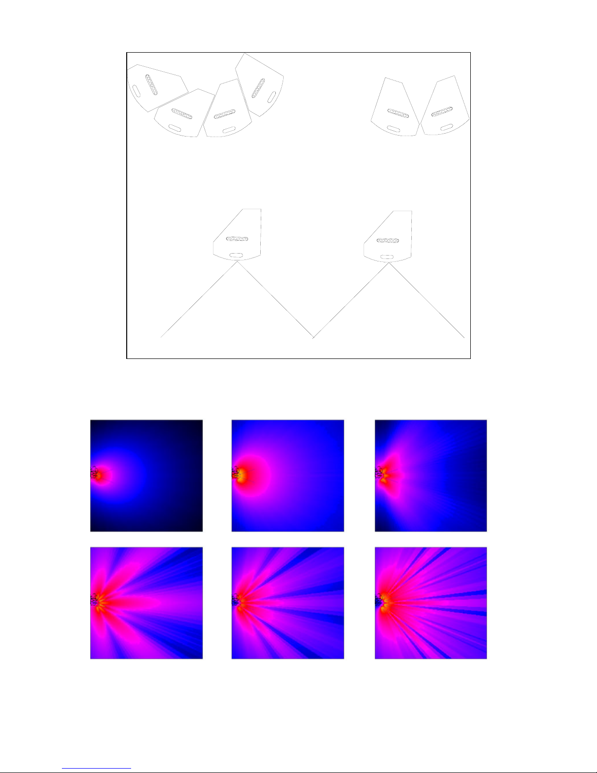
L-ACOUSTICS XT Manual V1.1 2/11/2003 29
AVOID
WORKS
BEST
Figure 14: General guidelines for arraying XT enclosures. The “avoid” case corresponds to the SPL mappings
shown in Figure 15, “works” corresponds to Figure 12 and “best” corresponds to Figure 13.
125 Hz
250 Hz
500 Hz
1 kHz
2 kHz
4 kHz
Figure 15: SPL mappings at octave band frequencies for four XT enclosures with 0.5 metre spacing (arrayed
system corresponding to the “avoid” case shown in Figure 14).
Page 31

L-ACOUSTICS XT Manual V1.1 2/11/2003 30
4.4 PREDICTING XT COVERAGE
Polar data files are available for modeling 112XT and 115XT coverage using industry-standard EASE
or CATT-Acoustic room acoustics modeling software packages (see Figures 11-13 for examples of
typical SPL mappings).
For more information on these modeling programs, please consult:
www.ada-acousticdesign.com
for EASE information
www.catt.se
for CATT.
112XT and 115XT polar data (EASE or CATT format) is available for download from:
www.l-acoustics.com
.
4.5 DISTRIBUTED SOUND REINFORCEMENT
As seen in Figure 13, distributed sound reinforcement using XT enclosures can provide even SPL
coverage and frequency response by reducing the effects of audible interference. For distributed
installation, the optimum spacing between enclosures will depend on the coverage angle of the
enclosure (90 degrees for 112XT, 80 degrees for 115XT) as well as the distance to listener.
4.5.1 OVERHEAD DISTRIBUTED SYSTEMS
Overhead distributed system design using coaxial loudspeakers is described in Davis and Davis, Sound
System Engineering, 2nd Edition, Focal Press, 1997. In this reference it is shown that an overhead
crisscross pattern distribution density with center-to-center overlap provides the most uniform
coverage (+/- 2 dB variation in SPL from between 250 – 5k Hz is possible). Formulae are provided for
various cases: center-to-center overlap, minimum overlap or no overlap in order to determine
physical layout parameters for the distributed loudspeaker grid. Interested readers are referred to
Chapter 13, “Distributed Sound Systems” in Sound System Engineering
for complete details.
4.5.2 DELAY SYSTEMS
XT enclosures are highly suited for delay system installation in order to cover large audience areas.
When installing delay systems, there are a few principles that should be followed:
1) Over-delaying up to 15 ms is acceptable due to the Haas effect. Greater than 15 ms is not
acceptable since the delayed sound will be perceived as an echo behind the main signal. Time
alignment of delays should be made using a measurement point on the axis of the reference source
and the delayed source. If the delay time setting is such that the two sources arrive at the same time
on-axis, the reference source will be slightly ahead of the delay source at any other location off-axis
and the Haas effect will allow for correct localization. For some applications (speech), it is advised to
under-delay in order to optimize off-axis intelligibility and clarity behind the delayed system (i.e.,
closer to the stage).
2) Spread different sources, with different delayed signals, instead of grouping them in a single
location. This allows for broader coverage by the delayed sources and produces more homogeneous
SPL over the delay-covered area.
3) Distributed delay positions should be along a circular arc of constant radius, centered at the stage.
4) The optimum spacing between delay loudspeakers will depend on the coverage angle of the
enclosure (90 degrees for 112XT, 80 degrees for 115XT) as well as the distance to first members of
the audience. Center-to-center overlap will provide the most uniform coverage (see also 4.5.1).
Time domain-based measurement equipment is essential for setting delay times (for example, MLSSA,
WINMLS, TEF, SMAART or SPECTRAFOO). Alternatively, Bushnell Yardage Pro rangefinder
binoculars can provide a good starting point by simply measuring the distance from the delay location
to the main system, i.e., the geometric path difference.
Page 32

L-ACOUSTICS XT Manual V1.1 2/11/2003 31
4.5.3 COMPLEMENTARY FILL
For large-scale sound reinforcement (typically when V-DOSC, dV-DOSC or ARCS are used as the
main FOH system), XT enclosures can be used for distributed front fill (ground stacked), flown center
cluster downfill, stereo in-fill, offstage fill or as distributed delays. The number of potential uses for
112XT or 115XT enclosures for fill applications is only limited by your imagination.
In all cases, proper time alignment of fill systems with respect to the main L/R FOH system is essential
for obtaining optimum results. Similarly, pre-delay to time align the overall sound reinforcement
system (main L/R FOH plus fill systems) with the energy generated on stage is also an important
consideration for the first 10 rows of the audience. WINMLS, SMAART or SPECTRAFOO are costeffective measurement tools for performing time alignment that are recommended.
FLOWN CENTER CLUSTER
Due to their compact size, point source behavior and generous coverage, XT enclosures are highly
suitable for center cluster applications. Typically this will be necessary when the stage opening is wide
and the left/right FOH system separation is more than 20 meters. Apart from coverage issues, image
localization is an important consideration (particularly for theatrical installations) and careful time
alignment plus attenuation can significantly improve subjective localization for the audience to the
onstage performers. In some cases, two XT enclosures can be arrayed vertically as a center cluster
and considered as separate floor and balcony systems with different signal processing (time delay,
level, equalization) applied to the individual XT enclosures in order to optimize image localization for
the two separate audience areas. Trim height and tilt of an XT center cluster fill system will depend
on the distance to the first rows of the audience and on the height of the proscenium opening.
DISTRIBUTED FRONT FILL
As an alternative (or complement) to a flown center cluster, XT enclosures can be stacked on top of a
central line array of subwoofers (or any other object of suitable height) provided that the height of the
HF section is appropriate for audience coverage. Typically, a stacked height of at least 1-2 meters is
recommended in order to reduce audience shadowing effects and whether the audience is seated or
standing should also be considered. In addition to these issues, sightlines and clearance under the stage
lip are also important considerations for a distributed front fill system and when space is at a premium,
the MTD108a (or dV-DOSC) can be considered as alternatives.
As for overhead distributed or delay systems, the optimum spacing between XT enclosures will
depend on the coverage angle of the enclosure (90 deg for 112XT, 80 deg for 115XT) and the
distance to the first members of the audience. Center-to-center overlap will provide the most uniform
coverage and separate time alignment delay taps for front fill enclosures can further assist in improving
image localization.
STEREO INFILL
Stacked stereo infill systems using XT enclosures either located onstage or stacked on top of L/R
ground stacked subwoofer arrays can also be effective for front fill purposes. It is always a good idea
to keep XT enclosures physically as close as possible to the subwoofers in order to improve sonic
integration between the fill system and the subwoofers plus to reduce low frequency proximity effects
for the audience located close to the subwoofers (i.e., it’s good to give the audience some high end to
help offset all that sub energy!). For smaller set designs, it can also be an option to place stereo frontfill XT enclosures close to the onstage side-fill monitoring system.
As for distributed front fill applications, the height of the HF section should be optimized to suit the
audience seating area in order to reduce shadowing effects. Special attention should be paid to the
first few rows and a stacked height of at least 1-2 meters is recommended. If possible, use distanceattenuation loss to your advantage and move XT enclosures as far upstage as possible in order to
reduce the increase in SPL over the first few rows relative to the audience further back in the
coverage region.
Page 33

L-ACOUSTICS XT Manual V1.1 2/11/2003 32
OFFSTAGE FILL
When the horizontal coverage of the main left/right FOH arrays is not sufficient to cover the entire
audience area, XT enclosures can also be used for offstage fill. Typically, throw distance requirements
are shorter and vertical coverage angles are greater, making XT a possible solution for this application.
Some Final Notes Concerning Fill Applications
Digital processor presets for 112XT and 115XT loudspeaker enclosures have been specifically engineered to
be sonically compatible with all other L-ACOUSTICS models.
FILL presets (nominally flat) are recommended for all proximity fill applications where the audience is
located close to fill loudspeakers – for example, front fill or stereo infill configurations.
Time alignment of complementary fill systems with the main left/right FOH arrays is necessary in order to
achieve optimum results. Placing your measurement microphone in a representative location where the fill
and main system coverage overlaps generally provides a good reference point for time alignment. WINMLS,
SMAART or SPECTRAFOO are cost-effective measurement tools that are recommended for this purpose.
4.6 FRONT-OF-HOUSE (FOH) APPLICATIONS
When 112XT or 115XT enclosures are used standalone (without subwoofers) for FOH applications,
there are two different types of 2-way preset available: 1) FRONT presets
have 3 dB of low and high
frequency shelving equalization in order to provide a frequency response contour that is suitable for
music applications; 2) FILL presets
have nominally flat response for use in speech reinforcement and
classical music applications or for when XT enclosures are used as a close proximity fill enclosure.
For 3-way operation of 112XT or 115XT loudspeaker enclosures with SB115, SB118, SB218 or dVSUB subwoofers there are two different types of preset available: 1) 3W presets
optimize the power
bandwidth for the XT and its companion subwoofer due to the use of complimentary 100 Hz
crossover filtering and are recommended for all closely-coupled applications (for example, stacked
configurations); 2) 3WX presets
can be employed when XT enclosures and subwoofers are physically
separated (for example, flown XT enclosures and ground stacked subwoofers).
For all FOH applications, please refer to Sections 4.2, 4.3, 4.4 concerning XT aiming, arraying and
coverage prediction. For additional information on using XT enclosures with subwoofers, please refer
to Section 4.8.
4.7 STAGE MONITORING
Given the power of digital signal processing and due to their compact, wedge-shaped format and axisymmetrical directivity, XT enclosures provide an extremely high performance, “plug and play” stage
monitoring solution.
FLOOR MONITORING
For floor monitoring applications, the coaxial component configuration employed in the 112XT and
115XT provides a high degree of image and coverage stability. The benefits of axi-symmetric
directivity are even more apparent since the performer is in close physical proximity to enclosure and
experiences a generous, homogeneous coverage pattern without the subjective impression (and
potential feedback problems) of listening to a separate horn / woofer combination.
MONITOR presets include additional low frequency equalization to account for half-space loading
conditions and are intended for either floor monitoring applications or fixed installations where the
XT is wall- or ceiling-mounted. In general, under half-space loading conditions, there is a 6 dB increase
around 100 Hz (due to floor coupling), followed by a broad cancellation that occurs between 200 –
Page 34
L-ACOUSTICS XT Manual V1.1 2/11/2003 33
600 Hz (due to floor reflections). MONITOR presets compensate for these two half-space loading
effects and provide a frequency response curve that is nominally flat.
Subjectively, low frequency half-space loading compensation provides a high degree of “warmth and
body” to vocals, while the flat high frequency response that has been engineered for the MONITOR
preset provides excellent fidelity and feedback resistance. Since the overall MONITOR response
curve is nominally flat, simple adjustments to the relative output gains between high and low channels
allow the monitor engineer to quickly adjust the overall response contour to obtain more vocal
presence (as desired). Power response is very even and stable due to the axi-symmetric directivity of
the coaxial component configuration and this results in improved coverage and feedback resistance.
When using XT enclosures in pairs for floor monitoring, the same principles apply as for overhead or
distributed front fill systems, i.e., the optimum spacing between floor monitors will depend on the
coverage angle of the enclosure (90 degrees for 112XT, 80 degrees for 115XT) and the throw
distance to the performing artist (which is determined by the floor monitor angle with respect to
vertical and the artist’s height). Center-to-center overlap will provide the most uniform coverage and
as a guideline, nominal monitor distance plus monitor separation is tabulated below in Table 11.
Table 11: Nominal floor monitor distance (to performer) and monitor separation versus performer height
112XT (45 deg angle wrt vertical, 90 deg coverage)
PERFORMER HEIGHT Performer <-> Monitor Monitor <-> Monitor
(cm) (ft / in) (cm) (ft / in) (cm) (ft / in)
160 5 ft 3 in 160 5 ft 3 in 160 5 ft 3 in
165 5 ft 5 in 165 5 ft 5 in 165 5 ft 5 in
170 5 ft 7 in 170 5 ft 7 in 170 5 ft 7 in
175 5 ft 9 in 175 5 ft 9 in 175 5 ft 9 in
180 5 ft 11 in 180 5 ft 11 in 180 5 ft 11 in
185 6 ft 1 in 185 6 ft 1 in 185 6 ft 1 in
190 6 ft 3 in 190 6 ft 3 in 190 6 ft 3 in
115XT (41 deg angle wrt vertical, 80 deg coverage)
PERFORMER HEIGHT Performer <-> Monitor Monitor <-> Monitor
(cm) (ft / in) (cm) (ft / in) (cm) (ft / in)
160 5 ft 3 in 139 4 ft 7 in 117 3 ft 10 in
165 5 ft 5 in 143 4 ft 8 in 120 3 ft 11 in
170 5 ft 7 in 148 4 ft 10 in 124 4 ft 1 in
175 5 ft 9 in 152 4 ft 12 in 128 4 ft 2 in
180 5 ft 11 in 156 5 ft 2 in 131 4 ft 4 in
185 6 ft 1 in 161 5 ft 3 in 135 4 ft 5 in
190 6 ft 3 in 165 5 ft 5 in 139 4 ft 7 in
Apart from separation and distance to the performer, the last issue to consider when using 112XT or
115XT as floor monitors in paired configurations is whether to angle them in towards the performer.
Although it looks more “rock and roll” and gives the performer the impression of having more SPL, it
is generally not advised to angle wedges in but to use them with the front faces parallel to each other.
Essentially, angling in wedges no longer provides optimum center-to-center overlap and results in too
much overlap. Due to this excessive overlap, there will be a cancellation loss of up to 8 dB in the high
end (above 6 kHz, approximately) that will need to be compensated for via output gain adjustment
and/or equalization. Ultimately, it all comes down to artist preference and what you’re shooting for in
a monitor mix but if you want optimum coverage and nominally flat, follow the spacing/distance
recommendations above and don’t angle the wedges in.
Page 35
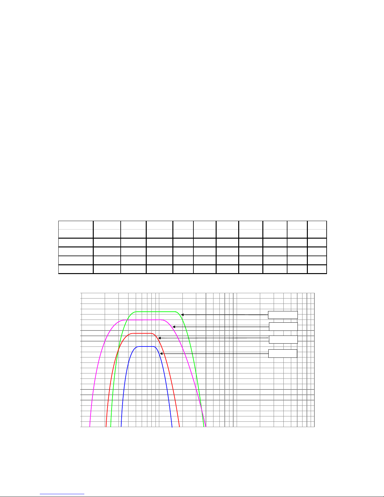
L-ACOUSTICS XT Manual V1.1 2/11/2003 34
SIDE FILL OR DRUM FILL MONITORING
When used in conjunction with SB115, SB118, SB218 or dV-SUB subwoofers, 112XT or 115XT
enclosures provide an excellent solution for side fill or drum fill monitoring. Single or two enclosure
stacked configurations are the most common set-up for these applications and the XT can also be
used without subwoofers depending on the amount of LF extension expected by the monitor
engineer or performing artist.
When stacked on top of vertically-oriented SB118 or SB218 subwoofers for side fill applications, XT
enclosures will physically be at a convenient height that is close to the performer’s ear level. Normally
for drum fill, subwoofers will be oriented horizontally in order to maintain a low profile.
Since the XT and its companion subwoofer are physically coupled for side fill or drum monitoring
applications, 3W presets are recommended since complimentary 100 Hz crossover filtering optimizes
the power bandwidth for the subwoofer and the 112XT or 115XT low section (please see Section 4.8
for further details).
4.8 USING XT WITH SUBWOOFERS
For most music applications, 112XT or 115XT enclosures should be used with SB115, SB118, SB218
or dV-SUB subwoofers. Issues involved in effectively using XT with subwoofers are discussed below
and as a reference, L-ACOUSTICS subwoofer specifications are summarized in Table 12 and Fig 14.
Table 12: L-ACOUSTICS Subwoofer Specification Summary
L-ACOUSTICS Fre q Re sp Usa ble LF Se nsitivity RMS POW ER POWER MAX SPL MAX SPL REC'D LOAD
SUB MODEL (+/- 3 dB) (-10 dB) (1W / 1m) Voltage (cont) (peak) (cont) (peak) AMP (ohms)
SB115 45 - 100 Hz 40 Hz 94 45
250 W 1000 W
120 dB 126 dB 500 W 8
SB118 35 - 100 Hz 32 Hz 97 70 600 W 2400 W 125 dB 131 dB 1200 W 8
SB218 28 - 140 Hz 25 Hz 100.5 68 1100 W 4400 W 130 dB 136 dB 2200 W 4
dV-SUB 40 - 200 Hz 35 Hz 104.5 57 1200 W 4800 W 133 dB 139 dB 2400 W 2.7
90.0
92.0
94.0
96.0
98.0
100.0
102.0
104.0
106.0
108.0
110.0
112.0
114.0
116.0
118.0
120.0
122.0
124.0
126.0
128.0
130.0
132.0
134.0
136.0
138.0
140.0
10 100 1000 10000
frequency (Hz)
dB SPL Continuous re: one source
SB118
SB115
-
SB218
Figure 16: L-ACOUSTICS Subwoofer Continuous Unweighted SPL Comparison
Page 36

L-ACOUSTICS XT Manual V1.1 2/11/2003 35
All 3-way XT presets have been optimized to provide a 6 dB low frequency contour when
subwoofers are used with 112XT or 115XT enclosures in a 1:1 XT:subwoofer ratio. In order to
compensate for sensitivity differences between subwoofer models, relative sub, low and high output
channel gains have been adjusted for individual presets so that the same 6 dB low frequency contour is
obtained, regardless of the subwoofer model in use.
4.8.1 Combining XT With Subwoofers
Two cases can be considered: ground stacked systems where XT and subwoofer enclosures are
closely coupled physically or separate flown XT loudspeakers with ground stacked subwoofers. For
both cases, processing will depend on the intended purpose of the subwoofers, i.e., in some
applications, subwoofers are used as an effect and are not driven with the same signal as the main XT
system (separate auxiliary send from the console) while in other cases, the subwoofers are used as a
low frequency extension of the array and are driven with the same signal in 3-way mode.
In general:
3W Presets
have a 100 Hz 24 dB/octave Linkwitz-Riley (LR24) low pass filter for the subwoofers with
a complimentary 100 Hz LR24 high pass filter for the 112XT or 115XT low section. Complimentary
100 Hz crossover filtering optimizes the power bandwidth for the subwoofer and the 112XT or
115XT low section. 3W presets are recommended for all stacked XT/subwoofer applications where
the enclosures are closely coupled physically.
3WX presets
have an 80 Hz LR24 low pass filter for the subwoofers and an overlapping LR24 high
pass filter for the XT low section (45 Hz HPF for 112XT, 40 Hz HPF for 115XT). Due to the overlap
in the operating bandwidths of the sub and low sections, subwoofer polarity may have to be inverted
due to the phase shift of overlapping crossover filters (depending on the selected preset and how the
subwoofers are driven, i.e., via AUX send or with the same signal as sent to the XT system)
4.8.2 Ground Stacked Systems
For ground stacked systems, XT and subwoofer enclosures are physically close to each other and time
alignment is simplified throughout the audience area since there are no arrival time (path length)
differences between the flown XT system versus ground stacked subwoofers. Typically, 3W presets
are used for ground stacked configurations in order to optimize power bandwidth for the subwoofer
and XT low section and the overall system is driven in either 3-way mode or with separate AUX drive
(although 3WX presets can also be used).
4.8.3 Separate Flown XT Array with Ground Stacked Subwoofers
For a separate flown XT array with ground stacked subwoofers, time alignment of subwoofers is
required due to the geometric path difference between the two systems. This is illustrated in Figure
17, where the distance from the measurement microphone position to the subwoofers is d
SUB
while
the distance to the flown XT system: d
FLOWN
= d
SUB
+ PATH DIFFERENCE. Delaying the subwoofers
by the geometric path difference will time align the subwoofers at the reference position.
Note: Selection of the reference position for time alignment is always a compromise since the geometric
path difference will vary with position.
Page 37
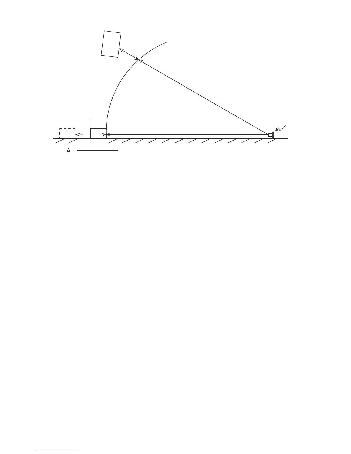
L-ACOUSTICS XT Manual V1.1 2/11/2003 36
STAGE
PATH
DIFFERENCE
MEASUREMENT
MICROPHONE
FLOOR
TIME DELAY
(SB218)
(FLOWN
SYSTEM)
d
sub (m)
d
FLOWN=
d+
SUB
PATH DIFFERENCE
d
s
u
b
(m
)
(SB218)
PATH DIFFRENCE (meters)
343 (meters/second)
T
=
Figure 17: Illustration of subwoofer time alignment
In most cases, 3W presets are used for flown XT and ground stacked subwoofer configurations in (3way mode or with separate AUX drive for the subwoofers) since the subwoofers can be used with
positive polarity and this helps to simplify installation and system tuning.
If more low frequency energy is desired from the flown XT system, 3WX presets can be used and
subwoofer polarity will depend on how subwoofers are processed, i.e., whether they are driven with
the same signal as the XT enclosure or driven via discrete AUX send. Following time alignment,
subwoofer polarity is a parameter to experiment with in order to obtain the best results.
Page 38
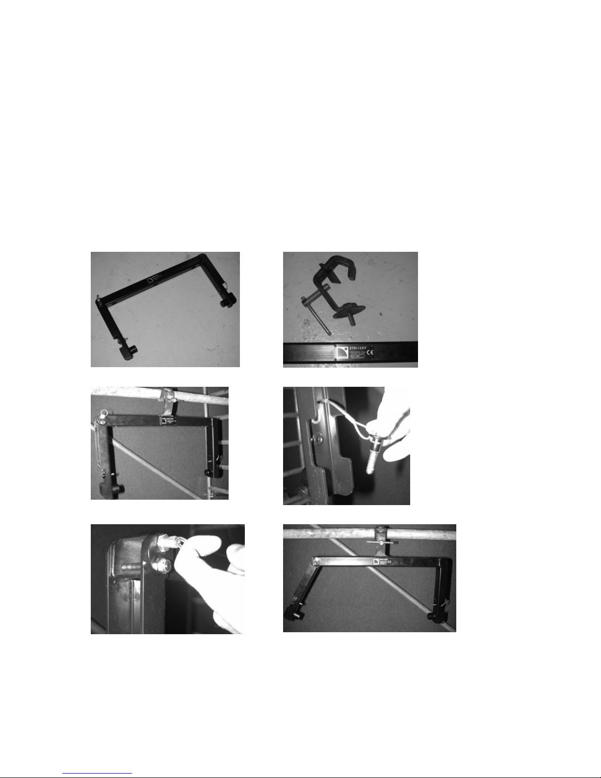
L-ACOUSTICS XT Manual V1.1 2/11/2003 37
5. INSTALLATION PROCEDURES
5.1 ETR112XT, ETR115XT U-BRACKET ATTACHMENT
ETR112XT and ETR115XT are optional accessory U-Brackets for ceiling, wall or scaffold mounting of
the 112XT or 115XT, respectively, in either horizontal or vertical orientations. Three mount holes
are available on the center section of the ETR112XT and ETR115XT for bracket mounting. Pole
mount adapter plates on 112XT and 115XT enclosures allow for 10 degree angular resolution.
Note: When using ETR112XT or ETR115XT in the vertical orientation, always install with the fixed arm on
the bottom and the pivoting arm on top.
(1) ETR112XT U-bracket
(2) Scaffold clamp (not supplied)
(3) Premounted ETR112XT
(4) Remove locking pins on both U-bracket arms
(5) Remove locking pin for pivoting arm
(6) ETR112XT - ready to mount the 112XT
Page 39
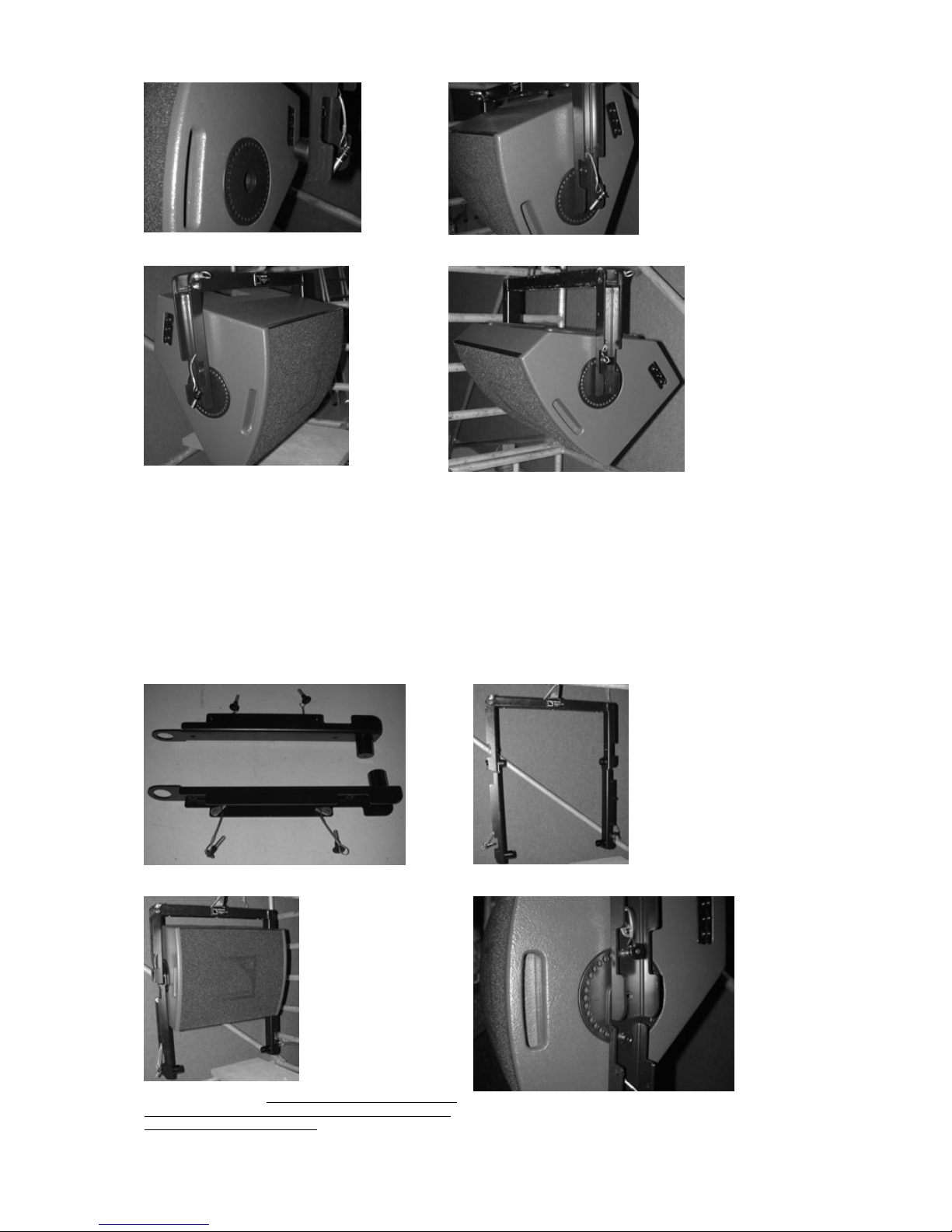
L-ACOUSTICS XT Manual V1.1 2/11/2003 38
(7) 112XT pole mount sockets mate with U-bracket studs
(8) Mount the 112XT in the fixed arm side first
(9) Rotate the pivoting arm into position – the locking pin
automatically secures the U-bracket
(10) Rotate the loudspeaker into position to select the desired angle. Secure
using the locking pins on both fixed and pivoting arms
Figure 18: ETR112XT, ETR115XT U-bracket installation procedure
5.2 CPL112XT, CPL115XT COUPLING ADAPTER BAR ATTACHMENT
The CPL112XT or CPL115XT coupling adapter bars are optional accessories that can be used in
conjunction with ETR112XT or ETR115XT U-brackets to array two 112XT or 115XT enclosures
vertically (with independent tilt adjustment for both enclosures).
(1) CPL112XT coupling adapter bar kit
(2) CPL112XT pre-installed with ETR112XT
(3) Install the top 112XT. Ensure that the ETR112XT rotating arm
is properly secured by verifying that the spring-loaded locking pin
at the pivot point is correctly seated.
(4) Select angle and secure top locking pins on both sides for the
upper 112XT (do not attach middle locking pins for the CPL112XT)
Page 40
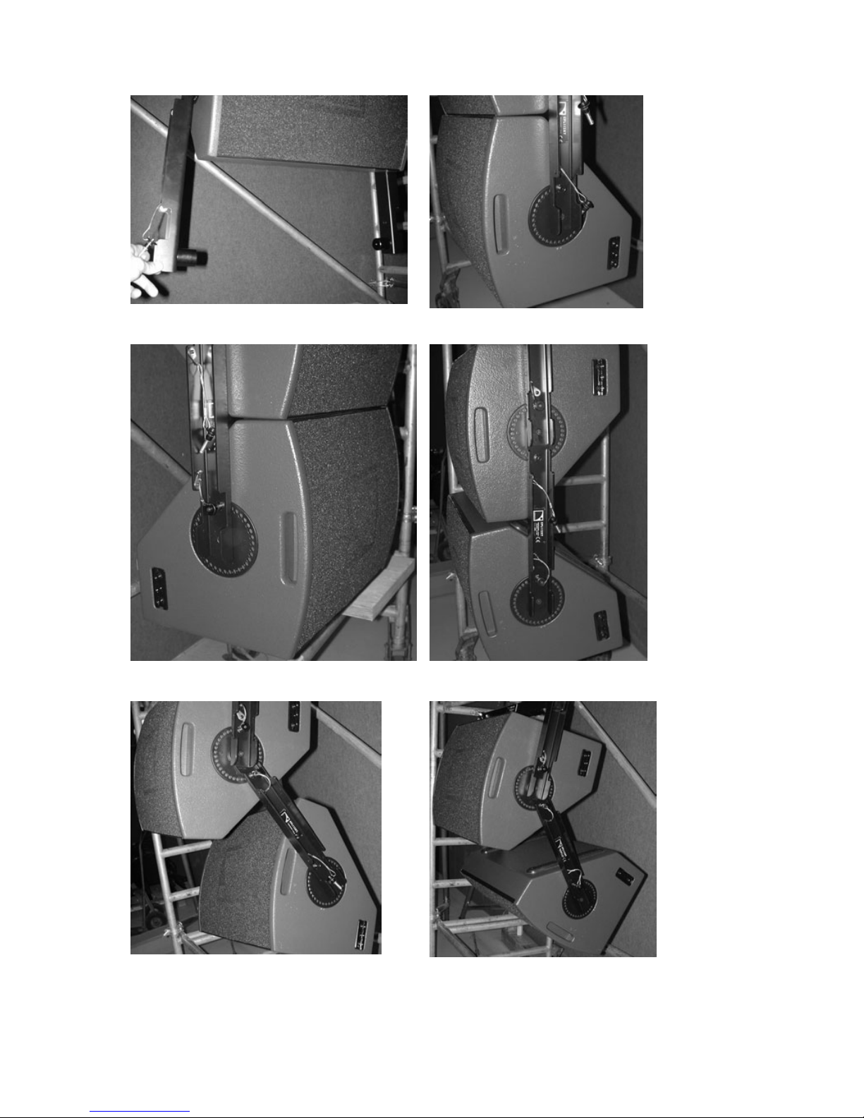
L-ACOUSTICS XT Manual V1.1 2/11/2003 39
(5) With middle locking pins unattached, the CPL112XT is free to
rotate, facilitating installation of the lower 112XT
(6) Lower 112XT installed
(7) Attach lower locking pins on both sides of the lower 112XT to
facilitate angling of the CPL112XT
(8) Attach lower locking pins on both sides of the lower 112XT to
facilitate angling of the CPL112XT
(9) Release lower locking pins to perform final angling of the lower
112XT once CPL112XT angle has been set and middle locking
pins installed
(10) The final installed system. Side flytrack sections and PION2
accessories can be used for installation of safety security steels
Figure 19: CPL112XT, CPL115XT coupling adapter installation procedure
Page 41
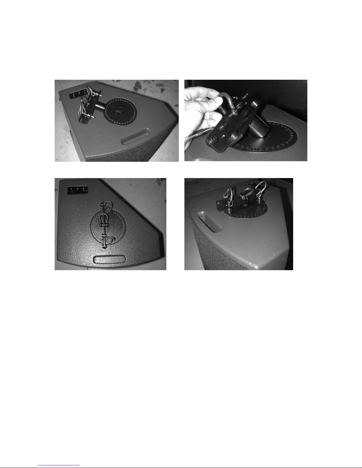
L-ACOUSTICS XT Manual V1.1 2/11/2003 40
5.3 XTLIFTBAR ATTACHMENT
The optional XTLIFTBAR accessory allows for single point rigging of 112XT or 115XT loudspeaker
enclosures with 5 pick points available for tilt adjustment. Pick point holes (from front to back)
provide tilt angles of +14, +7, 0, -7 or -14 degrees for either 112XT or 115XT.
(1) XTLIFTBAR and the 112XT enclosure
(2) The XTLIFTBAR mounting stud mates with 112XT or 115XT
pole mount sockets (top or bottom)
(3) When installing XTLIFTBAR, ensure that the main section is
aligned with the center of the enclosure in order to properly balance
the center of gravity. The flytrack section and PION2 (optional
accessory) can be used to install a safety steel.
(4) Two locking pins are used to secure the XTLIFTBAR. Changing
the shackle location provides tilt angles of +14, +7, 0, -7, -14
degrees (front to back).
Figure 20: XTLIFTBAR installation procedure
5.4 SAFETY RULES
Always ensure that the ETR112XT or ETR115XT rotating arm is securely fastened by verifying that
the spring-loaded locking pin at the pivot point is correctly seated before adjusting the tilt angle of the
112XT or 115XT.
When using ETR112XT or ETR115XT in the vertical orientation, always install the U-bracket with the
fixed arm on the bottom and the pivoting arm on top.
Maximum two 112XT enclosures can be rigged using ETR112XT in conjunction with CPL112XT.
Maximum two 115XT enclosures can be rigged using ETR115XT in conjunction with CPL115XT.
Maximum one 112XT or 115XT can be rigged per XT liftbar.
L-ACOUSTICS recommends the use of safety steels at all times. The recessed, side-mounted fly track
sections can be used with the PION2 double stud fitting to ring accessory for safety attachment to
112XT and 115XT enclosures.
Page 42

L-ACOUSTICS XT Manual V1.1 11-02-03 41
6. XT SYSTEM OPERATION
Connect program signal lines (L/R outputs from a mixing console, for example) to the A and B channel
inputs of the digital signal processor (XTA DP224, DP226 or BSS 366).
With reference to the output channel assignments given in the Preset Description sheets (see also
Figures 5, 6 or 7), connect the outputs of the DSP unit to the corresponding amplifier inputs (directly
or via your signal distribution / return snake multicore system).
For 6 channel units (XTA DP226 and BSS 336 or 366) outputs 1, 2, 3 correspond to Sub, XT low, XT high
for input A while output channels 4, 5, 6 correspond to Sub, XT low, XT high for input B.
Power up the DSP unit and select the appropriate preset for 2-way operation (FRONT, FILL or
MONITOR) or 3-way operation (3W or 3WX for 112XT or 115XT plus SB115, SB118, SB218, dVSUB subwoofers).
Perform the following steps as a system check:
1) turn down the level of all amplifier channels before turning the amplifiers on
2) un-mute the HIGH crossover channel
3) send a pink noise signal to the crossover
4) turn up the level of each HIGH amplifier channel individually and check that this provides
the expected frequency band in the expected loudspeaker component. Test each HIGH
amplifier channel individually until all HIGH amplifier channels have been tested.
5) mute the HIGH crossover channel
6) repeat steps 2-5 for LOW and SUB channels
7) turn off the pink noise
Set all amplifier output levels to 0 dB gain
Un-mute all crossover output channels and the system is ready for use.
Remember the old saying: “amps on last, amps off first” in order to avoid component damage due to power
on/off transients.
6.1 RECOMMENDED MAINTENANCE PROCEDURES
a) HF diaphragm replacement
To access the HF compression driver diaphragm, the front grille of the XT enclosure should be
removed and the entire 12” or 15” coaxial assembly de-mounted.
To remove the front grille, lift the edges of the acoustic foam and remove the screws. Screws can be
found where the edges of the foam are not glued onto the grille (there is no need to completely
remove the acoustic foam in order to remove the loudspeaker grille).
Once the coaxial assembly has been de-mounted, unscrew the back cover of the rear-mounted
compression driver assembly to obtain access to the compression driver diaphragm.
Remove the damaged diaphragm and before installing the replacement diaphragm ensure that the
voice coil gap is free from any metallic particles, dirt or other debris by using 2-sided tape and
acetone, if necessary, to thoroughly clean out the gap.
After installing the replacement diaphragm, apply a low level, low frequency sine wave sweep (for
example: 4 volts from 100 Hz - 1 kHz) to ensure that the diaphragm is properly centered in the gap
before reinstalling the compression driver back cover. Make sure all compression driver diaphragm
and back cover mount screws are securely fastened (loctite is optional but recommended).
Page 43
L-ACOUSTICS XT Manual V1.1 11-02-03 42
As a final check apply a high level sine sweep over the HF compression driver’s operating bandwidth
(for example: 13 volts from 1 kHz to 18 kHz).
Re-mount the entire XT coaxial assembly in its enclosure and perform a system polarity check.
Following service, the damaged compression driver diaphragm should be returned to your distributor
or directly to L-ACOUSTICS for warranty examination.
b) LF Service
The 12” or 15'' loudspeaker components of the coaxial assemblies used in the 112XT and 115XT are
not field-serviceable. For field service, the entire coaxial assembly should be removed and replaced.
To remove the front grille, lift the edges of the acoustic foam and remove the screws. Screws can be
found where the edges of the foam are not glued onto the grille - there is no need to completely
remove the acoustic foam in order to remove the loudspeaker grille.
The damaged loudspeaker should be returned to your distributor or directly to L-ACOUSTICS for
warranty examination and reconing.
c) Polarity Check
Whenever a HF diaphragm or loudspeaker component is replaced, wiring polarity should be checked
with a polarity checking device. Both LF and HF components should operate with positive polarity.
d) Periodic Check
The frequency response of the enclosure should be checked periodically to check for any deviations
due to wear, shock or other damage. This should be done on an annual basis for systems not
subjected to demanding use. For systems being used on a daily basis for sub hire or touring,
enclosures should be checked every month (or even more frequently).
A frequency response check can be performed with a high resolution RTA (real time analyzer), or
preferably using WINMLS, SMAART, SPECTRAFOO, TEF or MLSSA measurement systems. Refer to
the on-axis amplitude/frequency response to determine if your XT enclosure is within specification. In
addition, a response sweep using a sine wave generator is useful for checking for coil rubs, buzzes, air
leaks or other undesirable mechanical vibrations as part of the periodic quality control procedure.
The mechanical attachment of both low frequency and high frequency loudspeakers should be
checked periodically since mount screws can become loose after being submitted to intense, long
duration mechanical vibrations. Similarly, it is a good idea to periodically check that the high frequency
diagram and rear cover for the compression driver are solidly attached. The quality of the contacts
and locking action of the SPEAKON connector should also be checked periodically.
6.2 SPARE PARTS
112XT 115 XT
HP BC121 12" coaxial speaker 8 Ohms HP BC151 15" coaxial speaker 8 Ohms
HS BC31 Diaphragm for 1,4" driver HS BC32 Diaphragm for 1,4" driver
HS BC121 12" recone kit HS BC151 15" recone kit
HR BC121 12" recone kit inc. labour HR BC151 15" recone kit inc. labour
CM 112XT Front foam CM 115XT Front foam
MC 112XTGRL Front grill MC 115XTGRL Front grill
CD COLNEO Neoprene glue 500ML CD COLNEO Neoprene glue 500ML
Page 44

L-ACOUSTICS XT Manual V1.1 11-02-03 43
7. SPECIFICATIONS
7.1 112XT ELEMENT SPECIFICATIONS
Frequency Response
Frequency response: 65 – 18k Hz (± 3 dB) (FRONT preset)
Usable bandwidth: 55 – 18k Hz (-10 dB)
Sensitivity
LF (2.83 Vrms at 1 m) 98.5 dB SPL (65 – 1k Hz)
HF (2.83 Vrms at 1 m) 106 dB SPL (1 – 18 kHz)
Power Rating Amplification Impedance
(Long Term) (recommended) (nominal)
LF 48 Vrms 290 Wrms 1160 Wpeak 580 W 8 ohms
HF 33 Vrms 135 Wrms 540 Wpeak 540 W 8 ohms
Nominal Directivity (-6 dB)
Axi-symmetrical 90° (± 20°)
System Output SPL
One enclosure 122 dB (cont) 128 dB (peak) FRONT preset
124 dB (cont) 130 dB (peak) FILL preset
125 dB (cont) 131 dB (peak) 3W preset
FRONT preset provides 3 dB low and high frequency contours under freefield conditions
FILL preset provides nominally flat response under freefield conditions
3W preset applies a 100 Hz high pass filter.
Components
LF 1 x 12” weather resistant loudspeaker (3” voice coil)
HF 1 x 1.4” exit compression driver (titanium diaphragm, 3” voice coil, coaxial assembly)
Enclosure
Height 540 mm 21.3 in
Front Width 410 mm 16.1 in
Rear Width 165 mm 6.5 in
Depth 375 mm 14.8 in
Trap Angle 45 degrees with respect to vertical
Net Weight 27 kg 59.5 lbs
Shipping Weight 30 kg 66.1 lbs
Shipping Dimensions 615 x 470 x 465 mm
24.2 x 18.5 x 18.3 in
Connectors 2x 4-pin Neutrik speakon
Material 18 mm, 30 mm Baltic birch plywood
(sealed, screwed and rabbeted angles)
Finish Maroon-gray™
Grill Black epoxy perforated steel with acoustically transparent foam
Rigging Integrated flying hardware, handles and pole mount socket
Page 45
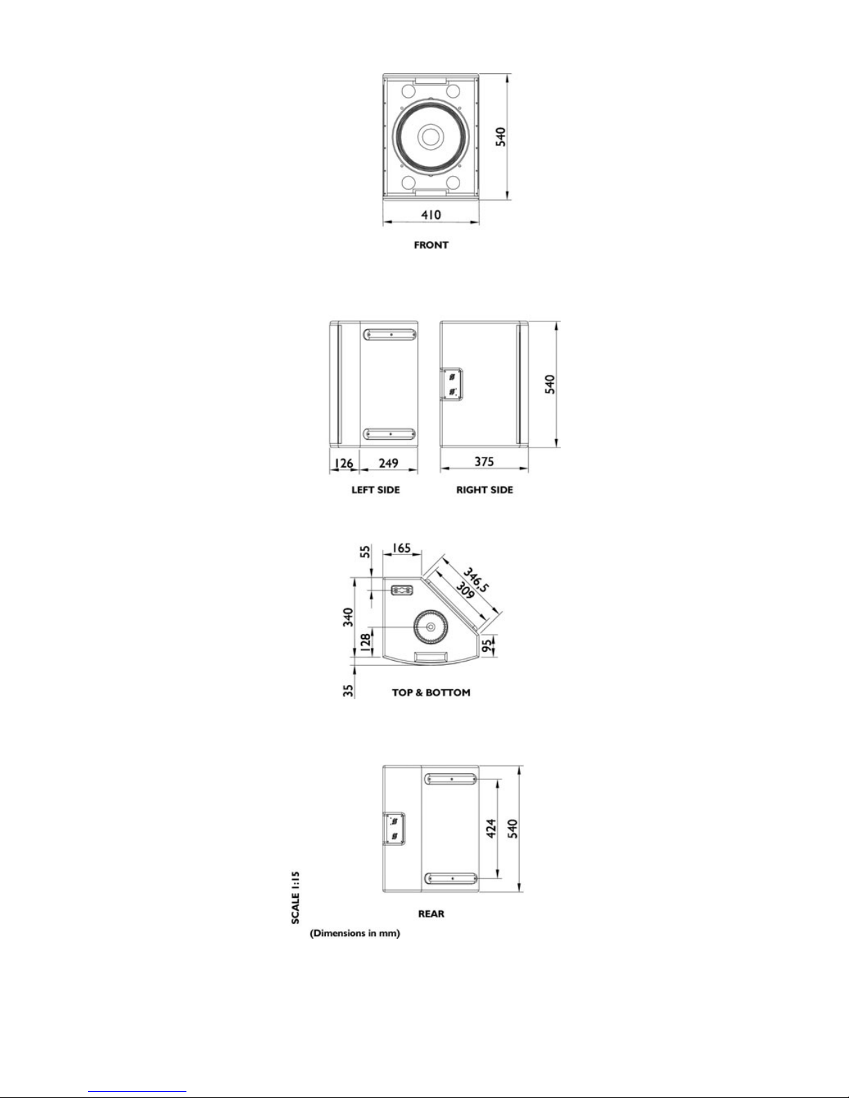
L-ACOUSTICS XT Manual V1.1 11-02-03 44
Figure 21: 112XT Line Drawing
Page 46
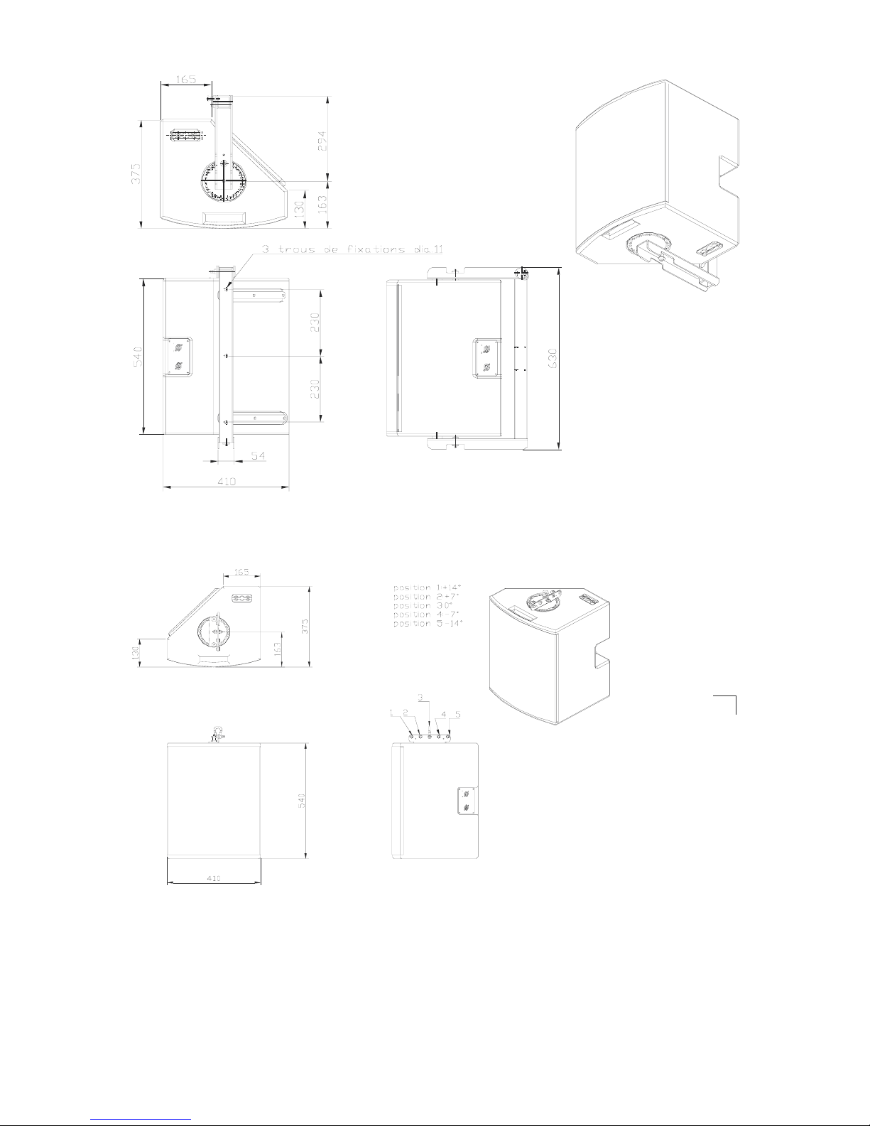
L-ACOUSTICS XT Manual V1.1 11-02-03 45
Figure 22: 112XT + ETR112XT Line Drawing
Figure 23: 112XT + XTLIFTBAR Line Drawing
Page 47
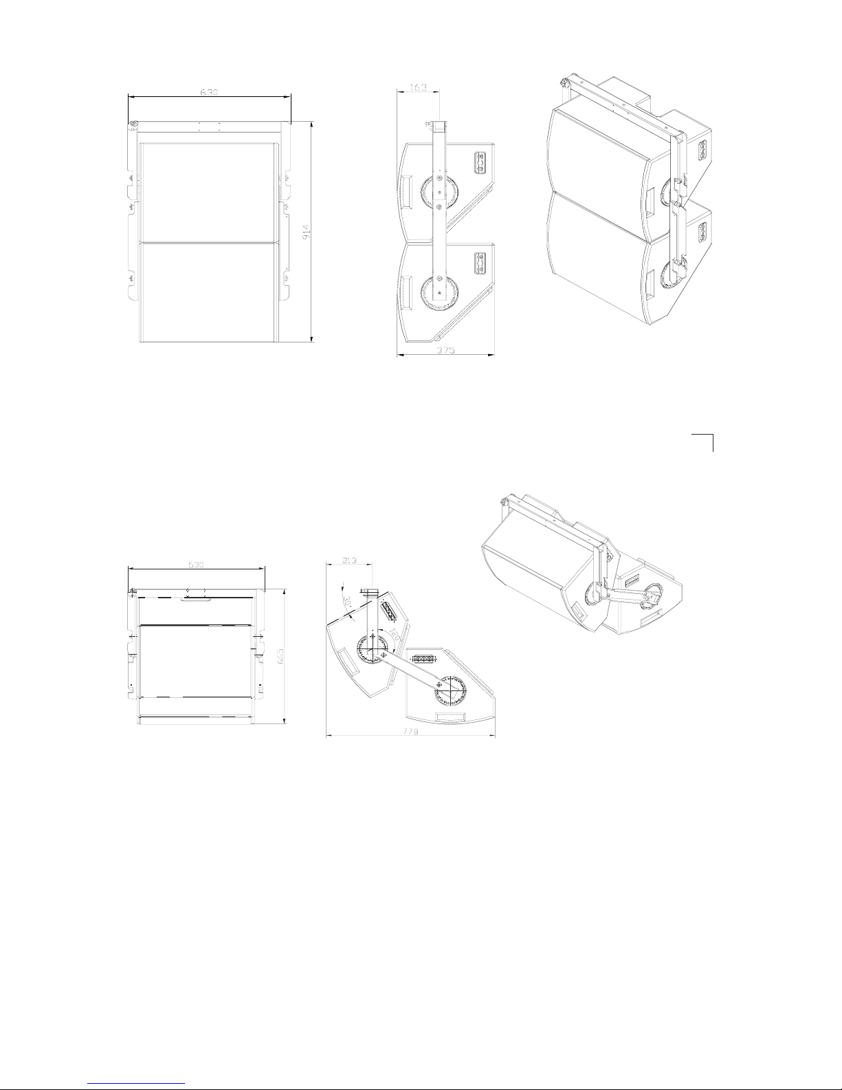
L-ACOUSTICS XT Manual V1.1 11-02-03 46
Figure 24: 112XT + ETR112XT + 112CPLXT Line Drawing (0 degree)
Figure 25: 112XT + ETR112XT + 112CPLXT Line Drawing (30 degrees)
Page 48

L-ACOUSTICS XT Manual V1.1 11-02-03 47
7.2 115XT ELEMENT SPECIFICATIONS
Frequency Response
Frequency response: 60 – 18k Hz (± 3 dB) (FRONT preset)
Usable bandwidth: 50 – 18k Hz (-10 dB)
Sensitivity
LF (2.83 Vrms at 1 m) 98 dB SPL (60 – 1k Hz)
HF (2.83 Vrms at 1 m) 108 dB SPL (1 – 18 kHz)
Power Rating Amplification Impedance
(Long Term) (recommended) (nominal)
LF 45 Vrms 250 Wrms 1000 Wpeak 500 W 8 ohms
HF 26 Vrms 85 Wrms 350 W peak 350 W 8 ohms
Nominal Directivity (-6 dB)
Axi-symmetrical 80° (± 20°)
System Output SPL
One enclosure 122 dB (cont) 128 dB (peak) FRONT preset
124 dB (cont) 130 dB (peak) FILL preset
126 dB (cont) 132 dB (peak) 3W preset
FRONT preset provides 3 dB low and high frequency contours under freefield conditions
FILL preset provides nominally flat response under freefield conditions
3W preset applies a 100 Hz high pass filter.
Components
LF 1 x 15” weather resistant loudspeaker (3” voice coil)
HF 1 x 1.4” exit compression driver (titanium diaphragm, 3” voice coil, coaxial assembly)
Enclosure
Height 580 mm 22.8 in
Front Width 440 mm 17.3 in
Rear Width 167 mm 6.6 in
Depth 475 mm 18.7 in
Trap Angle 41 degrees with respect to vertical
Net Weight 29.5 kg 65 lbs
Shipping Weight 33.2 kg 73.2 lbs
Shipping Dimensions 655 x 500 x 570 mm
25.8 x 19.7 x 22.4 in
Connectors 2x 4-pin Neutrik speakon
Material 18 mm, 30 mm Baltic birch plywood
(sealed, screwed and rabbeted angles)
Finish Maroon-gray™
Grill Black epoxy perforated steel with acoustically transparent foam
Rigging Integrated flying hardware, handles and pole mount socket
Page 49

L-ACOUSTICS XT Manual V1.1 11-02-03 48
Figure 26: 115XT Line Drawing
Page 50
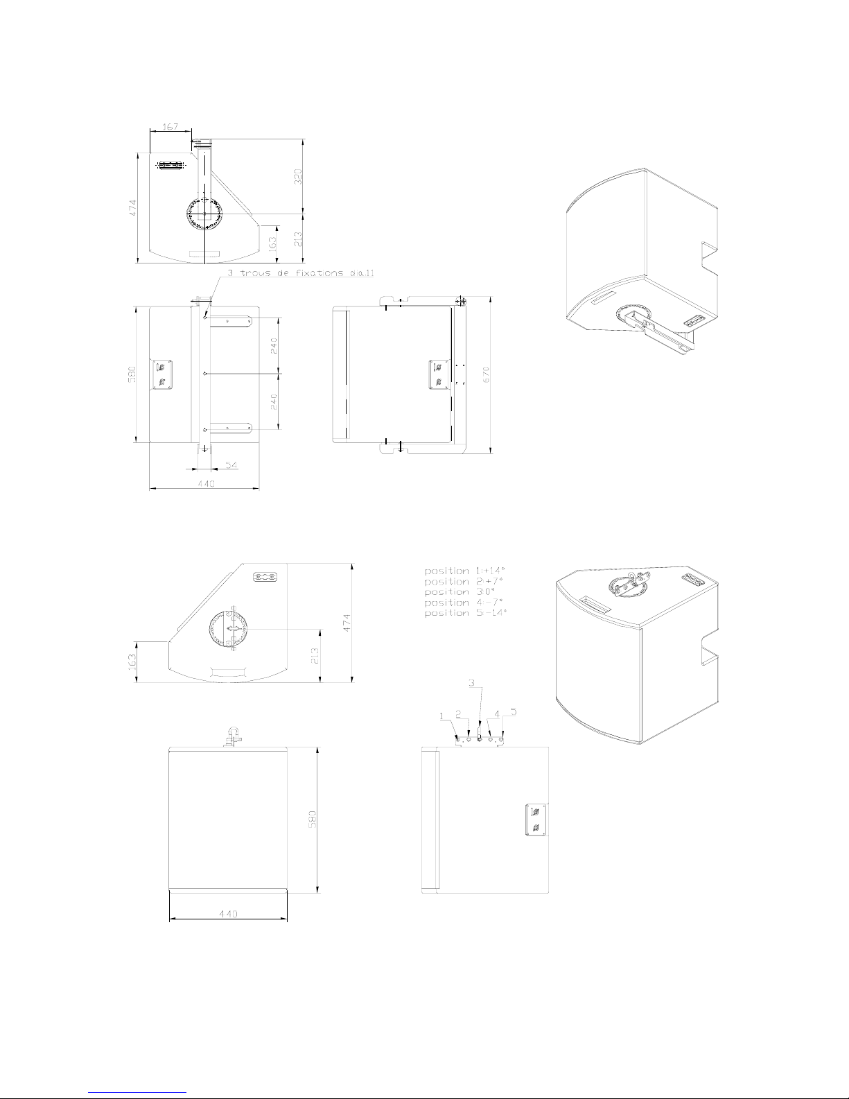
L-ACOUSTICS XT Manual V1.1 11-02-03 49
Figure 27: 115XT + ETR115XT Line Drawing
Figure 28: 115XT + XTLIFTBAR Line Drawing
Page 51
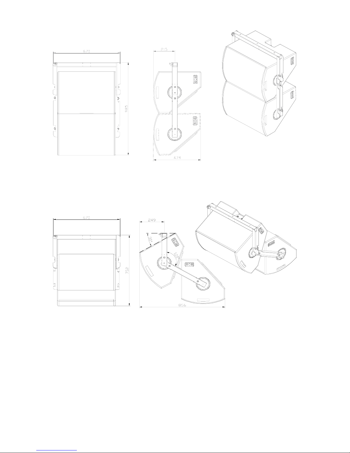
L-ACOUSTICS XT Manual V1.1 11-02-03 50
Figure 29: 115XT + ETR115XT + 115XTCPL Line Drawing (0 degrees)
Figure 30: 115XT + ETR115XT + 115XTCPL Line Drawing (30 degrees)
 Loading...