

Page 1

1
Dear Customer,
Thank you for purchasing a La Cornue cooker. We hope that you will really enjoy
preparing delicious meals with it.
The aim of this installation guide is to familiarise you with the potential of a
professional quality appliance designed for domestic use and to facilitate its upkeep.
Above all, a La Cornue cooker is manufactured from noble and pure materials. The
specific choices for certain components, such as brass for the burners and cast-iron for
the hotplate, correspond to technicality and professional performance requirements
which are not attainable with other materials or protective treatments. We are very
much attached to the authenticity of our cookers and we are convinced that you will
appreciate them even more as you use them.
We recommend you follow the advice provided in the “Instructions for Use” brochure;
this will ensure that you are satisfied with your cooker for a long time.
Thank you for placing your trust in us.
Xavier Dupuy
President and Managing Director
GRAND-MAMAN MODEL
Page 2

2
Dear Customer,
Please complete the appliance details opposite and keep them safe for future reference –
this information will enable us to accurately identify your particular appliance and help us
to help you. Filling this in now will save you time and inconvenience if you later have a
problem with your appliance. It may also be of benefit to keep your purchase receipt with
this leaflet. You may be required to produce the receipt to validate a warranty service visit.
* This information is on the appliance data badge and on the warranty certificate.
If you have a problem
In the unlikely event that you have a problem with your appliance, please refer to the rest
of this booklet and Instructions for Use, to check that you are using the appliance correctly.
If you are still having difficulty, contact your retailer.
HEADQUARTERS AND WORKSHOP
14, rue du Bois du Pont - Z.I. Les Béthunes
95310 SAINT OUEN L’AUMONE
POSTAL ADDRESS:
BP 99006 - 95070 Cergy Pontoise Cedex
FRANCE
Tel: +33 (0)1 34 48 36 36
Fax: +33 (0)1 34 64 32 65
www.lacornue.com
e-mail: a.table@la-cornue.com
LA CORNUE - Notice d’installation Europe GB - Ligne “Cornuchef” CENTENAIRE.
08NOTINSTGSC100/GB-4
September 2011 - Anna Kowalczyk
Appliance Serial Number*:
Model*:
Colour:
Fuel type*:
Tension*:
Retailers Name & Address:
Date of Purchase:
Installer's Name & Address:
Date of Installation:
Page 3

3
Notice d’installation ligne “Cornuchef” Centenaire - GB
08NOTINSTGSC100/GB-4
WARNING ................................................................................................................................ 4
DESCRIPTION .......................................................................................................................... 9
1. General description .............................................................................................................. 9
2. Energy power and gas flow rates ........................................................................................ 10
3. Power ratings for the electrical elements ............................................................................ 11
4. Rating plate ........................................................................................................................ 11
COOKER AND COOKTOP “GRAND - MAMAN 90” .............................................................. 12
1. Dimensions ........................................................................................................................ 12
2. Hob configurations ............................................................................................................. 12
3. Power for gas and electric cookers ...................................................................................... 13
4. Power for gas and electric cooktops .................................................................................... 14
5. Cooker connections ............................................................................................................ 15
6. Cooktop connections .......................................................................................................... 15
COOKER AND COOKTOP “GRAND - PAPA 135” .................................................................. 16
1. Dimensions ........................................................................................................................ 16
2. Hob configurations ............................................................................................................. 16
3. Power for gas and electric cookers ...................................................................................... 17
4. Power for gas and electric cooktops .................................................................................... 18
5. Cooker connections ............................................................................................................ 19
6. Cooktop connections .......................................................................................................... 19
COOKER AND COOKTOP “GRAND - PAPA 180” .................................................................. 20
1. Dimensions ........................................................................................................................ 20
2. Hob configurations ............................................................................................................. 20
3. Power for gas and electric cookers ...................................................................................... 21
4. Power for gas and electric cooktops .................................................................................... 22
5. Cooker connections ............................................................................................................ 23
6. Cooktop connections .......................................................................................................... 23
BEFORE DELIVERY ............................................................................................................... 24
1. Safety requirements ........................................................................................................... 24
2. Electrical supply ................................................................................................................. 25
3. Gas supply .......................................................................................................................... 26
4. Installation ......................................................................................................................... 26
CONNECTIONS ...................................................................................................................... 27
1. Electrical connections ......................................................................................................... 27
2. Gas connection ................................................................................................................... 28
IGNITION - ADJUSTMENTS .................................................................................................. 30
1. Starting with the cooktop elements ................................................................................... 30
2. Starting with the ovens ...................................................................................................... 35
3. Replacing the oven light ..................................................................................................... 36
4. Changing the injectors ....................................................................................................... 37
5. Adjusting the low settings .................................................................................................. 38
6. Injectors table ..................................................................................................................... 39
COMPLIANCE WITH EUROPEAN DIRECTIVES .................................................................... 40
WARRANTY ........................................................................................................................... 41
CONTENTS
Page 4

4
Notice d’installation ligne “Cornuchef” Centenaire - GB
08NOTINSTGSC100/GB-4
WARNING
T
his appliance must be installed by a qualified professional in accordance with the
current regulations in the country where the appliance is installed and must only be
used in a well ventilated area. Read the guides before installing and using this
appliance.
Appliance categories (see pt. 1.2, page 25 “Installation”):
- Class 1: Free-standing cooking appliance not normally in direct contact with the kitchen
units or the surrounding walls.
-Class 2: Cooking appliance that can be integrated between two kitchen units, whose walls
can be in direct contact with the surrounding units. This type of appliance can be in
contact with only one kitchen unit during installation.
- Class 2 / Sub-Class 1: Class 2 appliance that can be free-standing or installed so that the
side panels are accessible.
Before installing the appliance, ensure that the local gas supply conditions (gas
type and pressure) and the adjustment of the appliance are compatible.
The adjustment conditions for this appliance are indicated on the label at the
back of the hob and on the test certificate.
Make sure that the gas supply is turned on and that the cooker is wired in and switched
on. The cooker needs electricity.
This appliance is not intended to be connected to a ventilation system or a ventilation shaft
for combustion products. It should be installed and connected in accordance with the
current regulations, and special attention should be paid to the applicable ventilation
regulations.
The use of a gas cooking appliance results in the production of heat and moisture in the
room where it is installed. Ensure that the room is well ventilated: keep natural ventilation
holes open or install a mechanical ventilation device (mechanical extractor hood).
Prolonged or intensive use of the appliance may call for additional ventilation, e.g. by
opening a window, or for more effective ventilation, by increasing the power of the
mechanical ventilation system installed.
When you first use your cooker it may give off a slight odour. This should stop after a little
use.
The parts that are protected by the manufacturer must not be manipulated by the installer
or the user.
Read all instructions before using this appliance. Save these instructions for future reference.
Page 5

WarningWARNING
5
Notice d’installation ligne “Cornuchef” Centenaire - GB
08NOTINSTGSC100/GB-4
Please note:
The accessible parts may be hot when the oven is being used: keep young children at a safe
distance.
Children should be supervised to ensure that they do not play with the appliance.
If you smell gas:
u Don’t turn electric switches on or off.
u Don’t smoke.
u Don’t use naked flames.
u Do turn off the gas at the meter or cylinder.
u Do open doors and windows to get rid of the gas.
u Call your gas supplier.
The cooker should be serviced by a qualified service engineer and only approved spare
parts used. Have the installer show you the location of the cooker control switch. Mark it
for easy reference.
Always allow the cooker to cool and then switch off at the mains and before cleaning
or carrying out any maintenance work, unless specified otherwise in this guide or in an
“Instructions for use” guide.
All parts of the cooker become hot with use and will retain heat even after you have
stopped cooking. Take care when touching cooker, to minimize the possibility of burns,
always be certain that the controls are in the OFF position and that it is cool before
attempting to clean the cooker.
Clean with caution. If a wet sponge or cloth is used to wipe spills on a hot surface, be
careful to avoid steam burns.
Some cleansers can produce noxious fumes if applied to a hot surface.
DO NOT use a steam cleaner to clean the cooker.
Do not spray aerosols in the vicinity of the cooker while it is in on.
Do not store or use combustible materials, or flammable liquids in the vicinity of this
appliance.
Take great care when heating fats and oils, as they will ignite if they get too hot. Use
a deep fat thermometer whenever possible to prevent overheating fat beyond the smoking
point.
WARNING
Page 6

6
Notice d’installation ligne “Cornuchef” Centenaire - GB
08NOTINSTGSC100/GB-4
WARNINGWarning
Never leave a chip pan unattended. Always heat fat slowly, and watch as it heats.
Deep fry pans should be only one third full of fat. Filling the pan too full of fat can cause
spill over when food is added. If you use a combination of oils or fats in frying, stir them
together before heating, or as the fats melt.
Foods for frying should be as dry as possible. Frost on frozen foods or moisture on fresh
foods can cause hot fat to bubble up and over the sides of the pan.
Do not use the top of the flue (the slot along the back of the cooker) for warming
plates, dishes, drying tea towels or softening butter.
Take care that no water seeps into the appliance.
The oven should NOT be used for heating the kitchen, not only does this waste fuel
but the control knobs may become overheated.
When the oven is on DO NOT leave the oven door open for longer than necessary.
Before using the range make sure all the packing materials have been removed.
Destroy the carton and plastic bags after unpacking the range. Never allow children to play
with packaging material.
NEVER leave any items on the range cooktop. The hot air from an oven vent may ignite
flammable items and may increase pressure in closed containers, which may cause them
to burst.
Many aerosol-type spray cans are EXPLOSIVE when exposed to heat and may be highly
flammable.
Avoid their use or storage near an appliance.
Several types of plastic are combustible, and most of them can be damaged by heat.
Remove any objects made from paper, plastic or fabrics (such as cooking books, plastic
cooking utensils, towels, etc.) as well as flammable liquids from any parts of the range liable to get hot.
Preferably, there should be no cupboards or shelving above the appliance. In the event of
cupboards/shelving being above the appliance, make sure that they hold objects seldom
used, which can be safely kept in a place exposed to the heat generated by the appliance.
NEVER COVER the slits, apertures or holes in the bottom part of the appliance, and never
cover the grills with products such as aluminum foil; doing so would prevent air circulation inside the oven and the aluminum foil could cause heat to build up leading to a risk
of fire.
DO NOT use the oven for storage.
WARNING
Page 7

7
Notice d’installation ligne “Cornuchef” Centenaire - GB
08NOTINSTGSC100/GB-4
WarningWARNING
Flammable materials should not be stored in an oven or near the cooktop burners. This
includes paper, plastic and cloth items, such as cookbooks, plasticware and towels, as well
as flammable liquids.
NEVER TOUCH THE BURNER or the surfaces around the burner.
Note also that the burner can remain hot for a certain time even after it has been turned
off. Surfaces located around the gas burner can become sufficiently hot to cause burns.
Likewise, make sure that there is no contact between clothing and other flammable products and heating elements or appliance internal surfaces.
Wear appropriate clothing.
Do not use loose-fitting clothing (sleeves, etc.) when operating the appliance.
If there are shelves or cupboards above the appliance, be careful when reaching for products they might contain.
Flammable products can ignite on contact with a burner flame or a warm surface, leading
to serious burns.
Use only oven gloves or kitchen gloves that are dry.
Using wet gloves on warm surfaces can lead to burns caused by the vapor. Avoid all contact
between oven gloves and warm heating elements.
Never use a towel, thick cloth or similar instead of an insulating glove; they may catch fire
on contact with a hot surface.
Never operate the appliance using wet hands.
Make sure that your appliance has been correctly installed and grounded by a qualified
technician.
USE THE RIGHT SIZE PAN.
This appliance is equipped with burners of different sizes. Use utensils with flat bottoms.
Do not use unstable pans and position the handles away from the edge of the cooktop.
Make sure the flames are under the pans. It’s not safe to let the flames burn up the sides
of the pan; the handle may get too hot.
DO NOT use cooking vessels that may overlap the edges of the hotplate.
For induction hob, it is recommended not to leave any metallic utensils as knife, fork,
spoon or covers on the cooktop, as they may become hot.
WARNING
Page 8

8
Notice d’installation ligne “Cornuchef” Centenaire - GB
08NOTINSTGSC100/GB-4
Warning WARNING
The cooktop is not intended to be set on function with a timer or with a separate remote device.
All our cooking appliances are intended for domestic use only; i.e., not professional. In the event of non-domestic use, the manufacturer shall not incur any
liability, and the warranty shall be considered void.
This appliance is not intended for use by persons (including children) with reduced physical, sensory or mental capabilities, or lack of experience and knowledge, unless they have been given supervision or instruction concerning use of the
appliance by a person responsible for their safety.
All of our cooking appliance belong to Class 1 and Class 2 / Sub-Class 1. They meet the requirements of the
2009/142/CE European Directive (“Gas Appliances”), European Standard EN30 and the 2006/95/EC
European Directive (“Low Voltage Directive”).
WARNING
Page 9

9
Notice d’installation ligne “Cornuchef” Centenaire - GB
08NOTINSTGSC100/GB-4
DESCRIPTION General description
DESCRIPTION
1. GENERAL DESCRIPTION
COOKERS:
“
Grand-Maman 90”
Model GMC featuring a large vaulted
oven.
Width: 90 cm.
“
Grand-Papa 135”
Model GPC featuring a large vaulted oven
anda warming cupboard.
Width: 135 cm.
“
Grand-Papa 180”
Model GSC consisting of two large vaulted
ovens
Width: 180 cm.
COOKTOPS
“
Grand-Maman 90”
Model TCM.
Width: 90 cm.
“
Grand-Papa 135”
Model
TCC.
Width:
135 cm.
“
Grand-Papa 180”
Model
TCS.
Width:
180 cm.
The range of "CORNUCHEF" cooking appliances consists of 6 models. Each of the cooker
or hot top models includes several sub-models, depending on the chosen hot top and its
combination with the oven.
The cookers in the "CORNUCHEF" range consist of:
- a thermostatically-controlled electric or gas oven or 2 ovens;
- one hot top bounded at the rear by a stainless steel skirting creating a gap between the
cooker and the wall, thus ensuring the removal of burnt gases and smells.
Page 10

10
Notice d’installation ligne “Cornuchef” Centenaire - GB
08NOTINSTGSC100/GB-4
DESCRIPTIONEnergy power
All of our appliances belong to Category II and are designed for gases from the second and
third groups.
The gas used can be either natural gas, propane or butane, depending on availability. Refer
to pages 37 – 39 for information about adapting your cooker or your hob to the various
types of gas.
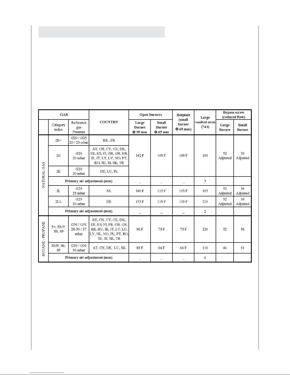
The tables below summarise for each gas type and for each burner the heat flow rate
(energy power in kW, Gross Calorific Value) and the volume flow rate (in m3/hour) or the
mass flow rate (in kg/hour) of useful gas.
NOMINAL HEAT INPUT
REDUCED HEAT INPUT
2. ENERGY POWER AND GAS FLOW RATES
Page 11
11
Notice d’installation ligne “Cornuchef” Centenaire - GB
08NOTINSTGSC100/GB-4
DESCRIPTION Energy power
Large vaulted electric oven (74 litres, large volume) ............................................... 6 000 W
3 500 W oven floor + 2 500 W vault
Grill in large vaulted gas oven ..............................................................................… 2 500 W
Baking stone ............................................................................................................ 3 000 W
Oven light ..................................................................................................................... 25 W
Ignition for large vaulted gas oven ............................................................................... 25 W
Automatic ignition for gas burners ............................................................................... 25 W
Warming cupboard, width: 450 mm ....................................................................… 1 750 W
Electric ceramic hob, Ø 145 mm .............................................................................. 1 200 W
Electric ceramic hob, Ø 180/110 mm (2 zones) ............................................. 1 700 / 700 W
Induction plates (2 burners: Ø 145 mm and Ø 180 mm) ....................................… 3 700 W
Round electric plate, Ø 180 mm .............................................................................. 2 000 W
Round electric plate, Ø 220 mm .............................................................................. 2 000 W
Electric hotplate ..........……………………………..................................................... 1 300 W
(small, dimensions: 284 x 476 mm)
Small “La Cornue” Teppan-Yaki .................................................….......................... 1 600 W
(dimensions: 284 x 478 mm)
Large “La Cornue” Teppan-Yaki .............................................................................. 2 000 W
(dimensions: 419 x 478 mm)
Large induction plate (burner Ø 280 mm) ..........................…................................. 3 700 W
Large induction Wok (burner Ø 300 mm) .......................….................................... 3 000 W
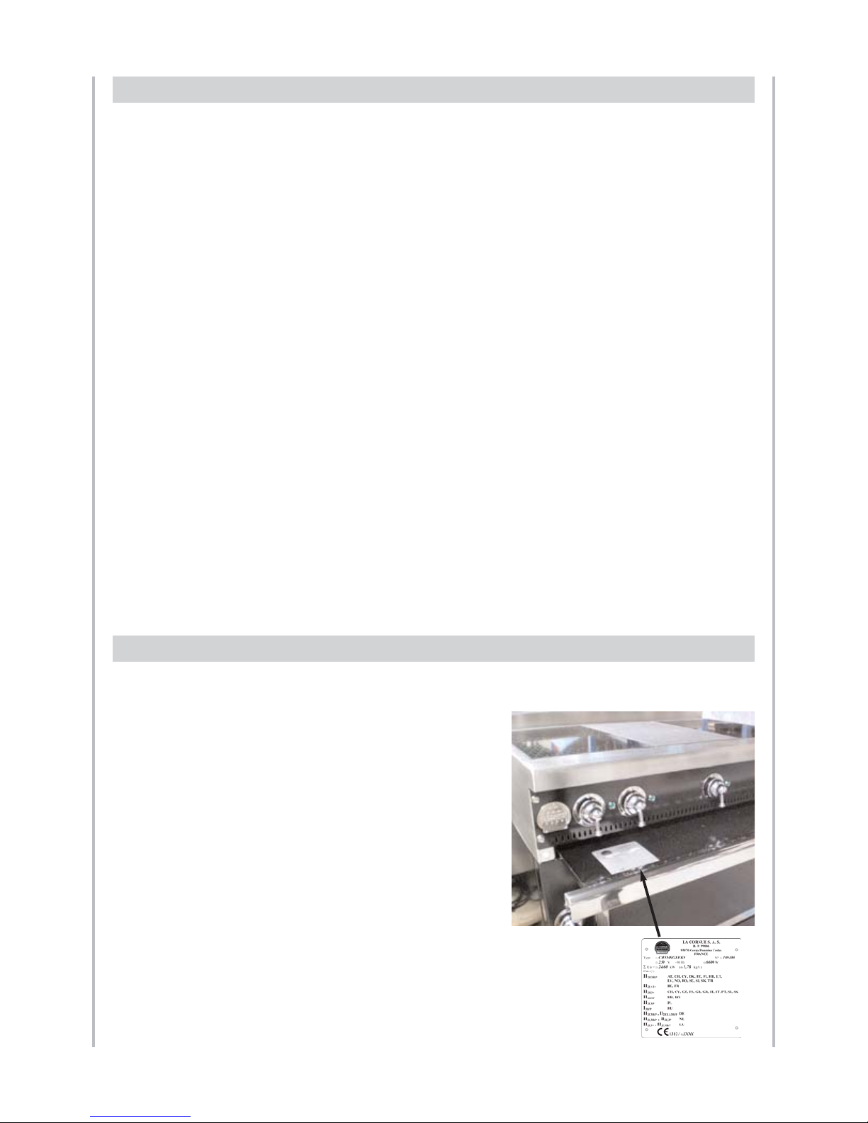
The rating plate of your appliance is on inside the spill
tray. To see this rating plate, pull out the spill tray.
You will find on this plate the name and address of the
manufacturer as well as the following information:
1) Kind of appliance (model)
2) Serial number (order number) and the manufacture date
3) Voltage rating in Volt (AC)
4) Power assigned (Watt), including power of the
induction hob (if applicable)
5) ΣQn: Total heat input of gas in kW (gross calorific value)
6) Mass flow rate - Butane and Propane Gas only
7) Appliance category
8) CE approval number
3. POWER RATINGS FOR THE ELECTRICAL ELEMENTS
4. RATING PLATE
Page 12

12
Notice d’installation ligne “Cornuchef” Centenaire - GB
08NOTINSTGSC100/GB-4
DESCRIPTIONGrand - Maman 90
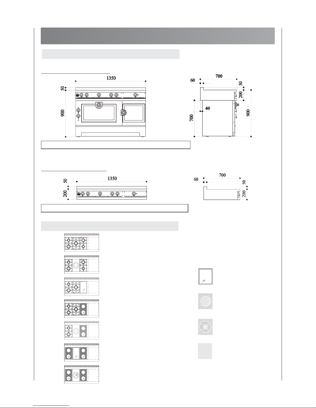
COOKER AND COOKTOP GRAND - MAMAN 90
1. Cooker (model GMC):
Cooktop (model TCM):
1. DIMENSIONS
Cooktop weight: 70 - 90 kg. depending on the model
2 electric induction plates
1 electric hotplate
2 electric induction plates
M0
M1
M2
M3
M4
MA
MB
Cooker weight: 110 - 150 kg. depending on the model
2. HOB CONFIGURATIONS
2 gas burners (small burner at the rear)
1 single gas burner
2 gas burners (small burner in front)
2 gas burners (small burner at the rear)
1 gas hotplate
2 gas burners (small burner in front)
2 gas burners (small burner at the rear)
1 single gas burner
2 electric induction plates
2 gas burners (small burner at the rear)
1 gas hotplate
2 electric induction plates
2 gas burners (small burner at the rear)
1 single gas burner
1 small electric teppan-yaki
2 electric induction plates
1 small electric teppan-yaki
2 electric induction plates
Page 13

13
Notice d’installation ligne “Cornuchef” Centenaire - GB
08NOTINSTGSC100/GB-4
DESCRIPTION Grand - Maman 90
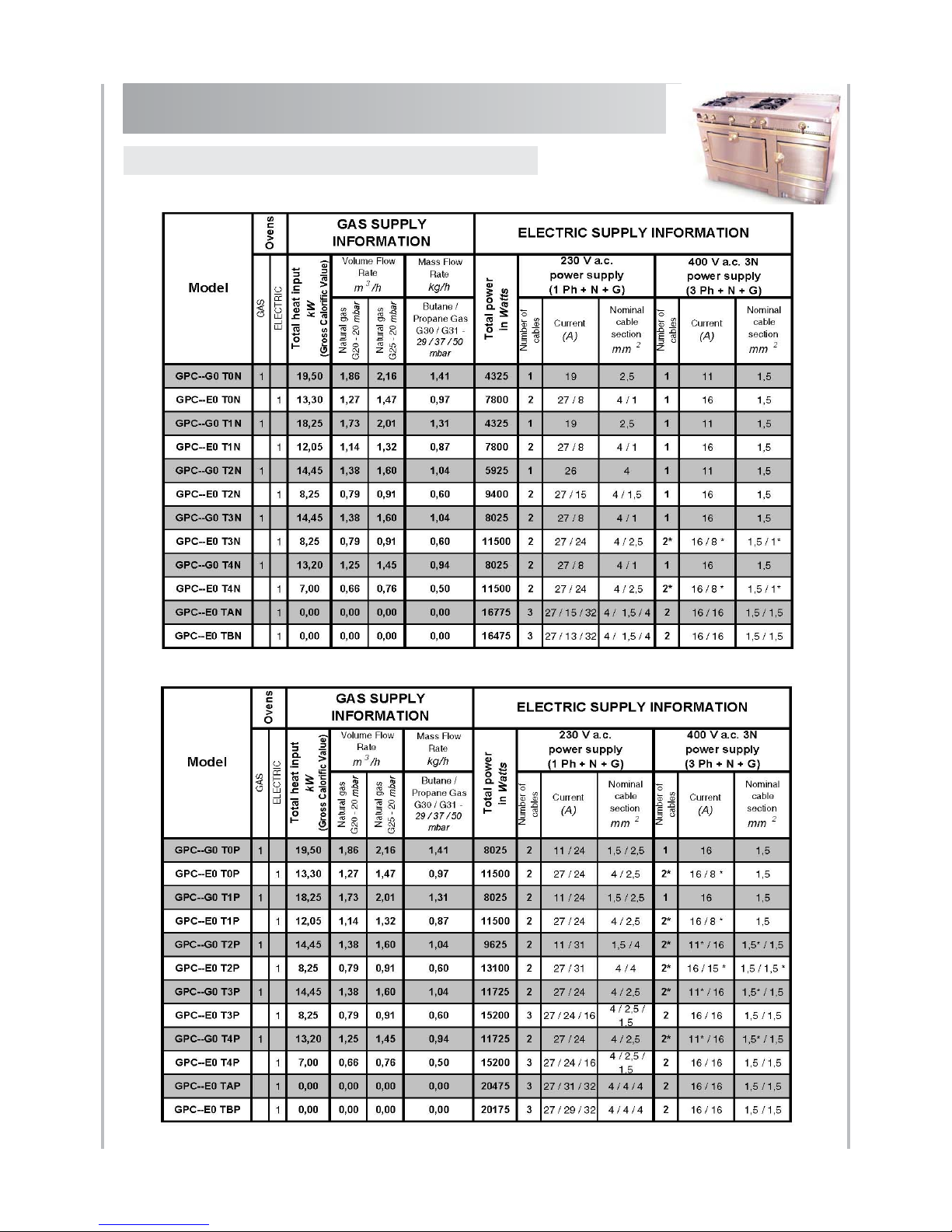
3. POWER FOR GAS AND ELECTRIC COOKERS
COOKER GRAND - MAMAN 90
Page 14

4. POWER FOR GAS AND ELECTRIC COOKTOPS
GRAND - MAMAN 90
DESCRIPTIONGrand - Maman 90
Notice d’installation ligne “Cornuchef” Centenaire - GB
08NOTINSTGSC100/GB-4
14
Page 15

Mixed gas/electric cooker
All-electric cooker
Mixed or all-gas cooktop
All-electric cooktop
6. COOKTOP CONNECTIONS
5. COOKER CONNECTIONS
15
Notice d’installation ligne “Cornuchef” Centenaire - GB
08NOTINSTGSC100/GB-4
DESCRIPTION Grand - Maman 90
GRAND - MAMAN 90
Rear view
Rear view
Rear view
Rear view
TERMINAL
BLOCK 2
TERMINAL
BLOCK 1
GAS INLET
MALE G 1/2
CONNECTION
GAS INLET
MALE G 1/2
CONNECTION
TERMINAL
BLOCK 2
TERMINAL
BLOCK 1
TERMINAL
BLOCK 1
TERMINAL
BLOCK 1
TERMINAL
BLOCK 2
GAS INLET
MALE G 1/2
CONNECTION
GAS INLET
MALE G 1/2
CONNECTION
Page 16
Cooker and Cooktop GRAND - PAPA 135
16
Notice d’installation ligne “Cornuchef” Centenaire - GB
08NOTINSTGSC100/GB-4
DESCRIPTION
1. Cooker (model GPC):
Cooktop (model TCC):
1. DIMENSIONS
2. HOB CONFIGURATIONS
Cooktop weight: 80 - 100 kg. depending on the model
2 gas burners (small burner at the rear)
1 single gas burner
2 gas burners (small burner in front)
+ option
2 gas burners (small burner at the rear)
1 gas hotplate
2 gas burners (small burner in front)
+ option
2 gas burners (small burner at the rear)
1 single gas burner
2 electric induction plates
+ option
2 gas burners (small burner at the rear)
1 gas hotplate
2 electric induction plates
+ option
2 electric induction plates
1 electric hotplate
2 electric induction plates
+ option
2 gas burners (small burner at the rear)
1 single gas burner
1 small electric teppan-yaki
+ option
2 electric induction plates
1 small electric teppan-yaki
2 electric induction plates
+ option
T
Large electric teppan-yaki
P
Large electric induction plate
W
Large electric induction WOK
N
Stainless steel countertop
Grand - Papa 135
T0
T1
T2
T3
T4
TA
TB
OPTIONS GRAND - PAPA 135
Cooker weight: 180 - 220 kg. depending on the model
Page 17
Cooker Grand - Papa 135 with “Stainless steel countertop”
Cooker Grand - Papa 135 with option “Large Induction Plate”
17
Notice d’installation ligne “Cornuchef” Centenaire - GB
08NOTINSTGSC100/GB-4
DESCRIPTION Grand - Papa 135
3. POWER FOR GAS AND ELECTRIC COOKERS
Cooker GRAND - PAPA 135
* PLEASE NOTE: For 2 cables and a 400 V a.c. 3N power supply (3 Ph + N + T):
- 1 cable is 400 V a.c., 3-PHASE
- 1 cable is 230 V a.c., SINGLE-PHASE
Page 18

Cooktop Grand - Papa 135 with “Stainless steel countertop”
Cooktop Grand - Papa 135 with option “Large Induction Plate”
18
Notice d’installation ligne “Cornuchef” Centenaire - GB
08NOTINSTGSC100/GB-4
DESCRIPTION
4. POWER FOR GAS AND ELECTRIC COOKTOPS
Grand - Papa 135
Cooktop GRAND - PAPA 135
* PL EA SE N OT E: For 2 cables and a 400 V a.c. 3N power supply (3 Ph + N + T):
- 1 cable is 400 V a.c., 3-PHASE
- 1 cable is 230 V a.c., SINGLE-PHASE
Page 19

Mixed gas/electric cooker
All-electric cooker
Mixed or all-gas cooktop
All-electric cooktop
6. COOKTOP CONNECTIONS
5. COOKER CONNECTIONS
19
Notice d’installation ligne “Cornuchef” Centenaire - GB
08NOTINSTGSC100/GB-4
DESCRIPTION
Rear view
Rear view
Rear view
Rear view
TERMINAL
BLOCK 3
TERMINAL
BLOCK 1
TERMINAL
BLOCK 2
TERMINAL
BLOCK 3
TERMINAL
BLOCK 2
TERMINAL
BLOCK 1
GAS INLET
MALE G 1/2
CONNECTION
TERMINAL
BLOCK 1
TERMINAL
BLOCK 1
GAS INLET
MALE G 1/2
CONNECTION
GAS INLET
MALE G 1/2
CONNECTION
Grand - Papa 135
GRAND - PAPA 135
GAS INLET
MALE G 1/2
CONNECTION
TERMINAL
BLOCK 2
Page 20
20
Notice d’installation ligne “Cornuchef” Centenaire - GB
08NOTINSTGSC100/GB-4
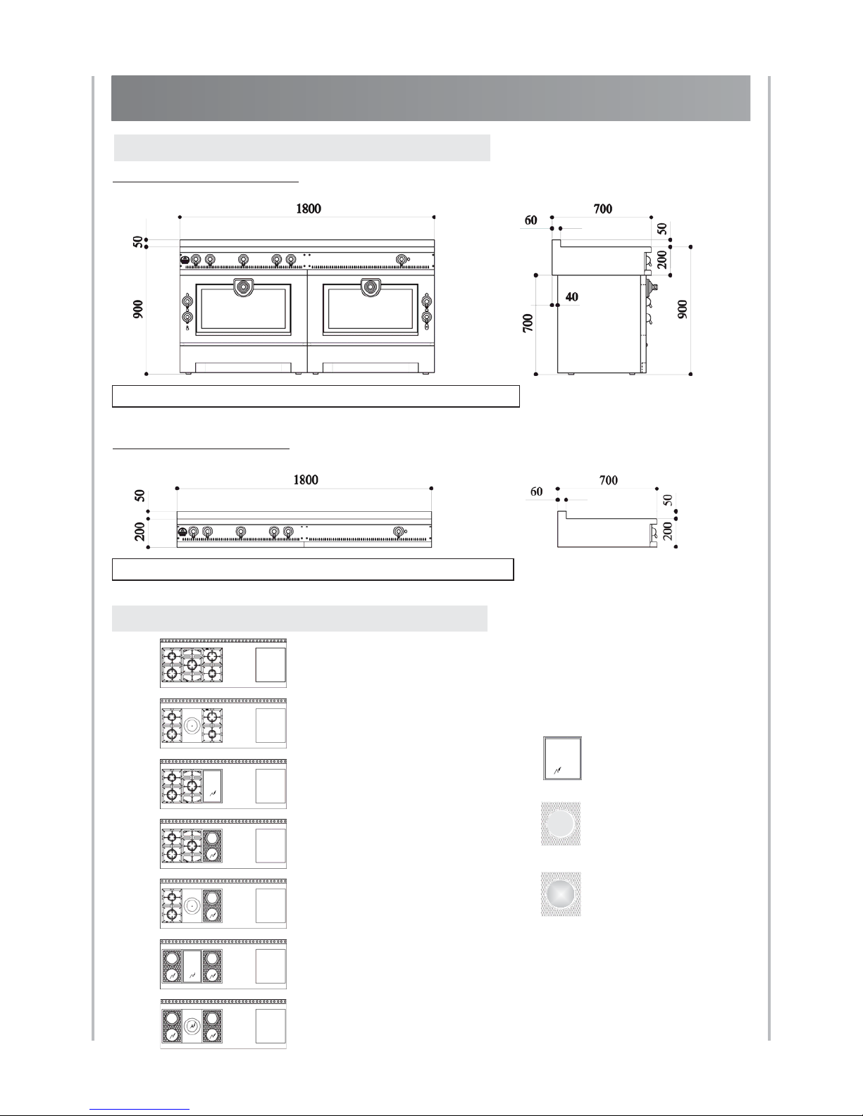
DESCRIPTION
1. Cooker (model GSC):
Cooktop (model TCS):
1. DIMENSIONS
2. HOB CONFIGURATIONS
Cooktop weight: 100 - 130 kg. depending on the model
2 gas burners (small burner at the rear)
1 single gas burner
2 gas burners (small burner in front)
+ option
2 gas burners (small burner at the rear)
1 gas hotplate
2 gas burners (small burner in front)
+ option
2 gas burners (small burner at the rear)
1 single gas burner
2 electric induction plates
+ option
2 gas burners (small burner at the rear)
1 gas hotplate
2 electric induction plates
+ option
2 electric induction plates
1 electric hotplate
2 electric induction plates
+ option
S0
S1
S2
S3
S4
SA
SB
2 gas burners (small burner at the rear)
1 single gas burner
1 small electric teppan-yaki
+ option
OPTIONS GRAND - PAPA 180
2 electric induction plates
1 small electric teppan-yaki
2 electric induction plates
+ option
T
Large electric teppan-yaki
P
Large electric induction plate
W
Large electric induction WOK
Grand - Papa 180
Cooker and Cooktop GRAND - PAPA 180
Cooker weight: 280 - 320 kg. depending on the model
Page 21
Cooker Grand - Papa 180 with option “Large Induction Plate”
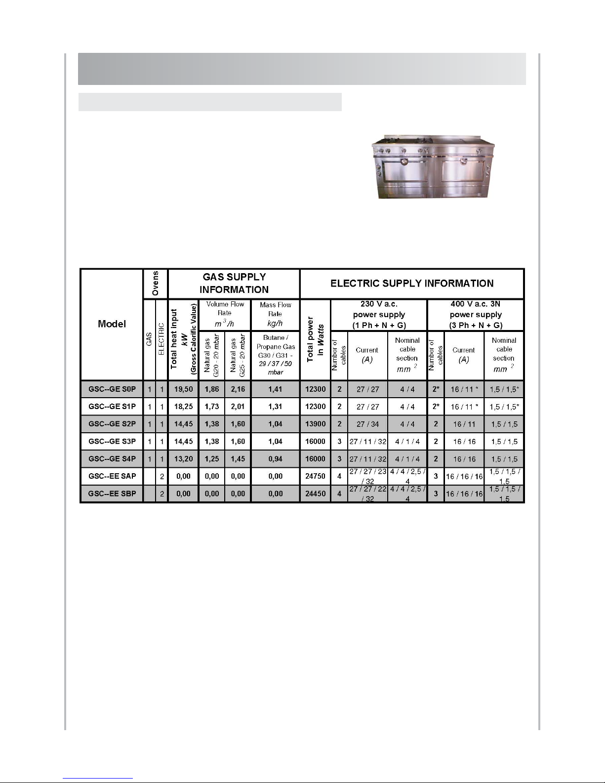
* PLEASE NOTE: For 2 cables and a 400 V a.c. 3N power supply (3 Ph + N + T):
- 1 cable is 400 V a.c., 3-PHASE
- 1 cable is 230 V a.c., SINGLE-PHASE
Cooker GRAND - PAPA 180
21
Notice d’installation ligne “Cornuchef” Centenaire - GB
08NOTINSTGSC100/GB-4
DESCRIPTION
3. POWER FOR GAS AND ELECTRIC COOKERS
Grand - Papa 180
Page 22
22
Notice d’installation ligne “Cornuchef” Centenaire - GB
08NOTINSTGSC100/GB-4
DESCRIPTION
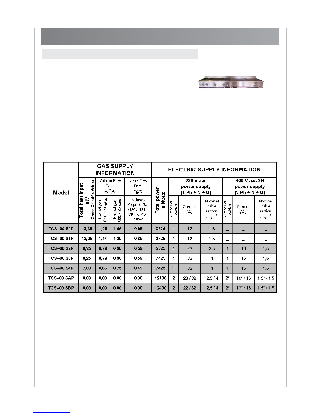
4. POWER FOR GAS AND ELECTRIC COOKTOPS
Cooktop Grand - Papa 180 with option “Large Induction Plate”
* PLEASE NOTE: For 2 cables and a 400 V a.c. 3N power supply (3 Ph + N + T):
- 1 cable is 400 V a.c., 3-PHASE
- 1 cable is 230 V a.c., SINGLE-PHASE
Grand - Papa 180
Cooktop GRAND - PAPA 180
Page 23

Mixed gas/electric cooker
All-electric cooker
Mixed or all-gas cooktop
All-electric cooktop
6. COOKTOP CONNECTIONS
5. COOKER CONNECTIONS
23
Notice d’installation ligne “Cornuchef” Centenaire - GB
08NOTINSTGSC100/GB-4
DESCRIPTION
TERMINAL
BLOCK 3
TERMINAL
BLOCK 3
TERMINAL
BLOCK 4
Rear view
Rear view
Rear view
Rear view
TERMINAL
BLOCK 1
TERMINAL
BLOCK 2
TERMINAL
BLOCK 1
TERMINAL
BLOCK 2
GAS INLET
MALE G 1/2
CONNECTION
GAS INLET
MALE G 1/2
CONNECTION
Grand - Papa 180
GRAND - PAPA 180
TERMINAL
BLOCK 1
GAS INLET
MALE G 1/2
CONNECTION
GAS INLET
MALE G 1/2
CONNECTION
TERMINAL
BLOCK 1
TERMINAL
BLOCK 2
Page 24

24
Safety BEFORE DELIVERY
Notice d’installation ligne “Cornuchef” Centenaire - GB
08NOTINSTGSC100/GB-4
In order to be able to install your appliance as soon as it is delivered, you must check that
the layout of your kitchen and your gas and electricity supplies are adapted.
All gas and electrical installations must comply with the standards and current
regulations in the country where the appliance is installed, as well as with the
requirements of local gas and electricity suppliers.
In the event of the cooker being installed by us, our technicians may ask you for a certificate proving that your domestic installation is compliant.
The manufacturer shall not incur any liability for an incorrect installation, and incorrect
installations shall void the warranty. Moreover, no legal actions can be undertaken in relation to incorrect installations.
1.1. Ventilation
Special care should be taken to respect the regulation in force regarding ventilation. All requirements and regulations in force regarding the ventilation of rooms
where gas appliances are installed, should be respected.
It is essential that the room where the “La Cornue” cooker or hob will be installed has
excellent ventilation, i.e. to the outside for vapour and burnt gases and a fresh air inlet.
Do not use an air recycling system.
A flow rate of at least 4 cubic metres per hour of fresh air per kW of gas heat power is
necessary to ensure the supply of combustion air.
You should take into account all appliances using gas installed in the room; additional ventilation may be necessary.
The gas regulations also require high and low ventilation to be installed in the room where
a gas appliance will be installed.
The external ventilation system must consist of fixed aerators or flipping glass panes as
well as vapour aspirators or extractor hoods.
We strongly advise you to use an extractor hood.
Recommended power:
- minimum of 1 400 cubic metres per hour for “Grand Papa 180”.
- 700 cubic metres per hour for “Grand Papa 135” and “Grand-Maman 90”
or 10 – 15 times the volume of the air in the room each hour.
"La Cornue" can propose you models of customized hoods in materials matching your
cooker or extractors that can be integrated into a hood manufactured by the user.
1. SAFETY
BEFORE DELIVERY
Page 25

25
Electrical SupplyBEFORE DELIVERY
The ventilation hood has to be built with non-combustible materials.
For optimum efficiency, the fresh air inlet for renewing the air extracted by the hood must
be located within a 2 – 3 m. radius, at ground level.
1.2. Installation (see drawing below)
As the oven and the hob are particularly well insulated, the appliance can be built-in
without any need for any special precautions with regard to the surroundings. However,
if the cooker or the cooktop is installed against a wall, the hottest parts (the strip
between 60 and 95 cm. from the floor, and the surface between the cooktop and
the extractor hood) must be protected with a stainless steel plate or ceramic
tiles. La Cornue is able to offer you several backsplash (stainless steel plate) at dimensions
according to your stove
Ceramic cardboard with a minimum thickness of 20 mm. must be installed under
the cooktop to insulate the units placed underneath.
MINIMUM DISTANCE FROM THE KITCHEN UNITS (in mm.)
Voltage:
220 - 240 V a.c., single-phase + neutral + ground
400 V a.c. 3N, three-phase + neutral + ground.
Safety:
The electrical supply must necessarily be grounded and must be equipped with
a circuit breaker protection compatible with the appliance’s power rating.
When a cooker is hooked on 400 V tri-phase, the circuit breaker must be a 4-line breaker
(3 phases and neutral must be cut).
In high-risk regions, an additional protection against natural electrical phenomena
(lightning) must be used.
A disconnection system must be provided in accordance with standard regulation.
2. ELECTRICAL SUPPLY
300 300
0
0
0
330
450
A
A
minimum 750
recommandé 900
Notice d’installation ligne “Cornuchef” Centenaire - GB
08NOTINSTGSC100/GB-4
RECOMMENDED 900
MINIMUM 750
Page 26

26
Notice d’installation ligne “Cornuchef” Centenaire - GB
08NOTINSTGSC100/GB-4
Gas supply BEFORE DELIVERY
Power:
It is advisable to check whether the power rating of your electrical installation provides
you with sufficient power for your model, taking into account any electrical appliances
you have already installed. Refer to the tables for each of the models for the total power
and current ratings.
Due to the power of La Cornue appliances, a simple plug and socket connection is not
recommended: the electrical connection should consist of a flexible cord without a plug,
directly connected to the circuit breaker outlet by means of a junction box with terminal
blocks, preferably of the anti-shearing type.
Only all-gas hobs with only hob burner ignition can be connected with an ordinary 3-pin
plug.
The gas installation must comply with the current regulations in the country
where the appliance will be installed.
Reminder of the main obligations with regard to gas installations:
The gas must be supplied via a rigid metallic pipe, terminated by an easily accessible
manual shutoff valve.
This valve must be positioned, taking into account that the gas inlet on the appliance is
situated:
· on the left of the cooker or the cooktop.
· at the level of the work area (on the bottom left) for cooktop.
See the drawings on the specific presentation pages for each model for details about the
connections.
When your cooker or your cooktop is built-in between two kitchen units, the shut-off
valve must be accessible through an appropriate cut-out in the back of the kitchen unit.
It is forbidden to use flexible rubber hoses with a collar fastening to supply gas to gas
appliances.
When all of the work has been carried out on your gas supply network, perform a
functional test before connecting the appliance; this will ensure that no metallic burrs can
enter the appliance’s gas supply pipe and thus obstruct the burners or the gas taps.
Also, perform mechanical resistance and sealing tests in accordance with the applicable
standards.
In order to ensure that the cooktop is perfectly horizontal, especially on old flooring, we
advise you to install your cooker on a wooden or cement base and your hob on a perfectly
horizontal kitchen unit, the height of which will allow you to bring the hob to a level in
4. INSTALLATION
3. GAS SUPPLY
Page 27

27
Electrical connectionsCONNECTIONS
accordance with its environment or your own requirements.
Each cooker is equipped with adjustable feet that allow you to compensate for differences
in the floor level.
REMINDER: Ceramic cardboard with a minimum thickness of 20mm. must be
installed under the cooktop to insulate the units placed underneath.
" La Cornue " appliances are supplied with 1 – 4 flexible cords, P/N: H07 RN-F, consisting
of 3 or 5 wires, approximately 1.5 m long, ready to be connected to a single-phase or 3phase + neutral + ground power supply, depending on the indications specified on the
order form (see the table corresponding to each model for the power ratings).
If the wire is damaged, it must be replaced by the manufacturer, its after sales
services or qualified persons in order to avoid hazard.
All of the electricity supply circuits must be disconnected before accessing the
connection terminal boxes.
REMINDER: the appliance should be connected to the main power supply via terminal
blocks and not by means of simple plugs.
Insert the cable below the hot air outlets at the back of the oven, never in front of them.
Should your appliance be connected to a different type of power supply at a later date, in
some cases (please contact our technical department before) it will be possible to change
the cabling accordingly, according to the following instructions:
- Unscrew the protection plate from the back of the appliance in order to access the
connection terminal block(s) to which the various heating elements are connected (if
there are 2, 3 or 4 supply cables on the cooker, there are also 2, 3 or 4 connection terminal
blocks).
220 - 240 V – single-phase 400 V – 3-phase
- For a single-phase 220 - 240 V power supply, shunt the P1, P2 and P3 terminals,
and then connect the cable wires as follows:
- neutral (blue wire) to N
1. ELECTRICAL CONNECTIONS
CONNECTIONS
Notice d’installation ligne “Cornuchef” Centenaire - GB
08NOTINSTGSC100/GB-4
T = Ground
N = Neutral
Ph1 = Phase 1
Ph2 = Phase 2
Ph3 = Phase 3
Page 28

- the phase (red or brown wire) to P1
- the ground to T (yellow / green)
- For a 3-phase 400 V power supply, remove the shunt from the P1, P2 and P3
terminals, and then connect the cable wires as follows:
- neutral (blue wire) to N
- the three other wires (red or brown) to the P1, P2 and P3 terminals.
- the ground to T (yellow / green)
Ensure that the cross-section of the electrical cables corresponds to that
indicated in the tables in the general description for each appliance.
Our appliances are supplied with injectors corresponding to the type of gas supply specified
in your order (natural gas, butane or propane) and according to the country where the
cooker is to be installed.. These injectors should only be changed if a different type of gas
is used.
However, it may be necessary to adjust or change the “by-pass” screw. See page 39 for the
table summarizing the injectors to be used for each type of gas, the country of installation
and injector replacement instructions.
If no particular instructions are specified in the order, the appliance is equipped with
injectors for natural gas G20 (pressure: 20 mbar).
The type of gas for which the appliance is equipped, is indicated on a label at the rear
of the appliance, near the gas supply pipe.
The gas connection must be done in keeping with the installation rules in force
in the country where the appliance is to be used.
Connection to the previously installed shut-off valve must be made using a flexible hose
with screwable connectors, approved.
The characteristics of this hose must be tailored to the nature and distribution mode of the
gas used, as well as to the diameter of the connection used.
The hose must not pass behind, in front of or close to a hot air outlet. It must be put down
so as not to be reachable by flames. It must not be crushed or kinked, and must be put
down so as to avoid all pulling stress.
The hose must be firmly attached at both ends, and it must be possible to inspect the complete hose length. Moreover, the hose should be replaced by the user whenever required
and, in all cases, before the maximum use date given on the hose.
Recommended use: metallic flexible hose (stainless steel surrounded by metallic
braids) with screwable connectors, without any lifetime end date.
Regardless of the gas used, it is forbidden to connect our gas appliances with flexible hoses
mounted on rubber tail pieces.
2. GAS CONNECTION
28
Notice d’installation ligne “Cornuchef” Centenaire - GB
08NOTINSTGSC100/GB-4
CONNECTIONSGas connection
Page 29

29
CONNECTIONS Gas connection
The appliance is delivered with a threaded coupling. The cylindrical external threading has a
gas thread of “G ½ A”, in accordance with the
EN ISO 228-1:2003 standard. This type of
connection is used in France and some
European countries.
If you use an “R ½” external conic coupling in
accordance with the EN 10226-1:2004 and EN
10226-2:2005 standards or an “Rp ½” internal
cylindrical coupling as per the EN 102261:2004 standard, then unscrew the adapter on
the appliance and either turn it around, or
connect your hose directly to the end of the
tubing.
Screw the gas hose at the end of the appliance tubing, tightening it only by hand. Place
two appropriate tools (one on the tubing to keep it from moving, and the other on the
hose coupling) and tighten the coupling on the hose.
Assemble the hose so that the hose is left hanging in a “U” form.
When the connection is terminated, perform a pressure test to check the sealing of the
appliance. When checking the sealing, make sure not to use washing-up liquid, which
could damage the appliance; instead, use a foam liquid specially intended to detect leaks.
Sealing must be ensured by tightening 2 sealing surfaces beyond the threading with an
appropriate sealing joint between them. To ensure the correct level of sealing along the
threading, a sealing compound or joining compound should be applied to the threading.
If a sealing compound has to be used, we recommend LOCTITE 542.
To locate the gas and electric supply on your appliance, please refer to the drawings on the pages of the description corresponding to the appliance.
For appliances operating with BUTANE / PROPANE gas, use two cylinders with an automatic reversing switch or an outdoor tank, and a standard pressure regulator adapted to
the total flow rate for your model and the gas pressure.
We advise you to use a pressure reducing valve with a minimum of 2 kg./hour for the hobs
and a pressure reducing valve with a minimum of 3 kg./hour for the other models.
As a general rule, an additional safety margin corresponding to 20 – 30% of the appliance’s maximum flow rate must be respected.
To guarantee constant pressure from the gas supply, the pressure regulator should not be
placed more than 2 m from the appliance.
Each appliance must have its own pressure regulator.
Notice d’installation ligne “Cornuchef” Centenaire - GB
08NOTINSTGSC100/GB-4
Rp 1/2
R 1/2
G 1/2 A
Page 30

Starting with the cooktop elements
30
Notice d’installation ligne “Cornuchef” Centenaire - GB
08NOTINSTGSC100/GB-4
The gas burners on our “Cornuchef” range appliances are fitted with safety thermocouples:
if a burner shuts off for any reason, the gas supply for that burner is automatically stopped.
The thermocouple should not be activated for more than 15 seconds; if, after this time, the
burner has not ignited, you should stop trying to ignite, and wait at least one minute before trying to reignite the burner.
1.1. Gas hobs with electric ignition (small and large burner)
All of our appliances are originally equipped with automatic gas
burner ignition.
To ignite a gas burner, press the control knob and turn it to the left
to the “high flame” position.
The burner is automatically ignited. Keep the knob pressed for 5 –
10 seconds (the safety thermocouple may take longer to react the
first time without however exceeding 15 seconds).
The sparking noise means that the ignition system is operating
normally.
· Low setting: this is achieved by rotating the knob fully to the left or to the bottom.
· Shutoff: bring the knob back to its vertical position by rotating it to the right.
In case the burner flame is accidentally turned off, close the burner control knob and do
not turn on the burner for at least one minute.
In case the burner flame is accidentally turned off, close the burner
control knob and do not turn on the burner for at least one minute.
1.2. Gas Hotplate
Ignition identical to that for gas burners.
INITIAL IGNITION
Defuse any trapped air from the gas network, starting with each of the burners on
the cooktop. Once this is done, the gas oven can then be ignited. However, if the
safety device for the oven is activated (red indicator ON), press the reset button
above the red indicator to repeat the procedure.
1. STARTING WITH THE COOKTOP ELEMENTS
IGNITION – ADJUSTMENTS
IGNITION – ADJUSTMENTS
Page 31

IGNITION – ADJUSTMENTS
31
Notice d’installation ligne “Cornuchef” Centenaire - GB
08NOTINSTGSC100/GB-4
Starting with the cooktop elements
1.3. Round ceramic plates
Warning: if the surface is cracked, immediately disconnect the device or the power supply.
To heat a ceramic plate with a single burner (diameter: 145 mm), turn
the knob towards the right or towards the left to the desired
position:
- 1 corresponds to the lowest position,
- 6 corresponds to the highest position,
- 0 corresponds to the shutoff position.
To heat the central burner of a ceramic plate with a double
burner - 2 zones (diameter: 180/110 mm), you just have to
rotate the double-circuit simmerstat clockwise.
To ignite the 2 (outer and central) burners, turn the knob
towards the right to the sign
oo (see the figure shown opposite) until
you hear a click from the microswitch that will light the peripheral
element.
The two burners reach the maximum temperature in this position. You can then set the
temperature of the double burner by turning the control knob to any position between 6
and 1.
Note: it is impossible to only ignite the outer burner.
The vitroceramic plates have 3 indicator lights: one at the bottom left - these come on
when a hob control is turned on and two indicator lights of residual heat (one for each
cooking areas) in the bottom right.
As long as the symbol of residual heat is on, do not touch the cooking areas and
do not place anything sensitive to heat on the ceramic glass.
1.4. Induction ceramic Hob
Induction heats up food and liquids very quickly; take care until you are familiar with it.
Warning: if the surface is cracked, immediately disconnect the device or the power supply
After use, stop the induction hob with its control knob; do not just rely on the pan detection
device.
WARNING: EVEN WHEN THE INDICATORS GO OUT, THE SURFACE MAY NOT
HAVE COOLED COMPLETELY.
DO NOT place plastic or aluminium foil, or plastic containers, on the induction
plates.
Protection in case of overheating: the cooker is protected by a thermal safety device
that makes it momentarily unusable in case of overheating (such as when forgetting an
empty pan). Overheating causes the message “E2” to be displayed and the cooker to no
longer heat up. Once the temperature has returned to normal, the “E2” message
disappears. It will then be possible to control the cooker again.
0
3
1
2
4
5
6
0
3
1
2
4
5
6
single burner
double burner
Page 32
IGNITION – ADJUSTMENTS
32
Notice d’installation ligne “Cornuchef” Centenaire - GB
08NOTINSTGSC100/GB-4
Starting with the cooktop elements
Internal overheating of the cooktop: poor installation or intensive and prolonged use
can cause the internal electrical components to overheat.
There are several levels of protection in case of the internal electronics overheating:
- if the internal temperature is > 80°C, the booster function is deactivated
- if the internal temperature is > 89°C, the power is automatically reduced by 60 %
- if the internal temperature is > 94°C, the power to the cooker is cut entirely
An induction plate essentially functions with recipients containing magnetic materials
(pans with copper, glass, or aluminium bottoms are not suitable).
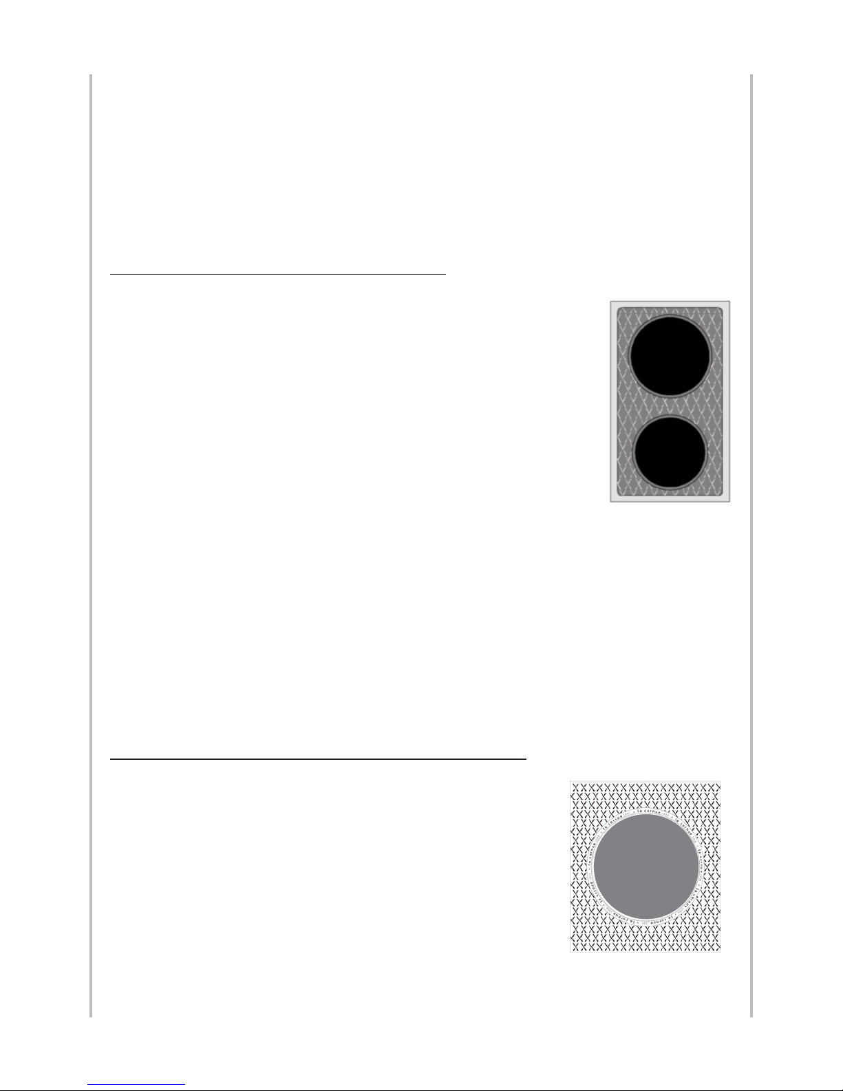
1.4.1 Induction plates with 2 cooking zones
The 145 mm or 180 mm cooking zone adapts itself and automatically
recognizes the diameter of the pan used (120 - 250 mm) and therefore
evenly distributes the heat in the pan, thus ensuring that all of the
food is cooked at the same temperature.
Your hob’s heat settings range from 1800 Watts for the small burner
(145 mm diameter) or 2500 Watts for the large burner (180 mm
diameter).
The maximum power for the two burners is 3 700 Watts.
To start the induction hob, turn the knob clockwise to the desired
position - the indicator [1] to [9] appears. To increase the power, turn
the knob clockwise and to decrease, turn the knob anti-clockwise.
To switch off your cooking area, turn the knob back to the vertical position by turning anticlockwise. The symbol [0] or [H] appears on the display.
For more information relating to induction hob, refer to «Instructions for use Induction
Hob La Cornue», supplied with your cooker.
As long as the symbol [H] of residual heat is on, do not touch the cooking zones
and do not place anything sensitive to heat on the ceramic glass.
Risk of burns and fire.
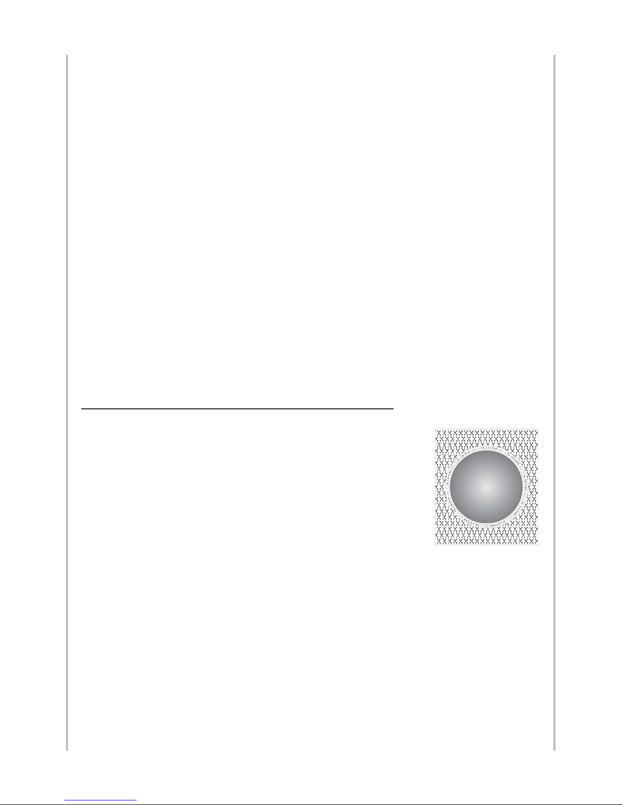
1.4.2. Large induction plate (Grand-Papa 135 and 180)
The large cooking surface with a diameter of 280 mm is suited
for large recipients with a minimum diameter of 180 mm
to 300 mm, so as to provide the best heat distribution to the
recipient, thereby achieving even cooking.
Your cooker has a nominal heating power of 2400 Watts, and
with the ultra-powered “booster” function, it can reach 3700
Watts.
The ultra-powered function works together with the cooker’s
power. It is a very useful function. For example, it can bring a
large pan of water to a boil quickly.
Page 33
33
IGNITION – ADJUSTMENTS Induction plates
To turn on the large cooking surface, simply turn the heat selector clockwise to positions
1-6. To turn off the cooking surface, turn the dial to position 0. The indicator light will turn
off.
To use the “booster” function, it is necessary to first find the maximum position. An
additional clockwise turn will start this function. The heat selector will then return itself
to the maximum heating position without stopping the “booster” mode.
There are 4 ways to stop the “booster” function:
- Turn it the same way as you did to start the function.
- Reduce the heating power by turning the selector anti-clockwise.
- Remove and put the cookware back (pan, saucepan, etc).
- Wait for the function to stop automatically. For safety reasons, the system automatically
switches off the “booster” function after 10 minutes.
The indicator light gives 4 types of notification:
1. Normal operation: steady light
2. No cookware: slow blinking
3. “Booster” mode: blinking with a long lit period followed by a short unlit period
4. Induction generator fault: very fast blinking
When the temperature in the heating area is greater than 60°C, an “H” symbol appears on
the surface when the cooker is off; this symbol disappears when the temperature in the
heating area drops below 60°C.
1.4.3. Grand WOK induction (Grand-Papa 135 and 180)
The Wok induction cooker is made of ceramic glass, a material that
cannot be deformed when heated and is easy to clean with the
simple wipe of a sponge.
The principle of induction cooking is based on the creation of a
magnetic field between the recipients and the inductors. The
ceramic glass surface is electrically and magnetically passive and
heated only by the heat given off by the cookware.
An identical phenomenon happens for the induction Wok where
the inductors match up with the curved shape of the Wok cooking
surface. Only the Wok and the ingredients are heated, the Wok support itself remains at
room temperature. The cooking surface remains cool around the recipient, allowing it to
be cleaned easily because spillage will not burn on.
The magnetic field reacts immediately to the change in selected temperature and allows
the cooking surfaces to adjust quickly.
The large cooking surface of our Grand WOK induction with a cooking surface of 300
mm in diameter is specially suited for cooking in pans with round bottoms.
Your cooker has a nominal heating power of 2300 Watts, and with the ultra-powered
“booster” function, it can reach 3000 Watts.
The ultra-powered function provides additional power to the cooker.
Notice d’installation ligne “Cornuchef” Centenaire - GB
08NOTINSTGSC100/GB-4
Page 34
34
Induction plates IGNITION – ADJUSTMENTS
To turn on the Grand WOK, simply turn the dial clockwise to positions 1-6. To turn off
your WOK, turn the dial to position 0. The indicator light will turn off.
To use the “booster” function, it is necessary to first find the maximum position. An
additional clockwise turn will start this function. The heat selector will then return itself
to the maximum heating position without stopping the “booster” mode.
There are 3 ways to stop the “booster” function:
- Turn it the same way as you did to start the function.
- Reduce the heating power by turning the selector anti-clockwise.
- Wait for the function to stop automatically. For safety reasons, the system automatically
switches off the “booster” function after 10 minutes.
The indicator light gives 4 types of notification:
1. Normal operation: steady light
2. No pan or saucepan: slow blinking
3. “Booster” mode: blinking with a long lit period and a short unlit period.
4. Induction generator fault: very fast blinking
When the temperature in the heating area is greater than 60°C, an “H” symbol appears on
the surface when the cooker is off; this symbol disappears when the temperature in the
heating area drops below 60°C.
1.5. Electric hotplate
To heat the electric hotplate, turn the control knob towards the right
or towards the left to the desired position:
- MAX, corresponds to the highest power,
- 0, corresponds to the shutoff position.
1.6. Electric Teppan-Yaki (Japanese grill)
- Small model: 284 x 478 mm, power: 1 600 W
- Large model: 419 x 478 mm, power: 2 200 W
The electric Teppan-Yaki is equipped with thermostat-controlled
heating elements; the control knob allows you to adjust the
temperature from 50°C (position 1) to 250°C (position 6).
Turn the thermostat knob to the desired temperature; the green light
indicates that the appliance is heating.
The green indicator light is turned off when the desired temperature
is reached; you can then add the food that you want to grill.
After use, return the thermostat knob to the position “0” (shutoff)
Position 1 of the knob correspond to 50°C, Position 2 to 90°C, Position 3 to
130°C, Position 4 to 170°C, position 5 to 210°C and position 6 to 250°C. Those
temperatures are given as an indication, and are relating to the center of the
grill.
The grilling surface is warmer in the middle than along the edges. Use the edges to keep
food warm or to heat it through.
Notice d’installation ligne “Cornuchef” Centenaire - GB
08NOTINSTGSC100/GB-4
0
3
1
2
4
5
6
Page 35

IGNITION – ADJUSTMENTS
35
Notice d’installation ligne “Cornuchef” Centenaire - GB
08NOTINSTGSC100/GB-4
2.1. Gas oven with electronic ignition
The simmerstat C switches on the heating element on the vault of the
oven (grill), the thermostat B switches on the gas ramp.
The simmerstat and the thermostat are both equipped with indicator
lights.
Oven ignition:
Turn the oven thermostat (B) to the desired temperature.
The electronic temperature regulation system allows you to control the
temperature entirely automatically; it is therefore entirely normal that
the flames ignites itself and turns itself off to keep the oven at the desired
temperature
Note:
The red indicator in the bottom part of the control box indicates any
operational defects related to oven ignition. If this indicator is ON, check
that the gas shutoff valve is set to the open position and the cooker is well
supplied with gas, then press the button (G) above the indicator light.
Before using the oven for the first time or if it has not been used for a long period of time,
you have to press this button several times to defuse any trapped air from the gas circuit.
If this phenomenon persists, contact our after-sales department or your dealer.
2.2. Electric oven
The simmerstat C activates the heating element in the vault of the oven
(grill); the thermostat B activates the heating element under the oven
floor. The simmerstat and the thermostat are both equipped with an
indicator light.
Oven ignition:
- Position the selector switch (D) on the “oven floor” position (on the left).
- Then turn the oven thermostat (B) to the desired temperature and the
simmerstat (C) to the corresponding preheating power.
- After preheating (between 15 and 20 minutes depending on the
temperature required), set the cooking mode for the food to be cooked.
- You can then place your food in the oven.
2.3. Grill Function (gas and electric ovens)
Your oven is equipped with an electric grill controlled separately from the heating element
on the oven floor.
- Position the simmerstat (C) on the desired power setting.
- After preheating (between 5 and 10 minutes depending on the temperature), set the
cooking mode for the food to be cooked.
Starting with the ovens
2. STARTING WITH THE OVENS
C
B
G
boulangère
sole
C
B
D
Page 36

36
Notice d’installation ligne “Cornuchef” Centenaire - GB
08NOTINSTGSC100/GB-4
IGNITION – ADJUSTMENTSStarting with the ovens
- You can then place in the grill the food that requires grilling.
When using the “grill” function, you should leave the oven door ajar and pull the
hob drip tray towards the front as far as the (F) mark.
In this position, the oven light is on to allow you to keep an eye on the food cooking.
2.4. Baking stone function (option for electric ovens)
The “baking stone” option
consists of:
a refractory stone, a 3 000 W
electric heating element and
a stainless steel bread spatula.
To start using your “baking
stone”, you must follow
these instructions:
- Remove the cover from the
baking stone heating element
plug (at the back of the
oven).
- Attach the heating element
by inserting it into the
corresponding plug.
- Place the “shelf” grill in the
centre of the oven (2nd level) and then place the baking stone on the grill.
- Turn the selector switch (D) to the “baking stone” position (on the right) and the
thermostat (B) to the desired temperature.
- After preheating (between 10 and 15 minutes depending on the desired temperature),
you can then place your food to cook in the oven.
The baking stone can also be preheated by setting the selector switch (D) to the “oven floor” position
(on the left) and the thermostat (B) to about 220°C. After preheating (between 15 and 20 minutes),
turn the selector switch to the “baking stone” position on the right and place the food to cook in the
oven.
After cooking on the baking stone, leave it in the oven to cool down. Then, remove the
stone and the heating element from the oven, and replace the plug cover on the plug at
the back of the oven.
The light is located on the side at the top of the oven; it is automatically switched on when
the oven door is opened.
Please note: disconnect your oven before interfering with the light to prevent any risk of
an electrical shock and to allow the appliance to cool down (if necessary).
Remove the protection glass and then unscrew the damaged light.
3. REPLACING THE OVEN LIGHT
cover
plug
stone
heating
element
Grill on the
2nd level
Page 37

IGNITION – ADJUSTMENTS
37
Notice d’installation ligne “Cornuchef” Centenaire - GB
08NOTINSTGSC100/GB-4
Changing the injectors
Refit a new light and the protection glass.
Technical characteristics of the light:
- 25 W - 230 - 240 V
- 300°C - E14 base
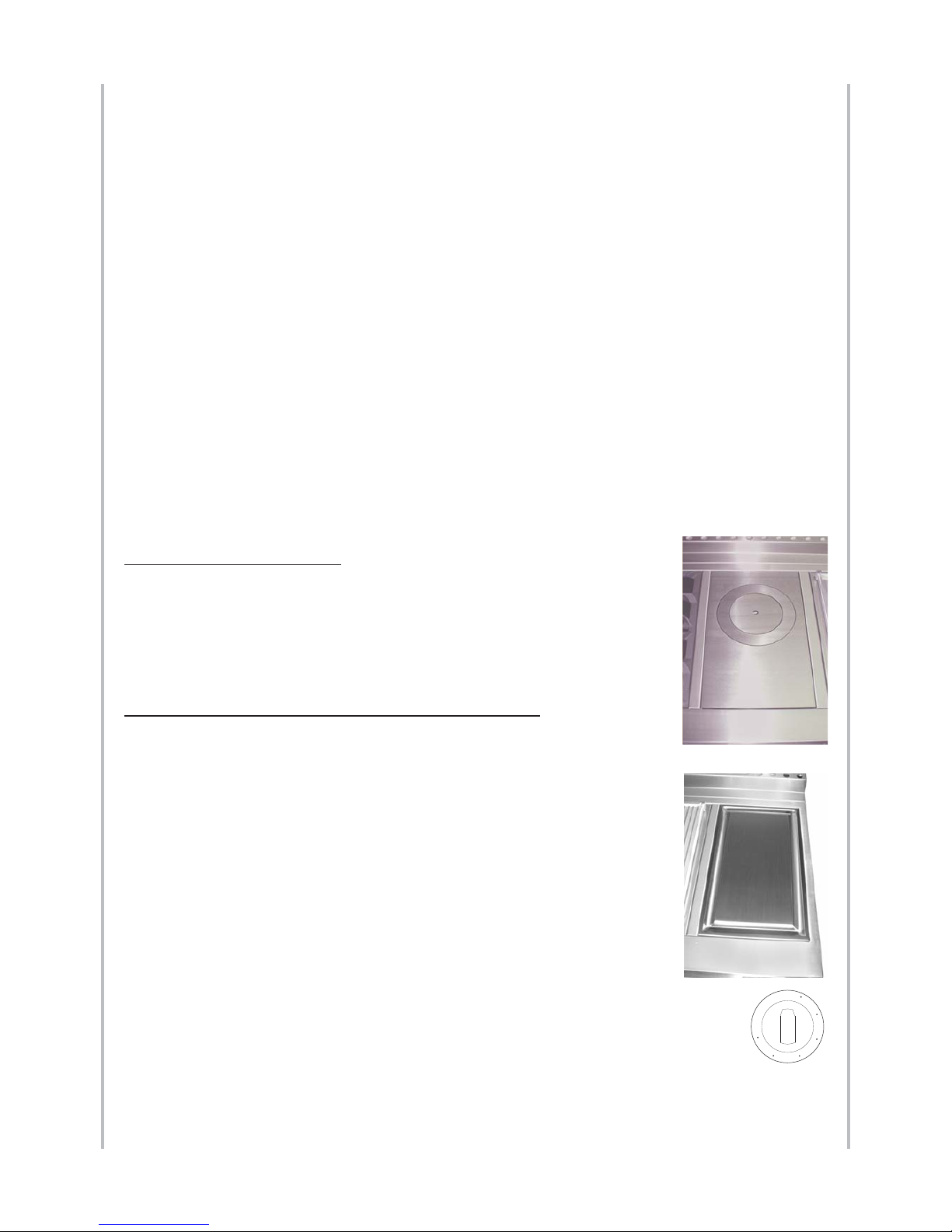
The part numbers of the injectors for the various burners and the gas oven (see their
locations on the photographs below) differ depending on the type of gas used and the
country of installation.
GAS BURNER AND HOTPLATE
The replacement of the burner and cast iron solid top injectors has to be done as follow:
u- Remove the pan support or the solid top.
v- Remove the burner cap.
w- Unscrew the injector with 7 mm standard wrench. Place the new injector and
screw it.
x- Replace the burner capon the burner.
y- Replace the pan support or the solid top.
Injector for gas oven
4. CHANGING THE INJECTORS
Injector
Burner cap
Injector
1
2
3
Page 38

38
Notice d’installation ligne “Cornuchef” Centenaire - GB
08NOTINSTGSC100/GB-4
IGNITION – ADJUSTMENTSAdjusting the low settings
The gas oven injectors are always replaced in the following sequence:
u- Screw the adjusting cone (2) and insert it into the mixing tube in order to free
sufficient space for unscrewing the injector.
v- Unscrew the injector (1) with a 7 mm flat wrench.
w- Install the injector (1) corresponding to the new type of gas and tighten it.
x- Ignite the burner and adjust the air inlet (see the table opposite for the primary air
adjustment) by screwing or unscrewing the adjusting cone (2) until you obtain a
slightly blue flame showing no separation; separation of the flame is an indication
that there is too much air.
y- Then block the adjusting cone (2) with the blocking washer (3).
Once you have changed the injectors, it is a good idea to adjust the low settings for the
hob burners (see Section 5).
Only the low settings for the gas hob burners, the hotplate, the snack griddle and the lava
rock grill can be adjusted with the following procedure:
u- Ignite the burner to be adjusted, and then turn the
control knob to the “low” position.
v- Dismantle the control knobs by unscrewing from each
knob the screw holding it in place.
w- Turn the split screw on the body of the gas tap towards
the left to increase the flow or towards the right to reduce
it.
For Butane and Propane gas, turn the knob fully to the
right.
Make sure that the resulting flame, at the lowest setting, is sufficiently strong to heat
the thermocouple.
x- Refit the knob to turn the burner off, ensuring that you leave a sufficient gap
between the knobs and the tap cover (the knob, when held down, should not come
into contact with the tap cover).
Once the appliance has been adapted to a different type of gas or to a pressure
other than those for which it was previously set, the new settings will have to be
indicated in place of the previous settings, and a new gas information label will
be supplied with the new injectors.
Any sealing will have to be replaced.
5. ADJUSTING THE LOW SETTINGS
A
Page 39
IGNITION – ADJUSTMENTS
39
Notice d’installation ligne “Cornuchef” Centenaire - GB
08NOTINSTGSC100/GB-4
Injectors table
All the adjustments and replacement of injectors or bypass screws must be
carried out by a qualified professional.
The part numbers of the injectors for the various hot top burners (see locations on the
diagram page 33) differ, depending on the type of gas and country of installation.
The following table defines which injector and bypass screw should be used if the type of
gas is changed or if you move.
Injectors table:
Country:
CAUTION : the BY-PASS screws are adjusted for natural gas G20 - 20 mbar and G25 - 20 / 25 mbar
For BUTANE / PROPANE gas G30 / G31 - 28 / 30 / 37 mbar - Screw the by-pass to the maximum
For BUTANE / PROPANE gas G30 / G31 - 50 mbar - Change the by-pass screws and screw to the maximum
6. INJECTORS TABLE
AT : Austria
BE : Belgium
CH : Switzerland
CY : Cyprus
CZ : Czech Republic
DE : Germany
DK : Denmark
EE : Estonia
ES : Spain
FI : Finland
FR : France
GB : United Kingdom
GR : Greece
HR : Croatia
HU : Hungary
IE : Ireland
IT : Italy
LT : Lithuania
LU : Luxembourg
LV : Latvia
NL : Netherland
NO : Norway
PL : Poland
PT : Portugal
RO : Romania
SE : Sweden
SI : Slovenia
SK : Slovakia
TR : Turkey
Page 40
40
Notice d’installation ligne “Cornuchef” Centenaire - GB
08NOTINSTGSC100/GB-4
EUROPEAN DIRECTIVES EUROPEAN DIRECTIVES
All of our appliances comply with the following European Directives:
- Directive 2009 / 142 / EC "GAS APPLIANCES”, European Standard EN 30
- Directive 2006 / 95 / EC "LOW VOLTAGE"
- Directive 2004 / 108 / EC "ELECTROMAGNETIC COMPATIBILITY"
- Directive 2002 / 40 / EC "ENERGY LABELLING"
- Directive 2002 / 96/ EC "WEEE, WASTE FROM ELECTRICAL AND ELECTRONIC
EQUIPMENT"
- Directive 2002 / 95 / EC "RoHS, RESTRICTIONS OF HAZARDOUS SUBSTANCES"
The European Parliament’s 2002/96/EC Directive on waste from electrical and electronic
equipment (WEEE) requires that used household appliances are not disposed of in unsorted municipal landfills and must be collected separately to optimise recovery and recycling
of the materials they contain and thus reduce their impact on human health and the environment. Consumers should contact their local authorities or their dealer with regard to
the procedure to be followed for the collection of their old appliance. Please comply with
local regulations for disposal of the packaging material. The packaging can thus be recycled.
This “crossed-out bin” logo found on all products means that the equipment cannot be disposed of with other waste, that it is the object of a
selective collection with a view to recovery, reuse or recycling.
ENERGY CONSUMPTION
WASTE FROM ELECTRICAL AND ELECTRONIC EQUIPMENT
COMPLIANCE WITH EUROPEAN DIRECTIVES
ELECTRIC OVEN Large Vaulted Oven
Ratings
6 kW
(3,5 kW floor + 2,5 kW vault)
Energy efficiency class
on a scale of A (more efficient) to G (less efficient)
G
Energy consumption based on standard load 2,14 kWh
Usable volume (litres) 74
Size Large
Time to cook standard load (minutes) 69
Baking area
2796 cm
2
Page 41

41
WARRANTY WARRANTY
Notice d’installation ligne “Cornuchef” Centenaire - GB
08NOTINSTGSC100/GB-4
Following receipt of full payment for our
goods, our appliances are guaranteed three
years from the invoice date against any
structural faults and any material defects. The
warranty excludes improper use of the
appliance or a non-compliant installation.
Intervention and travel costs will be billed in
this event.
If our goods were to dysfunction, the buyer
then has to contact us once he has ensured
that it is not due to a non-compliant
installation or abnormal use in order to decide
with us how the appliance should be
repaired. The appliance should be cleaned
and clean prior to any intervention.
Any complaints with regard to the state, the
presentation or the non-compliance of our
goods should be addressed to our
headquarters by recommended letter with
acknowledgement of receipt within a
maximum of eight days following delivery.
The application of the warranty will be
subject to LA CORNUE SAS receiving a
certificate stating that the material has been
installed by a professional in accordance with
the current technical and safety standards.
Under this warranty, the seller shall replace at
no cost the parts recognized as faulty by its
technical department. This warranty covers all
labour costs with the exception of travel
expenses.
The warranty period specified above shall not
be extended if faulty parts need to be
replaced.
WE TAKE GREAT CARE IN THE CREATION
OF OUR ENAMELLED ITEMS. However, a
hand-crafted enamel surface is never
completely even and slight variations in shade
may occur. This is a guarantee of quality and
is linked to the nature of our three-layer
enamelling process.
This warranty shall cease to apply:
l If the operational defect is the result of an
unauthorized intervention on the appliance;
l If the faulty operation is due to normal
wear and tear of the appliance or from
negligence or insufficient maintenance by the
buyer;
l If the faulty operation is due to force
majeure.
LA CORNUE SAS shall not be held legally
responsible in these three cases.
The seller’s guarantee and his responsibility
for products shall be limited to repairs to any
defects as stipulated in the above conditions.
As expressly agreed between the contracting
parties, the seller’s responsibility in the event
of an operational fault shall be limited to the
above provisions, especially with regard to
concealed defects as well as material and
immaterial damage.
In all cases, the buyer may not suspend
payment if he lodges a complaint about
the quality of the goods.
The goods are always transported at the
buyer’s or his representative’s own risks. It is
therefore their responsibility to check them
upon arrival and, if necessary, to lodge a
complaint with the haulier. After having
expressed specific established reservations on
the delivery slip upon receipt, the buyer must
confirm them by recommended letter to the
haulier within two days of receipt (Article 105
of the Commercial Code).
We cannot in any event honour this warranty
if these requirements are not met.
WARRANTY (3 YEARS)
After-Sales Department:
- Covered by the warranty:
tel: +33 (0)1 34 48 36 15 fax: +33 (0)1 34 48 52 31
- Not covered by the warranty (appliance older than three years):
tel: +33 (0)1 47 37 56 00 fax: +33 (0)1 47 39 10 49
Page 42

42
Notice d’installation ligne “Cornuchef” Centenaire - GB
08NOTINSTGSC100/GB-4
HEADQUARTERS AND WORKSHOP
14, rue du Bois du Pont - Z.I. Les Béthunes
95310 SAINT OUEN L’AUMONE
POSTAL ADDRESS:
BP 99006 - 95070 Cergy Pontoise Cedex
FRANCE
Tel: +33 (0)1 34 48 36 36
Fax: +33 (0)1 34 64 32 65
www.la-cornue.com
e-mail: a.table@la-cornue.com
 Loading...