

La Cornue Grand-Papa 135, GM2-EE 123, GM2-GE 120, GM2-EE 173, GM2-EE 120 Installation Manual
...Page 1

1
Dear Customer,
Thank you for purchasing a La Cornue cooker. We hope that you will really enjoy
preparing delicious meals with it.
The aim of this installation guide is to familiarise you with the potential of a
professional quality appliance designed for domestic use and to facilitate its upkeep.
Above all, a La Cornue cooker is manufactured from noble and pure materials. The
specific choices for certain components, such as brass for the burners and cast-iron for
the hotplate, correspond to technicality and professional performance requirements
which are not attainable with other materials or protective treatments. We are very
much attached to the authenticity of our cookers and we are convinced that you will
appreciate them even more as you use them.
We recommend you follow the advice provided in the “Instructions for Use” brochure;
this will ensure that you are satisfied with your cooker for a long time.
Thank you for placing your trust in us.
Xavier Dupuy
President and Managing Director
Page 2

2
©2007 - LA CORNUE – Installation Guide for Europe - “Cornuchef” Range.
Novemeber 2007 - A.K.
Page 3

3
Installation Guide - “Cornuchef” Range
WARNING
T
his appliance must be installed by a qualified professional in accordance with the
current regulations in the country where the appliance is installed and must only be
used in a well ventilated area. Read the guides before installing and using this
appliance.
Appliance categories (see pt. 1.2, page 14 “Installation”):
- Class 1: Free-standing cooking appliance not normally in direct contact with the kitchen
units or the surrounding walls.
-Class 2: Cooking appliance that can be integrated between two kitchen units, whose walls
can be in direct contact with the surrounding units. This type of appliance can be in
contact with only one kitchen unit during installation.
- Class 2 / Sub-Class 1: Class 2 appliance that can be free-standing or installed so that the
side panels are accessible.
Before installing the appliance, ensure that the local gas supply conditions (gas type and
pressure) and the adjustment of the appliance are compatible.
The adjustment conditions for this appliance are indicated on the label at the back of the
hob and on the test certificate.
This appliance is not intended to be connected to a ventilation system or a ventilation shaft
for combustion products. It should be installed and connected in accordance with the
current regulations, and special attention should be paid to the applicable ventilation
regulations.
The use of a gas cooking appliance results in the production of heat and moisture in the
room where it is installed. Ensure that the room is well ventilated: keep natural ventilation
holes open or install a mechanical ventilation device (mechanical extractor hood).
Prolonged or intensive use of the appliance may call for additional ventilation, e.g. by
opening a window, or for more effective ventilation, by increasing the power of the
mechanical ventilation system installed.
The parts that are protected by the manufacturer must not be manipulated by the installer
or the user.
Please note:
The accessible parts may be hot when the oven is being used: keep young children at a safe
distance.
All of our cooking appliance belong to Class 1 and Class 2 / Sub-Class 1 and are designed for domestic use
only. They meet the requirements of the 90/396/CEE European Directive (“Gas Appliances”) and the
72/73/CEE European Directive (“Low Voltage Directive”), both amended by the 93/68/CEE Directive.
Page 4

4
Installation Guide - “Cornuchef” Range
WARNING ..................................................................................................... 3
DESCRIPTION ............................................................................................... 5
1. General description ................................................................................... 5
2. Hob configurations .................................................................................... 6
3. Energy power and gas flow rates .............................................................. 7
4. Power ratings for the electrical elements ............................................... 7
COOKER “GRAND - MAMAN 90” ................................................................. 8
1. Dimensions ................................................................................................. 8
2. Connections ................................................................................................ 8
3. Energy power ............................................................................................. 9
COOKER “GRAND - PAPA 135” .................................................................... 10
1. Dimensions ................................................................................................10
2. Connections .............................................................................................. 10
3. Energy power ............................................................................................ 11
HOBS ............................................................................................................ 12
1. Dimensions hob “Grand-Maman 90” ....................................................... 12
2. Connections hob “Grand-Maman 90” ....................................................... 12
3. Dimensions hob “Grand-Papa 135” .......................................................... 12
4. Connections hob “Grand-Papa 135” ......................................................... 13
5. Energy power hobs “Grand-Maman 90” and “Grand-Papa 135” .............13
BEFORE DELIVERY ..................................................................................... 14
1. Safety requirements ................................................................................. 14
2. Electrical supply ....................................................................................... 15
3. Gas supply ................................................................................................ 16
4. Installation ............................................................................................... 16
CONNECTIONS ............................................................................................ 17
1. Electrical connections .............................................................................. 17
2. Gas connection ........................................................................................ 18
IGNITION - ADJUSTMENTS ........................................................................ 19
1. Starting the appliance .............................................................................. 19
2. Replacing the oven light .......................................................................... 23
3. Changing the injectors ............................................................................. 24
4. Adjusting the low settings ........................................................................25
5. Injectors table ........................................................................................... 26
WARRANTY ................................................................................................. 27
CONTENTS
Page 5

5
Installation Guide - “Cornuchef” Range
DESCRIPTION General description
DESCRIPTION
1. GENERAL DESCRIPTION
The range of "CORNUCHEF" cooking appliances consists of 4 models:
- Cooker “Grand-Maman 90” (model GM2, width: 90cm).
- Cooker “Grand-Papa 135” (model GP2, width: 135cm).
- Hob “Grand-Maman 90” (model TM2, width: 90cm).
- Hob “Grand-Papa 135” (model TP2, width: 135cm).
Each of the cooker or hot top models includes several sub-models, depending on the chosen hot top and its combination with the oven.
The cookers in the "CORNUCHEF" range consist of:
- a thermostatically-controlled electric or gas oven;
- one hot top bounded at the rear by a stainless steel skirting creating a gap between the
cooker and the wall, thus ensuring the removal of burnt gases and smells.
The "Grand-Papa" stove is equipped with a 45 cm wide electric steam oven, located to the
right of the oven, which is used to warm plates.
Page 6

DESCRIPTION
6
Installation Guide - “Cornuchef” Range
Hob configurations
2. HOB CONFIGURATIONS
2 gas burners (small burner at the rear)
1 single gas burner
2 gas burners
2 gas burners (small burner at the rear)
1 gas hotplate
2 gas burners
2 gas burners (small burner at the rear)
1 single gas burner
2 electric ceramic plates
2 gas burners (small burner at the rear)
1 single gas burner
2 electric induction plates
2 gas burners (small burner at the rear)
1 gas hotplate
2 electric ceramic plates
2 gas burners (small burner at the rear)
1 gas hotplate
2 electric induction plates
2 electric ceramic plates
1 electric hotplate
2 electric ceramic plates
2 electric induction plates
1 electric hotplate
2 electric induction plates
123
124
2 gas burners (small burner at the rear)
1 single gas burner
1 small electric teppan-yaki
120
174
129
173
179
989
484
ALL GAS
MIXED (GAS AND ELECTRIC)
ALL ELECTRIC
2 electric ceramic plates
1 small electric teppan-yaki
2 electric ceramic plates
2 electric induction plates
1 small electric teppan-yaki
2 electric induction plates
909
404
ALL ELECTRIC WITH TEPPAN-YAKI
Page 7
7
Installation Guide - “Cornuchef” Range
DESCRIPTION Energy power
All of our appliances belong to Category II and are designed for gases from the second and
third groups.
The gas used can be either natural gas, propane or butane, depending on availability. Refer
to pages 24 – 26 for information about adapting your cooker or your hob to the various
types of gas.
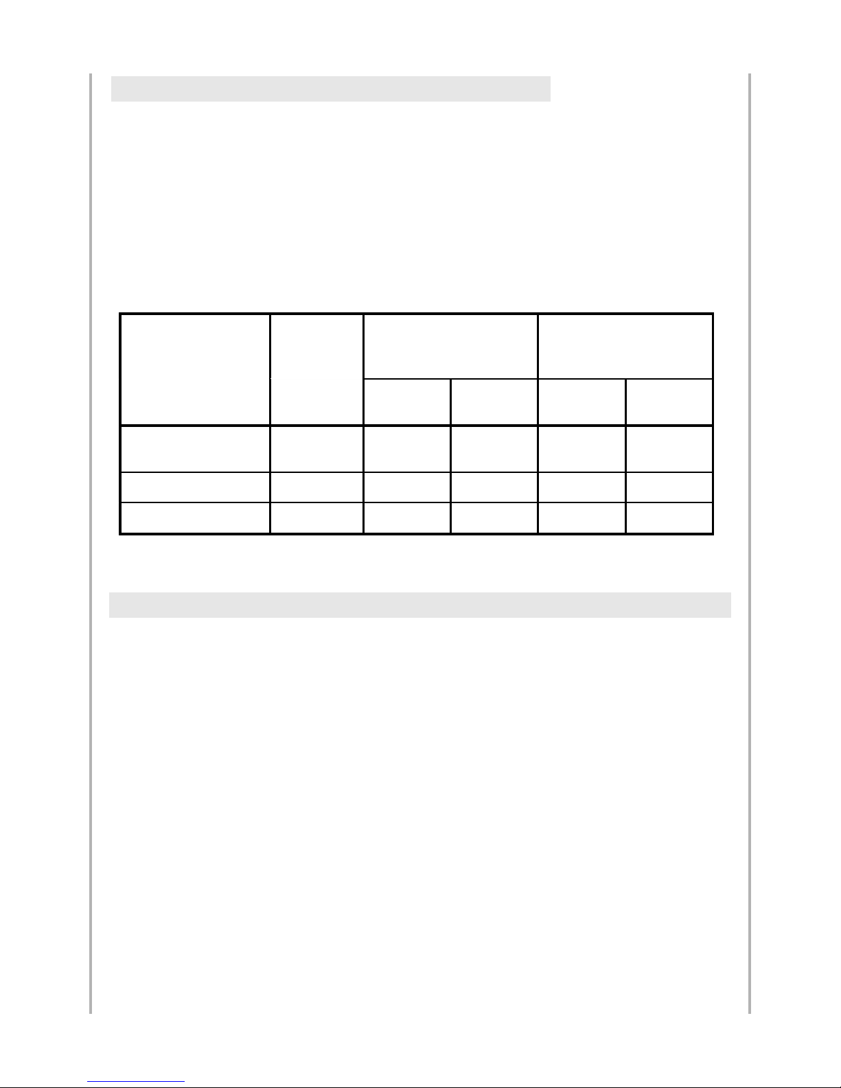
The tables below summarise for each gas type and for each burner the heat flow rate
(energy power in kW, Maximum Heat Power) and the volume flow rate (in m3/hour) or
the mass flow rate (in kg/hour) of useful gas.
Large vaulted electric oven (74/84 litres, large volume) ......................................... 6 000 W
3 500 W oven floor + 2 500 W vault
Grill in large vaulted gas oven ..............................................................................… 2 500 W
Baking stone ............................................................................................................ 3 000 W
Oven light ..................................................................................................................... 25 W
Ignition for small and large vaulted gas ovens .............................................................. 25 W
Automatic ignition for gas burners ............................................................................... 25 W
Warming cupboard, width: 450 mm ....................................................................… 1 750 W
Electric ceramic hob, Ø 145 mm .............................................................................. 1 200 W
Electric ceramic hob, Ø 195 mm (2 zones) .............................................................. 1 800 W
Round electric plate, Ø 180 mm .............................................................................. 2 000 W
Round electric plate, Ø 220 mm .............................................................................. 2 000 W
Electric hotplate ..........……………………………..................................................... 1 300 W
(small, dimensions: 284 x 476 mm)
Small “La Cornue” Teppan-Yaki .................................................….......................... 1 600 W
Induction plates (2 burners) ................................................................................… 3 600 W
3. ENERGY POWER AND GAS FLOW RATES
4. POWER RATINGS FOR THE ELECTRICAL ELEMENTS
Burner
Nominal heat
flow
Volume flow rate (m
3
/ hour)
Mass flow rate (kg / hour)
(Maximum
Heat Power in
kW)
Natural Gas
G20, 20 mbar
Natural Gas
G25 20 mbar
Propane
G31 37 mbar
Butane
G30 29 mbar
Gas hobs:
- large burner
- small burner
3
1,7
0,29
0,16
0,33
0,19
0,21
0,12
0,22
0,12
Hotplate
3
0,29
0,33
0,21
0,22
Large vaulted gas oven
(74/84 l)
6,5
0,62
0,72
0,46
0,47
Page 8

8
Installation Guide - “Cornuchef” Range
Dimensions, connections GRAND-MAMAN 90
Mixed gas/electric cooker
All-electric cooker
2. COOKER CONNECTIONS
GRAND - MAMAN 90
220 480 200
900
950
80
575
40
50
900
40
50
650
140
140
200
200
100
100
125
125
140
140
Rear view
200
200
Rear view
CABLE 2
CABLE 1
CABLE 1
1. C
OOKER DIMENSIONS
TERMINAL
BLOCK 1
TERMINAL
BLOCK 2
CABLE 2 & 3
TERMINAL
BLOCK 1
TERMINAL
BLOCK 2 & 3
GAS INLET
MALE G 1/2 CONNECTION
GAS INLET
MALE G 1/2 CONNECTION
Cooker weight: 110 - 150 kg. depending on the model
Page 9

9
Installation Guide - “Cornuchef” Range
GRAND-MAMAN 90 Gas and electric Power
GRAND - MAMAN 90
3. POWER FOR GAS AND ELECTRIC COOKERS
Page 10

10
Installation Guide - “Cornuchef” Range
Dimensions, connections GRAND-PAPA 135
Mixed gas/electric cooker
All-electric cooker
2. COOKER CONNECTIONS
GRAND - PAPA 135
1350
480
200
220
Cooker weight: 180 - 220 kg. depending on the model
950
80
575
40
50
900
40
50
650
140
140
200
200
100
100
125
125
140
140
Rear view
200
200
Rear view
CABLE 2
CABLE 1
CABLE 1
GAS INLET
MALE G 1/2
CONNECTION
1. C
OOKER DIMENSIONS
TERMINAL
BLOCK 1
TERMINAL
BLOCK 2
CABLE 2 & 3
TERMINAL
BLOCK 1
TERMINAL
BLOCK 2 & 3
GAS INLET
MALE G 1/2 CONNECTION
Page 11

11
Installation Guide - “Cornuchef” Range
GRAND-PAPA 135 Gas and electric Power
GRAND - PAPA 135
3. POWER FOR GAS AND ELECTRIC COOKERS
* PLEASE NOTE: For 2 cables and a 400 V a.c. 3N power supply (3 Ph + N + T)
- 1 cable is 400 V a.c., 3-PHASE
- 1 cable is 230 V a.c., SINGLE-PHASE
Page 12

12
Installation Guide - “Cornuchef” Range
Dimensions, connections HOBS 90 & 135
Mixed gas/electric hob
All-electric hob
2. HOB
“GRAND
-MAMAN 90” CONNECTIONS
HOBS 90 & 135
250
200
40
650
50
Rear view
Rear view
CABLE 2
CABLE 1
CABLE 1
GAS INLET
MALE G 1/2 CONNEC-
TION
1. H
OB “GRAND
-MAMAN 90” DIMENSIONS
TERMINAL
BLOCK 1
TERMINAL
BLOCK 2
TERMINAL
BLOCK 1
GAS INLET
MALE G 1/2 CONNECTION
200
900
Hob weight: 70 - 90kg. depending on the model
250
200
40
650
50
3. HOB “GRAND-PAPA 135” DIMENSIONS
1350
200
Hob weight: 80 - 100kg. depending on the model
Page 13

Mixed gas/electric hob
All-electric hob
13
Installation Guide - “Cornuchef” Range
HOBS 90 & 135
HOBS 90 & 135
TT--22----00EE 112233 1133,,77 11,,3322 11,,5511 00,,9966 11 2255 11
0,1 0,5 _ _ _
TT--22----00EE 117733 1133,,77 11,,3322 11,,5511 00,,9966 11 2255 11
0,1 0,5 _ _ _
TT--22----00EE 112200 77,,77 00,,7744 00,,8855 00,,5544 00,,5566 11662255 11
71___
TT--22----00EE 112244 77,,77 00,,7744 00,,8855 00,,5544 00,,5566 33002255 11
13,5 1,5 _ _ _
TT--22----00EE 112299 77,,77 00,,7744 00,,8855 00,,5544 00,,5566 33662255 11
16 1,5 _ _ _
TT--22----00EE 117744 77,,77 00,,7744 00,,8855 00,,5544 00,,5566 33002255 11
13,5 1,5 _ _ _
TT--22----00EE 117799 77,,77 00,,7744 00,,8855 00,,5544 00,,5566 33662255 11
16 1,5 _ _ _
TT--22----00EE 448844 00 00 00 00 00 77330000 11
32 4 1 13 1,5
TT--22----00EE 998899 00 00 00 00 00 88550000 22
21,5 2,5 / 1,5 1 16 1,5
TT--22----00EE 440044 00 00 00 00 00 77660000 22
20 2,5 / 1,5 1 13 1,5
TT--22----00EE 990099 00 00 00 00 00 88880000 22
23 2,5 / 1,5 1 16 1,5
Propane Gas
G31 - 37
mbar
GGAASS SSUUPPPPLLYY
IINNFFOORRMMAATTIIOONN
Butane Gas
G30 - 29
mbar
Mass Flow
Rate
k g/hour
Volume F low
Rate
m3/hour
MMoo ddeell
HHEEAATT FFLL OOWW
kkWW MMHHPP
Natural gas
G20 - 20
mbar
Natural gas
G25 - 20
mbar
Current
(A)
EELLEECCTTRRIICC SSUUPPPPLLYY IINNFFOORRMMAATTIIOONN
Current
(A)
Nominal
cable
section
mm
2
Nominal
cable
section
mm
2
TToottaall ppoowweerr iinn
WWaattttss
Number of
cables
440000 VV aa..cc .. 33NN
ppooww eerr ssuuppppllyy
((33 PPhh ++ NN ++ TT))
Number of
cables
223300 VV aa..cc ..
ppooww eerr ssuuppppllyy
((11 PPhh ++ NN ++ TT))
4. HOB “GRAND-PAPA 135” CONNECTIONS
Rear view
Rear view
CABLE 2
CABLE 1
CABLE 1
GAS INLET
MALE G 1/2 CONNEC-
TION
TERMINAL
BLOCK 1
TERMINAL
BLOCK 2
TERMINAL
BLOCK 1
GAS INLET
MALE G 1/2 CONNECTION
Dimensions, connections
5. P
OWER FOR GAS AND ELECTRIC HOBS
Page 14

14
Installation Guide - “Cornuchef” Range
Safety requirements BEFORE DELIVERY
In order to be able to install your appliance as soon as it is delivered, you will have to check
that the layout of your kitchen and your gas and electricity supplies are ready for it.
1.1. V
entilation
It is essential that the room where the “La Cornue” cooker or hob will be installed has
excellent ventilation, i.e. to the outside for vapour and burnt gases and a fresh air inlet.
Do not use an air recycling system.
A flow rate of at least 4 cubic metres per hour of fresh air per kW of gas heat power is
necessary to ensure the supply of combustion air.
The gas regulations also require high and low ventilation to be installed in the room where
a gas appliance will be installed.
The external ventilation system must consist of fixed aerators or flipping glass panes as
well as vapour aspirators or extractor hoods.
We strongly advise you to use an extractor hood.
Recommended power:
- 700 cubic metres per hour or 10 – 15 times the volume of the air in the room
each hour.
"La Cornue" can propose you models of customized hoods in materials matching your
cooker or extractors that can be integrated into a hood manufactured by the user.
The ventilation hood has to be built with inflammable materials.
For optimum efficiency, the fresh air inlet for renewing the air extracted by the hood must
be located either directly at the back of the appliance or within a 2 – 3m. radius, at ground
level.
1.2. Installation (see following page)
As the oven and the hob are particularly well insulated, the appliance can be built-in
without any need for any special precautions with regard to the surroundings. However,
if the cooker or the hob is installed against a wall, the hottest parts (the strip between 60
and 95cm. from the floor, and the surface between the hob and the extractor hood) must
be protected with a stainless steel plate (credenza) or ceramic tiles.
Ceramic cardboard with a minimum thickness of 20mm. must be installed under
the hob to insulate the units placed underneath.
1. SAFETY REQUIREMENTS
BEFORE DELIVERY
Page 15

15
Installation Guide - “Cornuchef” Range
BEFORE DELIVERY Electrical Supply
MINIMUM DISTANCE FROM THE KITCHEN UNITS (in mm.)
Voltage: 230V a.c., single-phase + neutral + ground
400V a.c. 3N, three-phase + neutral + ground.
Safety:
The electrical supply must necessarily be grounded and must be equipped with a circuit
breaker protection compatible with the appliance’s power rating. In high-risk regions, an
additional protection against natural electrical phenomena (lightning) must be used.
Power:
It is advisable to check whether the power rating of your electrical installation provides
you with sufficient power for your model, taking into account any electrical appliances
you have already installed. Refer to the tables for each of the models for the total power
and current ratings.
Due to the power of La Cornue appliances, a simple plug and socket connection is not
recommended: the electrical connection should consist of a flexible cord without a plug,
directly connected to the circuit breaker outlet by means of a junction box with terminal
blocks, preferably of the anti-shearing type.
Only all-gas hobs with only hob burner ignition can be connected with an ordinary 3-pin
plug.
2. E
LECTRICAL S
UPPLY
300 300
0
0
0
330
450
A
A
minimum 750
recommandé 900
RECOMMENDED 900
MINIMUM 750
Page 16

16
Installation Guide - “Cornuchef” Range
Gas supply BEFORE DELIVERY
The gas installation must comply with the current regulations in the country
where the appliance will be installed.
Reminder of the main obligations with regard to gas installations:
The gas must be supplied via a rigid metallic pipe, terminated by an easily accessible
manual shutoff valve.
This valve must be positioned, taking into account that the gas inlet on the appliance is
situated:
· on the left of the cooker or the hob.
· at the level of the work area (on the bottom left) for hobs.
See the drawings on the specific presentation pages for each model for details about the
connections.
When your cooker or your hob is built-in between two kitchen units, the shut-off valve
must be accessible through an appropriate cut-out in the back of the kitchen unit.
It is forbidden to use flexible rubber hoses with a collar fastening to supply gas to gas
appliances.
When all of the work has been carried out on your gas supply network, perform a
functional test before connecting the appliance; this will ensure that no metallic burrs can
enter the appliance’s gas supply pipe and thus obstruct the burners or the gas taps.
In order to ensure that the hob is perfectly horizontal, especially on old flooring, we advise
you to install your cooker on a wooden or cement base and your hob on a perfectly
horizontal kitchen unit, the height of which will allow you to bring the hob to a level in
accordance with its environment or your own requirements.
Each cooker is equipped with adjustable feet that allow you to compensate for differences
in the floor level.
REMINDER: Ceramic cardboard with a minimum thickness of 20mm. must be
installed under the hob to insulate the units placed underneath.
4. INSTALLATION
3. GAS SUPPLY
Page 17

17
Installation Guide - “Cornuchef” Range
CONNECTIONS Electrical connections
" La Cornue " appliances are supplied with 1 – 3 flexible cords, P/N: H07 RN-F, consisting
of 3 or 5 wires, approximately 1.5m long, ready to be connected to a single-phase or 3phase + neutral power supply, depending on the indications specified on the order form
(see the table corresponding to each model for the power ratings).
All of the electricity supply circuits must be disconnected before accessing the
connection terminal boxes.
REMINDER: the appliance should be connected to the main power supply via terminal
blocks (preferably of the anti-shearing type) and not by means of simple plugs.
Insert the cable below the hot air outlets at the back of the oven, never in front of them.
Should your appliance be connected to a different type of power supply at a later date, in
some cases (please contact our technical department before) it will be possible to change
the cabling accordingly, according to the following instructions:
- Unscrew the protection plate from the back of the appliance in order to access the
connection terminal block(s) to which the various heating elements are connected (if
there are 2 supply cables on the cooker, there are also 2 connection terminal blocks).
230V – single-phase 400V – 3-phase
- For a single-phase 230V power supply, shunt the P1, P2 and P3 terminals, and
then connect the cable wires as follows:
- neutral (blue wire) to N
- the phase (red or brown wire) to P1
- the ground to T (yellow / green)
- For a 3-phase 400V power supply, remove the shunt from the P1, P2 and P3
terminals, and then connect the cable wires as follows:
- neutral (blue wire) to N
- the three other wires (red or brown) to the P1, P2 and P3 terminals.
- the ground to T (yellow / green)
Ensure that the cross-section of the electrical cables corresponds to that
indicated in the tables in the general description for each appliance
1. ELECTRICAL CONNECTIONS
CONNECTIONS
T = Ground
N = Neutral
Ph1 = Phase 1
Ph2 = Phase 2
Ph3 = Phase 3
Page 18

18
Installation Guide - “Cornuchef” Range
Gas connections CONNECTIONS
Our appliances are supplied with injectors corresponding to the type of gas supply specified
in your order (natural gas, butane or propane). These injectors should only be changed if
a different type of gas is used.
See page 26 for the table summarising the injectors to be used for each type of gas, the
country of installation and injector replacement instructions.
If no particular instructions are specified in the order, the appliance is equipped with
injectors for natural gas G20 (pressure: 20 mbar.).
The type of gas for which the appliance is equipped is indicated on a label at the back of
the hob, close to the gas supply pipe and on the test certificate supplied with the appliance.
The cooker or the hob is connected to the gas supply via a male threaded connector with
G ½ thread (previous reference: 15/21).
The previously installed shutoff valve can be connected via a rigid metallic pipe installation
or by means of certified (TFEM) flexible hoses equipped with a mechanical union.
The pipes must be fully accessible and placed so that they cannot be affected by fire or
deteriorated by the combustion gases, the hot parts of the appliances or by hot products
overflowing. They must not be crushed or kinked.
Recommended hose: certified TUBOGAZ for the gas type used.
It is forbidden to connect our gas appliances with flexible hoses mounted on hose
tailpieces.
Refer to the drawings on the description pages for each appliance type for
information about the exact location of the gas and electricity outlets on your
appliance.
If a sealing compound has to be used, we recommend using LOCTITE 542.
For appliances operating with BUTANE / PROPANE gas, use two cylinders with an
automatic reversing switch or an outdoor tank, and a standard pressure reducing valve
adapted to your model’s total flow rate (see tables on pages 9 – 36) and the pressure of the
gas used.
We advise you to use a pressure reducing valve with a minimum of 2 kg/hour for the hobs
and a pressure reducing valve with a minimum of 3kg/hour for the cookers.
As a general rule, an additional safety margin corresponding to 20 – 30% of the appliance’s
maximum flow rate has to be respected.
The pressure reducing valve should be placed more than 2 m. from the appliance to
guarantee constant pressure from the gas supply.
2. GAS CONNECTION
Page 19

19
Installation Guide - “Cornuchef” Range
IGNITION – ADJUSTMENTS Starting the appliance
The gas burners on our “Cornuchef” range appliances are fitted with safety thermocouples:
if a burner shuts off for any reason, the gas supply for that burner is automatically stopped.
1.1. Gas bur
ners with electric ignition
All of our appliances are originally equipped with automatic gas burner
ignition.
To ignite a gas burner, press the control knob and turn it to the left to
the “high flame” position.
The burner is automatically ignited. Keep the knob pressed for 5 – 10
seconds (the safety thermocouple may take longer to react the first
time).
The sparking noise means that the ignition system is operating
normally.
· Low setting: this is achieved by rotating the knob fully to the left or to the bottom.
· Shutoff: bring the knob back to its vertical position by rotating it to the right.
1.2. Hotplate with electric ignition
Ignition identical to that for gas burners.
Gas hotplate
INITIAL IGNITION
Defuse any trapped air from the gas network, starting with each of the burners on
the cooktop. Once this is done, the gas oven can then be ignited. However, if the
safety device for the oven is activated (red indicator ON), press the reset button
above the red indicator to repeat the procedure.
1. STARTING THE APPLIANCE
IGNITION – ADJUSTMENTS
Page 20

20
Installation Guide - “Cornuchef” Range
Starting the appliance IGNITION – ADJUSTMENTS
1.3. Round ceramic plates
To heat a ceramic plate with a single burner (diameter: 145
mm.), turn the knob towards the right or towards the left to
the desired position:
- 1 corresponds to the lowest position,
- 6 corresponds to the highest position,
- 0 corresponds to the shutoff position.
To heat the central burner of a ceramic plate with a double
burner and 2 zones (diameter: 195 mm.), you just have to
rotate the double-circuit simmerstat clockwise.
To ignite the 2 (outer and central) burners, turn the knob towards the right to the sign oo
(see the figure shown opposite) until you hear a click from the microswitch that will light
the peripheral element.
The two burners reach the maximum temperature in this position. You can then set the
temperature of the double burner by turning the control knob to any position between 6
and 1.
Note: it is impossible to only ignite the outer burner.
Please note: if the surface is cracked/fractured, immediately disconnect the appliance or the relevant
part of the supply.
1.4. Induction plates
The 180 mm or 210 mm cooking zone adapts itself and
automatically recognizes the diameter of the pan used (120
- 250 mm) and therefore evenly distributes the heat in the
pan, thus ensuring that all of the food is cooked at the same
temperature.
Your hob’s heat settings range from 200 - 2 400 Watts for the small
burner (180 mm diameter) or
200 - 2 800 Watts for the large burner (210 mm diameter).
The maximum power for the two burners is 3 600 Watts.
You can set the power for the front burner or the back burner by turning the control knob
to the positions 1 – 6.
To stop your hob, turn the knob to the position 0 and the indicator light will then turn off.
The indicator lights provide two types of information:
1. Normal operation
When the generator is working properly, the indicator light is always on. The indicator
light flashes when not enough power can be generated. When the two indicator lights are
on, the generator is providing the two inductors with the required power.
2. Dysfunction
If the indicator light blinks as soon as the burner is turned on, that means that there is no
pan on the burner or that the pan is not suitable for an induction hob.
Please note: if the surface is cracked/fractured, immediately disconnect the appliance or the relevant
part of the supply.
0
3
1
2
4
5
6
0
3
1
2
4
5
6
single burner
double burner
0
3
1
2
4
5
6
Page 21

21
Installation Guide - “Cornuchef” Range
IGNITION – ADJUSTMENTS Starting the appliance
1.5. Electric hotplate
To heat the electric hotplate, turn the control knob towards the right
or towards the left to the desired position:
- 1, corresponds to the lowest power,
- 6, corresponds to the highest power,
- 0, corresponds to the shutoff position.
1.6. Electric T
eppan-Yaki (Japanese grill)
- Small model: 284 x 478 mm, power: 1 600 W
- Large model: 419 x 478 mm, power: 2 200 W
The electric Teppan-Yaki is equipped with thermostatcontrolled heating elements; the control knob allows you to
adjust the temperature from 50°C (position 1) to 250°C
(position 6).
Turn the thermostat knob to the desired temperature; the
green light indicates that the appliance is heating.
The green indicator light is turned off when the desired temperature
is reached; you can then add the food that you want to grill.
After use, return the thermostat knob to the position “0” (shutoff)
1.7. Round electric plates (option in r
eplacement of the ceramic plates)
Depending on the model, your cooking appliance may be equipped
with one or two groups of two electric round plates – one with a
diameter of 18cm. and the other with a diameter of 22cm., with a
maximum power of 2 000 W each.
To heat an electric plate, press on the corresponding control
knob and turn it towards the right to the desired position:
- 1, corresponds to the lowest temperature,
- 3, corresponds to the highest temperature,
- 0, corresponds to the shutoff position.
1.8. Gas oven with electr
onic ignition
The simmerstat (C) switches on the heating element on the vault of the
oven (grill), the thermostat (B) switches on the gas ramp.
The simmerstat and the thermostat are both equipped with indicator lights.
Oven ignition:
Turn the oven thermostat (B) to the desired temperature.
The electronic temperature regulation system allows you to control the
temperature entirely automatically; it is therefore entirely normal that the
flames ignites itself and turns itself off to keep the oven at the desired
temperature
0
3
1
2
4
5
6
1
2
3
0
C
B
G
Page 22

Note:
The red indicator in the bottom part of the control box indicates any operational defects
related to oven ignition. If this indicator is ON, check that the gas shutoff valve is set to the
open position and the cooker is well supplied with gas, then press the button (G) above
the indicator light.
Before using the oven for the first time or if it has not been used for a long period of time,
you have to press this button several times to defuse any trapped air from the gas circuit.
If this phenomenon persists, contact our after-sales department or your dealer.
1.9. Electric oven
The simmerstat (C) activates the heating element in the vault of the
oven (grill); the thermostat (B) activates the heating element under the
oven floor. The simmerstat and the thermostat are both equipped with
an indicator light.
Oven ignition:
- Position the selector switch (D) on the “oven floor” position (in
bottom).
- Then turn the oven thermostat (B) to the desired temperature and the
simmerstat to the corresponding preheating power.
- After preheating (between 15 and 20 minutes depending on the
temperature required), set the cooking mode for the food to be cooked.
- You can then place your food in the oven.
Caution: The lever of the selector switch (D) can be positioned in bottom or top. The position "oven
floor" is in bottom, the position "baking stone" is in top. If you do not have the option "baking stone"
in your electric oven, never position the lever of the selector switch in top.
1.10. Grill Function (gas and electric ovens)
Your oven is equipped with an electric grill controlled separately from the heating element
on the oven floor.
- Position the simmerstat (C) on the desired power setting.
- After preheating (between 5 and 10 minutes depending on the temperature), set the
cooking mode for the food to be cooked.
- You can then place in the grill the food that requires grilling.
When using the “grill” function, you should leave the oven door ajar and pull the
hob drip tray towards the front as far as the (F) mark.
In this position, the oven light is on to allow you to keep an eye on the food cooking.
22
Installation Guide - “Cornuchef” Range
Starting the appliance IGNITION – ADJUSTMENTS
baking stone
oven floor
C
B
D
Page 23

23
Installation Guide - “Cornuchef” Range
IGNITION – ADJUSTMENTS Starting the appliance
1.11. Baking stone function (option for electric ovens)
The “baking stone” option
consists of:
a refractory stone, a 3000W
electric heating element and
a stainless steel bread spatula.
To start using your “baking
stone”, you must follow
these instructions:
- Remove the cover from the
baking stone heating element
plug (at the back of the
oven).
- Attach the heating element
by inserting it into the
corresponding plug.
- Place the “shelf” grill in the
centre of the oven (2nd level) and then place the baking stone on the grill.
- Position the selector switch (D) to the “baking stone” position (in top) and the thermostat
(B) to the desired temperature.
- After preheating (between 10 and 15 minutes depending on the desired temperature),
you can then place your food to cook in the oven.
The baking stone can also be preheated by setting the selector switch (D) to the “oven floor” position
(in bottom) and the thermostat (B) to about 220°C. After preheating (between 15 and 20 minutes),
position the selector switch to the “baking stone” position in top and place the food to cook in the oven.
After cooking on the baking stone, leave it in the oven to cool down. Then, remove the
stone and the heating element from the oven, and replace the plug cover on the plug at
the back of the oven.
The light is located on the side at the top of the oven; it is
automatically switched on when the oven door is opened.
Please note: disconnect your oven before interfering with
the light to prevent any risk of an electrical shock and to
allow the appliance to cool down (if necessary).
Remove the protection glass and then unscrew the
damaged light.
Refit a new light and the protection glass.
2. REPLACING THE OVEN LIGHT
cover
plug
stone
heating
element
Grill on the
2nd level
Page 24

IGNITION – ADJUSTMENTSOven light - Injectors
24
Installation Guide - “Cornuchef” Range
Technical characteristics of the light:
- 25W - 230V - 240V
- 300°C - E14 base
The part numbers of the injectors for the various burners and the gas oven (see their
locations on the photographs below) differ depending on the type of gas used and the
country of installation.
The injectors of gas burner and hotplate are replaced according to the following sequence:
1. Remove the brisk heat grill, then the pan.
2. Remove the cap of the burner.
3. Unscrew the injector from the top using a standard 7 mm box spanner. Install the new
injector and screw it down completely.
4. Place the cap of the burner taking care to place it correctly on the body of the burner.
5. Place the pan, then the grill or the fire plate.
Injector for gas oven
3. CHANGING THE INJECTORS
Injector
Burner cap
GAS BURNER AND HOTPLATE
1
2
Page 25

25
Installation Guide - “Cornuchef” Range
InjectorsIGNITION – ADJUSTMENTS
The injectors for gas oven are always replaced in the following sequence:
1- Screw the adjusting cone (2) and insert it into the mixing tube in order to free
sufficient space for unscrewing the injector.
2- Unscrew the injector (1) with a 7mm flat wrench.
3- Install the injector (1) corresponding to the new type of gas and tighten it.
4- Ignite the burner and adjust the air inlet (see the table opposite for the primary
air adjustment) by screwing or unscrewing the adjusting cone (2) until you obtain a
slightly blue flame showing no separation; separation of the flame is an indication that
there is too much air.
5- Then block the adjusting cone (2) with the blocking washer.
Once you have changed the injectors, it is a good idea to adjust the low settings for the
hob burners (see Section 4).
Only the low settings for the gas hob burners and the hotplate can be adjusted with the
following procedure:
1. Remove the control knobs by unscrewing the screw that keeps them in position;
2. Remove the cock cover by using a screwdriver as a lever: the cover is clipped on to the
hob;
3. Re-install the control knob of the burner that you want to adjust; ignite the burner, then
rotate the knob to "low" setting;
4. After removing the control knob again, rotate the split screw on the cock body with a
screwdriver, to the left to increase the flow rate, to the right to reduce it. Make sure that
the resulting flame at the lowest setting is sufficiently strong to heat the
thermocouple.
5. Re-install the knob to turn the burner off;
6. In case of gas change, it can be necessary to replace the reduced flow adjustment screw
(by-pass) by a different reference screw (see table page 26).
7. Re-install the cover and the control knobs by screwing the appropriate screws.
Once the appliance has been adapted to a different type of gas or to a pressure
other than those for which it was previously set, the new settings will have to be
indicated in place of the previous settings, and a new gas information label will
be supplied with the new injectors.
Any sealing will have to be replaced.
4. ADJUSTING THE LOW SETTINGS
Page 26

26
Installation Guide - “Cornuchef” Range
Injectors IGNITION – ADJUSTMENTS
All the adjustments and replacement of injectors or bypass screws must be
carried out by a qualified professional.
The part numbers of the injectors for the various hot top burners (see locations on the
diagram page 24) differ, depending on the type of gas and country of installation.
The following table defines which injector, bypass screw and burner cap should be used if
the type of gas is changed or if you move.
5. INJECTORS TABLE
AT, CH, DK,
ES, FI, GB,
GR, IE, IT,
PT, SE
40
“Flat”
Matt black
NATURAL
II
NNJJEECCTTOORRSS
((mmaarrkkiinnggss))
BByyppaassss rreedduu--
cceedd ffllooww aaddjjuusstt--
mmeenntt ssccrreeww
BBuurrnneerr
ccaapp
Legend
Burners: P.BR. - small burner ( 65.7 mm), G.BR. - large burner ( 94.8 mm)
Countr
y:
142
200
4
Country
Gas
Category
index
Type of
gas
G20 20 LU
108
P.BR. G.BR
Oven
P.BR. G.BR.
32
40138
210
4
200
4
109 32
G20 / G25
2E
G25 25 NL2L
Pressiure
(mbar)
Primary air
adjustment of
the oven (mm)
20 / 25 BE, FR2E+
G20 202H
“Flat”
Matt black
40142108 32
G20 20 DE
34151
230 4
117 25
20 DE
2ELL
G25
BE, CH, ES,
FR, GB, GR,
IE, IT, PT
4092
125 4
71 32
G30/G31 28-30/373+
DK, FI, NL,
NO, SE
4092
125 4
71 32
G30 303B/P
AT, CH, DE,
LU
34
“Flat”
Matt black
BUTANE - PROPANE
80
110
2
63 25
G30 503B/P
AT: Austria
DE: Germany
FI: Finland
GR: Greece
LU: Luxembourg
PT: Portugal
BE: Belgium
DK: Denmark
FR: France
IE: Ireland
NL: Netherlands
SE: Sweden
CH: Switzerland
ES: Spain
GB: United Kingdom
IT: Italy
NO: Norway
Page 27

27
Installation Guide - “Cornuchef” Range
Following receipt of full payment for our
goods, our appliances are guaranteed for
three years from the invoice date against
any structural faults and any material
defects. This warranty excludes improper
use of the appliance or a non-compliant
installation. Intervention and travel costs
will be billed in this event.
If our goods were to dysfunction, the
buyer then has to contact us once he has
ensured that it is not due to a noncompliant installation or abnormal use
in order to decide with us how the
appliance should be repaired. The
appliance should be cleaned and clean
prior to any intervention.
Any complaints with regard to the state,
the presentation, the non-compliance of
our goods should be addressed to our
headquarters by recommended letter
within a maximum of eight days
following delivery.
The application of the warranty will be
subject to LA CORNUE SA receiving a
certificate stating that the material has
been installed by a professional in
accordance with the current technical
and safety standards.
Under this warranty, the seller shall
replace at no cost the parts recognized as
faulty by its technical department. This
warranty covers all labour costs with the
exception of freight charges.
The warranty period specified above
shall not be extended if faulty parts need
to be replaced.
This warranty shall cease to apply
- if the operational defect is the result of
an unauthorized intervention on the
appliance;
- if the faulty operation is due to normal
wear and tear of the appliance or from
negligence or insufficient maintenance
by the buyer;
- if the faulty operation is due to acts of
Nature.
LA CORNUE SA shall not be held legally
responsible in these three cases.
The seller’s guarantee and his
responsibility for products shall be
limited to repairs to any defects as
stipulated in the above conditions.
As expressly agreed between the
contracting parties, the seller’s
responsibility in the event of an
operational fault shall be limited to the
above provisions, especially with regard
to concealed defects as well as material
and immaterial damage.
In all cases, the buyer may not suspend
payment if he lodges a complaint about
the quality of the goods.
WARRANTY (3 YEARS)
After-Sales Department:
- Covered by the warranty:
tel: +33 (0)1 34 48 36 15 fax: +33 (0)1 34 48 52 31
- Not covered by the warranty (appliance older than three years):
tel: +33 (0)1 47 37 56 00 fax: +33 (0)1 47 39 10 49
Page 28

28
Installation Guide - “Cornuchef” Range
HEADQUARTERS AND WORKSHOP
14, rue du Bois du Pont - Z.I. Les Béthunes
95310 SAINT OUEN L’AUMONE
POSTAL ADDRESS:
BP 99006 - 95070 Cergy Pontoise Cedex
FRANCE
Tel: +33 (0)1 34 48 36 36
Fax: +33 (0)1 34 64 32 65
www.la-cornue.com
e-mail : a.table@la-cornue.com
 Loading...