

Page 1

La Cornue 1908
“Broche Flamberge”
Rotisserie
By La Cornue
Installation
GUIDE
C HÂTEAU L INE
Page 2

IInnssttaallllaattiioonn GGuuiiddee ""BBrroocchhee FFllaammbbeerrggee""
11
Dear Customer,
Thank you for choosing a La Cornue product. We hope that you will derive tremendous enjoyment
from cooking delicious meals with it.
The aim of this document is to make you familiar with the potential provided by a professional
quality product designed for individuals, and to facilitate its maintenance.
Above all, a La Cornue product is manufactured using noble and pure materials. The choices made
for some components, such as brass for the burners and cast-iron for the gas simmering plate, are the
result of criteria of technicality and professional performance, which are not attainable with other
materials or protective treatments. We are very much attached to the authenticity of our products and
we are convinced that you will appreciate them even more as you use them.
In order to make sure that you will be satisf ied with your product for a long time, we recommend that
you follow the advice given in the "User's Instructions" section of this document.
Thank you for choosing us,
Kind regards,
Xavier Dupuy
President
La Broche Flamberge
Page 3

Page
WARNINGS ........................................................................................................ 3
C
OMPLIANCE WITH E
UROPEAN DIRECTIVES ............................................................ 4
L
A BROCHE FLAMBERGE ..................................................................................... 5
D
ESCRIPTION ...................................................................................................... 6
1. General ............................................................................................... 6
2. Dimensions ......................................................................................... 7
B
EFORE DELIVERY .............................................................................................. 8
1. Safety .................................................................................................. 8
2. Electrical supply ................................................................................. 9
3. Gas supply .......................................................................................... 9
C
ONNECTIONS
.................................................................................................. 10
1. Electrical connections ....................................................................... 10
2. Gas connection ................................................................................. 11
I
GNITION
- ADJUSTMENT .................................................................................... 12
1. Tests .................................................................................................. 12
2. Adjustment ....................................................................................... 13
3. Injector replacement ........................................................................ 14
F
UNCTIONING ................................................................................................... 16
1. Ignition - Broche Flamberge gas ...................................................... 16
2. Ignition - Broche Flamberge electric ................................................ 16
3. Operation on the rods ...................................................................... 16
4. Positioning of the rods ..................................................................... 16
5. How to use the various rods ............................................................. 16
6. Cooking ............................................................................................ 17
7. Cleaning ........................................................................................... 17
8. Important ......................................................................................... 17
WARRANTY ...................................................................................................... 18
CONTENTS
LA CORNUE - Installation Guide - Broche Flamberge - Europe GB
June 2007 - Anna K.
Page 4

WARNINGS
This appliance must be installed by a qualified professional in accordance with the current regulations in the country where the appliance is installed and must only be used in
a well ventilated area. Read the manuals before installing and using this appliance.
Before installing the appliance, ensure that the local gas supply conditions (gas type and
pressure) and the adjustment of the appliance are compatible.
The adjustment conditions for this appliance are indicated on the label at the back of the
hob and on the test certificate.
This appliance is not intended to be connected to a ventilation system or a ventilation
shaft for combustion products. It must be installed and connected in accordance with current regulations. Particular care shall be taken concerning ventilation arrangements.
Furthermore, we advise you to connect your Flamberge to a natural ventilation
shaft (separate chimney) to evacuate the hot air correctly.
The Flamberge must never be connected to a motorized hood.
The use of a gas cooking appliance results in the production of heat and moisture in the
room where it is installed. Ensure that this room is well ventilated: keep the natural ventilation apertures open or install a mechanical ventilation device.
Prolonged or intensive use of the appliance may call for additional ventilation, e.g. by
opening a window, or for more effective ventilation, by increasing the power of the
mechanical ventilation system, if there is one.
This appliance can only be installed in an alcove made of non-combustible
material (e.g.: a brick alcove).
The accessible parts are hot when in use: ensure that all combustible materials are at least
2m away from the appliance (in front, above and at the sides). It is forbidden to place the
appliance under a hood made of wood or other combustible material.
The parts that are protected by the manufacturer must not be manipulated by the installer or the user.
WARNING
The accessible parts are hot when in use: keep young children at a safe distance.
IInnssttaallllaattiioonn GGuuiiddee ""BBrroocchhee FFllaammbbeerrggee""
33
Page 5

All of our appliances comply with the following European Directives:
- Directive 90/396/EEC "GAS APPLIANCES"
- Directive 2006/95/EC "LOW VOLTAGE"
- Directive 89/336/EEC "ELECTROMAGNETIC COMPATIBILITY"
- Directive 2002/96/EEC "WEEE - WASTE FROM ELECTRICAL AND ELECTRONIC
EQUIPMENT"
- Directive 2002/95/EEC "RoHS - RESTRICTIONS ON HAZARDOUS SUBSTANCES"
The European Parliament’s 2002/96/EC Directive on waste from electrical and electronic
equipment (WEEE) requires that used household appliances are not disposed of in unsorted municipal landfills and must be collected separately to optimise recovery and recycling of the materials they contain and thus reduce their impact on human health and
the environment. Consumers should contact their local authorities or their dealer with
regard to the procedure to be followed for the collection of their old appliance. Please
comply with local regulations for disposal of the packaging material. The packaging can
thus be recycled.
This “crossed-out bin” logo found on all products means that the equipment cannot be disposed of with other waste, that it is the object of a
selective collection with a view to recovery, reuse or recycling.
WASTE FROM ELECTRICAL AND ELECTRONIC EQUIPMENT
COMPLIANCE WITH EUROPEAN DIRECTIVES
Compliance with European Directives
COMPLIANCE WITH EUROPEAN DIRECTIVES
44
Page 6
"ON DEVIENT CUISINIER
, MAIS ON NAIT ROTISSEUR"
"C
OOKING CAN BE LEARNED, BUT ROTISSERIE COOKING IS AN INNATE SKILL"
This dictum, scrupulously believed by the Chaîne de Rôtisseurs (guild of rotisserie cooks),
demonstrates all the difficulties and subtleties of cooking on a spit.
Certain absolute principles of this type of ancestral cooking mode must be respected in
order to achieve outstanding results
.
"L
"L
A
A
B
B
ROCHE
ROCHE
F
F
LAMBERGE
LAMBERGE
"
"
IInnssttaallllaattiioonn GGuuiiddee ""BBrroocchhee FFllaammbbeerrggee""
55
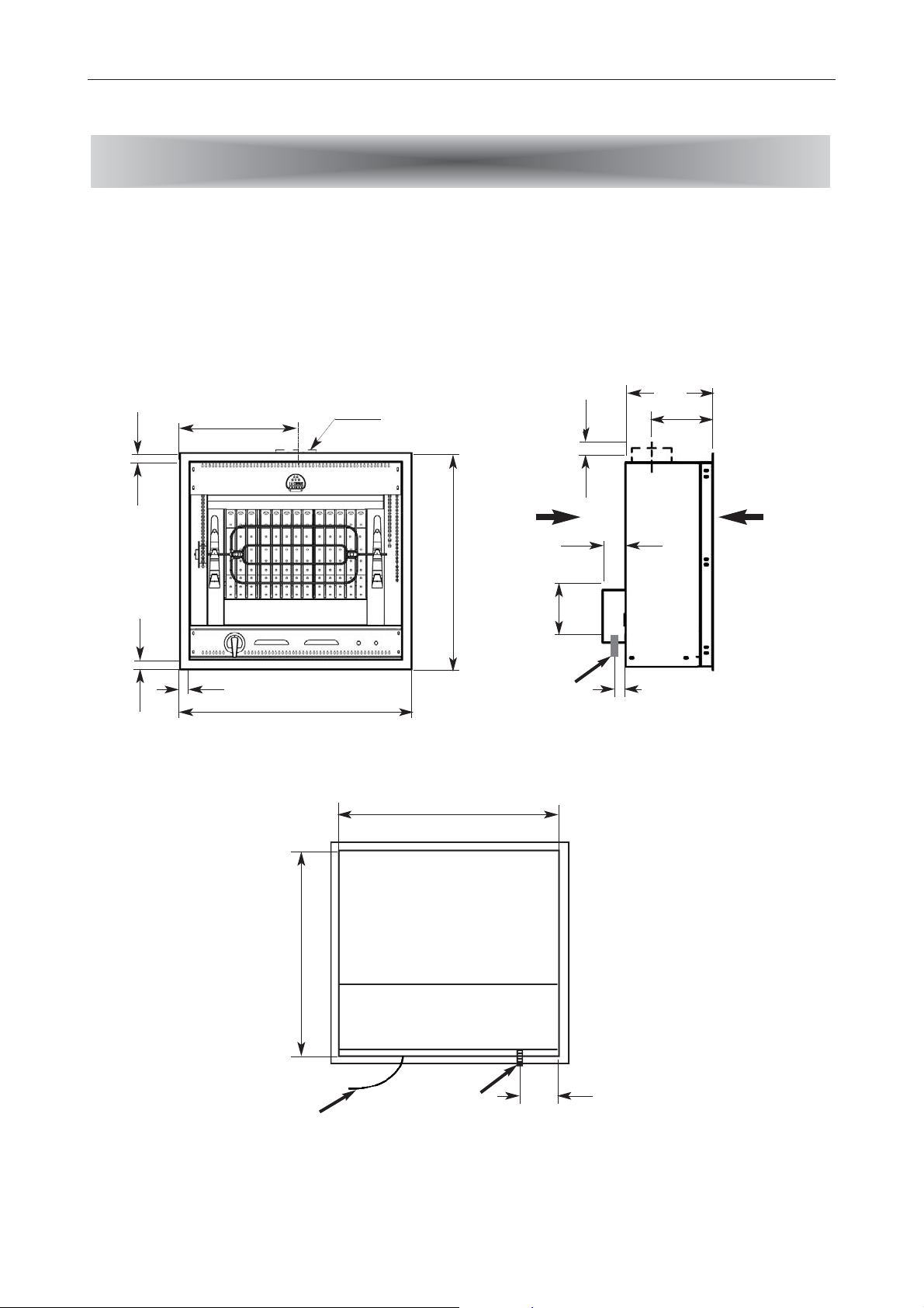
LA BROCHE FLAMBERGE
Description
755
200
30
50
30
30
805
715
750
~ 35
~ 160
100
310
205
402,5
FF
139
Gas inlet
G 1/2 (15/21)
for BFG
Gas inlet
G 1/2 (15/21)
for BFG
Electrical cable
230 V a.c. (BFG or BFE)
400 V a.c. 3 N (BFE)
All dimensions are
given in mm
Side B
Side B
Side A
Side A
Page 7

The "Broche Flamberge" is a rotisserie fr
om the "La Cornue"
line, designed for non-combustible built-in installation. It
consists mainly of a heating source (gas burner or electric element) and an electrical motor for the rotisserie. It is delivered
with the following accessories:
— 1 sauce tray
— 2 flat rods,
— 1 English-style rod
— 1 sauce spoon,
— 1 fork,
The "Broche Flamberge" comes out in 2 models:
— Electrical model, ref. BFE- - 00E00 ;
— Gas model, ref. BFG- -00E00, for use with either natural
or butane / propane gas at the following supply pressures:
- Natural gas G 20 / G 25 - 20 / 25 mbar
- butane/propane gas G30 / G31 - 28-30/37/50 mbar
The following table outlines the nominal electrical power and gas input ratings of the
models BFE and BFG Broche Flamberge.
General
DESCRIPTION
66
IInnssttaallllaattiioonn GGuuiiddee ""BBrroocchhee FFllaammbbeerrggee""
DESCRIPTION
Volume Flow
Rate
Mass Flow Rate
MMooddeell BBFFEE-- --0000EE0000
4 660 W
—
MMooddeell BBFFGG-- --0000EE0000
60 W
12 000 W
1,27 m3/hour
1,48 m3/hour
0,93 kg/hour
0,946 kg/hour
Electrical power
Heat Flow
Flat rod
English-style rod
Natural gas (G20 - 20 mbar)
Natural gas (G25 - 20 mbar)
Propane gas (G31)
Butane gas (G30 - 50 mbar)
1. GENERAL
Page 8

Broche Flamberge
— Height: 715 mm
— Width: 750 mm
— Depth: 310 mm for electrical model
410 mm for gas model
— Weight: 60 kg
Built-in Opening
— Height: 725 mm
— Width: 760 mm
— Depth: 420 mm minimum
Frame
— Height: 755 mm
— Width: 805 mm
DESCRIPTION
Dimensions
IInnssttaallllaattiioonn GGuuiiddee ""BBrroocchhee FFllaammbbeerrggee""
77
Housing enclosure
Natural discharge
diameter 139 mm
Broche Flamberge
Fresh air inlets
(for BFG)
2. DIMENSIONS
Page 9

In order to be able to install your appliance as soon as it is delivered, you must check that
the layout of your kitchen and your gas and electricity supplies are adapted.
1.1. Ventilation
The “La Broche Flamberge” spit is not intended to be connected to a ventilation shaft or
ventilation system for combustion products leading to the outside. It is therefore vital that
the room where the spit is to be installed has excellent ventilation, i.e. to the outside
- for hot air, vapour and burnt gases – and a fresh air inlet.
Do not use an air recycling system.
A flow rate of at least 4 cubic metres per hour of fresh air per KW of gas heat power is
necessary to guarantee an adequate combustion air supply.
The external evacuation system must consist of fixed aerators, flipping glass panes,
vapour extractors or extractor hoods. We advise you to adopt one of the latter two
solutions.
Recommended power: 500 m3/h minimum or 10 to 15 times the volume of air in the
room per hour.
"La Cornue" can supply models of customized hoods in materials matching your cooker or
extractors that can be integrated into a hood manufactured by the user.
Fresh air inlet: to be efficient, this must be located either directly at the back and front
of the alcove (see diagrams 5 and 7), or at the back or front of the alcove and in a radius
of 2 to 3 metres at ground level.
1.2. Fitting the spit
The “La Broche Flamberge” spit is intended for installation in an alcove made of bricks,
tiles or other non-combustible material. This alcove must have the following
dimensions: Height: 725 - 730 mm
Width: 760 - 770 mm
Depth: 420 mm minimum
A frame fits over the edge of the alcove.
The “La Broche Flamberge” spit must be attached to the frame on the front by 4 screws.
The position of these screws is established by the installer according to the appearance or
the arrangement of the wall covering.
Safety
BEFORE DELIVERY
88
IInnssttaallllaattiioonn GGuuiiddee ""BBrroocchhee FFllaammbbeerrggee""
BEFORE DELIVERY
1. SAFETY
Page 10

The accessible parts are hot when in use: ensure that all combustible material is at least 2
m away from the appliance (in front, above and at the sides). It is forbidden to place
the spit under a hood made of wood or other combustible material.
The appliance must be well ventilated, with several fresh air inlets, and hot air outlets on
the front and rear of the appliance.
Furthermore, we advise you to connect your Flamberge to a natural ventilation shaft
(separate chimney) to evacuate the hot air correctly. The Flamberge must never be
connected to a motorized hood.
The “La Broche Flamberge” spit is delivered with a 139 mm diameter connection collar.
Leave a minimum of 100 mm between the wall and the rear of the Flamberge.
As an option, the “La Broche Flamberge” spit can be supplied in a “ready to use” version
with an enamelled or stainless steel surround. Ventilation requirements for this version
are identical to the fitted version.
The “ready to use” “La Broche Flamberge” spit can only be installed on or against non-
combustible surfaces.
Voltage: 230 volts in single-phase, for the BFG- -00E00 model
230 volts in single-phase of 400 volts in 3-phase + neutral,
for the BFE- -00E00 model
Safety: the electrical supply must be grounded and must be equipped with a
protective circuit breaker compatible with the appliance’s power rating. In
high-risk regions, an additional protection against natural electrical phenomena
(lightning) must be used.
Power: for the BFE- -00E00 (electric) model, you should check that the power of your
electrical installation is adequate, given the other electrical appliances already
installed. The table on page 10 indicates the power and current required by the
“La Broche Flamberge” electric spit.
Plug connection is not recommended in view of the power of the BFE- -00E00
(electric) model. The connection will be made using a flexible cable directly connected to
the circuit breaker outlet via a junction box. Space must be left for a continuity box, with
terminal bar - preferably of the anti-shearing type – located on the right behind the “la
Broche Flamberge” spit.
The gas must be supplied via a rigid metallic pipe, terminated by an easily accessible
manual shut-off valve, installed on the supply side of the connection.
BEFORE DELIVERY
Electrical supply
IInnssttaallllaattiioonn GGuuiiddee ""BBrroocchhee FFllaammbbeerrggee""
99
2. ELECTRICAL
SUPPLY
3. GAS SUPPLY
Page 11

This valve must be installed bearing in mind that the gas inlet is located on the rear lefthand side of the appliance.
When all of the work has been carried out on your gas supply network, perform a
functional test before connecting the “La Broche Flamberge” spit. This will ensure
that no metallic burrs can enter the appliance’s gas supply pipe and thus obstruct the
burners.
This paragraph does not concern the BFG- -00E00 gas-only model, for which there are no particular
electrical connection requirements, the only connections being those of the 60 W motor.
The “La Broche Flamberge” spit is delivered ready equipped with a flexible cable
consisting of 3 (230 V, single-phase) or 5 (400 V, 3-phase) conductors, 1.50 m in length,
ready for connection to a single-phase or 3-phase + neutral supply, according to the
indications on the order form.
•All electricity supply circuits must be disconnected before accessing
the connection terminal boxes.
If the “La Broche Flamberge” spit is connected to a different type of power supply at a
later date, the wiring must be modified accordingly, as per the following settings:
- Unscrew the cover at the rear of the appliance to access the connector block to
which the heating elements are connected.
- For a 230 V Single-phase supply (1 phase + neutral + ground), shunt the Ph1, Ph2
and Ph3 studs, and then connect the cable conductors as follows:
- the neutral on N,
- the phase on Ph1,
- the ground on T (yellow/green).
Electrical connection
CONNECTIONS
1100
IInnssttaallllaattiioonn GGuuiiddee ""BBrroocchhee FFllaammbbeerrggee""
CONNECTIONS
MMooddeell
44 666600
2200 22,,55 33GG22,,55 1100 11,,55 55GG11,,55
BBFFEE-- --0000EE0000
Total Power
in Watts
Current
in Ampères
Nominal
cable sec-
tion
in mm
2
Cable refe-
rence
HH0077 RRNN--FF
Current
in Ampères
Nominal
cable sec-
tion
in mm
2
Cable refe-
rence
HH0077 RRNN--FF
Power and current for electrical model BFE -- 00E00
( * phase 1 and 2 - heating element 2300 W each ; phase 3 - motor 60 W )
230 V a.c. Power supply
(1 Ph + N + T)
400 V a.c. 3N Power supply
(3 Ph + N + T) *
1. ELECTRICAL CONNECTION
Page 12

- For a 400 V 3-phase supply (3 phases + neutral + ground):
- connect the neutral to N
- the other three connection cable conductors to studs Ph1, Ph2 and Ph3, (phases),
- the ground on T (yellow/green).
REMINDER: the appliance should be connected to the main power supply via terminal
blocks (preferably of the anti-shearing type) and not by means of simple plugs.
Insert the cable below the hot air outlets at the back of the “La Broche Flamberge”
spit, never in front of them.
This chapter only concerns the BFG- -00E00 “La Broche Flamberge” gas spit.
Your “La Broche Flamberge” spit is delivered with equipment adapted to the type of gas
supply specified when ordering (natural gas, butane or propane), and according to the
country where the spit is to be installed. In most cases, only the injector needs to be
changed if a different type of gas is used. However, it may be necessary to adjust the “bypass” screw and the pilot light.
See page 14 for the table summarising the injectors to be used for each type of gas, the
country of installation and injector replacement instructions.
If no particular instructions are specified in the order, the appliance is equipped
with injectors for natural gas G20 (pressure: 20 mbar).
The type of gas for which the appliance is equipped is indicated on a label at the
rear of the appliance, near the gas supply pipe.
Connection to the previously installed shut-off valve must be made using a rigid
metallic tube installation, whatever type of gas is used.
The “La Broche Flamberge” spit is connected to the gas supply using a G ½ thread
male threaded coupling (previous reference: 15/21).
If a sealing compound has to be used, we recommend using LOCTITE 542.
If it is impossible to connect the spit using a metallic tube, only certified flexible
hoses with mechanical coupling may be used.
CONNECTIONS
Gas connection
IInnssttaallllaattiioonn GGuuiiddee ""BBrroocchhee FFllaammbbeerrggee""
1111
2. GAS CONNECTION
230 V single-phase 400 V 3-phase
T = Ground
N = Neutral
Ph1 = Phase 1
Ph2 = Phase 2
Ph3 = Phase 3
Page 13

The hose must not pass behind, in front of or close to a hot air outlet. It must not be
crushed or kinked.
Recommended hose: Approved TUBOGAZ hose
It is forbidden to connect our gas appliances with flexible hoses mounted on hose
tailpieces.
For appliances operating with BUTANE / PROPANE gas, use two cylinders with an
automatic reversing switch or an outdoor tank, and a standard regulator adapted to
the total flow rate for your model and the gas pressure.
We advise you to use a 2 kg/h minimum regulator.
As a general rule, an additional safety margin corresponding to 20 – 30% of the
appliance’s maximum flow rate must be respected.
To guarantee constant pressure from the gas supply, the regulator should not be
placed more than 2 m from the appliance.
Each appliance must have its own regulator.
This chapter only concerns the “La Broche Flamberge” gas spit. For the electric models, only 15 to 20
minutes preheating is required before installing the meat to be roasted.
The “La Broche Flamberge” gas spit is fitted with a shut-off tap with thermocouple and
pilot light: if the pilot light should accidentally go out, the gas supply is automatically shut
off after a few seconds.
To ignite the spit proceed as follows:
— push the control lever and turn it to the left to the "star" position, whilst at the
same time holding a large lighted match to the pilot light located on the left-hand side
above the gas burners.
— hold the lever down for another 20 seconds or more to activate the safety mechanism.
— release the lever: the pilot light remains lighted and the safety mechanism is then
operational.
If the pilot light goes out, repeat the procedure, holding the lever down slightly longer. When
the system is new, the safety mechanism takes longer to activate than normal.
— to ignite the burners, press the lever and turn it to “high flame”. The flame can then be
adjusted to the required strength.
— to switch off the flame, set the lever to “0”.
15 to 20 minutes preheating is required before installing the meat to be roasted.
Tests
IGNITION
1122
IInnssttaallllaattiioonn GGuuiiddee ""BBrroocchhee FFllaammbbeerrggee""
IGNITION - ADJUSTMENTS
1. TESTS
Page 14

All adjustments are made before leaving the factory to ensure an optimal setting.
However, after changing an injector for use with a different type of gas supply, the “low”
flame and pilot light settings should be adjusted.
All settings and injector replacements should be carried out by a qualified
professional.
After any intervention on the gas circuit (adjustments, injector replacements,
etc) the system should be checked for tightness, according to current standards.
2.1. Adjusting the “low” flame setting
Only the burner “low flame” setting can be modified by the following procedure:
1. Remove the control lever by unscrewing the screw (a)
which holds it in place.
2. Remove the lower plate by unscrewing the screws (b)
blocking it.
3. Re-install the control lever; light the burner and turn the
lever to the "low flame" position.
4. Remove the control lever again and using a screwdriver,
turn the slotted screw (A) located on the body of the tap (B)
to the left to increase the gas flow or to the right to
reduce it.
Re-install the lever to switch off the burner.
Comment: the flame height must not be more than a third of the height of the hearth.
5. Re-install the lower plate and the control lever, tightening the appropriate screws.
IGNITION
Adjustments
IInnssttaallllaattiioonn GGuuiiddee ""BBrroocchhee FFllaammbbeerrggee""
1133
a b
2. A
DJUSTMENTS
A
B
Page 15

Warning: Make sure that there is enough room between the lever and the lower plate to
allow the lever to be pressed down before turning when lighting the burner.
2.2. Adjusting the pilot light
The “La Broche Flamberge” spit is fitted with a pilot light which is adjusted before
leaving the factory to ensure an optimal setting.
The pilot light should be adjusted after changing an
injector for use with a different type of gas supply from
that initially installed.
Adjustment procedure:
1. Unscrew the plug (A) with a N° 11 spanner.
2. To adjust the length of the flame, tighten or loosen the
screw inside the body of the pilot light using a
screwdriver.
WARNING: the flame must remain long enough to heat
the thermocouple.
3. Adjust the flame combustion using the air inlet ring
(B).
The burner injector reference differs according to the type of gas and country of
installation.
The following table indicates which injectors should be used following a change in the gas
supply or a house move.
Injectors
IGNITION
1144
IInnssttaallllaattiioonn GGuuiiddee ""BBrroocchhee FFllaammbbeerrggee""
AT, CH, DK, ES, FI, GB,
GR, IE, IT, PT, SE
NATURAL
II
NNJJEECCTTOORRSS
Country
Gas
Category
Gas type
G20 20
LU
260
G20 / G25
2E
G25 25
NL2L
Pressure
(mbar)
20 / 25
BE, FR2E+
G20 20
2H
170
G20 20 DE
20
DE
2ELL
G25
BE, CH, ES, FR, GB, GR,
IE, IT, PT
G30 / G31
28-30 / 37
DK, FI, NL, NO, SE
30
3+
BUTANE PROPANE
170
BUTANE -
PROPANE
G30
3B/P
150
PP
RRIIMMAARRYY AAIIRR
AADDJJUUSSTTMMEENNTT
((mmmm))
+ 1
++ 11
++ 11
-- 11
AT, CH, DE, LU
G30
50
3B/P
3. INJECTOR
REPLACEMENT
B
A
Page 16

The injectors are always replaced in the following sequence:
1. To access the injector, remove the rear cover from the “La Broche Flamberge” spit by
unscrewing the retaining screws.
2. Screw the adjusting cone (A) and insert it into the mixing tube (B) in order to free
sufficient space to unscrew the injector.
3. Unscrew the injector (C) using a N° 17 spanner.
4. Insert the injector corresponding to the new gas supply and screw it in.
5. Ignite the burner and adjust the air inlet by screwing or unscrewing the adjusting cone
(A) until you obtain a slightly blue flame showing no separation: separation of the flame
indicates that there is too much air.
6. Then block the adjusting cone with the lockwasher (D).
IGNITION
Injectors
IInnssttaallllaattiioonn GGuuiiddee ""BBrroocchhee FFllaammbbeerrggee""
1155
KKeeyy::
AT: Austria
BE: Belgium
CH: Switzerland
DE: Germany
DK: Denmark
ES: Spain
FI: Finland
FR: France
GB: Great Britain
GR: Greece
IE: Ireland
IT: Italy
LU: Luxemburg
NL: Netherlands
NO: Norway
PT: Portugal
SE: Sweden
+ 1
B D A C
- 1
**
Page 17

Cock with thermocouple and pilot:
- To light the pilot, turn the control knob 1/6 of a turn, press it and keep down a few
seconds to heat the thermocouple.
- When the pilot is on, turn the knob to the "HIGH" position.
Your Broche Flamberge electric has 2 selector switches. On position "1" the corresponding
heating elements are lighted. On position "0" the elements are switched OFF.
To light the Broche Flamberge electric you have to operate both left and right switch. The left one
is lighting the left heating elements and the right switch the right heating elements.
On each side an indicator light is showing wether the elements are working (red light if selector
switch put on position "1").
Lift the switch on the right-hand side of the rotisserie to start driving the motor.
Your motor is protected by a fuse 1 Amp situated near the switch controlling the motor.
For the horizontal rods, engage the corresponding chain at the desidered height into the wheel, and
rest the tip of the rod on the matching hook. On the drive wheel side, the rod should rest only on the
chain. It is recommended to center the roasts on the rod.
All types of meat that can be put on a spit, such as chicken, turkey, duck, hare, etc… should be
supported by square or flat rods. Secure the meat with the forks supplied to that end.
For red meat, or sides that are difficult to balance on the rod, use the English-style rod.
5. HOW TO USE THE VARIOUS RODS
4. POSITIONING OF THE RODS
3. O
PERATION OF THE RODS
2. IGNITION - BROCHE FLAMBERGE ELECTRIC
Ignition
FUNCTIONING
1166
IInnssttaallllaattiioonn GGuuiiddee ""BBrroocchhee FFllaammbbeerrggee""
FUNCTIONING
1. IGNITION - BROCHE FLAMBERGE GAS
Page 18

White meat, such as poultry, veal, pork, can be placed in the rotisserie without preheating it.
For red meat, such as joints of beef or lamb, it is recommended to preheat the rotisserie for about
15 - 20 minutes, before placing the roast. This will ensure that the outside of the meat will be properly
sealed.
Leave the rotisserie on the "HIGH" position for 10 minutes, then reduce the temperature by
placing the knob on the "LOW" position (gas model only).
Oil regularly the whole gears (gearwheels, chains, …) as well as the rods (every 3 months
approximately).
It is recommended not to touch the bunches of ceramic fibers, as this may damage them.
Pay attention not to touch the gears during functioning.
8. IMPORTANT
7. CLEANING
6. COOKING
FUNCTIONING
Cooking
IInnssttaallllaattiioonn GGuuiiddee ""BBrroocchhee FFllaammbbeerrggee""
1177
Page 19

WARRANTY (3 YEARS)
Following receipt of full payment for our
goods, our appliances are guaranteed three
years from the invoice date against any
structural faults and any material defects. The
warranty excludes improper use of the
appliance or a non-compliant installation.
Intervention and travel costs will be billed in
this event.
If our goods were to dysfunction, the buyer
then has to contact us once he has ensured
that it is not due to a non-compliant
installation or abnormal use in order to
decide with us how the appliance should be
repaired. The appliance should be cleaned
and clean prior to any intervention.
Any complaints with regard to the state, the
presentation or the non-compliance of our
goods should be addressed to our
headquarters by recommended letter with
acknowledgement of receipt within a
maximum of eight days following delivery.
The application of the warranty will be
subject to LA CORNUE SAS receiving a
certificate stating that the material has been
installed by a professional in accordance with
the current technical and safety standards.
Under this warranty, the seller shall replace at
no cost the parts recognized as faulty by its
technical department. This warranty covers
all labour costs with the exception of travel
expenses.
The warranty period specified above shall not
be extended if faulty parts need to be
replaced.
This warranty shall cease to apply:
- If the operational defect is the result of an
unauthorized intervention on the appliance;
- If the faulty operation is due to normal wear
and tear of the appliance or from negligence
or insufficient maintenance by the buyer;
- If the faulty operation is due to force
majeure.
LA CORNUE SAS shall not be held legally
responsible in these three cases.
The seller’s guarantee and his responsibility
for products shall be limited to repairs to any
defects as stipulated in the above conditions.
As expressly agreed between the contracting
parties, the seller’s responsibility in the event
of an operational fault shall be limited to the
above provisions, especially with regard to
concealed defects as well as material and
immaterial damage.
In all cases, the buyer may not suspend
payment if he lodges a complaint about the
quality of the goods.
The goods are always transported at the
buyer’s or his representative’s own risks. It is
therefore their responsibility to check them
upon arrival and, if necessary, to lodge a
complaint with the haulier. After having
expressed specific established reservations on
the delivery slip upon receipt, the buyer must
confirm them by recommended letter to the
haulier within two days of receipt (Article
105 of the Commercial Code).
We cannot in any event honour this warranty
if these requirements are not met.
1188
After- Sales Department:
- Covered by the warranty:
tel: +33 (0)1.34.48.36.15 fax: +33 (0)1.34.48.52.31
- Not covered by the warranty (appliance older than three years):
tel: +33 (0)1.47.37.56.00 fax: +33 (0)1.47.39.10.49
Page 20

La Cornue 1908
Ateliers La Cornue
14, rue du Bois du Pont - Z.I. les Béthunes
95310 Saint-Ouen l'Aumône - FRANCE
Adresse postale : La Cornue SAS - B.P. 99006
95070 Cergy Pontoise Cedex - FRANCE
Tél. : + 33 (0)1 34 48 36 36 - Fax : + 33 (0)1 34 64 32 65
E-mail : a.table@la-cornue.com
www.la-cornue.com
 Loading...