

Page 1

StorView
Storage Management Software
RAID Module User Guide
Part No. 90254-01A
Issue 1.0
March 30, 2007
Page 2

Notices
The information in this document is subject to change without notice.
While every effort has been made to ensure that all information in this document is accurate, the Authors
accept no liability for any errors that may arise.
No part of this document may be transmitted or copied in any form, or by any means, for any purpose,
without the written permission of the Authors.
Acknowledgments
Issue 1.0 March 30, 2007 Part No. 90254-01A
ii
StorView - RAID Module
Microsoft Windows 2003 is a registered trademark of Microsoft Corporation
StorView is a registered trademark of Xyratex.
Page 3

Contents
iii
Contents
Preface ................................................................................................................................................. vii
License Agreement ............................................................................................................................... vii
Related Documentation ....................................................................................................................... viii
Revision History ................................................................................................................................... viii
1 Introduction ..................................................................................................................................... 1
1.1 Overview ..................................................................................................................................... 1
1.2 Inter-Server Communication ....................................................................................................... 1
1.2.1 Multicast ............................................................................................................................. 1
1.3 License Manager ......................................................................................................................... 2
1.3.1 Access License Limits ........................................................................................................ 2
1.3.2 Feature License .................................................................................................................. 3
2 StorView Quick Tour ....................................................................................................................... 5
2.1 The Work Area ............................................................................................................................ 5
2.1.1 Tool Bar .............................................................................................................................. 6
2.1.2 Enclosure Section .............................................................................................................. 7
2.1.3 Array and Logical Drive Section ....................................................................................... 15
2.1.4 Server Sidebar and Top Section ...................................................................................... 17
2.2 How to Use this Document ........................................................................................................ 19
3 Embedded StorView Setup .......................................................................................................... 21
3.1 Embedded Network Settings ..................................................................................................... 21
3.1.1 Configuring Network Settings via the Wizard ................................................................... 21
3.1.2 Configuring Network Settings via the CLI ......................................................................... 24
3.1.3 Configuring Network Settings within StorView ................................................................. 24
3.1.4 Getting a New IP Address ................................................................................................ 25
4 Getting Started .............................................................................................................................. 27
4.1 Starting StorView ....................................................................................................................... 27
4.2 Upgrading the Access License .................................................................................................. 27
4.3 E-MAIL ...................................................................................................................................... 29
4.3.1 Configuring E-Mail Notices ............................................................................................... 29
4.3.2 Deleting an E-Mail Addressee .......................................................................................... 30
4.4 SNMP ........................................................................................................................................ 31
4.4.1 Configuring SNMP Traps ................................................................................................. 31
4.4.2 Deleting an SNMP Server ................................................................................................ 32
4.5 SYSLOG .................................................................................................................................... 33
4.5.1 Gathering Logs ................................................................................................................. 33
4.5.2 SYSLOG Daemon ............................................................................................................ 33
4.5.3 Operational View .............................................................................................................. 34
4.5.4 Configuring SYSLOG ....................................................................................................... 34
4.5.5 Delete a SYSLOG Server ................................................................................................. 35
4.6 Changing the Password ............................................................................................................ 36
Page 4

iv
StorView RAID Module
4.7 Monitoring Settings ................................................................................................................... 37
4.7.1 Additional Monitoring Servers .......................................................................................... 38
4.7.2 Remove Monitored StorView Server IP ........................................................................... 38
5 Storage Assistant ......................................................................................................................... 39
5.1 Assisted Automatic Configuration ............................................................................................. 39
6 Configuring a Storage Solution ................................................................................................... 45
6.1 Creating Disk Arrays ................................................................................................................. 45
6.1.1 RAID Levels ..................................................................................................................... 45
6.1.2 Terminology ..................................................................................................................... 46
6.1.3 Optimization and Drive Selection for RAID 5 and 6 ......................................................... 48
6.2 Create the Array ........................................................................................................................ 48
6.2.1 Configuring Array Writeback Cache ................................................................................. 54
6.3 Initializing the Array ................................................................................................................... 55
6.3.1 Pause/Resume the Initialization ....................................................................................... 56
6.4 Adding Hot Spare Drives ........................................................................................................... 57
6.4.1 Assigning a Global Spare ................................................................................................ 57
6.4.2 Assigning a Dedicated Spare ........................................................................................... 58
6.4.3 Removing a Spare ........................................................................................................... 60
6.4.4 Auto Spare ....................................................................................................................... 61
6.5 Create the Logical Drive ............................................................................................................ 62
6.6 Saving the Configuration ........................................................................................................... 65
6.6.1 Saving the Configuration .................................................................................................. 65
7 SAN LUN Mapping ........................................................................................................................ 69
7.1 Overview ................................................................................................................................... 69
7.2 Terminology .............................................................................................................................. 69
7.3 Accessing SAN LUN Mapping .................................................................................................. 70
7.4 Overview: SAN LUN Mapping Window ..................................................................................... 72
7.4.1 HBA Ports Name Section ................................................................................................. 72
7.4.2 ADD NEW MAP Section .................................................................................................. 73
7.4.3 SELECTED HOST HBA PORT CONNECTION Section ................................................. 73
7.5 Creating a SAN LUN Mapping .................................................................................................. 74
7.6 Deleting a SAN LUN Mapping ................................................................................................... 77
7.7 Modifying a SAN LUN Mapping ................................................................................................ 78
8 Controller Environmentals ........................................................................................................... 81
8.1 Overview ................................................................................................................................... 81
8.2 Controller Environmentals ......................................................................................................... 81
8.2.1 Status ............................................................................................................................... 83
8.2.2 Hardware/Firmware ......................................................................................................... 83
8.2.3 Configuration .................................................................................................................... 83
8.2.4 Operations ....................................................................................................................... 83
9 Controller Advanced Settings ..................................................................................................... 91
9.1 Overview ................................................................................................................................... 91
9.2 Advanced Settings .................................................................................................................... 91
9.2.1 Identity ............................................................................................................................. 92
9.2.2 Fault Tolerance ................................................................................................................ 94
9.2.3 Host Ports ........................................................................................................................ 96
Page 5

Contents
v
10 Managing the Storage Solution ................................................................................................... 99
10.1 Overview ................................................................................................................................... 99
10.2 Advanced Array Functions ...................................................................................................... 100
10.2.1 Deleting an Array ............................................................................................................ 100
10.2.2 Modifying Arrays ............................................................................................................. 101
10.2.3 Verify Parity .................................................................................................................... 101
10.2.4 Identifying Drive Members .............................................................................................. 104
10.2.5 Rebuilding an Array ........................................................................................................ 105
10.2.6 Expanding an Array ........................................................................................................ 106
10.2.7 Trust an Array ................................................................................................................. 108
10.3 Restoring and Clearing the Configuration ............................................................................... 109
10.3.1 Restoring the Configuration ............................................................................................ 109
10.3.2 Clearing the Configuration .............................................................................................. 110
10.4 Advanced Drive Options .......................................................................................................... 113
10.4.1 Accessing the Drive Information Window ....................................................................... 113
10.4.2 Locate Drive ................................................................................................................... 114
10.5 Advanced Logical Drive Functions .......................................................................................... 115
10.5.1 Viewing Unassigned Free Space ................................................................................... 115
10.5.2 Expanding a Logical Drive .............................................................................................. 115
10.5.3 Deleting a Logical Drive ................................................................................................. 117
11 Using Snapshot ........................................................................................................................... 119
11.1 Introduction .............................................................................................................................. 119
11.2 Enabling Snapshot .................................................................................................................. 119
11.3 Taking a Snapshot .................................................................................................................. 122
11.4 Mapping a Snapshot ............................................................................................................... 125
11.5 Deleting a Snapshot ................................................................................................................ 127
11.6 Performing a Snapback ........................................................................................................... 129
11.7 Disabling Snapshot ................................................................................................................. 131
12 Failover, Performance and Additional Functions .................................................................... 133
12.1 Overview ................................................................................................................................. 133
12.2 How StorView Server Failover Works ..................................................................................... 133
12.3 StorView Performance Optimization ....................................................................................... 134
12.3.1 Execution Throttle .......................................................................................................... 134
12.3.2 Scatter/Gather ................................................................................................................ 134
12.4 Time Out Issues ...................................................................................................................... 134
12.5 Additional StorView Functions ................................................................................................. 135
12.5.1 About .............................................................................................................................. 135
12.5.2 Take Control Monitoring ................................................................................................. 136
12.5.3 Rescan ........................................................................................................................... 137
12.5.4 Alarm Mute and Enable/Disable ..................................................................................... 138
13 Support and Updates .................................................................................................................. 139
13.1 Tech Support ........................................................................................................................... 139
13.2 Updating Embedded StorView ................................................................................................ 141
14 Event Logs ................................................................................................................................... 143
14.1 Overview ................................................................................................................................. 143
14.2 Accessing and Navigating the StorView Event Log ................................................................ 145
14.3 Exporting the StorView Event Log ........................................................................................... 146
Page 6

vi
StorView RAID Module
14.4 Clearing the StorView Event Log ............................................................................................ 149
14.5 Operating System Event Log .................................................................................................. 150
14.6 List of Events ........................................................................................................................... 151
14.6.1 Controller Events ........................................................................................................... 151
14.6.2 Expansion Module Events ............................................................................................. 157
14.6.3 Alarm Events .................................................................................................................. 158
14.6.4 Drive and Array Events .................................................................................................. 159
14.6.5 Controller Port Events .................................................................................................... 164
14.6.6 Enclosure Events ........................................................................................................... 166
14.6.7 StorView Server Events ................................................................................................. 169
14.6.8 SnapShot Events ........................................................................................................... 173
14.7 Failed Drives Codes ................................................................................................................ 175
14.8 SAS Fatal Error Codes ............................................................................................................ 175
15 Statistics ...................................................................................................................................... 177
15.1 Overview ................................................................................................................................. 177
15.2 Access Statistics ..................................................................................................................... 178
15.3 Command Size - Alignment Statistics ..................................................................................... 179
15.4 Read-Ahead Statistics ............................................................................................................. 181
15.5 Command Cluster Statistics .................................................................................................... 183
A Optimizing Write Performance .................................................................................................. 185
A.1 Introduction ............................................................................................................................. 185
A.2 Sequential Access ................................................................................................................... 186
A.2.1 Number of Outstanding Commands .............................................................................. 186
A.3 Access Size ............................................................................................................................. 186
A.3.1 Access Alignment .......................................................................................................... 186
A.4 Sub-Array ................................................................................................................................ 187
A.5 Multiple Drive Failures ............................................................................................................. 188
A.5.1 Faster Rebuild ................................................................................................................ 188
A.6 Summary ................................................................................................................................. 188
B Troubleshooting ......................................................................................................................... 189
B.1 Problems You May Encounter ................................................................................................ 189
C More on Snapshot ...................................................................................................................... 195
C.1 Overview ................................................................................................................................. 195
C.1.1 Terminology ................................................................................................................... 195
C.2 Overwrite Data Area ................................................................................................................ 196
C.3 Overwrite Data Area Location ................................................................................................. 197
C.4 Selecting the ODA Stripe Size ................................................................................................ 197
C.5 Overwrite Data Area Storage Capacity ................................................................................... 197
C.6 ODA Assignment ..................................................................................................................... 198
C.7 Snapshots and Caching .......................................................................................................... 198
C.7.1 Application Caches ........................................................................................................ 198
C.7.2 Operating System Cache ............................................................................................... 199
C.7.3 RAID Controller Cache .................................................................................................. 199
C.8 Virtual LUNs ...............................................................................................................
............. 199
C.8.1 Virtual LUN Numbering .................................................................................................. 199
Index ................................................................................................................................................... 201
Page 7

Preface
vii
Preface
What is in this guide
This user guide gives you the step-by-step instructions on how to setup and use the StorView Storage
Management RAID Module software.
Who should use this guide
This user guide assumes that you have a working knowledge of storage appliance products. If you do not
have these skills, or are not confident with the instructions in this guide, do not proceed with the
installation.
License Agreement
The Apache Software License, Version 1.1.
Copyright (c) 2000-2002 The Apache Software Foundation. All rights reserved.
Redistribution and use in source and binary forms, with or without modification, are permitted provided
that the following conditions are met:
1
Redistributions of source code must retain the above copyright notice, this list of conditions and the
following disclaimer.
2
Redistributions in binary form must reproduce the above copyright notice, this list of conditions and
the following disclaimer in the documentation and/or other materials provided with the distribution.
3
The end-user documentation included with the redistribution, if any, must include the following
acknowledgment:
“This product includes software developed by the Apache Software Foundation (http://
www.apache.org/).”
Alternately, this acknowledgment may appear in the software itself, if and wherever such third-party
acknowledgments normally appear.
4
The names “Apache” and “Apache Software Foundation” must not be used to endorse or promote
products derived from this software without prior written permission. For written permission, please
contact [email protected].
5
Products derived from this software may not be called “Apache”, nor may “Apache” appear in their
name, without prior written permission of the Apache Software Foundation.
THIS SOFTWARE IS PROVIDED “AS IS” AND ANY EXPRESSED OR IMPLIED WARRANTIES,
INCLUDING, BUT NOT LIMITED TO, THE IMPLIED WARRANTIES OF MERCHANTABILITY AND
FITNESS FOR A PARTICULAR PURPOSE ARE DISCLAIMED. IN NO EVENT SHALL THE
APACHE SOFTWARE FOUNDATION OR ITS CONTRIBUTORS BE LIABLE FOR ANY DIRECT,
INDIRECT, INCIDENTAL, SPECIAL, EXEMPLARY, OR CONSEQUENTIAL DAMAGES
(INCLUDING, BUT NOT LIMITED TO, PROCUREMENT OF SUBSTITUTE GOODS OR
SERVICES; LOSS OF USE, DATA, OR PROFITS; OR BUSINESS INTERRUPTION) HOWEVER
Page 8

StorView RAID Module
viii
CAUSED AND ON ANY THEORY OF LIABILITY, WHETHER IN CONTRACT, STRICT LIABILITY,
OR TORT (INCLUDING NEGLIGENCE OR OTHERWISE) ARISING IN ANY WAY OUT OF THE
USE OF THIS SOFTWARE, EVEN IF ADVISED OF THE POSSIBILITY OF SUCH DAMAGE.
This software consists of voluntary contributions made by many individuals on behalf of the Apache
Software Foundation. For more information on the Apache Software Foundation, please see, http://
www.apache.org/.
Portions of this software are based upon public domain software originally written at the National Center
for Supercomputing Applications, University of Illinois, Urbana-Champaign.
Related Documentation
• StorView Storage Management Software Installation Guide (P/N 90377-01A)
• RS-4835-F4-5404E Quick Start Guide (P/N 80449-01A)
• RS-4835-F4-5404E & RS-4835-E3-XPN Installation and User Guide (P/N 80448-01A)
• RS-1220-F4-5412E Quick Start Guide (P/N 90506-01A)
• RS-1220-F4-5412E & RS-1220-E3-XPN Installation and User Guide (P/N 90505-01A)
• RS-1220-F4-5402E Quick Start Guide (P/N 78603-03A)
• RS-1220-F4-5402E & RS-1220-E3-XPN Installation and User Guide (P/N 72814-04A)
• RS-1220-E3-5412E Quick Start Guide (P/N 90509-01A)
• RS-1220-E3-5412E & RS-1220-E3-XPN Installation and User Guide (P/N 90508-01A)
• RS-1220-E3-5402E Quick Start Guide (P/N 82903-02A)
• RS-1220-E3-5402E & RS-1220-E3-XPN Installation and User Guide (P/N 82904-02A)
• F5404E VT-100 RAID Configuration Utility User Guide (P/N 90255-01A)
• F5412E VT-100 RAID Configuration Utility User Guide (P/N 90507-01A)
• F5402E VT-100 RAID Configuration Utility User Guide (P/N 80226-03A)
• E5412E VT-100 RAID Configuration Utility User Guide (P/N 90510-01A)
• E5402E VT-100 RAID Configuration Utility User Guide (P/N 83249-02A)
Revision History
Version Date Description of Change
1.0 March, 2007 New Release.
Page 9

Introduction
1
Chapter 1
Introduction
1.1 Overview
StorView
®
Storage Management software is a full-featured graphical HTML-based software suite
designed to configure, manage, and monitor storage subsystems. StorView is built on a modular design
and currently supports the RAID Module. Other modules available in the future are separately
documented.
The RAID Module provides an extensive set of configuration and management tools. StorView’s RAID
Module is available in two versions: host-based and embedded. The host-based version is installed on
the host computer system, while the embedded version is installed on the RAID Controller.
StorView’s server component discovers storage solutions, manages and distributes message logs, and
communicates with other server components installed on the same local network and external subnet
networks. StorView has an HTML-based front end, accessed with a web browser, and provides the
interface to the end user.
StorView incorporates web server software as part of the installation, Apache 2.0, which provides the
interface between the server component and HTML interface. During installation the web server is
automatically configured and requires no further management.The installation of the web server software
is self contained and will not conflict with other web server software currently installed on your system.
1.2 Inter-Server Communication
1.2.1 Multicast
StorView’s server component uses multicasting technology to provide inter-server communication with
other servers when the Global Access license is installed. During the server’s initial start-up, it performs
a multicast registration using the default multicast IP address of 225.0.0.225 on port 9191. Once
registration is complete, the server is able to receive all packets sent to the multicast address.
Page 10

StorView RAID Module
2
All packets sent to the multicast address remain in the local network, unless an explicit server IP address
outside the subnet is added in the “Inter-Server Communication” Explicit StorView Server IPs >
Preference Settings, see 4.7 ”Monitoring Settings” beginning on page 37. The inter-server
communication abilities provide StorView with remote monitoring of other installations of StorView and
their monitored storage solutions.
StorView has the ability to communicate with any StorView installation on the local network. These other
StorView server’s are displayed on the Main screen and are listed under the “Other Servers” section.
They display the IP address, name, and a overall status of that server’s monitored storage solution. They
indicate the status of a monitored server storage solution, by the server icon changing to one of a few
different states, see 2.1.4 ”Server Sidebar and Top Section” beginning on page 17.
Each server sends a “check-in” packet in 10 second intervals. Once an initial check-in packet is received,
all StorView servers will know the existence of the other servers. If a server fails to send three check-in
packets, the other servers will mark that server as “missing.” This is indicated by a white “Server” icon
displayed on the Main screen under the “Other Servers” section.
When the server service that “owns” the monitored storage solution is down for any reason and three
check-in packets are not received, the monitoring will automatically be transferred to another StorView
server.
1.3 License Manager
StorView has two different licenses, a General Access License and the Feature License.
1.3.1 Access License Limits
The StorView General Access License which has different limits for the two RAID module versions of
StorView. The host-based version has Local Access and Global Access, and the embedded version has
Remote Access and Global Access. Refer to Section 4.2, ”Upgrading the Access License”, on page 27.
The Local Access is the default license of the host-based software. It provides the basic control,
management and monitoring of the locally attached storage solution.
The Remote Access is the default license included with the embedded version. It provides the same
functions as the Local Access license except it adds support for server failover and remote login. Remote
Access does not support features such as E-Mail notices, SYSLOG, and SNMP, however it does offer
an upgrade path to the Global Access license.
The Global Access license is offered for the above systems through a licensing program and provides
the capabilities of the Local Access features plus remote login, configuration, and monitoring, and it
provides alert notifications via E-Mail, SYSLOG and SNMP. With Global’s remote login and
management, the user can focus or log-in to a different storage solution that is not locally attached to the
host, allowing you to manage and monitor other solutions from just one location.
Page 11
Introduction
3
1.3.2 Feature License
The Feature License enables the full use of the Snapshot feature incorporated into the RAID Controller
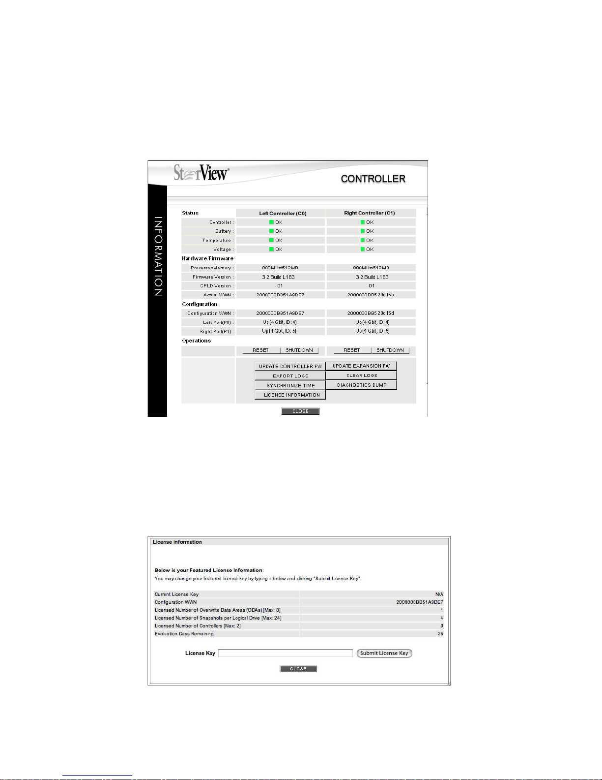
firmware. To access License Information, click the Controller icon on the Main screen and then the
LICENSE INFORMATION button at the bottom of the Controller Information window.
A limited free license is included with the system that allows for one (1) Overwrite Data Area (ODA) to be
created. Or you can purchase a full license which provides for up to eight (8) Overwrite Data Area (ODA)
to be created. With the limited free license, you can have up to four Snapshots for the single ODA. With
the maximum full license you can have up to twenty-four Snapshots for each of the eight ODAs. Each
ODA is paired to a physical Logical Drive allowing the user to create up to 4 or 24 Snapshots of their
logical drives, depending on the license.
Figure 1-1 Controller Information Screen (F5404E RAID Controller Shown)
Figure 1-2 License Information Screen
Page 12
StorView RAID Module
4
A licensing upgrade path to the maximum full feature license is provided from the License Information
screen. To upgrade, you will need to provide your Configuration WWN and Serial Number for the specific
feature to obtain a license key. The serial number is found on the label affixed to the license certificate.
You will find the Configuration WWN displayed in the License Information window.
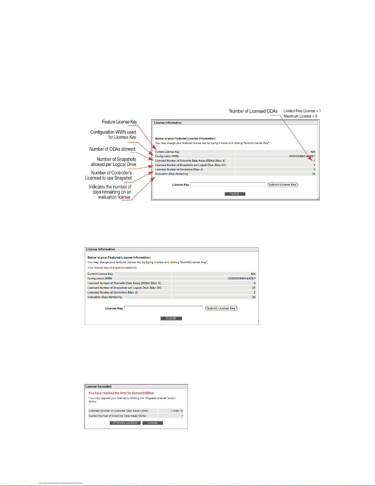
Below is an explanation of the fields of the licensing information window.
Once your license key is entered, click the Submit License Key button and the current licensing
information is displayed (Figure 1-4).
If you attempt to exceed the limited license you will receive a message. You will have the option to
upgrade the Limited Free license from that screen. Click the “UPGRADE LICENSE” button and enter a
new license key to enable the maximum license. Or you may upgrade any time by clicking the Controller
icon and then the LICENSE INFORMATION button. (Figure 1-5)
Figure 1-3 License Information Window Explained
Figure 1-4 License Upgraded
Figure 1-5 License Exceeded Message
Page 13

Quick Tour
5
Chapter 2
StorView Quick Tour
2.1 The Work Area
The StorView work area consists of the Main screen and its dialog windows for performing specific
functions. On the Main screen you will find the Toolbar, sections for Arrays and Logical Drives, an
Enclosure section and a Server section. Through the use of interactive components, animated icons, and
mouse over information windows an intuitive, easy to use approach is provided to manage your storage
solution.
Primary configuration functions include creating disk arrays, logical drives, LUN mapping and assignment
of spare drives.
You also have access to advanced features that allow for array and logical drive expansion, optimizing
controller parameters, rebuilding arrays, managing E-Mail notices of events, SYSLOG, and SNMP traps,
reviewing event logs, and analyzing system statistics.
Page 14
StorView RAID Module
6
2.1.1 Tool Bar
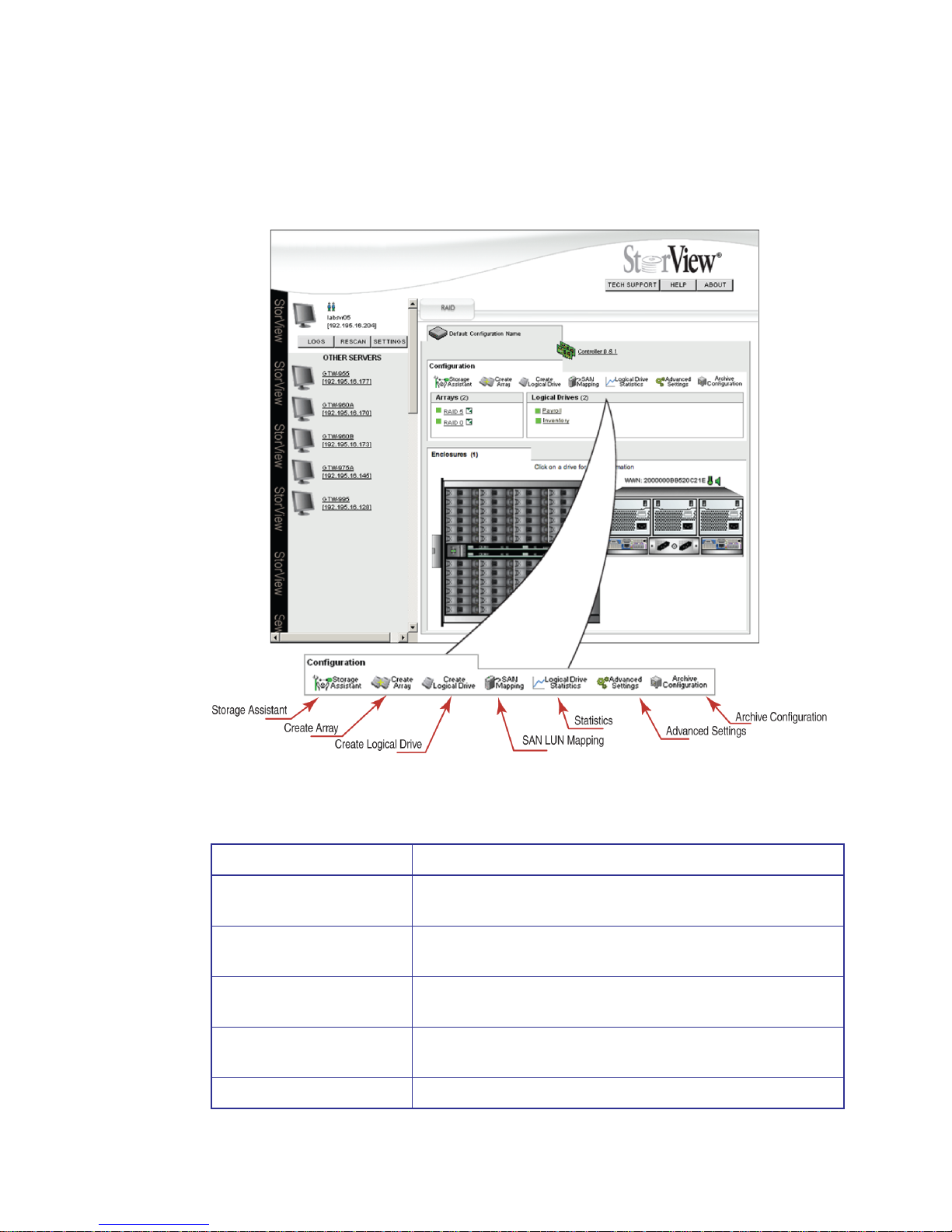
These icon buttons appear at the top of the work area and define the tool bar section of the work area.
They provide one click access to primary functions.
Note Throughout the interface, holding the mouse pointer over an icon will display a pop-up window with
information specific to the object.
Figure 2–1 Tool Bar (RS-4835-F4-5404E Model Shown)
Tool Bar Button Description
Storage Assistant This button will start the Storage Assistant wizard which will
automatically configure your storage system based on user inquiries.
Create Array This button will open the Create Array window allowing the user to
create new disk arrays.
Create Logical This button will open the Logical Drive window allowing the user to
create new logical drives.
SAN Mapping This button will open the SAN LUN Mapping panel which allows the
user to further customize logical drive availability.
Logical Drive Statistics This button opens the Statistics window.
Page 15
Quick Tour
7
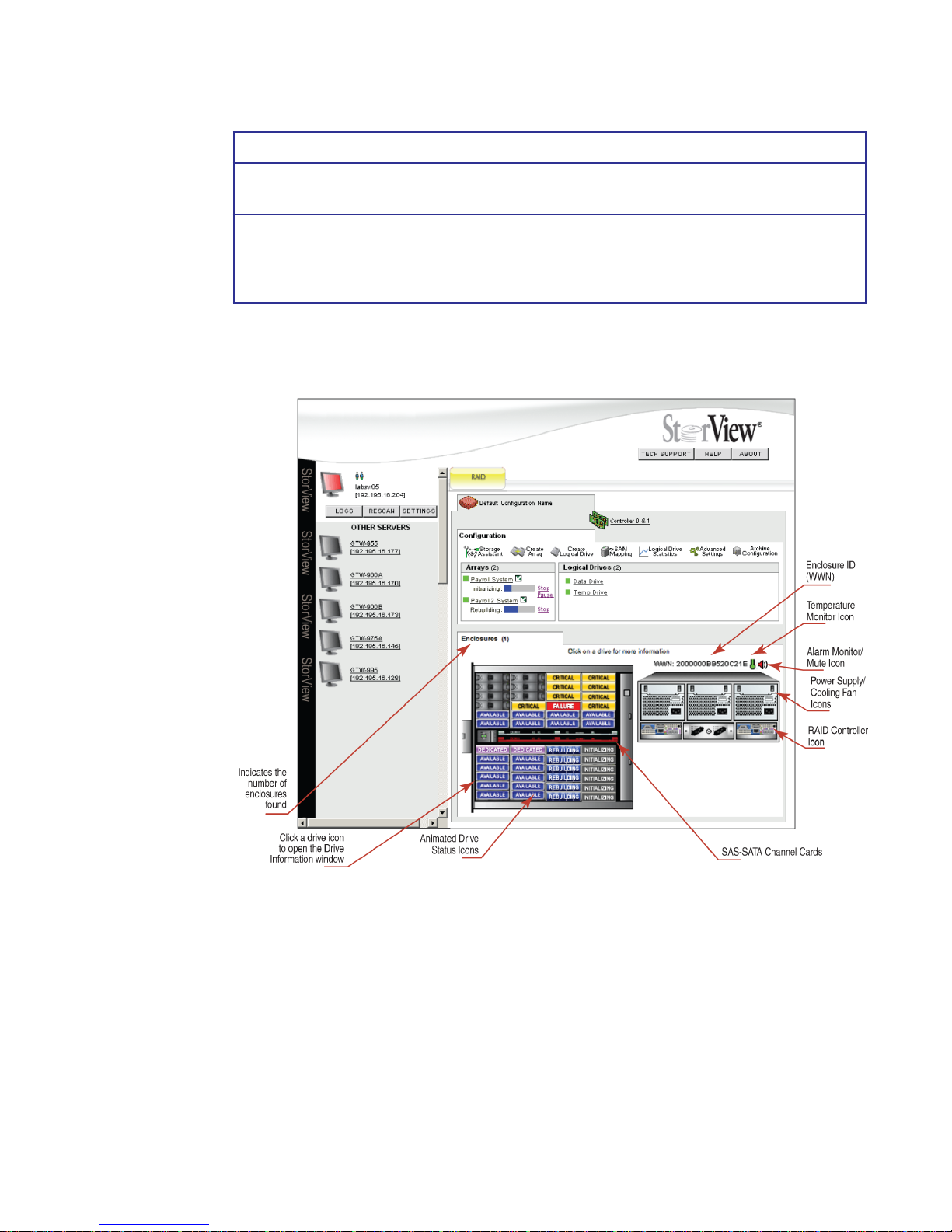
2.1.2 Enclosure Section
Advanced Settings This button opens a window from which you may change controller
parameters.
Archive Configuration This button will open a window from which you may choose to save,
restore, or clear the configuration. Note when deleting a
configuration, this will delete all arrays and logical drives as well as
the data on those logical drives.
Tool Bar Button Description
Figure 2–2 Enclosure Section (RS-4835-F4-5404E Model Shown)
Page 16
StorView RAID Module
8
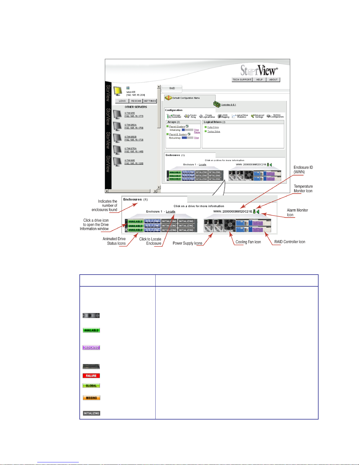
Figure 2–3 Enclosure Section (RS-1220-F4-5402E Model Shown)
Enclosure Section Description and Condition
Drive Status Icon These icons appear on the front of the enclosure on the Main screen
and provide an instant view of the status of disk drives as well as drive
location and clicking the icon will open the Drive Information window.
• Member - Disk drive is a member component of an array.
• Available - Disk drive is online and available for use in an array
or as a hot spare.
• Dedicated Spare - Disk drive is marked as a dedicated spare to
an array.
• Empty - Disk drive slot is empty.
• Failed - Disk drive has failed.
• Hot Spare - Disk drive is a global spare.
• Missing - Indicates that StorView is unable to determine the
status of the drive.
• Initializing - Disk drive is a member of an array being initialized.
Member
Available
Dedicated Spare
Empty
Failed
Initializing
Missing
Hot Spare
Page 17
Quick Tour
9
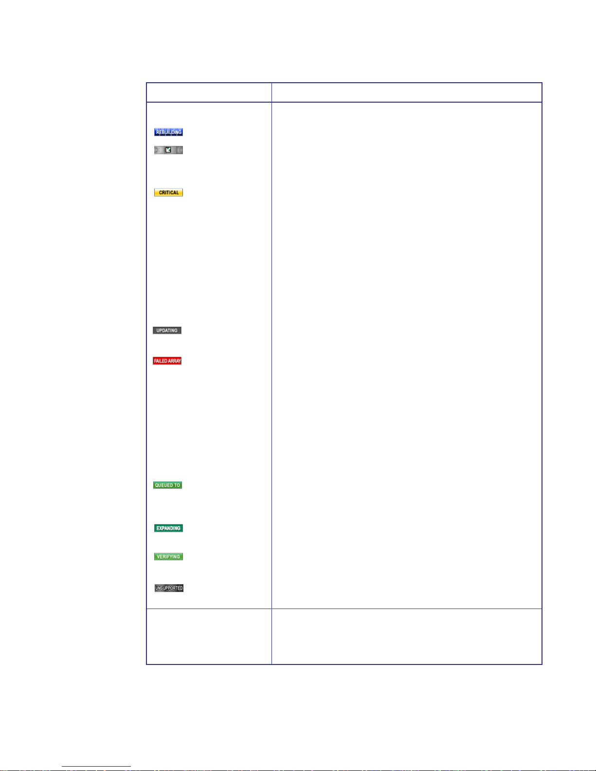
Drive Status Icon (continued)
• Rebuilding - Drive members of an array are in rebuild mode.
• Locate - Clicking the “arrow” icon next to the “specific array” in
the Arrays section will display an “arrow” icon on all the drive
members of that array in the front enclosure view.
• Critical - Drive(s) are members of a fault tolerant array and are
in a non-fault tolerant state.*
*NOTE : With RAID 6 disk arrays, the loss of a single drive does
not place the array in a non-fault tolerant state. The drive status
icon is the same for single or dual drive failures. To verify
whether the array is in a Non Fault Tolerant vs. Fault Tolerant
Warning state, identify the number of drive failures for the array.
Two drive failures will put the RAID 6 array in a non fault tolerant
state. Passing the mouse pointer over the status icon (yellow)
will display the array’s status, also in the Array Information
screen the status is displayed.
• Updating Firmware - This icon will appear when the subject
drive’s firmware is being updated.
• Failed Array Member - This icon will appear on all disk drives
that are members of an array that has failed. For example if you
remove a drive from a RAID 0 array or a drive in that array fails,
the remaining drive members will have this icon displayed
indicating that array has failed. If you accidentally remove the
wrong drive in a critical redundant array (RAID 5) instead of the
failed drive, that array will have failed and its member drives will
have this icon displayed. Re-inserting the drive that was
accidentally removed will put the drive members back to a critical
state in which the array is being rebuilt.
• Queued to Initialize - This icon is displayed on the drive
members whose array is to be initialized and is placed in a
queue for the process to be started and completed.
• Expanding - This icon is displayed on the drive members whose
array is expanding.
• Verifying - This icon is displayed on the drive members whose
array’s parity data is being verified.
• Unsupported - This icon is displayed when a drive does not
match the other drives for the array.
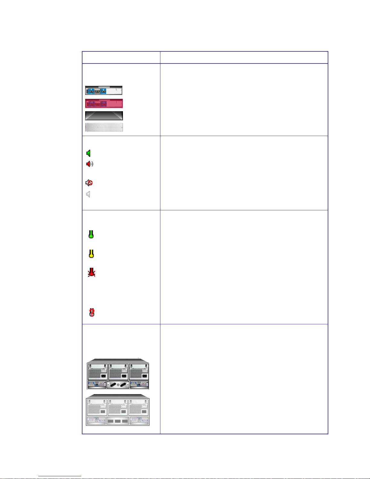
Enclosure Component Icons The following icons appear on the Main screen in the Enclosure
section. They provide an instant view of the operating status of the
enclosure components, and clicking the icons will open the Controller
Information window.
Enclosure Section Description and Condition
Rebuilding
Locate
Critical
Updating Firmware
Member Failed Array
Queued to Initialize
Expanding
Verifying
Unsupported
Page 18
StorView RAID Module
10
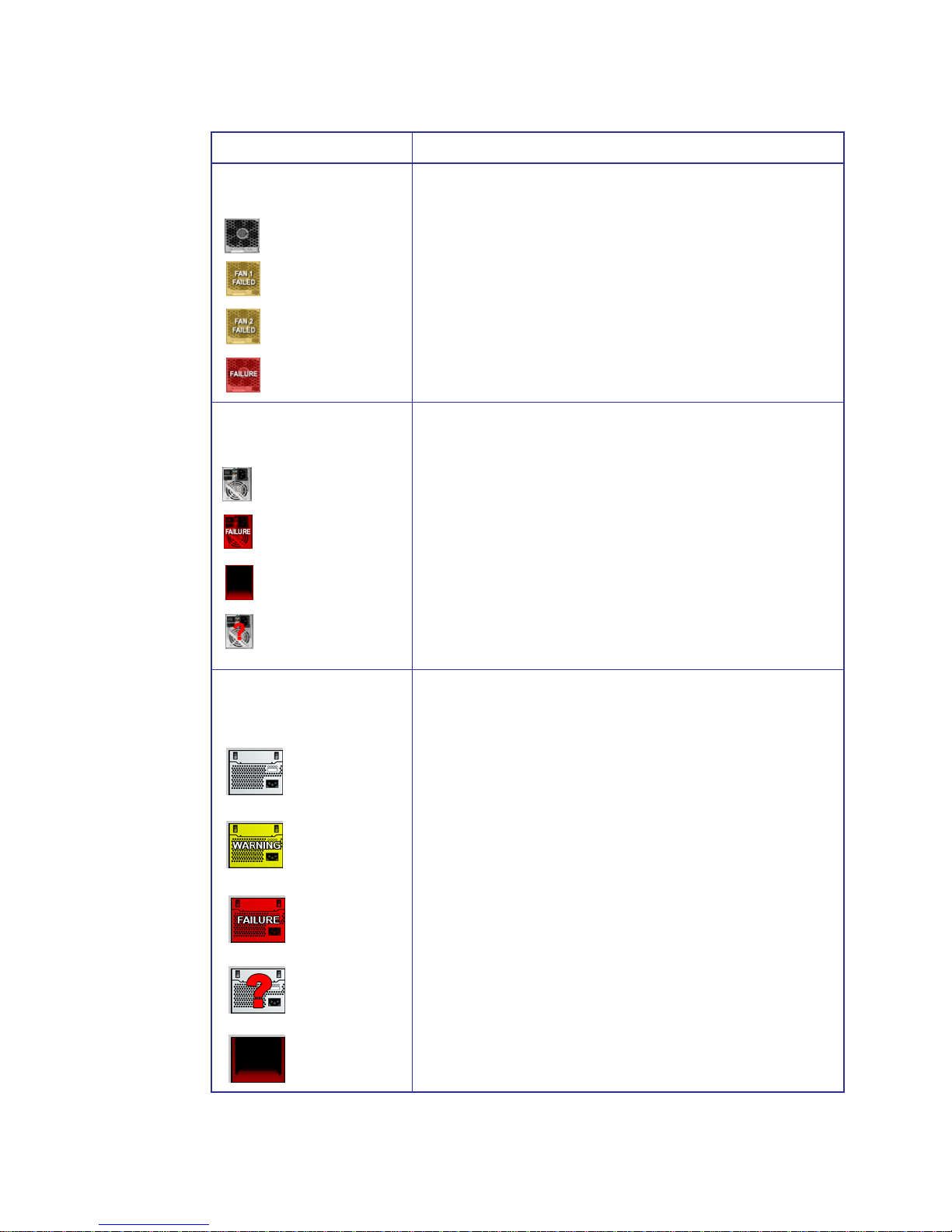
Fan Icon
(RS-1220 Enclosures Only)
• Normal - Both fans are operating normally.
• Fan 1 Failed - One fan in the fan module has failed. The fan
which failed will be indicated on the icon.
• Fan 2 Failed - One fan in the fan module has failed. The fan
which failed will be indicated on the icon.
• Failure - Both fans in the fan module have failed or the cooling
fan module has been removed.
Power Supply Icon
(RS-1220 Enclosures Only)
• Normal gray icon indicates that the power supply is operating
normally.
• A red flashing icon with “Failure” displayed indicates that the
subject power supply has failed.
• A solid red icon indicates that the power supply is missing.
• Unknown - This icon indicates the enclosure power supply
information from the SES processor or SAF-TE processes
is missing or invalid.
Power Supply/Cooling Module
Icon
(RS-4835 Enclosures Only)
• Normal - The power supply/cooling fan module is operating
normally.
• Warning - To be determined.
• Failure - To be determined.
• Unknown - The power supply/cooling fan module status cannot
be determined.
• Missing - The power supply/cooling fan module cannot be
located.
Enclosure Section Description and Condition
Fan 1 Failed
Fan 2 Failed
Failure
Normal
Normal
Failure
Missing
Unknown
Normal
Warning
Failure
Unknown
Missing
Page 19
Quick Tour
11
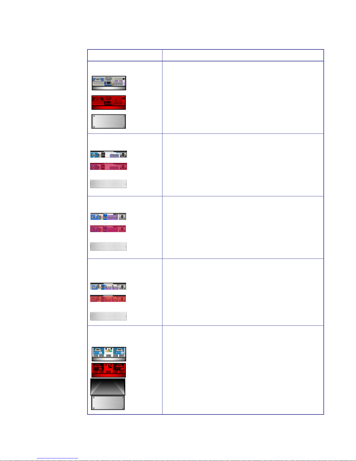
F5404E RAID Controller
• Normal - RAID Controller is operating normally.
• Error - A RAID Controller has failed in an Active-Active topology
or the backup battery has failed.
• Empty - This icon represents the empty controller slot for future
expansion. A blank plate is shown.
F5412E RAID Controller
• Normal - RAID Controller is operating normally.
• Error - A RAID Controller has failed in an Active-Active topology
or the backup battery has failed.
• Empty - This icon represents the empty controller slot for future
expansion. A blank plate is shown.
F5402E RAID Controller
• Normal - RAID Controller is operating normally.
• Error - A RAID Controller has failed in an Active-Active topology
or the backup battery has failed.
• Empty - This icon represents the empty controller slot for future
expansion. A blank plate is shown.
E5402E/E5412E RAID
Controller
• Normal - RAID Controller is operating normally.
• Error - A RAID Controller has failed in an Active-Active topology
or the backup battery has failed.
• Empty - This icon represents the empty controller slot for future
expansion. A blank plate is shown.
EBOD I/O Module
(RS-4835-E3-XPN)
• Normal - EBOD I/O Module is operating normally.
• Error - The EBOD I/O Module has failed.
• Missing - The EBOD I/O module is missing from the slot.
• Empty - The EBOD I/O module is removed and a blank plate is
installed.
Enclosure Section Description and Condition
Normal
Error
Empty
Normal
Error
Empty
Normal
Error
Empty
Normal
Error
Empty
Normal
Error
Missing
Empty
Page 20
StorView RAID Module
12
Disk I/O Module
(RS-1220-E3-XPN)
• Normal - Disk I/O Module is operating normally.
• Error - Disk I/O Module has failed.
• Missing -Disk I/O is missing from the slot.
• Empty - Disk I/O is removed and a blank plate is installed.
Alarm Monitor Icon
• This icon indicates the alarm is silent.
• This icon indicates the alarm is On (Continuous), On
(Intermittent), or On (Remind).
• This icon indicates the alarm is muted.
• This icon indicates the alarm is disabled.
Note: Clicking the icon will open a window to manage the alarm.
Enclosure Temperature Icon Enclosure temperature icon is displayed just above the rear
enclosure icon and indicates the status of the enclosure temperature.
• Normal - This icon indicates that the temperature is normal. It
appears green.
• Warning - This yellow icon indicates that the enclosure
temperature is approaching the established threshold.
• Failed - This red icon indicates that the enclosure temperature
has reached or exceeded the enclosure temperature threshold.
(If the fans are operating normally and the air flow temperature
seems normal it may be an indication that the temperature
sensor is faulty.
• Missing - This icon indicates that the information from the SES
regarding the sensors is invalid or missing.
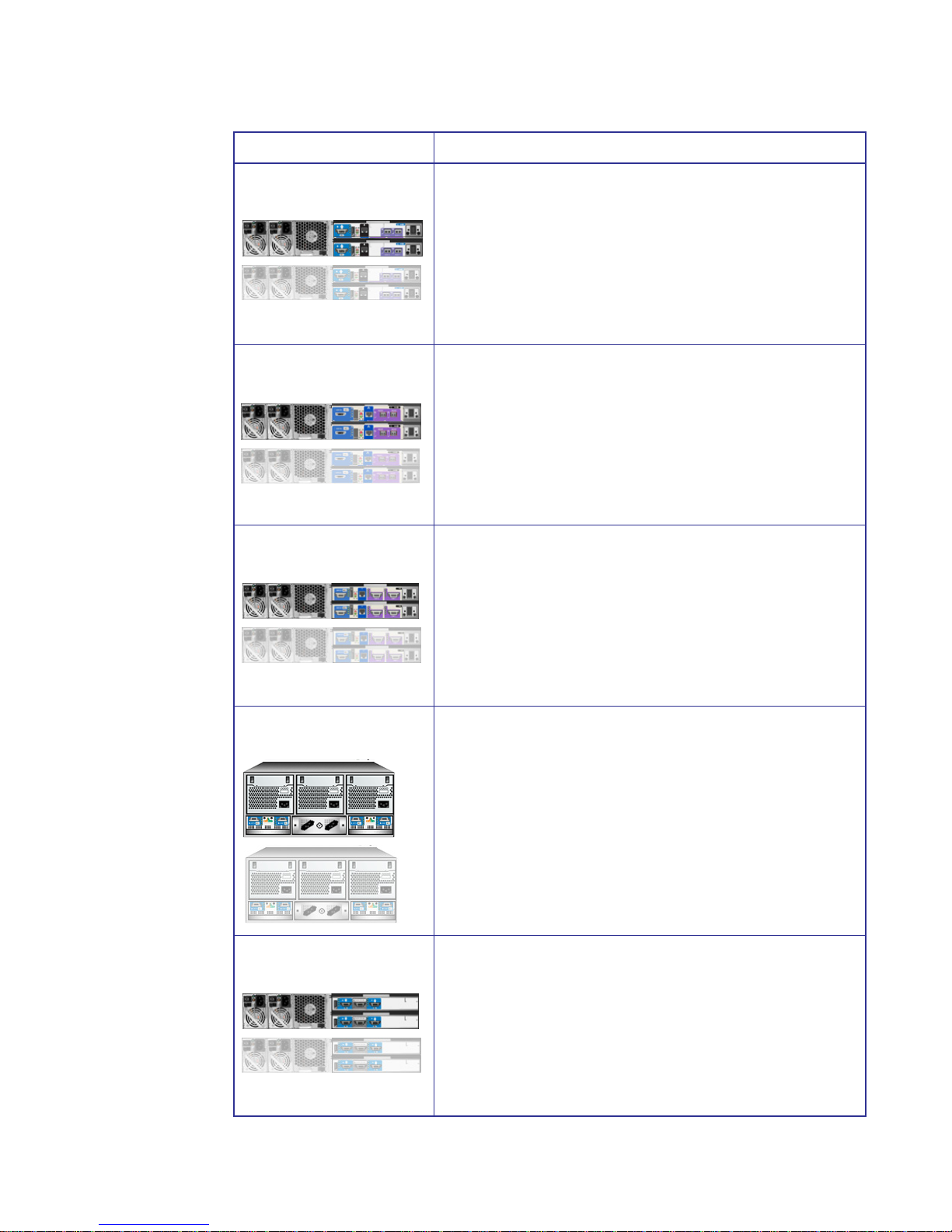
Rear Enclosure Icon
RS-4835-F4-5404E (F5404E)
Rear view enclosure icons are displayed at the bottom of the main
screen and will change shades according to enclosures state, as well
as the state of the individual components. The enclosures are labeled
above each front view to aid with identifying them in a multiple
enclosure environment.
• Normal - All components are operating normally.
• Communication Error- The SES process has lost
communication with the enclosure, indicated by the icon
becoming grey or dim. Or you have disabled “Enclosure
Support” in the Controller Advanced Settings.
Enclosure Section Description and Condition
Normal
Error
Missing
Empty
Off
On
Mute
Disabled
Normal
Warning
Failed
Missing
Page 21
Quick Tour
13
Rear Enclosure Icon
RS-1220-F4-5412E (F5412E)
• Normal - All components are operating normally.
• Communication Error- The SES process has lost
communication with the enclosure, indicated by the icon
becoming grey or dim. Or you have disabled “Enclosure
Support” in the Controller Advanced Settings window.
Rear Enclosure Icon
RS-1220-F4-5402E (F5402E)
• Normal - All components are operating normally.
• Communication Error- The SES process has lost
communication with the enclosure, indicated by the icon
becoming grey or dim. Or you have disabled “Enclosure
Support” in the Controller Advanced Settings window.
Rear Enclosure Icon
RS-1220-E3-5402E/5412E
• Normal - All components are operating normally.
• Communication Error- The SES process has lost
communication with the enclosure, indicated by the icon
becoming grey or dim. Or you have disabled “Enclosure
Support” in the Controller Advanced Settings window.
Rear Enclosure Icon
RS-4835-E3-XPN
• Normal - All components are operating normally.
• Communication Error- The SES process has lost
communication with the enclosure, indicated by the icon
becoming grey or dim. Or you have disabled “Enclosure
Support” in the Controller Advanced Settings.
Rear Enclosure Icon
RS-1220-E3-XPN
• Normal - All components are operating normally.
• Communication Error- The SES process has lost
communication with the enclosure, indicated by the icon
becoming grey or dim. Or you have disabled “Enclosure
Support” in the Controller Advanced Settings window.
Enclosure Section Description and Condition
Page 22
StorView RAID Module
14
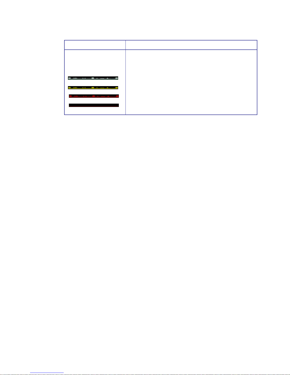
SAS-SATA Channel Card
Icons (RS-4835-F4--5404E or
RS-4835-E3-XPN)
SAS-SATA Channel cards displayed on the top view of the enclosure.
• Normal - The car is operating normally.
• Warning - Unknown
• Fail - SAS-SATA Channel card has failed.
• Missing - Indicates that the information from the SES regarding
the sensors is invalid or missing.
Enclosure Section Description and Condition
Page 23
Quick Tour
15
2.1.3 Array and Logical Drive Section
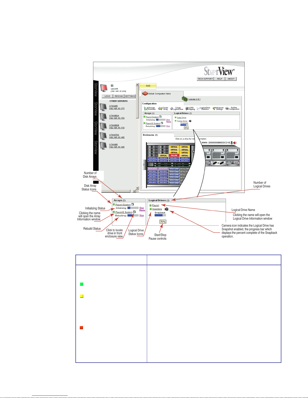
Figure 2–4 Array and Logical Drive Section (RS-4835-F4-5404E Model Shown)
Array and Logical Drive Section Description and Condition
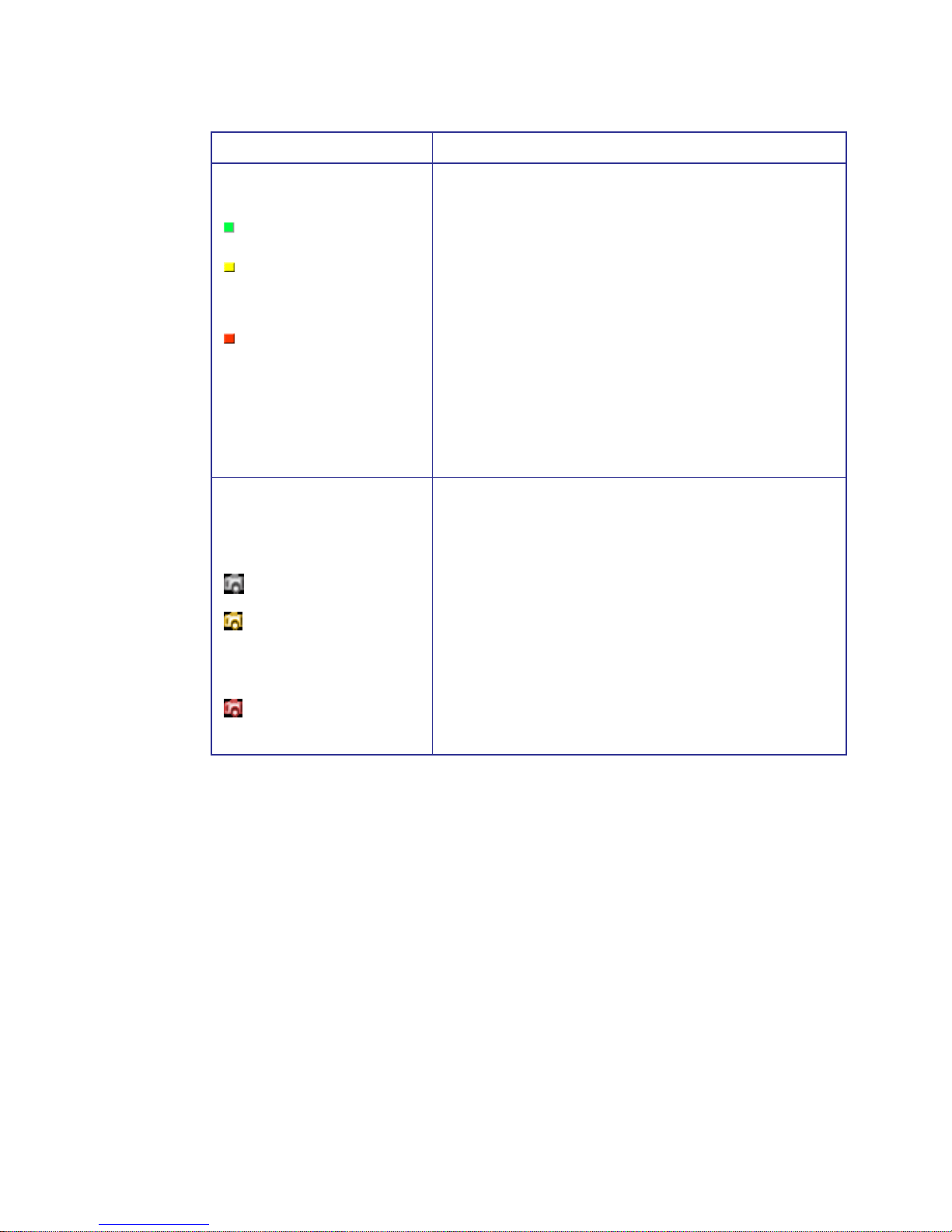
Array Status Icon These icons are found in the Array section and depict the current
state of the specific component.
• Green - Status is ok.
• Yellow - Indicates a drive component in a RAID 1, 10, 5, 6 or
50 array has failed and the array is no longer fault tolerant, or
the array is in a rebuild cycle.
For RAID 6 arrays, it indicates 1 or 2 drives have failed. See
Drive Status Icon “Critical” state.
• Red - Indicates an array is invalid or offline due to an error:
RAID 0 = One drive has failed.
RAID 1/10 = Two drives have failed from the same pair.
RAID 5 = Two drives have failed.
RAID 6 = Three drives have failed.
RAID 50 = Two drives have failed within the same sub-array.
Green (Normal)
Yellow (Warning)
Red (Error)
Page 24
StorView RAID Module
16
Logical Drive Status Icon These icons are found in the Logical Drive section and depict the
current state of the specific component.
• Green - Status is ok.
• Yellow - Indicates the logical drive is part of an array that is
degraded.
For logical drives consisting of RAID 6 arrays, it indicates 1
or 2 drives have failed. See Drive Status Icon “Critical” state.
• Red - Indicates the logical drive is part of an array which is
invalid or offline,
RAID 0 = One drive has failed.
RAID 1/10 = Two drives have failed from the same pair.
RAID 5 = Two drives have failed.
RAID 6 = Three drives have failed.
RAID 50 = Two drives have failed in the same sub-array.
ODA Status Icon This icon is found in the Logical Drive section adjacent to the
Snapshot enabled logical drive and depicts it’s current state.
During a Snapback operations, a status bar displaying the percent
complete will appear under the Logical Drive icon.
• ODA is OK.
• ODA is reaching capacity. Free up ODA space by deleting
unneeded snapshots. A warning will appear when a
minimum amount of space remains on the ODA. The specific
amount is dependant on the size of the ODA.
• The ODA has run out of space. All snapshots are invalid. In
order to resume operations, delete all snapshots.
Array and Logical Drive Section Description and Condition
Green (Normal)
Yellow (Warning)
Red (Error)
Normal
Warning
Failed
Page 25
Quick Tour
17
2.1.4 Server Sidebar and Top Section
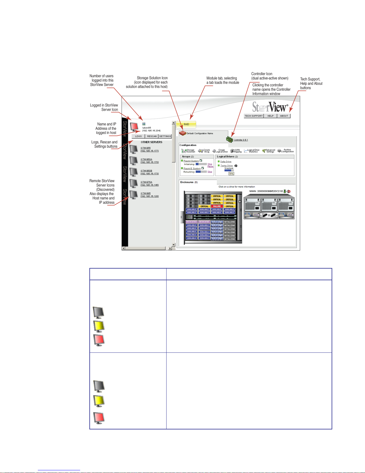
Figure 2–5 Server Sidebar Section (RS-4835-F4-5404E Model Shown)
Server Section Description and Condition
StorView Server Icon These icons will appear on the Server Sidebar section on the Main
screen. They depict the current server and discovered servers. The
icon will indicated the status of the server components by changing
its color and state.
• Normal Gray - Status is ok.
• Flashing Yellow - Indicates a server warning that a device
connected is in degraded mode.
• Flashing Red - Indicates a server error or device malfunction.
Remote StorView Servers Icon
(Global License)
• Normal Gray - Status is ok.
• Flashing Yellow - Indicates a server warning that a device
connected is in degraded mode.
• Flashing Red - Indicates a server error where a device has
malfunctioned.
Normal
Warning
Error
Normal
Warning
Error
Page 26
StorView RAID Module
18
Remote StorView Servers Icon
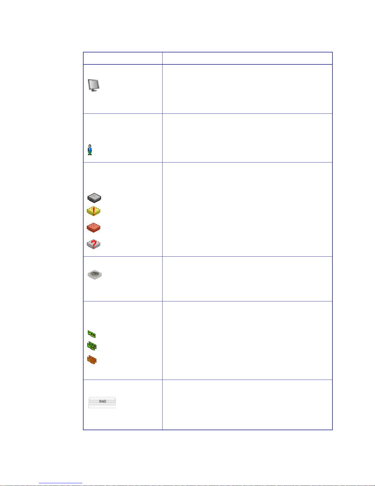
• Flashing White - The server has not responded in at least 40
seconds and is considered missing. If you would like to remove
the missing server from the list, click the Rescan button. This will
refresh the screen with a current list of discovered servers.
User Icon
(located adjacent to Server
icon)
Represents each user logged into the StorView server you are
monitoring. Placing the mouse pointer over the icon will display the IP
address, host name and the user name.
Storage Solution Icon
(displayed for each storage
solution)
You will also see the warning “!”, error, and unknown icons for
unfocused storage solutions that are being monitored as well.
• Normal Gray - Status is ok.
• Flash Yellow with red “!” - Indicates a component in the storage
solution is in degraded mode.
• Flashing Red - Indicates a component in the storage solution
has malfunctioned.
• Flashing Red with “?”- Indicates that the storage solution was
there at startup but now cannot be located.
Storage Solution: Unmonitored
This icon indicates that another StorView server is monitoring this
storage solution, or if you just performed a rescan then the StorView
servers are still determining which StorView server will take control of
the monitoring of the storage solution.
Controller Icon This icon represents the RAID Controller installed in the enclosure.
For duplex systems (Active-Active), a dual controller image is
displayed.
• A green icon represents a normal operating system.
• A flashing red icon appears if the controller’s backup battery unit
has failed, or in Active-Active topologies when the partner
controller has failed.
Module Tabs
The tab appears at the top of the Main window and when selected will
focus the monitoring and management functions to specific systems
types. This tab will flash yellow if a warning condition occurs and red
if an error condition occurs.
Server Section Description and Condition
Normal
Warning
Error
Unknown
Normal
Normal
Error
RAID Module
Page 27

Quick Tour
19
2.2 How to Use this Document
The design of this user guide is to introduce StorVIew to its users, provide an explanation of the interface
through this quick tour section and provide a step-by-step approach to configuring up the network settings
when using the embedded version. If you are using the host-based version you may skip Chapter 3.
The Getting Started chapter will walk you through starting StorView, upgrading the access license if
necessary, and configuring E-Mail, SYSLOG, SNMP, and additional monitoring.
Chapter 5 walks you through the Storage Assistant, an automated wizard tool that allows StorView to
configure your storage system. If you will be manually configuring your storage system, you may skip to
Chapter 6.
Chapter 6 will step you through the entire process of configuring the storage solution from defining disk
arrays, assigning hot spares, and configuring the logical drives.
The remaining chapters deal with the more advanced features such as Snapshot, SAN LUN Mapping,
controller environment monitoring and optimization, and modifying controller operational parameters.
You will also find information on advanced management of your storage including event logs and
statistical analysis.
Page 28

StorView RAID Module
20
Page 29

Embedded StorView Setup
21
Chapter 3
Embedded StorView
Setup
3.1 Embedded Network Settings
Note If you are using the host-based version of StorView, you may skip this chapter.
After completing your hardware set up, ensure you have a shielded Cat 5 or better Ethernet cable
connected to the controller’s networking port (StorView Embedded Module port (RJ-45)) and your
network hub or host computer Ethernet port. If your connecting to the network hub use a standard
Ethernet cable, if your connecting to your host port use a cross-over Ethernet cable. The first time you
start embedded StorView, you must configure the network settings.
Upon start-up, embedded StorView looks at the user Preferences Settings to determine if an IP address
exists. If one is defined it will initialize the network interface using that IP address.
In the event an IP address is not defined, it attempts to get a DHCP IP address. You will need to contact
your network administrator for the IP address assigned by the DHCP server. To identify the new IP
address lease, one can look for “esv0” or “esv1”’ in your DHCP Manager software.
If an IP address cannot be determined, the software will use a default IP address of “10.1.1.5” for
Controller 0 and “10.1.1.6” for Controller 1. If your network does not have a DHCP server, then set the
host IP address to 10.1.1.20 and the subnet mask to 255.0.0.0 and run the wizard again. If an error is
encountered, the embedded StorView Server will have the IP address of “10.1.1.7” assigned to it.
A tool is provided to configure new embedded StorView modules. From a Windows platform, it is
accessed via the Embedded StorView Setup Wizard link on the disc navigation menu and on Linux it is
accessed via a command line executable.
3.1.1 Configuring Network Settings via the Wizard
When the Embedded StorView Setup program is run, it will broadcast UDP packets and any embedded
StorView module will reply with UDP packets containing their information. A list of “uninitialized” systems
is displayed. Uninitialized systems are those which have not had the default user name and password
changed.
Page 30
StorView RAID Module
22
Even if a configuration is created with arrays and logical drives but the login name and password have
not been changed, it will still be considered an uninitialized system. During the process of configuring an
embedded module, you will be required to enter a “new” password and confirm that password. The
default password is the word “password.”
The embedded module is identified by its MAC and IP address. It may be more helpful during setup to
configure one embedded module at a time. You will find the MAC and IP address by accessing the VT100 RAID Configuration Utility, selecting Diagnostics then choosing StorView Embedded Module
Support. Select Enter StorView Embedded Module Menu Mode and choose View Network Settings.
1 Insert the Software and Manuals Disc into your CD drive. The autorun program will automatically start
the navigation menu.
2 Click the Embedded StorView Setup Wizard link to begin the configuration.
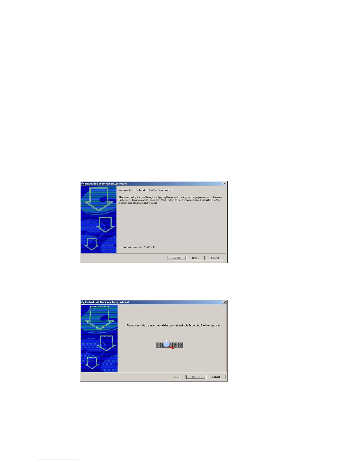
3 You are presented with a “Welcome” screen and instructions to proceed. Review the information and click
the Next button.
4 The program will begin searching for embedded StorView modules.
Those embedded modules with their default password intact will be displayed with their MAC address in
an Uninitialized list window. If all discovered embedded modules have had their default passwords
changed, then you will be taken to the “Initialized” screen.
Figure 3–1 Welcome Screen
Figure 3–2 Searching Screen
Page 31
Embedded StorView Setup
23
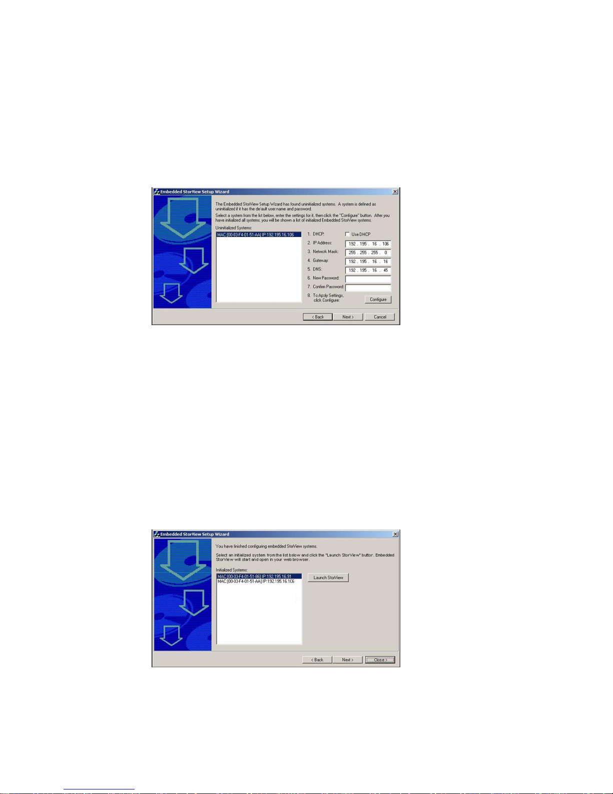
5 From the “Uninitialized” screen, select the MAC address of the embedded module you wish to configure.
If you wish to use a DHCP server to assign your IP address, click the check box “Use DHCP”.
If you wish to manually configure your network setting, enter the correction information in the appropriate
fields.
6 Enter a “new” password and confirm the new password. Click the Configure button.
7 If you have additional uninitialized embedded modules, select the next MAC address and choose the
appropriate settings from the previous steps.
Once you have completed configuring all the uninitialized embedded modules and have clicked the
Configure button, the wizard will display a pop-up message indicating all systems have been configured.
It will then re-scan for uninitialized systems and if none are found, you will be taken to the Initialized
screen. If someone plugs in a uninitialized system to the network (same subnet mask) during the time of
the rescan or resets a system’s password back to the defaults, you will be taken to the Uninitialized
screen again.
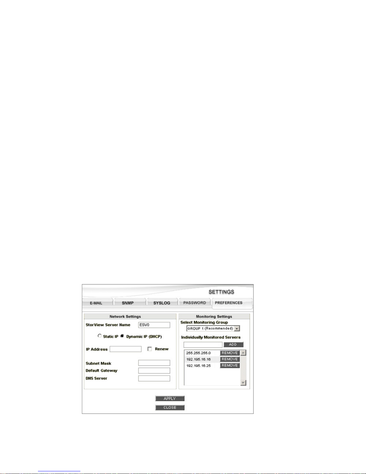
8 Select the MAC address of the embedded module you wish to start and click the Launch StorView button.
StorView will start up.
9 Your web browser will open with a login screen. Enter the login name and “new” password then click OK.
The StorView Main screen will open.
Figure 3–3 Configuration Screen
Figure 3–4 Launch Screen
Page 32
StorView RAID Module
24
3.1.2 Configuring Network Settings via the CLI
From a Linux system using a command line interface (CLI), perform the following:
1 Log in as “root.”
2 Insert the Software & Manuals Disc into your CD drive.
3 Change directories to the software location. Type:
cd [CDROM mount point path]/software/storview/embedded
4 Execute the Setup Tool. From the command prompt, type:
./esvsetupcl-linux
Embedded StorView Setup Tool. v1.0
Entering Menu Mode.
5 Follow the on screen prompts. At the conclusion of the setup you will be instructed on how to proceed.
StorView will start within your web browser.
Note Host-based StorView is started by launching your web browser and entering the IP address of the local
host followed by “:9292”. For more information, refer to the StorView Storage Management Software
RAID Module User’s Guide.
3.1.3 Configuring Network Settings within StorView
1 Click the SETTINGS button on the Main screen and select the PREFERENCES tab.
2 The StorView Server Name field will have a default name, “esv0” for Controller 0 and “esv1” for
Controller 1. If you wish to change this name, enter the desired name for this embedded StorView server.
Note If the StorView server name displays “esverr,” this indicates a problem with the embedded StorView
server module. Contact technical support.
Figure 3–5 Settings Screen - Preference Tab (Dynamic IP Selected)
Page 33

Embedded StorView Setup
25
3.1.3.1 Using Dynamic IP (DHCP)
Note StorView does not display the TCP/IP information when Dynamic IP (DHCP) is selected. You must use
a third-party network administration program to obtain this information.
To use the DHCP Server network interface setting:
1 Click the option button next to Dynamic IP (DHCP).
2 Click the APPLY button to make the changes effective.
3 Click the CLOSE button.
3.1.3.2 Using Static IP
To manually configure the network interface setting:
1 Click the option button next to Static IP.
2 Enter the desired IP address in the “IP Address” field and press the <Tab> key or click in the Subnet Mask
field.
3 Enter the desired Subnet Mask in the “Subnet Mask” field and press the <Tab> key or click in the Default
Gateway field.
4 Enter the desired gateway or router address and press the <Tab> key or click in the DNS Server field.
5 Enter the desired DNS Server IP address.
6 Click the APPLY button to make the changes effective.
7 Click the CLOSE button.
3.1.4 Getting a New IP Address
If you are set up to receive your IP address using Dynamic IP (DHCP), you can force the embedded
StorView server to obtain a new IP address from your DHCP server.
1 Click the SETTINGS button and select the PREFERENCES tab.
2 Click the Renew check box.
3 Click the APPLY button to make the changes effective.
4 Click the CLOSE button.
Page 34

StorView RAID Module
26
Page 35

Getting Started
27
Chapter 4
Getting Started
4.1 Starting StorView
Host-based StorView is started by opening your web browser software and entering the IP address of
the host attached to the storage system followed by the port number. The URL format will be either
“HTTP://<your_IP_address>:9292,” “HTTP://127.0.0.1:9292” or “HTTP://localhost:9292.”
Note For Microsoft Windows users, you may also launch StorView via the Start Menu. Click the Start button
and select Programs, then choose StorView and select “StorView Manager Console.” Your web browser
will open with a login screen.
To use Secure Web Proxy (Secure Mode) enter the following URL: “HTTPS://127.0.0.1:9393,” “HTTPS:/
/localhost:9393”, or “HTTPS://<your_IP_address>:9393.” A secure browsing lock icon will appear on the
web browser window.
Note: For Microsoft Windows Internet Explorer, be sure you have checked the box for “Use SSL
2.0” under the Internet Options > Advanced > Security settings.
Embedded StorView is started by
opening your web browser and entering the
explicit IP address
assigned to the embedded StorView server
followed by the port number (e.g., HTTP://10.11.48.120:
9292)
. For more information on how embedded StorView performs its network initialization and how to
set the network parameters, see 3.1 ”Embedded Network Settings” beginning on page 21.
4.2 Upgrading the Access License
Some capabilities of StorView are dependent on which access license is installed. If you have the Local
Access license (host-based) or Remote Access (embedded) license installed, you are limited to local
management and monitoring of the storage solution attached to the host system. The Global Access
license enables the premium options of either version of StorView which provides full functionality and
remote access, E-Mail notifications, SYSLOG, and SNMP.
Note For specific information on the Feature License and upgrades, refer to section 1.3.2.
Page 36
StorView RAID Module
28
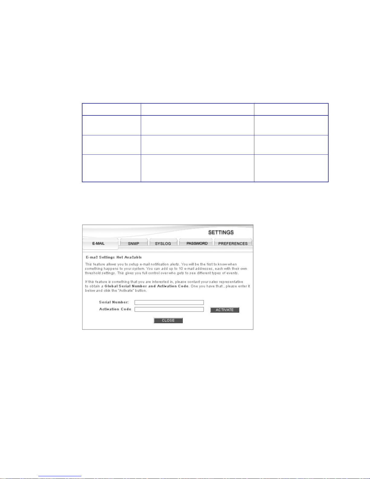
If a remote login is attempted from another host system on the same network and you do not have a
global license, you will see a message displayed regarding this. You will have the option to upgrade your
license by entering your serial number and activation code. You can also upgrade your license from the
Other Servers section by clicking on the link in the notice displayed or the upgrade can be accessed by
clicking the Settings button (E-MAIL tab, default, presents an upgrade option when using a local or
remote access license).
Note Refer to your disc envelope to obtain the serial number and activation code.
1 Click on the “link” provided under “Other Servers.” The Settings window will open with the E-MAIL tab
selected. There you will enter the required information and click the Activate button.
2 Once you have completed the upgrade, the window will reload with the E-MAIL, SYSLOG, and SNMP
tabs active. Click on the CLOSE button in the confirmation window.
3 Click the CLOSE button on the Settings window.
4 You can verify the change by clicking the About button and noting that it now displays (Global), see
12.5.1 ”About” beginning on page 135.
Also the notice displayed under the Other Servers section will now be removed and any remote
discovered StorView Servers will be displayed.
License Features Version
Local Access Configuration, GUI Monitoring, and Event
Logs.
Host-based
Remote Access All the features of Local, plus Remote Login
and Monitoring Failover.
Embedded
Global Access All the features of Local and Remote, plus
E-Mail, SNMP, SYSLOG, and Other Servers
list.
Host-based and Embedded
Figure 4–1 License Upgrade Screen
Page 37
Getting Started
29
4.3 E-MAIL
4.3.1 Configuring E-Mail Notices
With a Global license installed, StorView provides you with the ability to establish up to ten E-Mail
addresses where notices of events can be automatically sent.
To configure the E-Mail notifications perform the following:
1 From the Main screen click the SETTINGS button.
The Settings window will open with the E-MAIL tab selected.
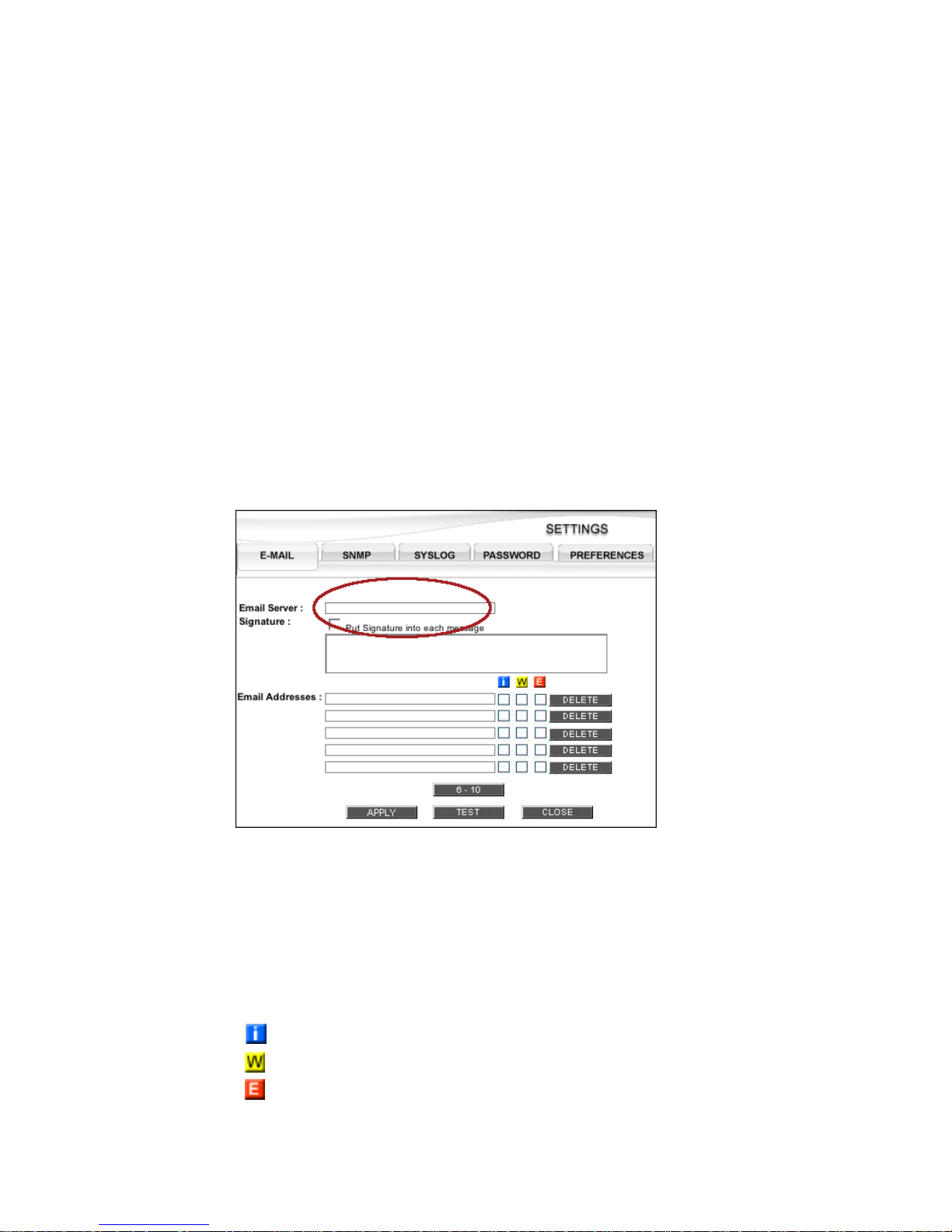
2 Enter the “name” or “IP address” of your E-Mail server.
This will be the SMTP mail server name. E-Mail messages are sent to the E-Mail server using port 25. If
your E-Mail server is not configured to receive on port 25, then E-Mail will not function properly.
3 If you would like a signature appended to the message, click the check box and type in the signature
information in the scrollable window provided.
4 Enter the user E-Mail addresses. You may add up to ten (10) E-Mail addresses.
Type the full E-Mail address, and click one or more of the check boxes for the type of event to which the
user is to be notified. The types of events are: Information, Warning, and/or Error.
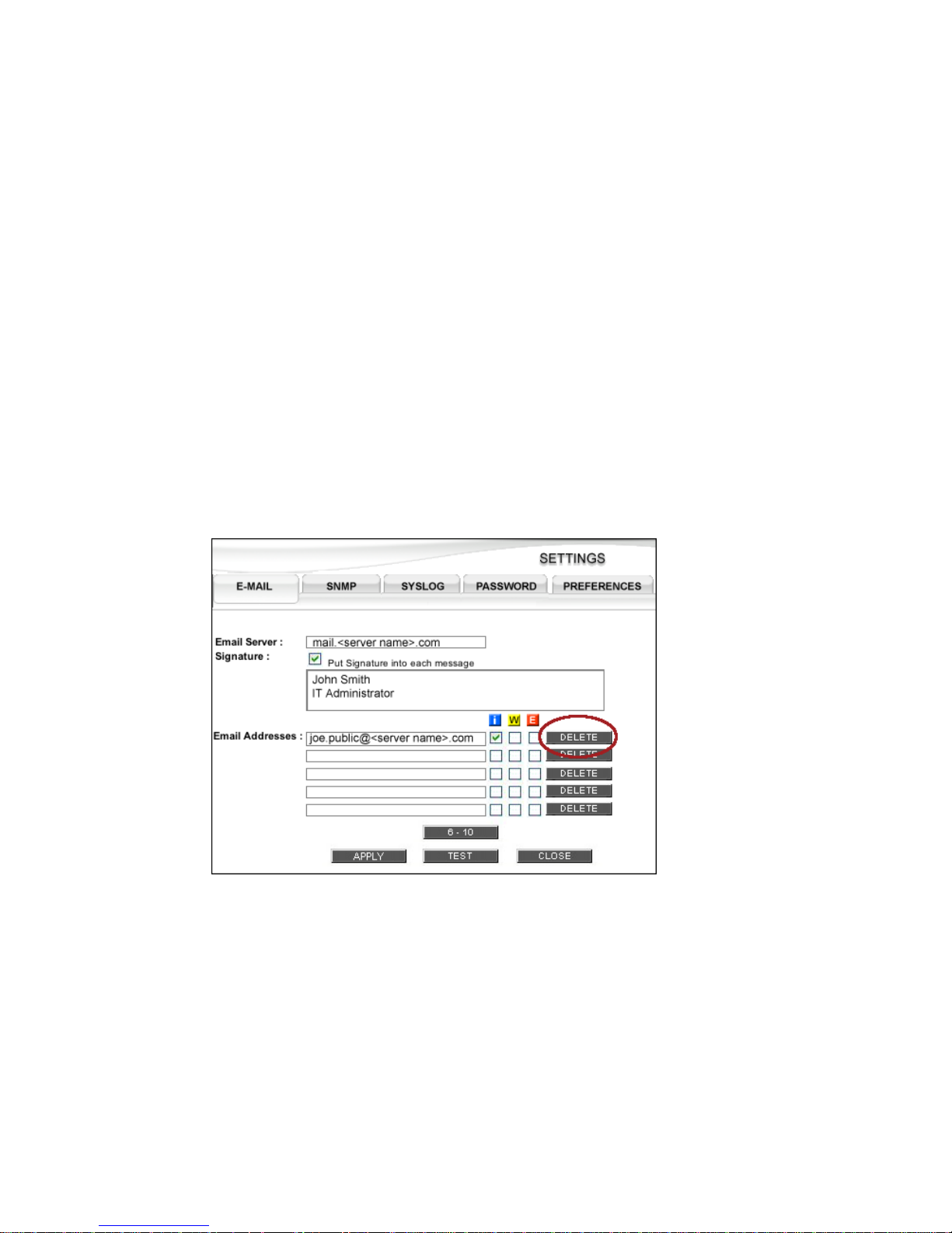
Figure 4–2 Settings Screen - E-MAIL Tab
Information
Warning
Error
Page 38
StorView RAID Module
30
If you have more than five E-Mail recipients, you will need to click the button “6 - 10” to access the next
five address blocks.
5 Once complete, click the APPLY button.
You will receive a confirmation message that the changes were successfully completed. Click the CLOSE
button.
6 Test the configurations by clicking the TEST button.
You will receive a confirmation message that the test was successfully completed, and each addressee
will receive a “Test Message” from the mail server. Click the CLOSE button.
7 Click the CLOSE button on the SETTINGS window.
4.3.2 Deleting an E-Mail Addressee
1 From the Main screen click on the SETTINGS button. The SETTINGS window will open with the E-MAIL
tab selected.
2 Click the DELETE button next to the E-Mail Address name you wish to remove. The address is
immediately removed.
3 Click the APPLY button to make the changes effective and a status pop-up notice will appear. Click the
CLOSE button. Then click the CLOSE button on the SETTINGS window.
Figure 4–3 Settings Screen - E-MAIL Tab
Page 39
Getting Started
31
4.4 SNMP
4.4.1 Configuring SNMP Traps
StorView can be configured to send SNMP traps to any network management system. These traps carry
all the information that appears in the log entries for each level of severity.
Note If your system requires a MIB file, it is located in the following directory “C:\Program Files\StorView\alerts-
snmp.mib.”
All SNMP traps sent from StorView will be received by the host SNMP Servers designated in the settings
window for the specified port and community.
1 From the Main screen click on the SETTINGS button.
2 Click the SNMP tab.
3 Enter the SNMP Server name or IP address of the host you wish to receive SNMP traps.
4 Enter the IP port on which the SNMP Server expects to receive traps. The default is 162.
5 Enter the Community to which the traps belongs. The default is public.
SNMP Servers may belong to several different communities or receive packets for different communities.
6 Select the level of events you wish to be included in the traps. You can select from Information, Warning
and Error types. For more information, see ”Event Logs” beginning on page 143.
7 Click the APPLY button.
8 Test the configurations by clicking the TEST button.
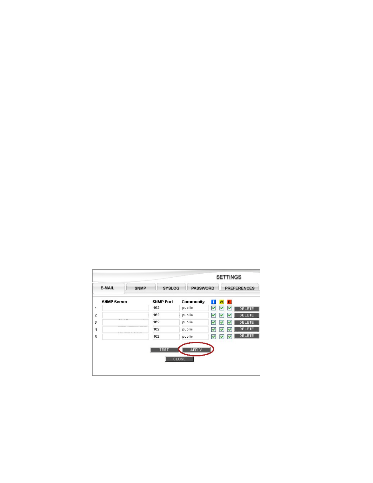
Figure 4–4 Settings Screen - SNMP Tab
Page 40

StorView RAID Module
32
You will receive a confirmation message that the test was successfully completed, and each addressee
will receive a “Test Message.” Click the CLOSE button.
9 Click the CLOSE button on the SETTINGS window.
4.4.2 Deleting an SNMP Server
1 From the Main screen click on the SETTINGS button.
2 Click the SNMP tab.
3 Click the DELETE button next to the SNMP Server you wish to remove. The server is immediately
removed.
4 Click the APPLY button to make the changes effective and a status pop-up notice will appear. Click the
CLOSE button. Then click the CLOSE button on the SETTINGS window.
Page 41

Getting Started
33
4.5 SYSLOG
StorView’s SYSLOG agent is a module designed for StorView that enables sending RAID system event
logs to all listening SYSLOG clients on all installed platforms.
SYSLOG requires that the Global Access license be enabled before the feature is activated. Once
activated on each installation of StorView, the locally monitored storage system events are then sent to
the SYSLOG daemon running on the host system.
StorView SYSLOG is designed for greater flexibility in that it supports “many-to-many” mapping. You may
have:
• Multiple SYSLOG servers that monitor a single RAID storage system for event logs.
• A single SYSLOG server that monitors multiple RAID storage systems for event logs.
• Multiple SYSLOG servers that monitor multiple RAID storage systems for event logs.
This “many-to-many” mapping provides an additional safety net in that it offers data redundancy. In this
instance a failed SYSLOG server will not have any impact if another SYSLOG server is functioning
normally.
If you are using a Linux operating system, the syslogd daemon is a component of your operating system.
If you are using a Windows operating system you will need to install a separate tool (http://syslogwin32.sourceforge.net/) which runs as a Windows service.
4.5.1 Gathering Logs
A host based StorView running the SYSLOG agent with two in-band connections to RAID storage
systems, each with a unique WWN ID. Assuming the SYSLOG is configured to log/dispatch Error type
events, It will gather all Error type events for both RAID storage systems and sent them directly to the
intended host.
The StorView SYSLOG agent is global in scope, in that it will always receive all error logs from the
accessible storage systems. It is not possible to customize filtering of events for each managed storage
system for that host.
With Embedded StorView, previously configured listening SYSLOG servers will persist even though the
embedded module is flashed with new software as the file data is stored in NVRAM and is not affected
by software upgrades.
However, with instances of installed host-based StorView, you must backup or make a copy of the
syslog.ini file otherwise software updates will destroy the configuration information.
4.5.2 SYSLOG Daemon
The daemon listens for incoming event log messages on port 514. It logs them to a messages file. The
SYSLOG messages consist of:
• Facility - indicates the type of syslog message. For example they can be kernel, user level, mail
system and system daemon messages.
• Priority - indicates the sensitivity of the message, to include: Information, Warning, or Error.
• Timestamp - indicates the date and time of the event.
Page 42
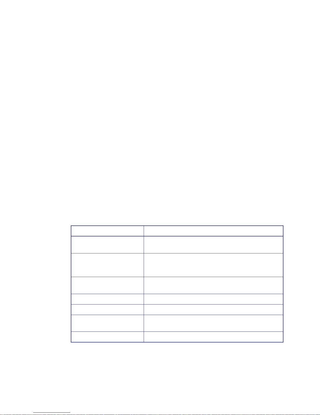
StorView RAID Module
34
• Originating Device - specifies which device originated the event message.
• Message Content - provides a plain language content of the event message.
SYSLOG daemon supports both Linux and Windows platforms.
4.5.3 Operational View
Whenever a new RAID storage system event is logged, based on the type of event, StorView SYSLOG
will sent the message out to all its subscribers that match the type of event involved. If the event was an
Error message type, and all daemons are configured to receive those type of event messages, then they
all will receive the event log. If the event was an Information message type, then only those daemons
configured to subscribe to Information priority message will receive the event log.
Event logs are sent in standard text format and have no encryption, in such security can be a concern.
Additionally UDP packets are involved so there is no assurance that the event log arrived at the
subscriber (SYSLOG server).
4.5.4 Configuring SYSLOG
1 If you have not yet enabled the Global Access license please do so at this time, see 4.2 ”Upgrading the
Access License” beginning on page 27.
After activating the Access license, you will see the following screen when the SYSLOG tab is selected.
The following fields are described:
2 Enter the IP addresses of the host servers designated to be SYSLOG servers.
3 Enter the port ID of the recipient SYSLOG server. You must enter a correct value otherwise you will
receive an error message.
Field Description
SYSLOG Server Allows the user to enter the IP address of the SYSLOG servers. An
error message is displayed if an invalid server name is entered.
SYSLOGD Port Allows the user to enter a specified SYSLOG port. The default port
is 514. An error message will appear if the enter is invalid or left
blank. The range of port IDs are: 1 - 65535.
Information (I) If checked the recipient would receive Informational type of event
logs.
Warning (W) If checked the recipient would receive Warning type of event logs.
Error (E) If checked the recipient would receive Error type of event logs.
Delete Button Clicking this button clears the previously entered IP address for the
selected line and resets the check boxes to their default state.
Test Button Send out a dummy test message to the specified recipient servers.
Page 43
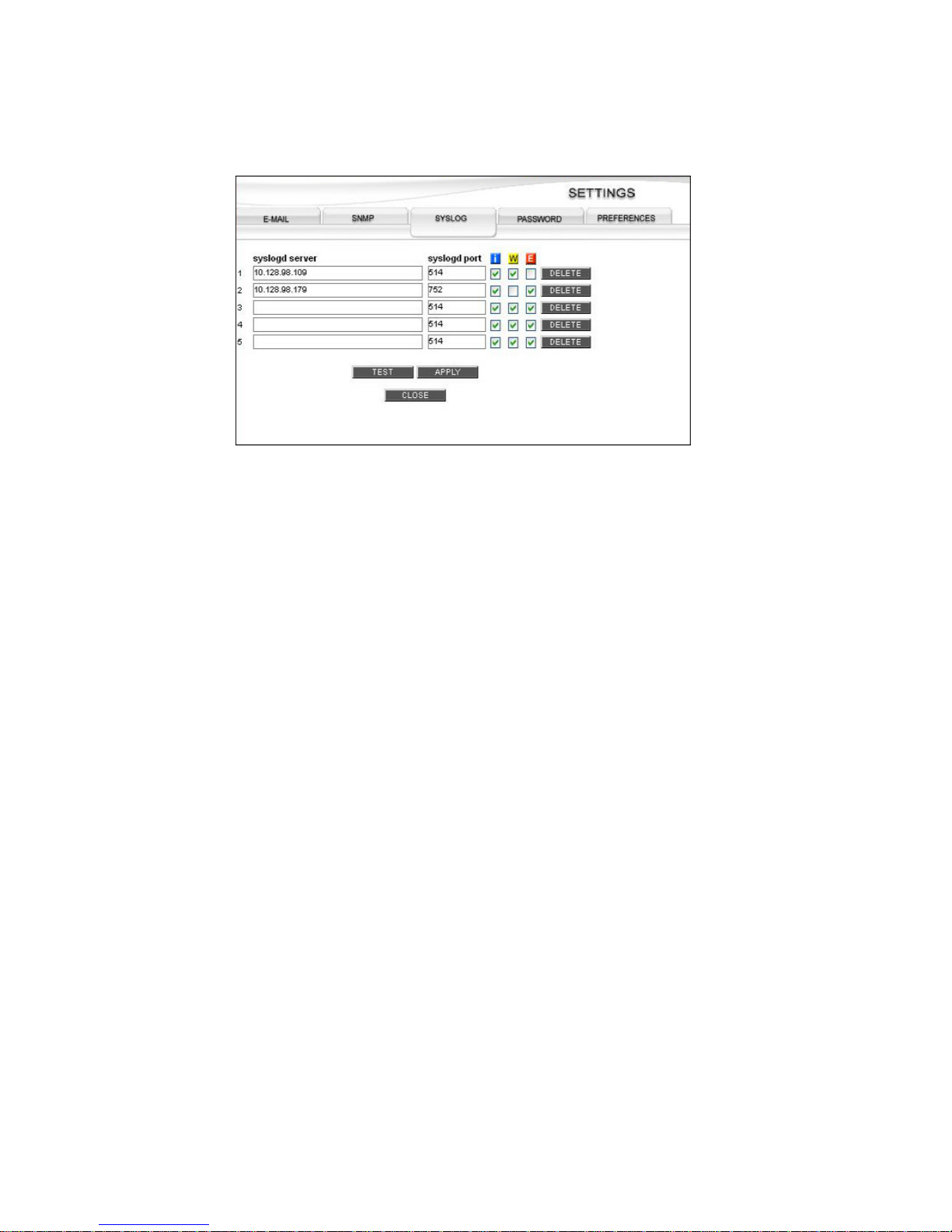
Getting Started
35
4 Select the check boxes under the severity/priority icons.
5 Click the APPLY button to save your settings.
6 If you are finished completing the setup, click the CLOSE button on the SETTINGS window.
7 If you wish, test the settings by clicking the TEST button.
You will receive a confirmation message that the test was successfully completed, and each SYSLOG
server will receive a “Test Message.” Click the CLOSE button.
4.5.5 Delete a SYSLOG Server
1 Access the Settings window and select the SYSLOG tab.
2 Click the DELETE button next to the “syslogd server” you wish to remove. The server name is
immediately removed.
3 Click the APPLY button to make the changes effective and a status pop-up notice will appear. Click the
CLOSE button. Then click the CLOSE button on the SETTINGS window.
Figure 4–5 Settings Screen - SYSLOG Tab
Page 44
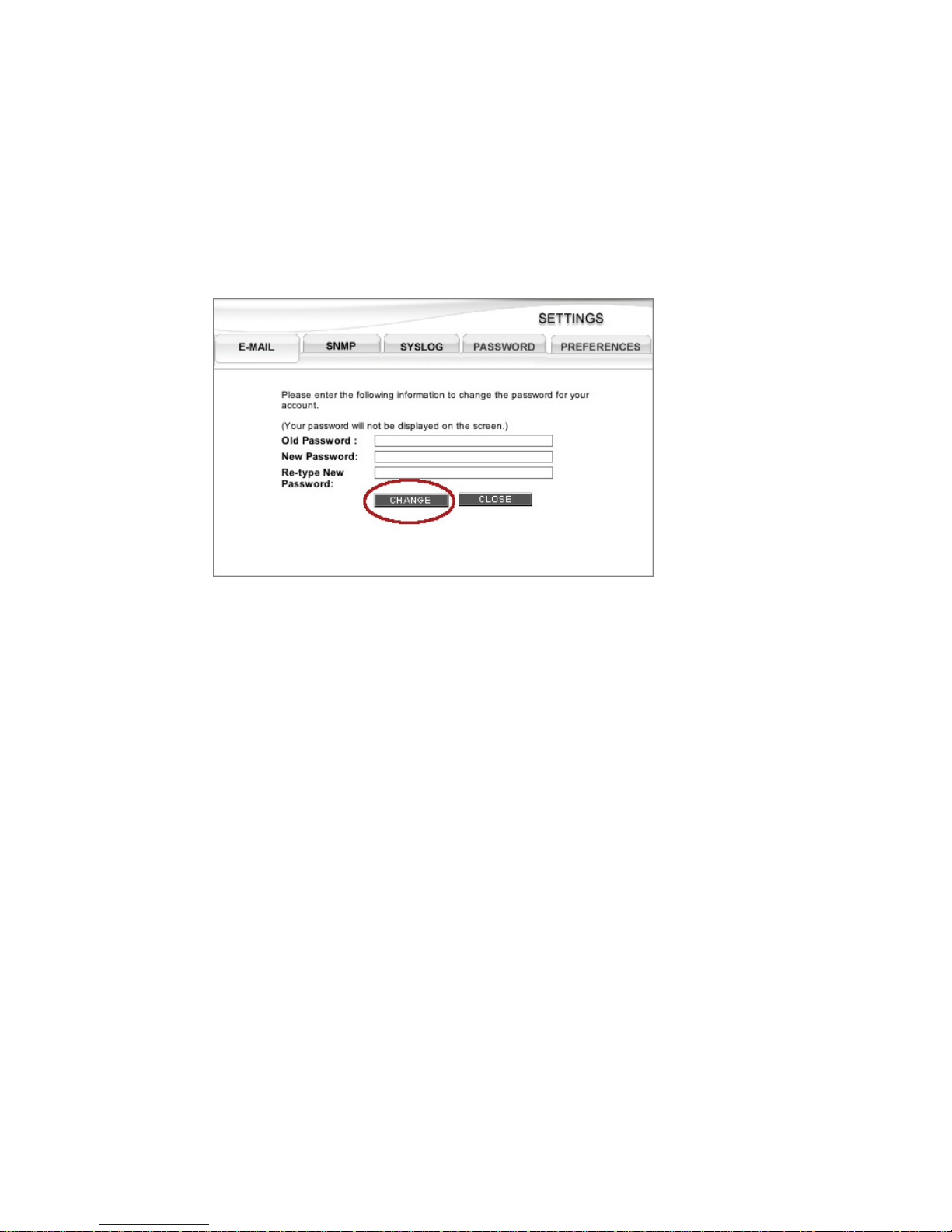
StorView RAID Module
36
4.6 Changing the Password
This option provides the ability to change the access password used at log in.
1 From the Main screen click on the SETTINGS button.
2 Click the PASSWORD tab at the top of the window.
Note Passwords will not be displayed as you type them.
3 Type in the Old Password and press the <Tab> key or click in the next text box.
4 Type in the New Password and press the <Tab> key or click in the next text box.
5 Re-type the New Password and click the CHANGE button.
You will receive a confirmation message that the changes were successful. Click the CLOSE button.
6 Click the CLOSE button on the SETTINGS window.
Note If you lose or misplace your password, contact technical support for further instructions.
Figure 4–6 Settings Screen - Password Tab
Page 45

Getting Started
37
4.7 Monitoring Settings
The following options enable network administrators to make adjustments to the StorView server’s
multicast functionality. In the event there is a port conflict with the default multicast port, you have the
ability to change this parameter.
Note The Monitoring Settings are disabled with the Remote license, you must upgrade to a Global license to
enable these features.
1 From the Main screen click on the SETTINGS button, then click the PREFERENCES tab.
2 Click the pull-down menu for “Select Monitoring Group” and choose Group 1, Group 2, or Group 3. Group
1 is port 9191, Group 2 is port 9192, and Group 3 is port 9193.
3 Click the APPLY button to make the changes effective, then click the CLOSE button. Click the CLOSE
button on the SETTINGS window.
Figure 4–7 Monitoring Settings Screen - Preferences Tab (Host-based Version)
Figure 4–8 Monitoring Settings Screen - Preferences Tab (Embedded Version)
Page 46
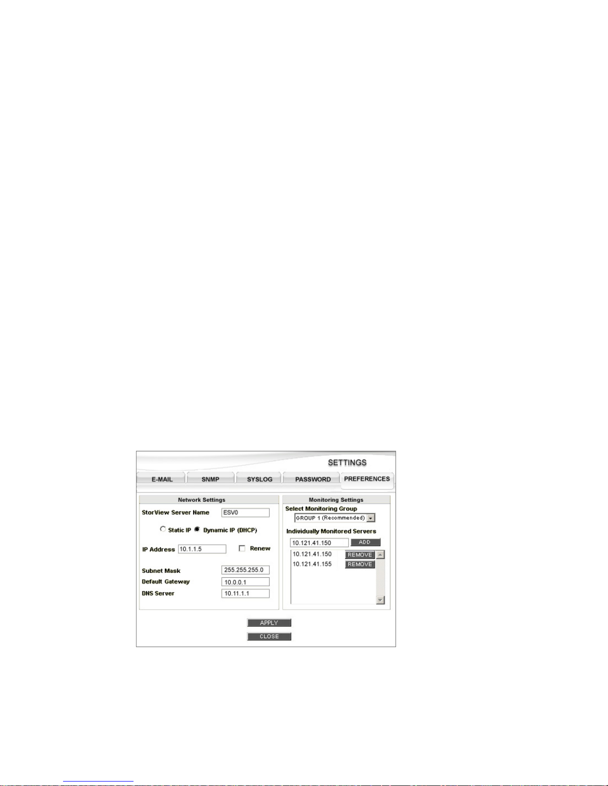
StorView RAID Module
38
4.7.1 Additional Monitoring Servers
To specify additional StorView server(s) on a different subnet to be included in the receipt of StorView
server packets, enter the IP addresses of those other StorView servers. You may add up to 10 additional
monitored servers.
1 From the Main screen click on the SETTINGS button.
2 Click the PREFERENCES tab at the top of the window.
3 Enter the IP address in the “Individually Monitored Servers” field of another StorView server outside the
subnet and click the ADD button.
4 Add additional explicit IP addresses of any other StorView server you wish to include to receive packets
that is outside the subnet and click ADD button. Otherwise, skip to step 5.
5 Click the APPLY button.
6 Click the CLOSE button on the SETTINGS window.
4.7.2 Remove Monitored StorView Server IP
1 From the Main screen click on the SETTINGS button.
2 Click the PREFERENCES tab at the top of the window.
3 Under the Individually Monitored Servers section, select the Server IP Address you wish to delete and
click the REMOVE button.
4 Click the APPLY button. A confirmation window will appear, click the CLOSE button.
5 Click the CLOSE button on the SETTINGS window.
Figure 4–9 Settings Screen - Preferences Tab (Embedded Shown for Example Purposes)
Page 47
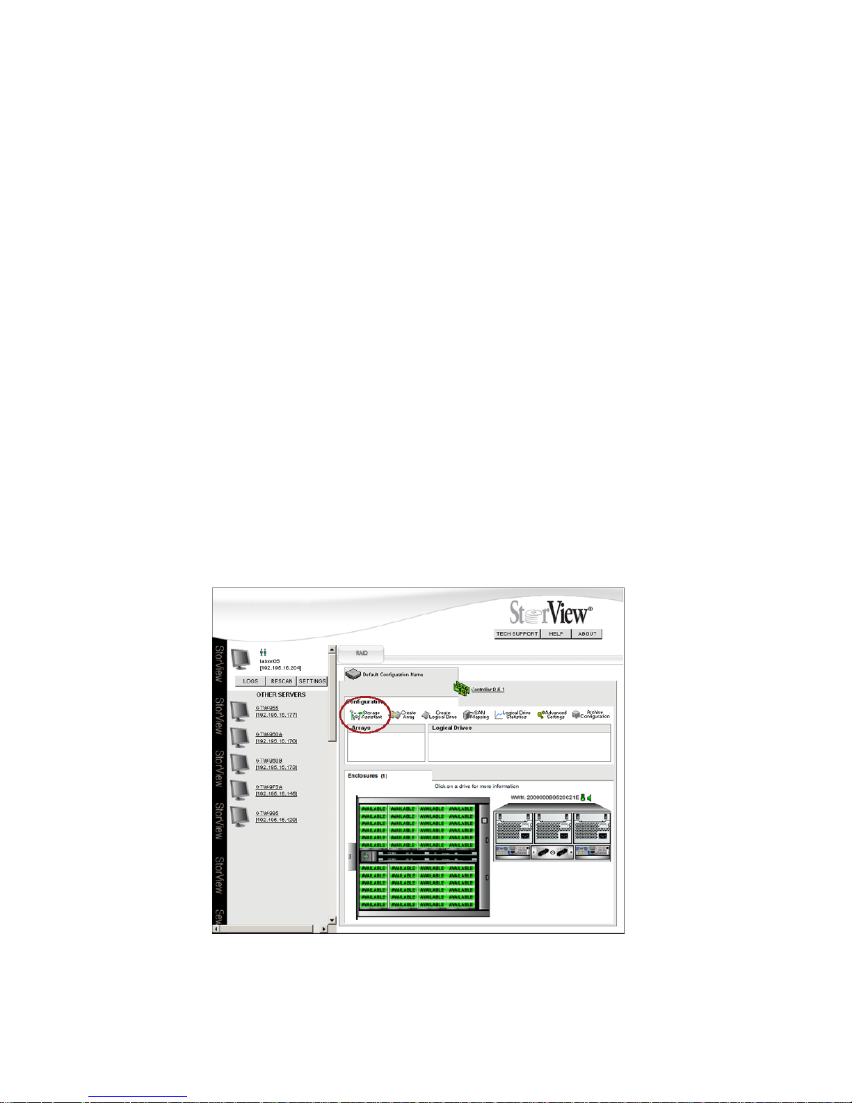
Storage Assistance
39
Chapter 5
Storage Assistant
5.1 Assisted Automatic Configuration
Note If you will be manually configuring your disk array, hot spare drives and logical drives, skip this chapter.
The StorView Storage Assistant is a wizard like feature that will automatically configure your storage
system after it has obtained some brief information from the user.
1 To begin, click the Storage Assistant icon on the Tool Bar located on the Main screen.
2 On the Introduction page enter a name for the Configuration.
Figure 5–1 Main Screen - Starting Storage Assistant (RS-4835-F4-5404E Shown)
Page 48
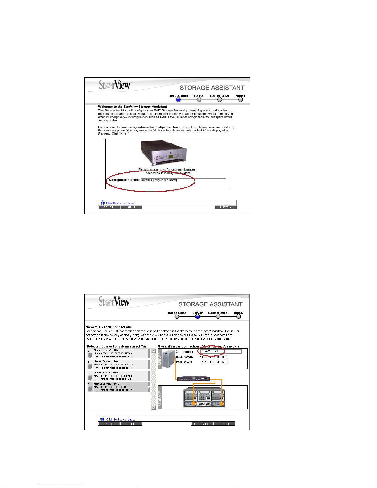
StorView RAID Module
40
The name is used to identify this storage solution. You may use up to 64 characters, although only the
first 25 characters are displayed.
3 Click the NEXT button.
Note At any point you can click the “PREVIOUS” button to move back one screen and make any necessary
changes.
4 Select a host server connection for this storage from the list of detected connections. Enter a name for
this server connection and click NEXT. Enter a name for the logical drive or use the default name.
Figure 5–2 Storage Assistant - Introduction (RS-4835-F4-5404E Shown)
Figure 5–3 Storage Assistant - Server Screen (RS-4835-F4-5404E Shown)
Page 49
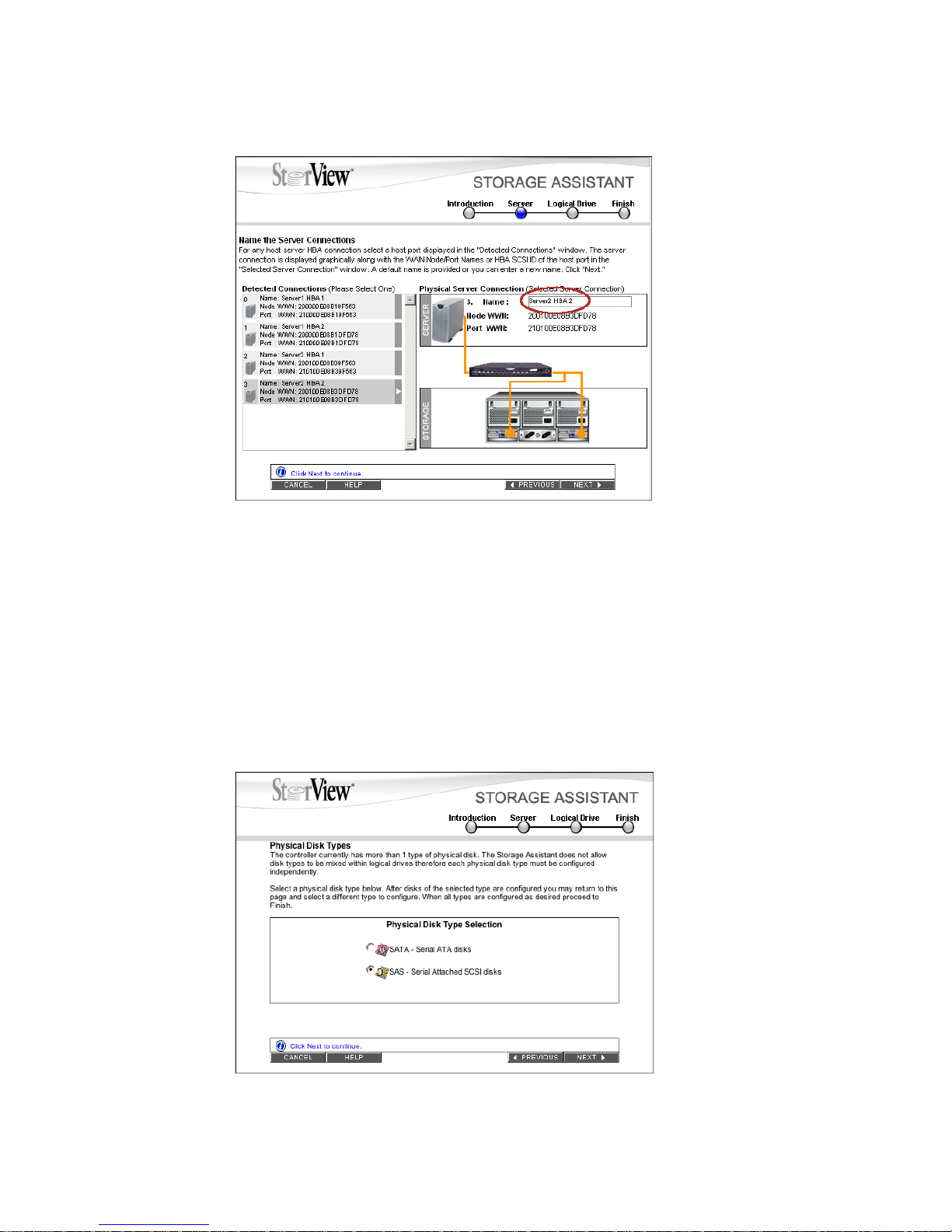
Storage Assistance
41
5 (RS-1220-F4-5402E, RS-1220-F4-5412E, RS-1220-E3-5402E, and RS-1220-E3-5412E Only) Click the
NEXT button. If you have mixed SAS and SATA disk drives in your enclosure, the following screen will
appear. If you do not have mixed drives proceed to the Server page, skip to step 6.
Note: You cannot mix SAS and SATA drive types. You must create the logical drives from array’s
comprised of the same type of drives then return back to this page and select the other drive
type and create additional logical drive.
Note: (RS-1220-F4-5412E and RS-1220-E3-5412E Only) You cannot mix SATA MUX Transition
card types in the same array. You must choose all SATA drives with A/A MUX Transition
cards or A/P MUX Transition cards.
Figure 5–4 Storage Assistant - Server Screen (RS-1220-F4-5404E Shown)
Figure 5–5 Storage Assistant - Physical Disk Type Screen
Page 50
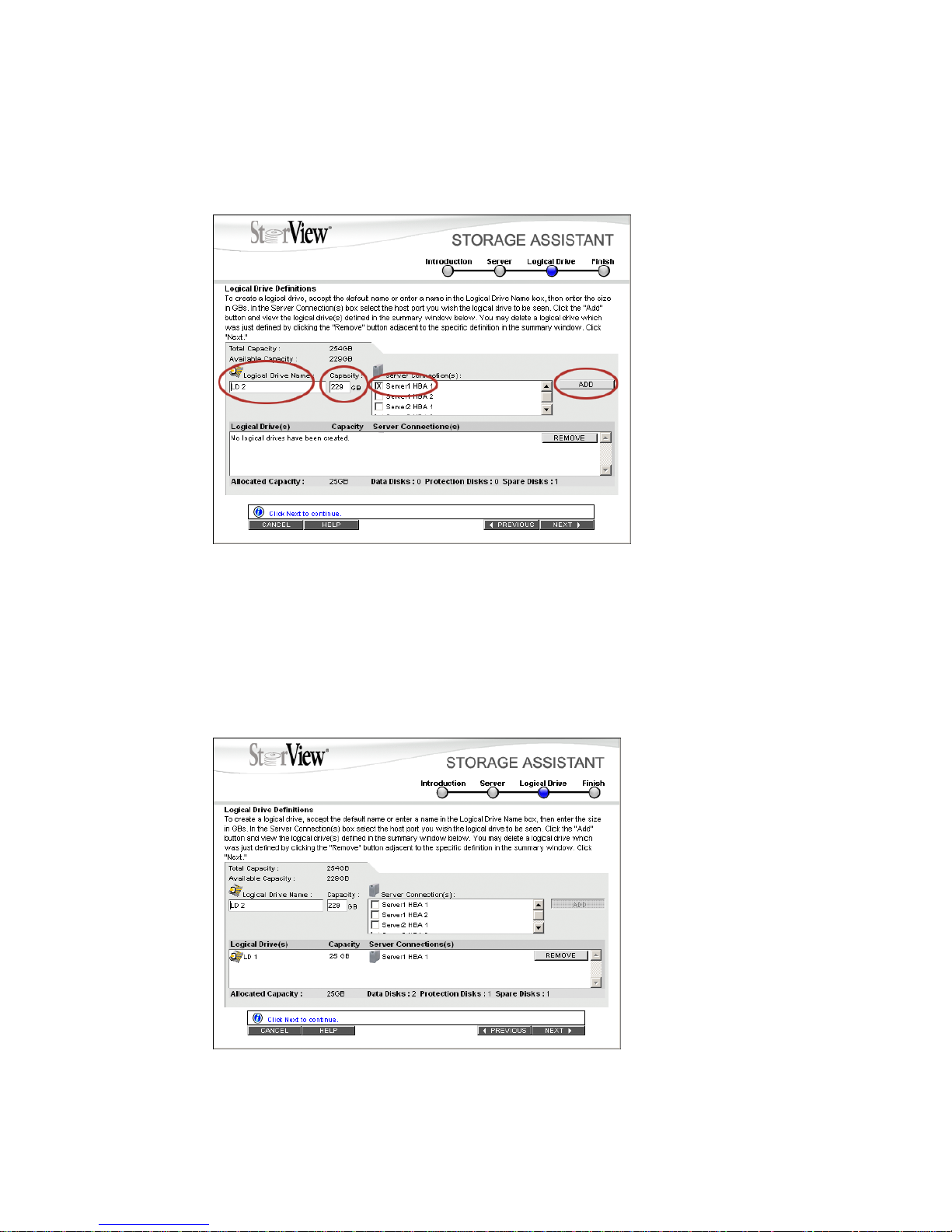
StorView RAID Module
42
After you have selected a specific drive type and created the logical drive(s) with those disks, you can
then click the PREVIOUS button to create another logical drive using the drive type not yet selected.
Or, you can alternate back and forth between selecting a disk type and creating logical drive(s).
6 Enter the capacity for the logical drive (GB’s), or you may use the default capacity. The value is expressed
in GBs.
7 Click the check box next to the named server connection(s) displayed in the Server Connection(s) pane.
Click the ADD button. The Logical Drive is added to the summary window at the lower section of the
window.
Note Repeat steps 4 - 6 for each additional Logical Drive you wish to create and assign to a server.
Figure 5–6 Storage Assistant - Logical Drive Screen
Figure 5–7 Storage Assistant - Logical Drive Screen
Page 51

Storage Assistance
43
If you decide that a Logical Drive you added is not desired, you may remove it from the list by clicking the
REMOVE button next to the Logical Drive name in the Configuration Summary window.
If you have used up all the available capacity, the fields will gray out and the available capacity will display
“0 GB” in red.
8 You are presented with a summary of your selections. Click the APPLY button.
The Storage Assistant will begin configuring the storage solution.
Figure 5–8 Storage Assistant - Logical Drive Screen
Figure 5–9 Storage Assistant - Finished Screen
Page 52

StorView RAID Module
44
This completes the configuration of your storage solution. Before you bring the storage system online and
into service, we recommend that a backup copy of the configuration be made, see 6.6 ”Saving the
Configuration” beginning on page 65.
Page 53

Configuring a Storage Solution
45
Chapter 6
Configuring a Storage
Solution
6.1 Creating Disk Arrays
Configuring a storage solution requires some planning to ensure that you define the correct RAID level
and array options, hot spares and logical drives for your solution requirements.
This chapter will step you through the process to configure and manage your disk arrays, assign hot
spares and create the logical drives. You should have a basic understanding of RAID concepts.
6.1.1 RAID Levels
The following are the drive requirements for each supported RAID level.
Table 6–1 Drive Requirements by RAID Level
RAID Level Minimum No. of Drives Maximum No. of Drives
0116
1216
5316
6* 6 16
50 6 16
10 4 16
* RAID 6 supports only the following drive configurations: 6 (4 data drives + 2 parity drives), 11
(9 data drives + 2 parity drives), 12 (10 data drives + 2 parity drives), and 16 (14 data drives
+ 2 parity drives).
Page 54

StorView RAID Module
46
6.1.2 Terminology
The following describes some of the terminology used when creating disk array’s and logical drives.
Term Description
Array A group of disk drives that are combined together to create a single
large storage area. Up to 64 arrays are supported, each containing up
to 16 drives per array. There is no capacity limit for the arrays.
Back-off Percent In order to allow drives from a different family or manufacturer to be
used as a replacement for a drive in an array, it is recommended that
a small percentage of the drive’s capacity be reserved when creating
the array. This is user selectable, from 0 to 10 percent. This is
sometimes known as Reserved Capacity.
Cache Flush Array This is the array that is used to automatically flush cache data in a
situation where power has failed to some of the drives.
Chunk Size This is the amount of data that is written on a single drive before the
controller moves to the next drive in the stripe.
Initialization RAID 5, 6, and 50 disk arrays must have consistent parity before they
can be used to protect data. However, StorView will initialize all array
RAID types regardless. If the user chooses the Trust option during
array creation or stops the initialization, the array will be trusted. Note
that any drive failure in a trusted array will result in data corruption.
It is possible to perform the initialization later. This recalculates the
parity based on current data, ensuring data and parity are consistent.
Logical Drive Availability To accommodate hosts with multiple ports and multiple host systems,
it is possible to restrict a logical drive’s availability to a particular HBA
or controller port. Access can be enabled or disabled for each host port
of each controller.
Mapped LUN Number Each logical drive is presented to the host system with a unique LUN.
In certain cases (such as after deleting another logical drive) it may be
desirable to change the number that a logical drive is presented as.
This can be done at any time, bearing in mind that any attached host
systems may need to be rebooted or re-configured to maintain access
to the logical drive.
RAID Level 0 RAID 0 is defined as disk striping where data is striped or spread
across one or more drives in parallel. RAID 0 is ideal for environments
in which performance (read and write) is more important than fault
tolerance or you need the maximum amount of available drive capacity
in one volume. Drive parallelism increases throughput because all
disks in the stripe set work together on every I/O operation. For
greatest efficiency, all drives in the stripe set must be the same
capacity. Because all drives are used in every operation, RAID 0 allows
for single-threaded I/O only (i.e., one I/O operation at a time).
Environments with many small simultaneous transactions (e.g., order
entry systems) will not get the best possible throughput.
Page 55

Configuring a Storage Solution
47
RAID Level 1 RAID 1 is defined as disk mirroring where one drive is an exact copy of
the other. RAID 1 is useful for building a fault-tolerant system or data
volume, providing excellent availability without sacrificing
performance. However, you lose 50 percent of the assigned disk
capacity. Read performance is somewhat higher than write
performance.
RAID Level 5 RAID 5 is defined as disk striping with parity where the parity data is
distributed across all drives in the volume. Normal data and parity data
are written to drives in the stripe set in a round-robin algorithm. RAID 5
is multi-threaded for both reads and writes because both normal data
and parity data are distributed round-robin. This is one reason why
RAID 5 offers better overall performance in server applications.
Random I/O benefits more from RAID 5 than does sequential I/O, and
writes take a performance hit because of the parity calculations. RAID
5 is ideal for database applications.
RAID Level 6 RAID-6 is the same as RAID-5 except that it uses a second level of
independently calculated and distributed parity information for
additional fault tolerance. This extra fault tolerance provides data
security in the event two drives fail before a drive can be
replaced. RAID-6 provides greater fault tolerance than RAID-5. There
is a loss in write performance with RAID-6 when compared to RAID-5
due to the requirement for storing parity twice for each write operation.
A RAID-6 configuration also requires N+2 drives to accommodate the
additional parity data, which makes RAID-6 require more raw
capacity than RAID-5 for an equivalent useable storage capacity.
RAID Level 10 RAID 10 is defined as mirrored stripe sets or also known as RAID 0+1.
You can build RAID 10 either directly through the RAID controller
(depending on the controller) or by combining software mirroring and
controller striping, or vice versa (called RAID 01).
RAID Level 50 This RAID level is a combination of RAID level 5 and RAID level 0.
Individual smaller RAID 5 arrays are striped, to give a single RAID 50
array. This can increase the performance by allowing the controller to
more efficiently cluster commands together. Fault tolerance is also
increased, as one drive can fail in each individual array.
Stripe The process of separating data for storage on more than one disk. For
example, bit striping stores bits 0 and 4 of all bytes on disk 1, bits 1 and
5 on disk 2, etc.
Stripe Size This is the number of data drives multiplied by the chunk size.
Sub-array In RAID 50 applications, this is the name given when individual RAID
5 arrays that are striped together. Each sub-array has one parity drive.
Unassigned Free Space The controller keeps a map of all the space that is not assigned to any
logical drive. This space is available for creation or expansion. Each
unassigned region is individually listed.
Term Description
Page 56
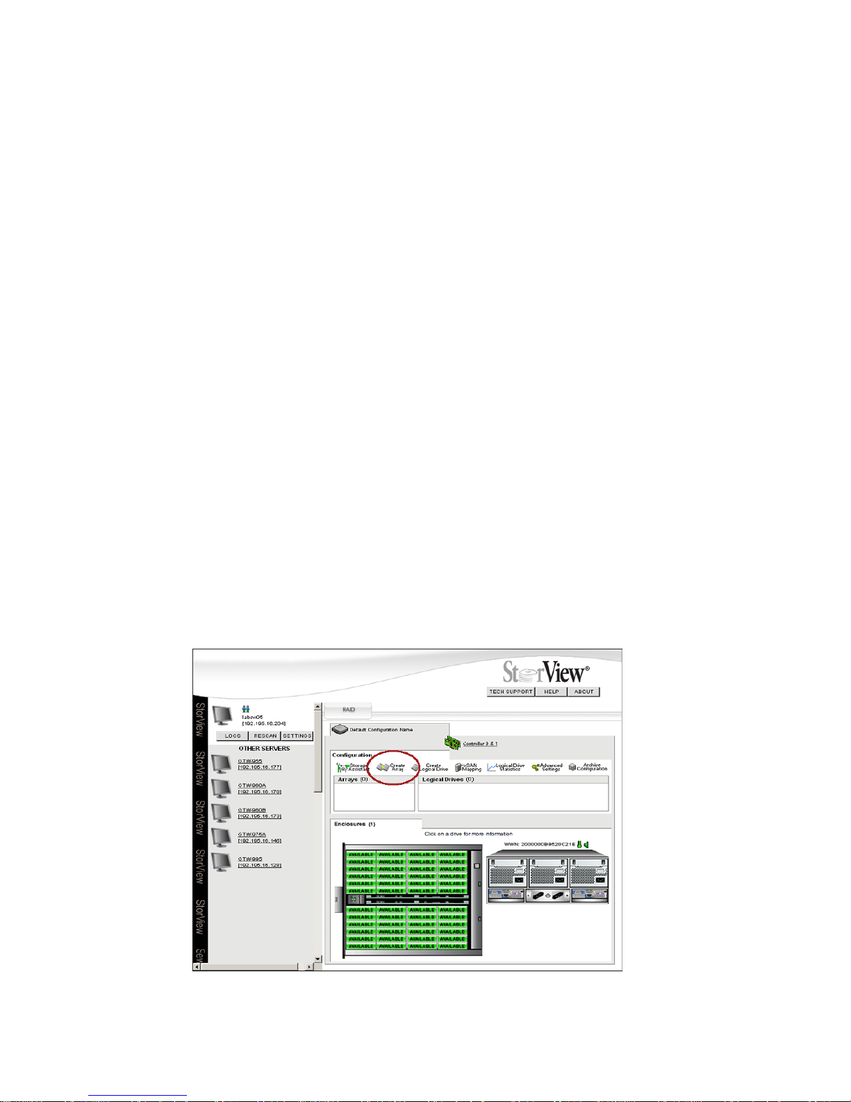
StorView RAID Module
48
6.1.3 Optimization and Drive Selection for RAID 5 and 6
Typical RAID 5 or 6 implementations require a number of steps to write the data to the drives. In order to
optimize your system performance based on the type of writes you expect in your operation, we have
provided detailed information on optimizing the performance using full strip write operations in an
appendix. If you intend to setup a RAID 5 or 6 disk array and wish to consider optimum performance, you
will need to consider the number of data drives, parity drives, and chunk size. For a review, see
”Optimizing Write Performance” beginning on page 185. Additional information is provided at the
appropriate step during configuration.
6.2 Create the Array
Configuring an array involves a few steps from one window, the Create Array window. From this window,
disk drives are selected then the parameters for the array are set through drop-down menu selections or
check boxes. The parameters define the details of the array and are saved in the configuration file.
The configuration file is stored on all disk drives that are members of the array (regardless of whether the
drives are in multiple enclosures). No changes are made to the configuration until the current process is
saved, so it is possible to quit at any time without affecting the current configuration.
After making changes to your configuration, be sure to make a new backup copy of the configuration file,
see 6.6 ”Saving the Configuration” beginning on page 65. The ability of making a backup copy of the
configuration allows you to quickly recover from a damaged configuration that was not self healing, and
restore everything to the point in time when the configuration was last saved. This preserves the definition
of the arrays, logical drives, Snapshots, SAN LUN Mappings and controller parameter settings.
Caution A damaged configuration could result in loss of data.
1 On the Tool Bar click the Create Array icon.
Figure 6–1 Main Screen (RS-4835-F4-5404E Shown)
Page 57
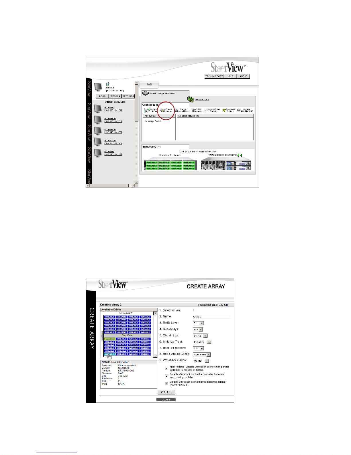
Configuring a Storage Solution
49
The Create Array window will open, see Figure 6–3 ”Create Array Window (RS-4835-F4-5404E Shown)”
beginning on page 49.
2 Select drives to include in your array. Click on each drive that has the “Available” icon displayed. The icon
will change to “Selected.”
As you select drives, the projected size of the array is displayed in the upper right corner of the window.
Note You will notice numbers next to each item on the screen. These are the suggested sequential steps to
follow when creating an array.
Figure 6–2 Main Screen (RS-1220-F4-5412E Shown)
Figure 6–3 Create Array Window (RS-4835-F4-5404E Shown)
Page 58
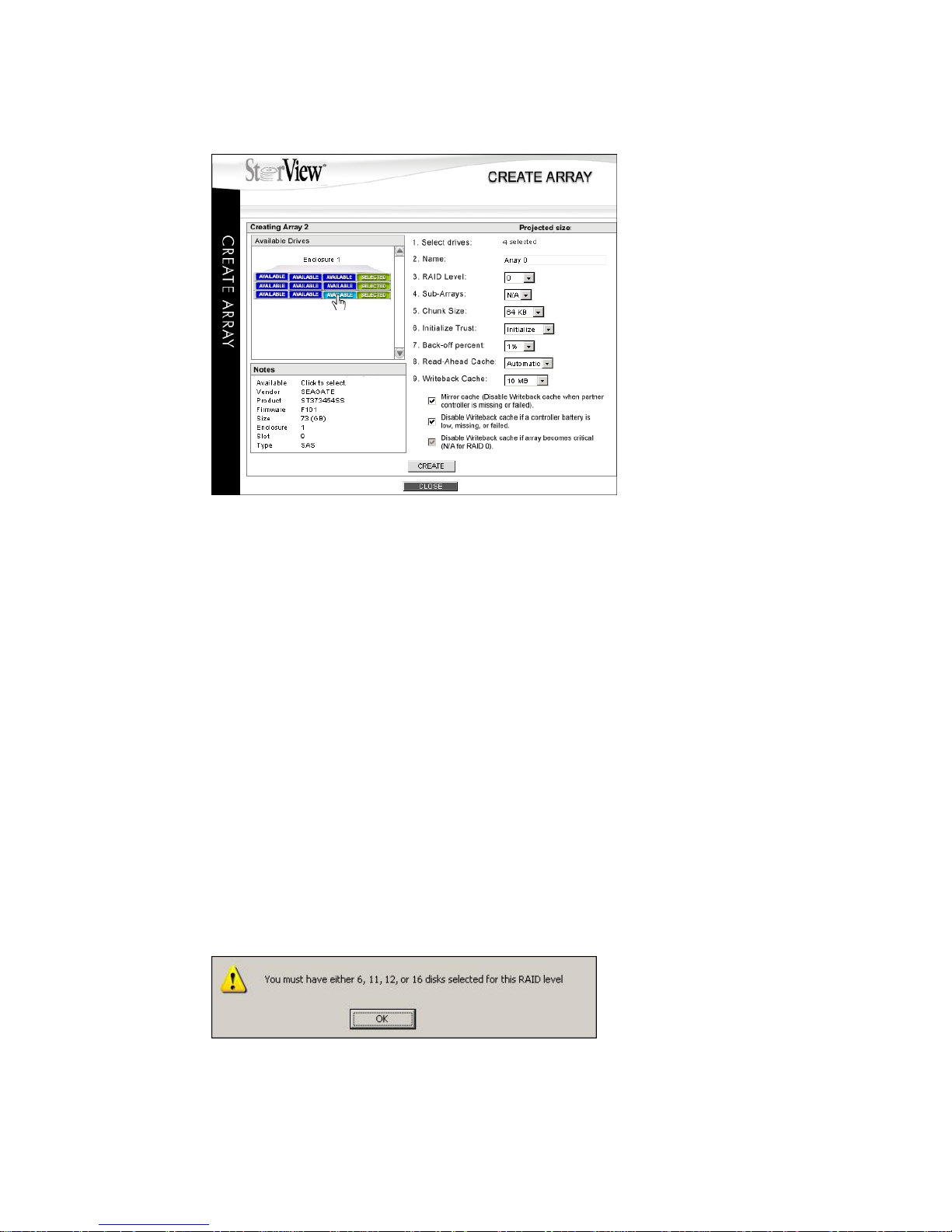
StorView RAID Module
50
3 Enter a name for your array. You may use up to 32 characters (ASCII).
4 Select the RAID level for the array.
Click the pull-down menu and choose from the available levels. These are based on the number of drives
selected, refer to the “Drive Requirements” table at the beginning of this chapter.
(For RAID 50 arrays.) Create the sub-arrays. From the pull-down menu select the number of subarrays you wish to create for this array. When you click the “Create” button you will get a warning if
you have selected more sub-arrays than allowed for the number of drives chosen. Reduce the
number of sub-arrays.
(For RAID 6) You must choose either 6, 11, 12, or 16 disk drives to enable the RAID 6 option.
Otherwise when the CREATE button is clicked a pop-up window with an error message is displayed
indicating that 6, 11, 12, and 16 drives are only supported for RAID 6. (Figure 6–5)
Note The Notes section under the Available Drives section will display information to help you with drive
selection. (Figure 6–6)
Note If you choose RAID Level 6 but the incorrect number of drives, you will see the following warning
message when you click the CREATE button. Click OK and choose the correct number of disk for the
particular RAID level.
Figure 6–4 Create Array Window (RS-1220-F4-5412E Shown)
Figure 6–5 RAID 6 Drive Selection Error
Page 59
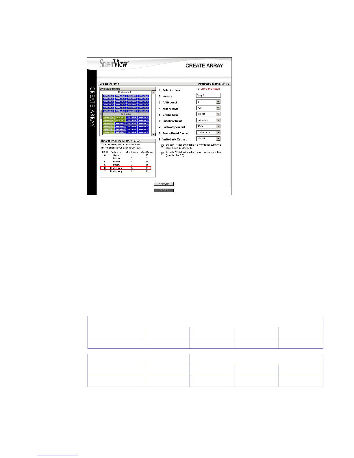
Configuring a Storage Solution
51
5 Choose the chunk size. Click the pull-down menu and select a chunk size (64K, 128K, or 256K).
Chunk size is the amount of data that is written on a single drive before the controller moves to the next
drive in the stripe.
For RAID level 0, 1, or 10, choose the correct size from the tables below. For RAID 5/50/6, refer to the
note below.
Note To achieve optimum RAID 5/50/6 write performance you should consider setting the chunk size based
on the specified number of drives for a Full Stripe Write when configuring RAID 5/50/6 arrays, for detailed
information see ”Optimizing Write Performance” beginning on page 185. For optimum performance, you
want to do as many full stripe writes as possible.
Note The controller firmware will automatically set the chunk size if a smaller chunk size is selected than the
value recommended for the number of drives and specified RAID level.
6 Select to Initialize the array. The default setting is to initialize, so you will just verify this setting. If it is not
set, click the pull-down menu and choose Initialize.
Figure 6–6 RAID 6 Drive Mismatch Condition (RS-4835-F4-5404E Shown)
RAID 0
Number of Drives 1234+
Minimum Chunk Size 256K 256K 128K 64K
RAID 1 & RAID 10 RAID 10 (0+1)
Number of Drives 2468+
Minimum Chunk Size 256K 256K 128K 64K
Page 60

StorView RAID Module
52
Initialization will begin automatically in the background once the array is created. You will have an option
to stop or pause the initialization from the Main screen. If you Stop an initialization, the array will be
trusted, see note below. As you create additional arrays, they too will begin initializing. The maximum
number of arrays that can be initialized in parallel is sixty-four (64).
Note The Trust Array option should only be used in very special circumstances, see 10.2.7 ”Trust an Array”
beginning on page 108.
7 Choose the “Back-off Percent” (reserved capacity) for the drives. The default is 1%.
This determines how much drive capacity to reserve for future capacity expansions or to enable
replacement drives of greater capacity sizes to be used.
Note The back-off percent option is not applicable to non-redundant array types. A RAID 0 array is a non-
redundant type of array and gains no benefit from establishing a reserve capacity.
8 Set the Read-Ahead Cache threshold.
The choices are automatic, disabled, and four pre-determined sizes (256KB, 512KB, 1 MB, and 2 MB).
Selecting Automatic, which is the recommended and default setting, allows the controller to determine
the optimum size. Selecting Disabled will turn off the Read-Ahead Cache. Select from one of the predetermined sizes to optimize the read performance based on your data patterns.
9 Set the Writeback Cache options.
Click the pull-down menu to select from Disabled, or choose one of the pre-determined cache threshold
sizes (1MB, 2MB, 4MB, 8MB, 16MB, 32MB, 64MB, 128MB, 256MB or MAX “MB”), see 6.2.1 ”Configuring
Array Writeback Cache” beginning on page 54.
There are three additional options to an active Writeback Cache: Mirror Cache (Disable Writeback Cache
when partner controller fails or is missing), Disable Writeback Cache if a controller battery is low or fails,
and Disable Writeback Cache if array becomes critical (N/A for RAID 0), (e.g., during a rebuild). Enable
the options for your application. For maximum data protection, it is recommended to enable all three
options when applicable.
The Writeback Cache is used to optimize the write performance specific to your data patterns. In general,
larger cache sizes will increase the write performance but may lower simultaneous read performance.
The recommended size is 16 MB. The strategy of write operations results in a completion signal being
sent to the host operating system as soon as the cache receives the data to be written. The disk drives
will receive the data at a more appropriate time in order to increase controller performance.
10 Click the CREATE button to complete this process.
11 You will see a confirmation message that the array was successfully created, click the CLOSE button.
12 Click the CLOSE button at the bottom of the Create Array window.
Page 61
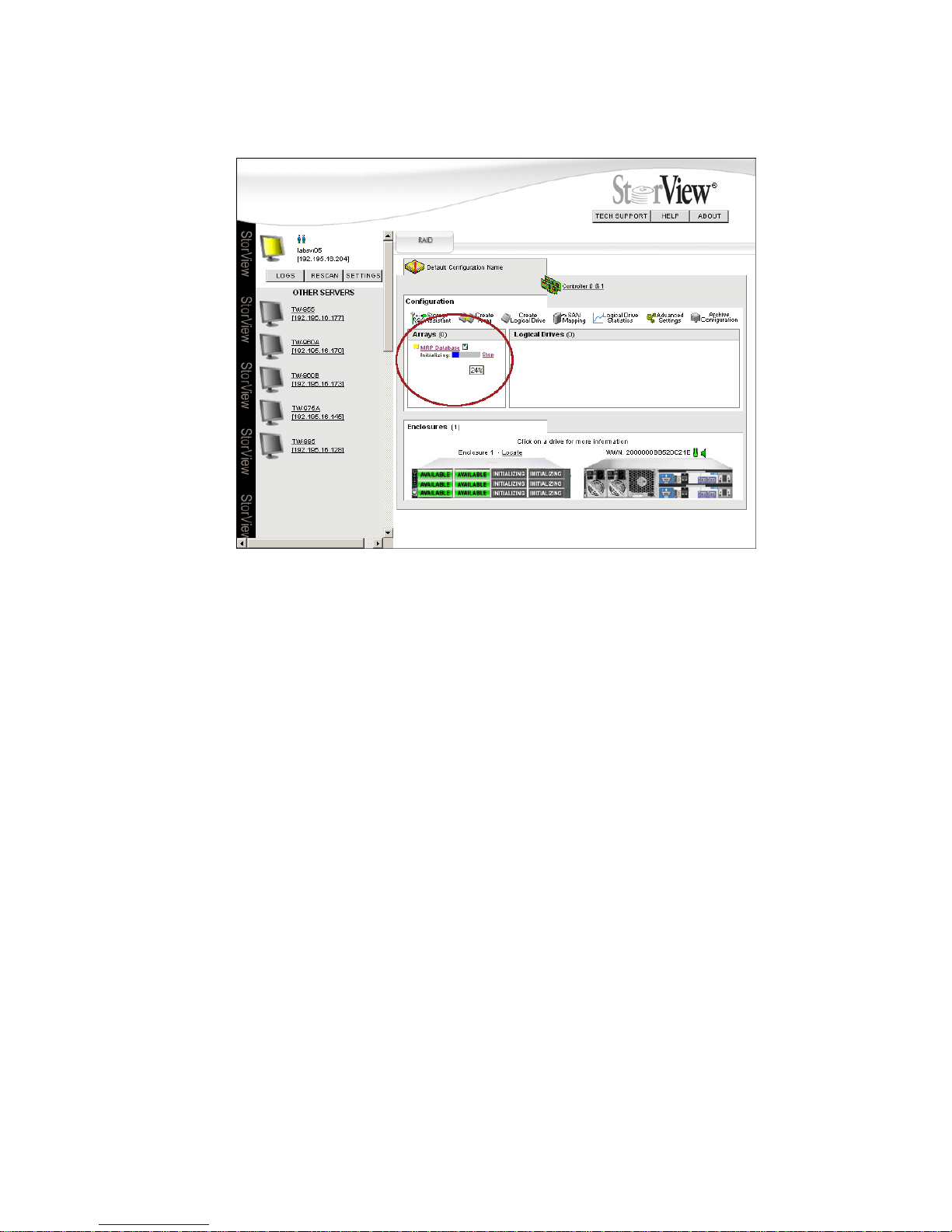
Configuring a Storage Solution
53
While monitoring the array initialization, under the Array name a progress bar appears displaying the
percent complete. Also, in the enclosure front view, the disk drives being initialized display an animated
icon indicating their present status.
You can stop or pause the Initialization process if you wish by clicking on the link located to the right of
the progress bar.
Stopping the initialization will cause your array to be trusted. If you stop the initialization, you want to
return at a later time, but before you being to use the array in a ‘live’ environment and initialize the array,
see 6.3 ”Initializing the Array” beginning on page 55.
Pausing the initialization will halt the process until the resume option is selected. You can change the
amount of processor time that is dedicated to the initialization for better initialization performance, see
9.2.2 ”Fault Tolerance” beginning on page 94.
Figure 6–7 Monitoring the Initialization Process at the Main Screen (RS-1220-F4-5412E Shown)
Page 62

StorView RAID Module
54
6.2.1 Configuring Array Writeback Cache
In a writeback cache operation, data is sent to the controller from the host and before actually sending
the data to the drives, the controller immediately responds to the host confirming the data was received
and written to the disk (even though the data may have not been written to the disk). The host may then
send more data. This can significantly increase performance for host systems that only send a low
number of commands at a time. The controller caches the data, and if more sequential data is sent from
the host, it can cluster the writes together to increase performance further. If sufficient data is sent to fill
a stripe in RAID 5, 6, and 50 configurations, the controller can perform a Full Stripe Write, which
significantly reduces the write overhead associated with RAID 5, 6, and 50.
Disabling writeback cache ensures that the data is sent to the drives before status is returned to the host.
With writeback cache enabled, if a short term power failure occurs, the battery back-up unit provides
adequate power to ensure that cache is written to disk when the power is restored.
In duplex operations, the cache is mirrored to both controllers which provides further redundancy in the
event of a single controller failure. Mirrored cache is designed for absolute data integrity. The cache in
each controller contains both primary cached data for the disk groups it owns, and a copy of the primary
data of the other controllers. Mirrored cache ensures that two copies of cache exist on both controllers
before confirming to the operating system that the write operation has completed.
Normally, write-intensive operations will benefit from the higher performance when writeback cache is
enabled on that array. Read-intensive operations, such as a streaming server, may not benefit from
writeback cache.
Page 63
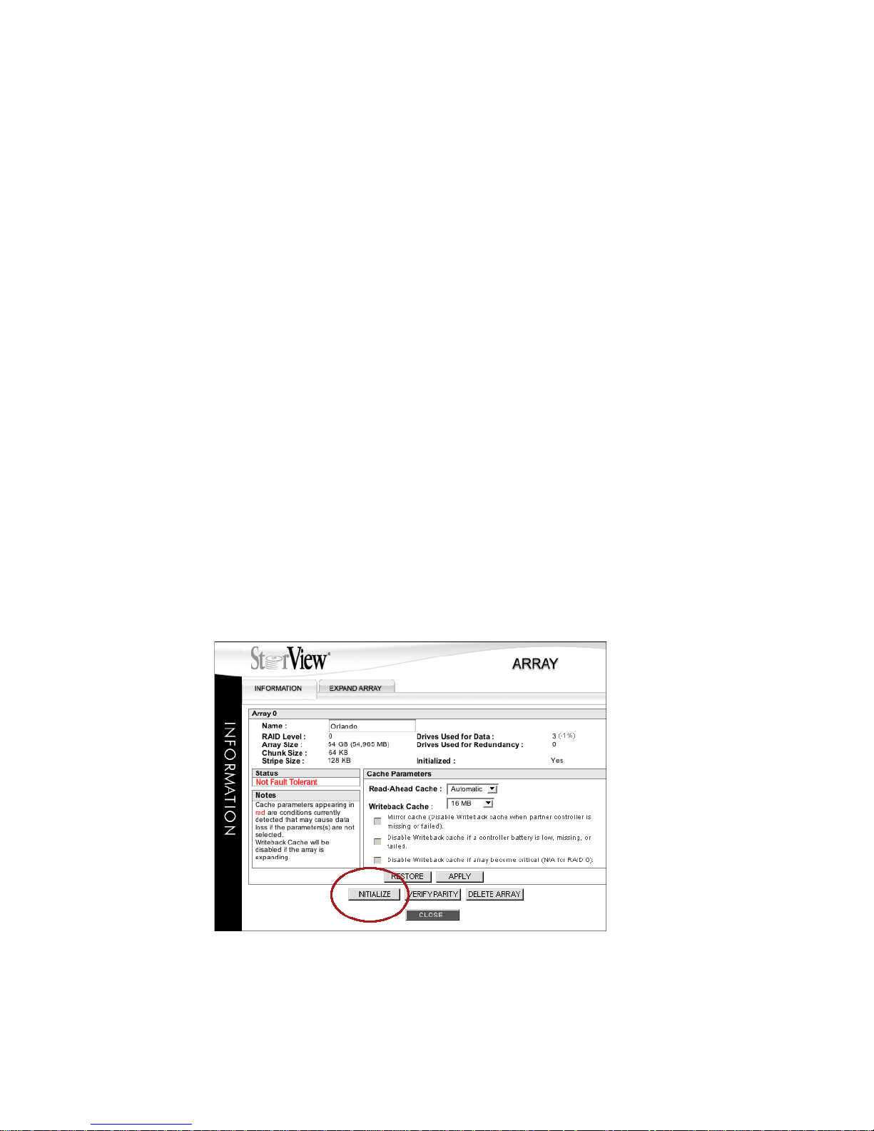
Configuring a Storage Solution
55
6.3 Initializing the Array
Initializing an array clears all the data from the drives. This ensures the validity of the data and parity
stored on the array member drives.
Two features of initialization are background and parallel. Once the array is created, initialization
automatically begins in the background. While initialization is in progress, logical drives can be created
and the disks are made immediately available to the operating system at which time data can be loaded.
As array’s are created and the initialization begins, you can have up to sixty-four (64) arrays initialized in
parallel at the same time. You may also choose to stop the initialization, or pause an initialization and
then resume it at a later time. The controls for managing are displayed on the Main screen next to the
“Array_Name” after the initialization has started. If you Stop an initialization, the array will be
automatically Trusted, see note below.
The array can be initialized at a later time in which you could choose the option to Trust. This option
should only be used in environments where the user fully understands the consequences of the function.
The trust option is provided to allow immediate access to an array for testing application purposes only.
Note A trusted array does not calculate parity across all drives and therefore there is no known state on the
drives. As data is received from the host parity is calculated as normal, but it occurs on a block basis.
There is no way to guarantee that parity has been calculated across the entire stripe. The parity data will
be inconsistent and so a drive failure within a trusted array will cause data loss. Before you use a trusted
array in a “live” environment, you must initialize it.
1 Locate and click on the <Array_Name> in the Array section on the Main screen you wish to initialize. This
will open the Array Information window.
2 From the Array Information window, click the INITIALIZE button.
3 You will be prompted to enter your password to confirm you wish to initialize the array. Type your
password and click GO. A confirmation message appears indicating the success of the operation, click
the CLOSE button.
Figure 6–8 Array Information Window
Page 64
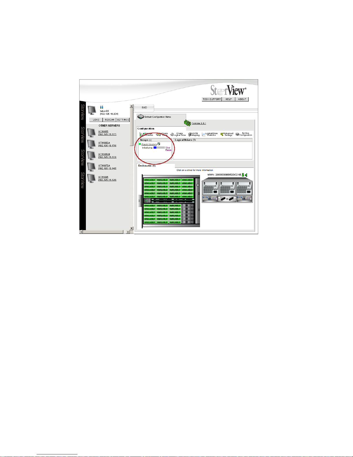
StorView RAID Module
56
4 Click the CLOSE button on the Array screen.
From the Main screen you can monitor the initialization.
Placing the mouse pointer over the progress bar will display the percent complete for the initialization
progress in a pop-up window. The drive member icons of this array will change to an animated icon
indicating the array is initializing.
You can stop the initialization process, if you wish, by clicking the Stop link located to the right of the
progress bar.
6.3.1 Pause/Resume the Initialization
You can temporarily pause the initialization process, and resume the process at a later time.
6.3.1.1 Pause Initialization
1 Click the PAUSE link located just to the right and below the progress bar.
The “Pause” link will change to “Resume” and the progress bar will stop its forward motion.
6.3.1.2 Resume Initialization
1 Click the RESUME link located just to the right and below the progress bar.
The initialization will continue from the point where it was paused.
Figure 6–9 Monitoring the Initialization Progress (RS-4835-F4-5404E Shown)
Page 65
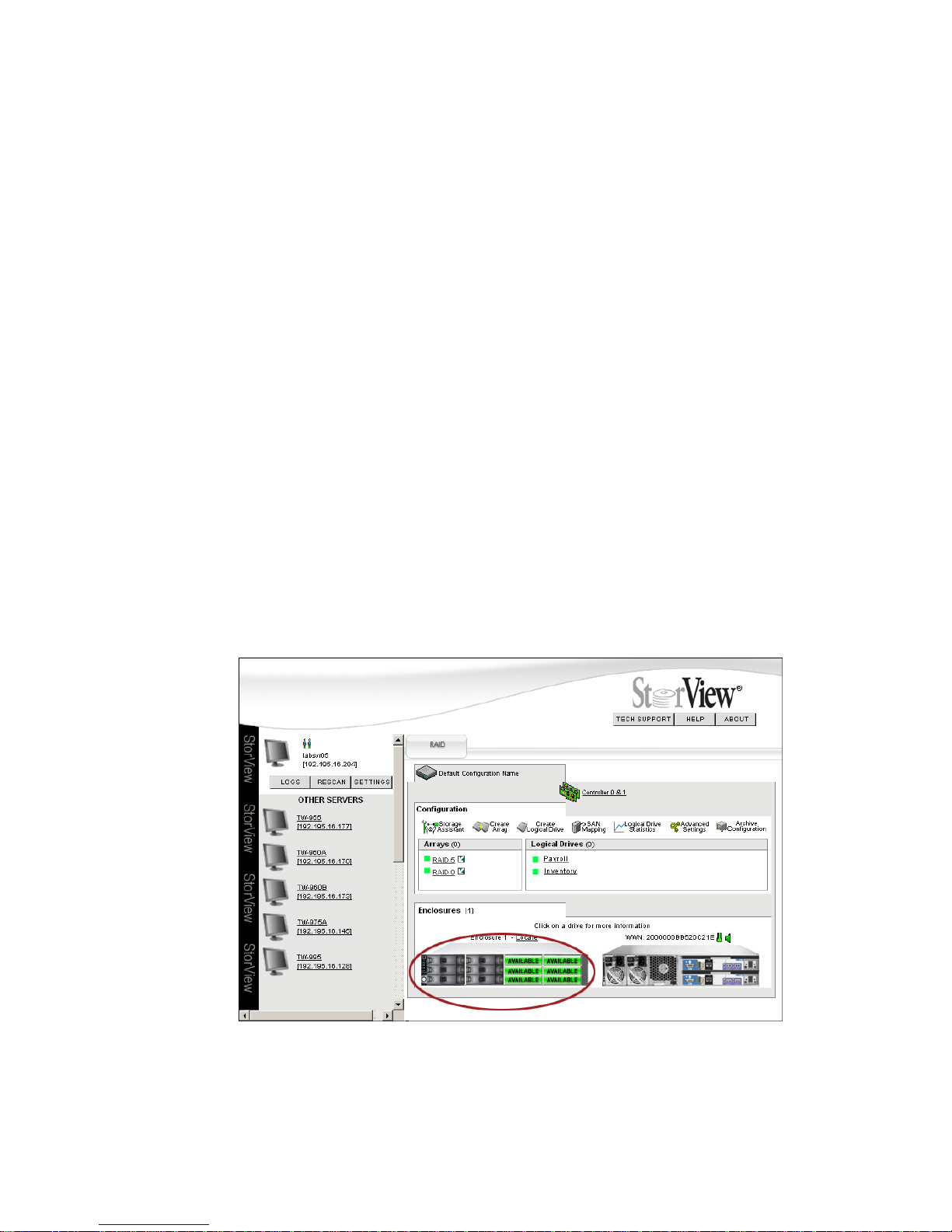
Configuring a Storage Solution
57
6.4 Adding Hot Spare Drives
Hot-swappable spare disk drives are supported. In the event of a drive failure, the controller will use either
a global spare or a dedicated spare to replace a failed drive that is a member of a fault tolerant array. The
process of configuring redundant arrays includes assigning one or more drives as hot spares.
Global spares are not assigned to a specific array and when created they can be used by any array as
the replacement drive.
A dedicated spare is assigned to a specific array and can only be used by that array. It should be the
same size or greater as the drive’s that comprise the array.
Spare Drive Use Rules:
– Drives must be equal to or greater than the capacity of the array drive members.
– You cannot mix drive types in the same array, all SATA or all SAS.
– You cannot mix drive types in the same enclosure column of drives, all SATA or all SAS.
– You cannot mix SATA drive MUX Transition card types, all A/P or all A/A MUX Transition cards.
Note: You may get a variety of messages, warnings, or failure notices when attempting to use a
non-supported drive configuration.
6.4.1 Assigning a Global Spare
1 From the Main screen, click a drive icon within the enclosure front view indicating “Available” that you
wish to make a global hot spare.
Note: There must be at least one drive online and available that meets the rules from above to be
assigned as a hot spare, and a configuration must exist (at least one array defined).
Figure 6–10 Main Screen (RS-1220-F4-5412E Shown)
Page 66
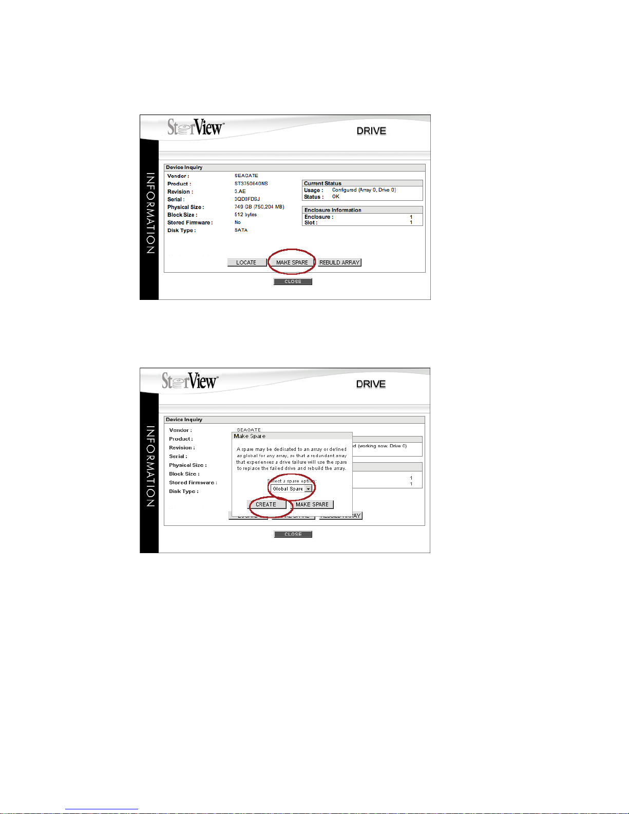
StorView RAID Module
58
2 From the Drive Information window, click the MAKE SPARE button.
3 A pop-up window will appear, select Global Spare from the drop down menu.
4 Click the CREATE button. You will see a confirmation window indicating the process was successful,
click the CLOSE button.
5 Click the CLOSE button on the Drive Information window.
6.4.2 Assigning a Dedicated Spare
1 From the Main screen, click a drive icon in the enclosure front view indicating “Available” that you wish
to make a dedicated hot spare.
Figure 6–11 Drive Information Window
Figure 6–12 Selecting for a Global Spare
Page 67
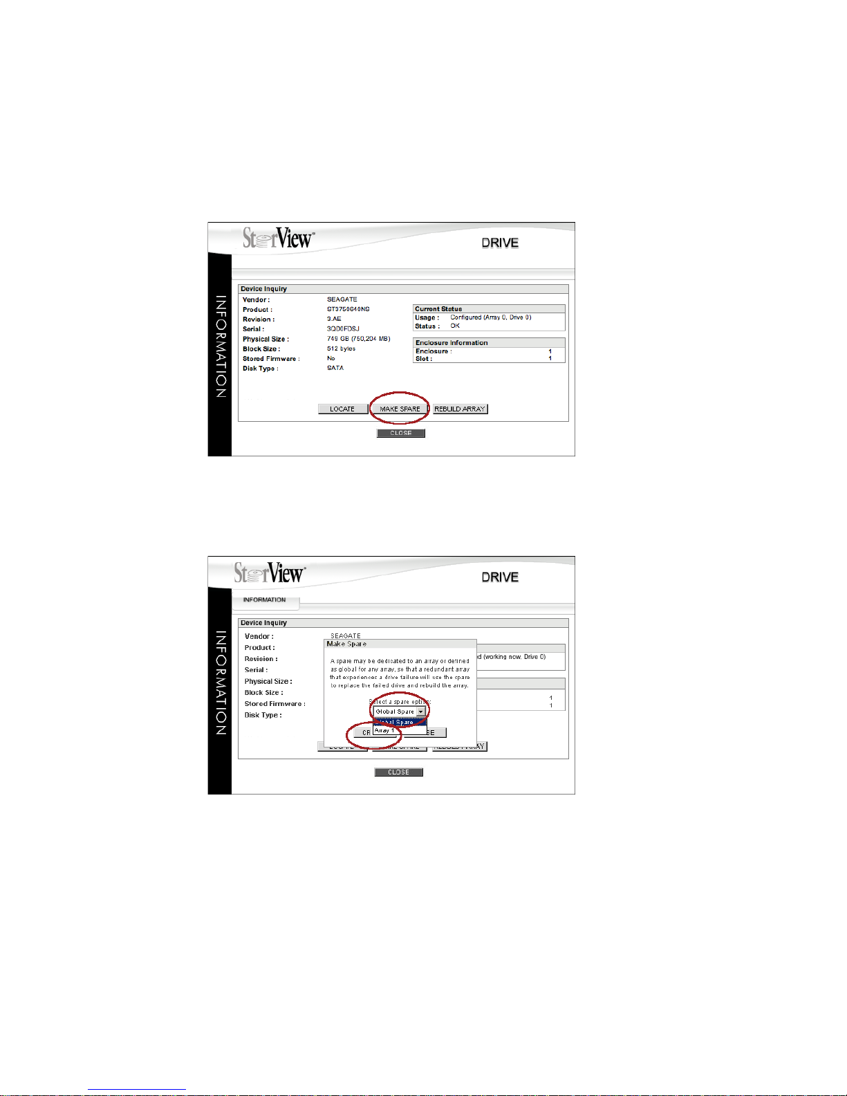
Configuring a Storage Solution
59
Note: There must be at least one drive online and available that meets the rules for spare drives
on page 57 to be assigned as a hot spare, and a configuration must exists (at least one array
defined).
2 From the Drive Information window, click the Make Spare button.
3 A pop-up window will appear, click the drop-down menu and select the array to which you wish to assign
the dedicated spare.
4 Click the CREATE button. A confirmation window will appear indicating success, click the CLOSE button.
5 Click the CLOSE button on the Drive Information window.
Note Only arrays that the spare drive is large enough to replace any member drive of that array or of the same
drive type will be displayed in the pull down menu. For example, if you have two arrays one created using
500 GB drives (array 0) and one using 750 GB disk drives (array 1). If you have a 500 GB spare drive
that you attempting to assign to an array, only Array 0 will be displayed because the drives in array 1 are
of equal or lesser capacity drives then the spare. However, if you have a 750 GB spare drive both Array
0 and Array 1 will be displayed since the 750 GB spare is equal to or greater than any drive in either array.
Figure 6–13 Drive Information Window
Figure 6–14 Selecting a Dedicated Spare
Page 68
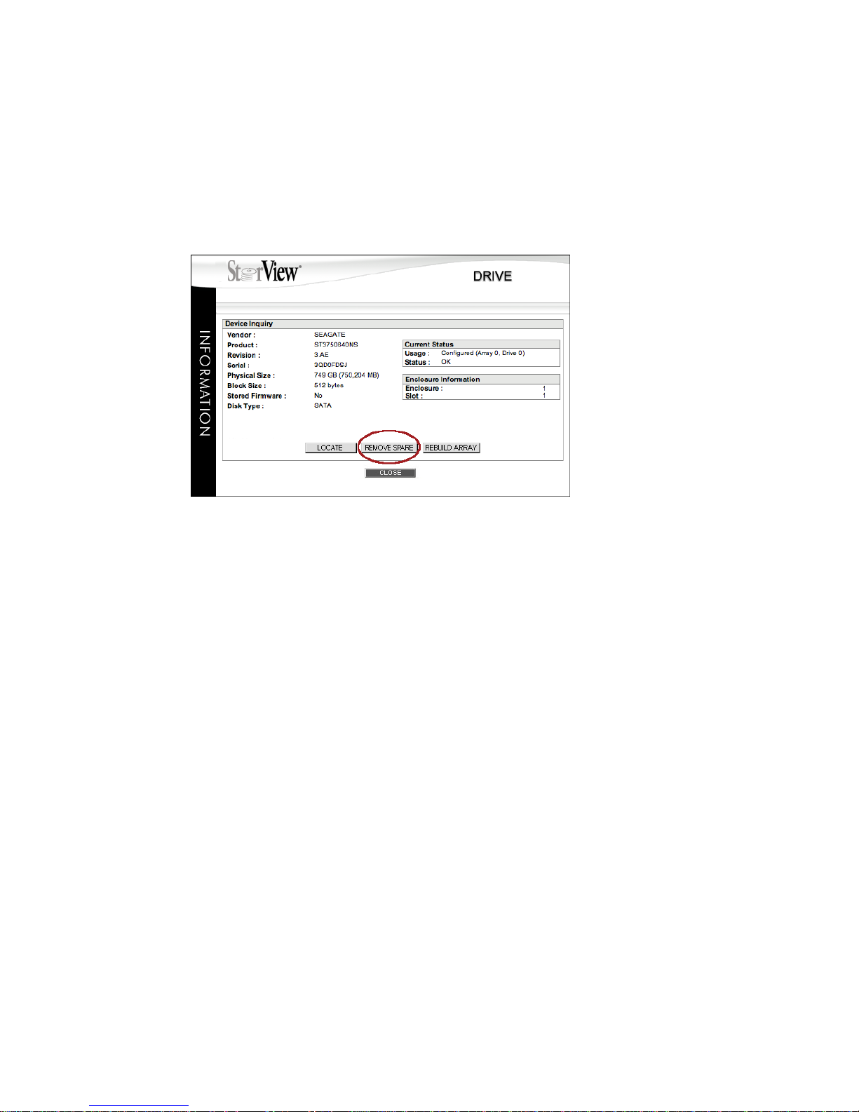
StorView RAID Module
60
6.4.3 Removing a Spare
This operation will remove the designation of the drive as a global or dedicated spare. The drive will then
become online and available for other uses.
1 From the Main screen, click on a disk drive labeled “Dedicated” or “Global” in the enclosure front view
that you wish to remove as a spare. The Drive Information window will open.
2 Click the REMOVE SPARE button. A confirmation window will appear indicating success, click the
CLOSE button.
3 Click the CLOSE button on the Drive Information window.
Figure 6–15 Drive Information window
Page 69
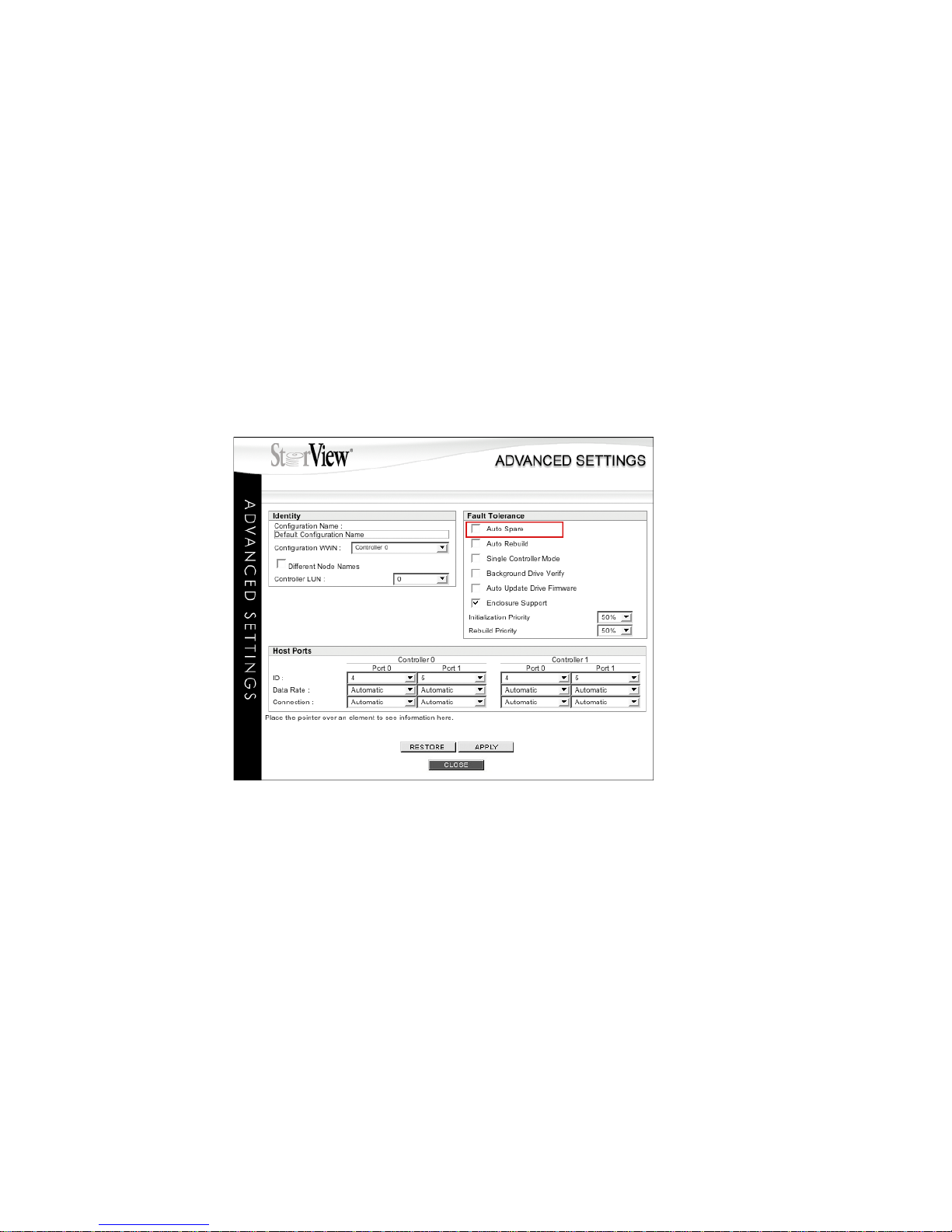
Configuring a Storage Solution
61
6.4.4 Auto Spare
The Auto Spare option, when enabled, will automatically cause a replacement disk drive when inserted
to be used as a dedicated hot spare for the failed drive and its array. When a new drive is inserted in
place of the failed drive, a rebuild operation will begin automatically using the new drive. This option is
useful when a global or dedicated hot spare drive is not assigned and you have a fault tolerant array that
experiences a drive failure. This option allows the user to just insert a replacement drive and the rebuild
will begin, instead of opening the Drive Information window for the replacement disk drive and assigning
it as a hot spare. Refer to the Spare Drive Rules on page 57.
1 To enable this feature, click the Advanced Settings icon on the Main screen Tool Bar. The Advanced
Settings window will open.
2 Place the mouse pointer on the check box next to the Auto Spare parameter and click to place a check
mark enabling the feature.
3 Click the APPLY button and click the CLOSE button on the confirmation window when it appears.
4 Then click the CLOSE button on the Advanced Settings window.
Figure 6–16 Advanced Settings Window
Page 70
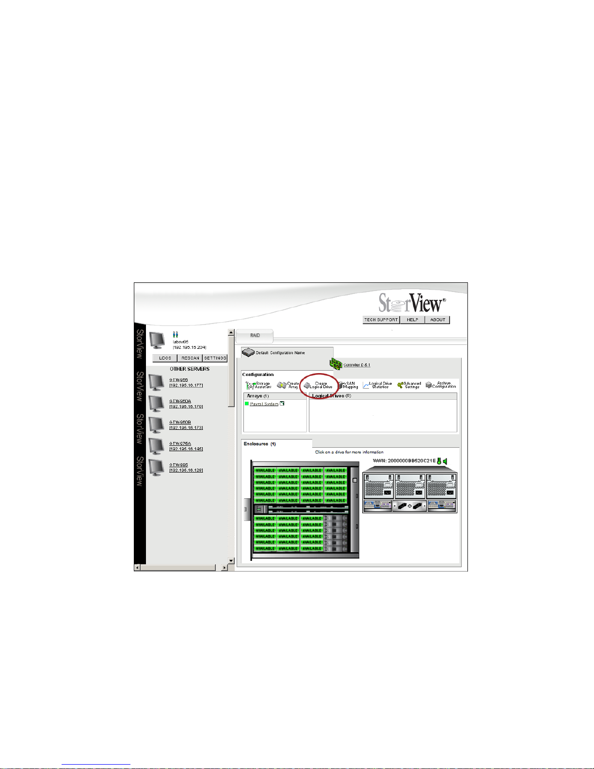
StorView RAID Module
62
6.5 Create the Logical Drive
To complete the process of configuring your storage solution, you will need to create one or more logical
drives. During creation you will assign a LUN to the logical drive, this presents the logical drive to the host
operating system. Up to 512 logical drives are supported.
A logical drive is defined or created from regions of an array, a whole array, or a combination of regions
of different array(s) that can be made available as a single disk to one or more host systems. If you are
creating a logical drive greater than 2 TB, please refer to your operating and file system documentation
to verify it supports such sizes.
You may wish to avoid choosing combinations of a region from one array and from another array to create
your logical drive. This will reduce data fragmentation.
1 From the Main screen click on the Create Logical icon in the Tool Bar.
2 Select the region or regions you wish to use for your logical drive from the list “Select Which Array(s) to
use” window. You may hold the <Shift> or <Ctrl> key down to make multiple selections.
3 Enter a name for your logical drive, you may use up to 32 characters. The default names for logical drives
follow the format “LDx.” Only 12 characters plus an ellipse is displayed when the name is longer. Holding
the mouse pointer over the logical drive name on the Main screen will show the complete name in a
popup.
Figure 6–17 Main Screen (RS-4835-F4-5404E Shown)
Page 71
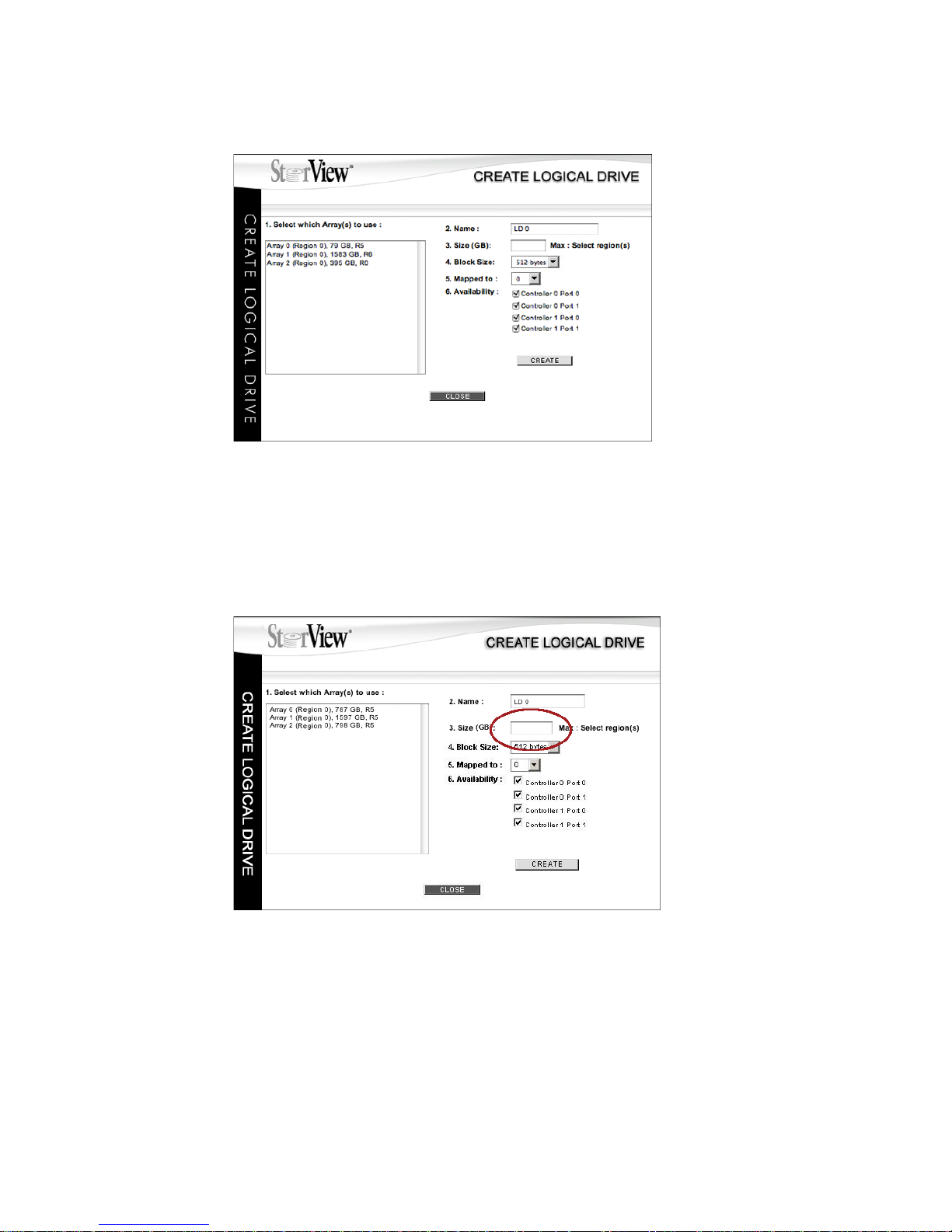
Configuring a Storage Solution
63
4 Enter the size in GB’s for the logical drive capacity.
As you select your regions, the maximum size is displayed to the right of the “Size:” field. You may use
all or some of these regions for this logical drive. If you are creating a logical drive greater than 2,198 GB
(2 TB), please refer to your operating and file system documentation to verify it supports such sizes.
Important If you intend to make your Snapshots available as logical drives (Virtual LUNs (VLUN)), you must
SAN LUN Map all logical drives. That includes regular logical drives and the snapshot logical
drives. Any settings made in the Create Logical Drive screen regarding Availability will be
overridden by the SAN LUN Mapping process.
5 Choose the desired Block Size. (With this release only the 512 byte block size selection is available. No
change is required here.)
6 Select the LUN number for the logical drive from the “Mapped to” drop down menu
.
Figure 6–18 Create Logical Drive Screen
Figure 6–19 Defining the Logical Drive Capacity Screen
Page 72

StorView RAID Module
64
7 Select the Controller Ports you wish to make the logical drive available through. Place a check mark next
to the desired controller ports displayed.
The choices are: C0P0, C0P1, C1P0, and/or C1P1. Where C0 represents the left or lower controller and
C1 represents the right or upper controller, and P0 indicates the port marked Host 0, FC Host 0, or “IN” 0,
and P1 represents the port marked Host 1, FC Host 1, or “IN” 1 on each controller. There is a one-to-one
relationship between the controller port selected and a data cable connected to that port. Ensure that the
ports you select are properly cabled.
8 Click the CREATE button to finish creating the logical drive.
You will receive a screen prompt that the command was successful, click the CLOSE button. If the
command was unsuccessful, review the settings for incorrect parameters and hardware for operational
status.
9 You may continue to create more logical drives or exit by clicking the CLOSE button.
In most storage system environments, creating the logical drives, assigning them their logical unit number
(LUN) and setting the availability is sufficient to meet the requirements for setup. For more advanced and
complex systems using storage area networks you may wish to perform the more advanced SAN LUN
Mapping, see ”SAN LUN Mapping” beginning on page 69. Otherwise access your operating system to
make the new drives available for use.
Page 73
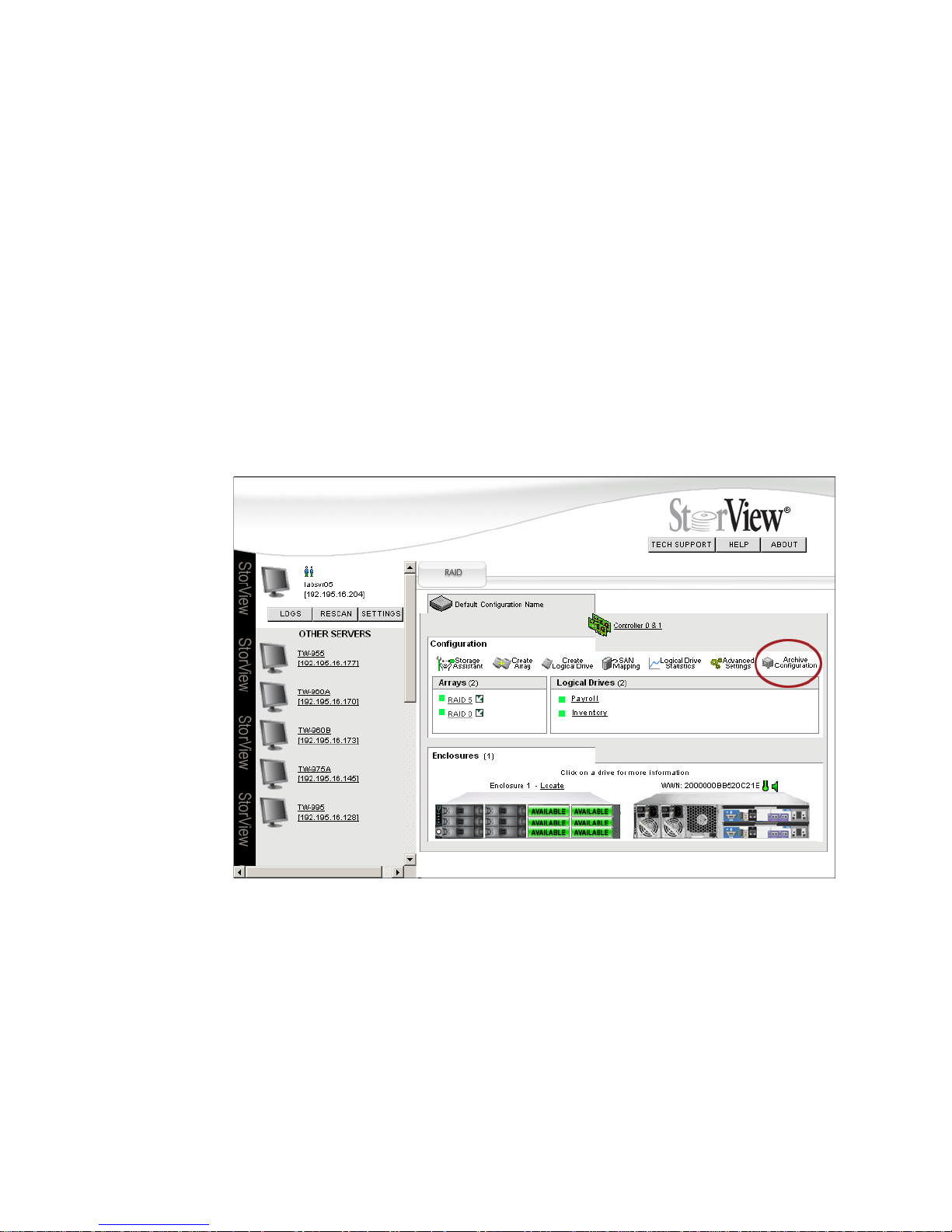
Configuring a Storage Solution
65
6.6 Saving the Configuration
Saving the configuration information is a very useful feature of StorView. When you create or make
changes to arrays, logical drives, hot spares, SAN LUN Mappings, Snapshots, or change the parameters
of a specific controller setting, a file is written (known as the configuration) to all the disk drives that are
members of the array. StorView has the ability to capture that file allowing you to save it to an external
file. Should the situation occur where a configuration is cleared, you are instantly able to re-establish your
storage system by restoring the configuration from the external file. It is recommended to periodically
save the configuration.
Caution If you cannot restore the configuration exactly as it was, you will not be able to restore access to the data
and it will be lost.
6.6.1 Saving the Configuration
1 From the Main screen Tool Bar click the Archive Configuration icon.
The Configuration Archival Operations window appears.
2 Click the SAVE button. You may click the CLOSE button to cancel and return to the Main screen.
Figure 6–20 Main Screen (RS-1220-F4-5412E Shown)
Page 74
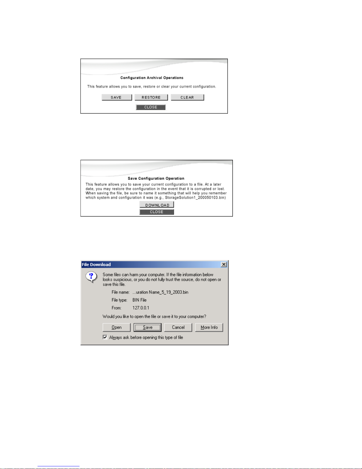
StorView RAID Module
66
3 Click the DOWNLOAD button to continue with saving the configuration file, or click the CANCEL button
to cancel.
4 You are presented with the browser’s standard “File Download” screen. Click the SAVE button to
continue, or CANCEL to quit.
5 Next, you are presented with the “Save As” screen. If you wish to use the default file name, select the
directory and click the Save button, otherwise enter the name you wish to use and specify the directory,
and then click Save. Click the Cancel button to exit.
Figure 6–21 Configuration Archival Operations Window
Figure 6–22 Save Configuration Download Window
Figure 6–23 Save Configuration File Screen
Page 75
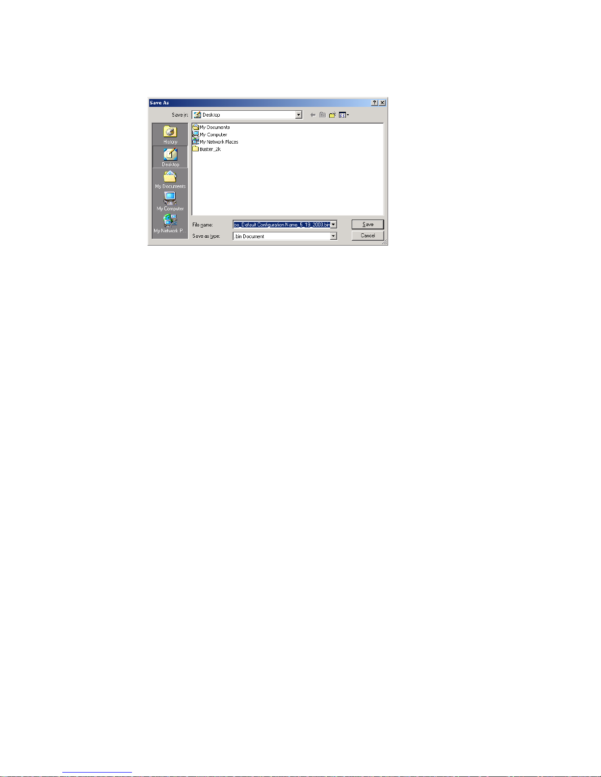
Configuring a Storage Solution
67
6 After a successful download, you will see a confirmation window. Click the CLOSE button.
Figure 6–24 File Name Screen
Page 76

StorView RAID Module
68
Page 77
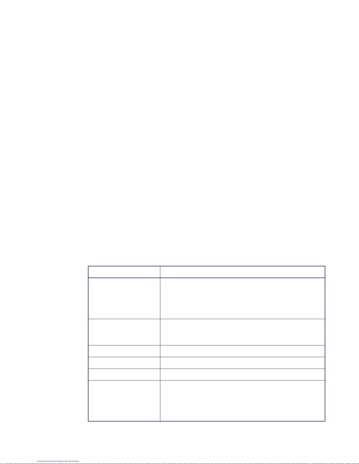
SAN LUN Mapping
69
Chapter 7
SAN LUN Mapping
7.1 Overview
When attaching more than one host system to a storage system, it may be necessary to more precisely
control which hosts have access to which logical drives. In addition to controlling availability on a
controller port by port basis, it is also possible to further restrict access to a specific host system or single
adapter in a host system by the use of SAN LUN Mapping. Up to 512 SAN LUN Mappings are supported.
7.2 Terminology
The following table describes the terminology relating to StorView’s SAN LUN Mapping.
Term Description
Node Name This is an eight byte, 16 character hexadecimal number, uniquely
identifying a single fibre device. It incorporates the World Wide Name
and two additional bytes which are used to specify the format. In a host
system with multiple FC ports, all adapters will typically use the same
Node Name, but unique Port Names.
HBA Port Name (Port Name)
This is an eight byte hexadecimal number, uniquely identifying a single
host HBA port. It incorporates the World Wide Name and two additional
bytes which are used to specify the format and indicate the port number.
Mapping Name A 32 character name that can be used to identify the host system.
Read/Write Access A host may read and write to the logical drive.
Read Only Access A host may only read from a logical drive.
*Used in another Mapping This notation marks a logical drive that has been mapped to another
Host HBA Port, but is available to be mapped to the selected Host HBA
Port. It will be displayed when the condition above has occurred and
appears in the Logical Drive pull-down menu selections. The logical
drives with other mappings will have an asterisk next to the name.
Page 78
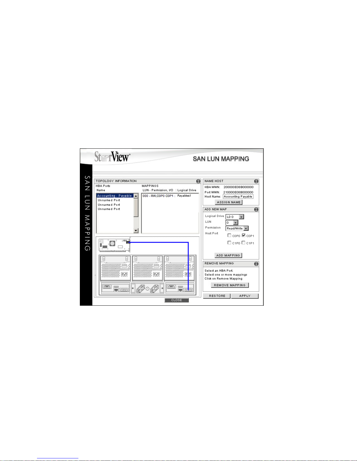
StorView RAID Module
70
7.3 Accessing SAN LUN Mapping
Clicking the “SAN Mapping” icon in the Tool Bar on the Main screen will open the SAN LUN Mapping
window. Here you will find a list of the specific host HBA ports and their mapping details. You can view,
name, create and remove mappings from this window. If no mappings are present, you may create a new
mappings using the “Add New Map” feature. If a mapping exists, selecting a HBA Port Name will display
the current mapping(s) and its parameters.
In the Topology
Information
section you will find information related to the host port or HBA Initiator ID
selected. When you select an HBA Ports Name item the information displayed about the mapping will be
the LUN (logical unit number) assigned to the logical drive, read/write permissions, the controller port for
the connection and the logical drive’s name.
Figure 7–1 SAN LUN Mapping Screen (RS-4835-F4-5404E Shown)
Page 79
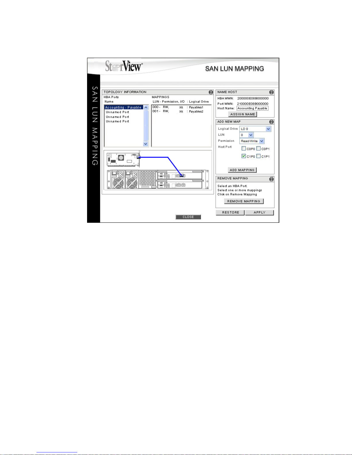
SAN LUN Mapping
71
Figure 7–2 SAN LUN Mapping Screen (RS-1220-F4-5402E Shown)
Page 80
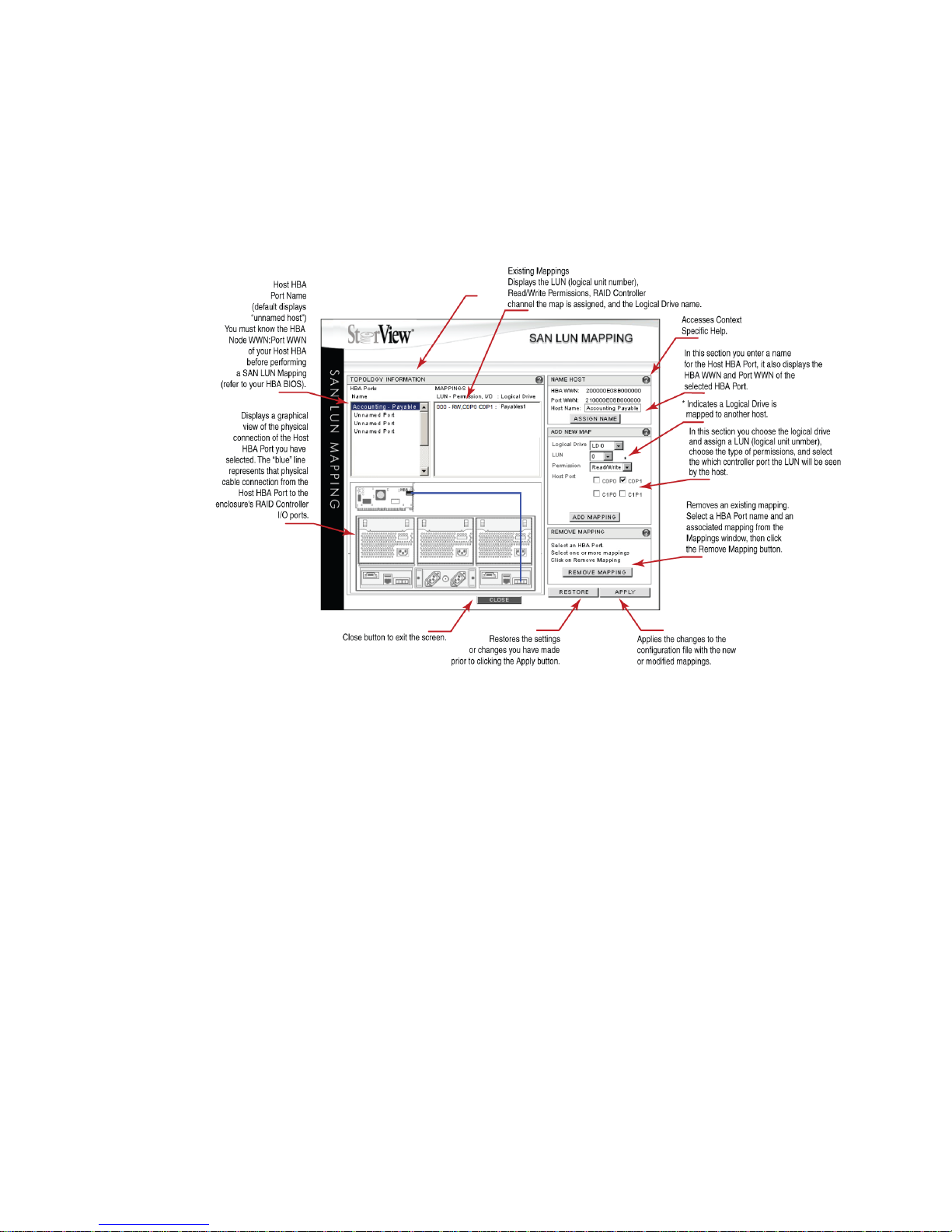
StorView RAID Module
72
7.4 Overview: SAN LUN Mapping Window
The illustration below provides an explanation of each component of the SAN LUN Mapping window. A
graphical illustration of the physical connection from the Host HBA Port to the enclosure’s controller port
is provided to help you visualize the topology being mapped.
The SAN LUN Mapping window is basically divided into two primary sections. The first section on the left
side of the window encompassed in the box titled “Topology Information” displays the list of discovered
Host HBAs and the current mappings for that selected port name. The second section displayed on the
right hand side of the window provides tools for adding, modifying and deleting SAN LUN Mappings.
7.4.1 HBA Ports Name Section
This section provides a list of the discovered named and unnamed fiber channel HBA Ports.
You must select a port and identify it in the Name Host section on the right hand side of the window to
perform the mapping. Once you identify the port, it will be very helpful to rename it to a user defined name.
In the HBA Ports Name section is a list of the discovered unnamed/named fibre channel HBA Ports.
Select an unnamed port and identify it using the displayed HBA Node WWN and HBA Port WWN under
the Name Host section on the right hand side of the window. Enter a name for the port in the Name Host
section and click the ASSIGN NAME button.
Figure 7–3 SAN LUN Mapping Example (RS-4835-F4-5404E Shown)
Page 81

SAN LUN Mapping
73
7.4.2 ADD NEW MAP Section
In this section you will locate the logical drive to which you will be mapping to, assign a LUN (logical unit
number) to the logical drive, set the permissions of the mapping, and select which ports or channels of
the controller you want the logical drive to be seen on.
In the ADD NEW MAP section, the option “Host Port” displays the following choices for your controller:
C0P0, C0P1, C1P0 and C1P1. Where C0 represents the left or lower controller and C1 represents the
right or upper controller, and P0 indicates the port marked Host 0, FC Host 0, or “IN” 0, and P1 represents
the port marked Host 1, FC Host 1, “IN” 1 on each controller. Choose the ports you want the logical drive
to be seen and to which you have cables connected.
7.4.3 SELECTED HOST HBA PORT CONNECTION Section
In the SELECTED HOST HBA PORT CONNECTION section, a graphic appears when a Host HBA Port
is selected, and illustrates the physical connection from the Host HBA Port to the connector at the rear
of the enclosure. This enables you to see the physical topology while performing the mapping, which is
helpful to fully implement the supported topology you selected during the hardware configuration and
setup.
(This option is not applicable to switch configurations.) In an Active-Active configuration one might setup
a fail-over mapping where one Host HBA Port is connected to the Host 0 port on the controller and the
other Host HBA Port is connected to the Host 1 port on the controller. When a “Fail-Over” condition occurs
the hardware re-routes the connection, and the results are seen by clicking the HBA Port that you
mapped for the “failed-over” condition and you will see the mapping is now on this port and not on the
failed port. This provides a visual confirmation of a failover.
Page 82
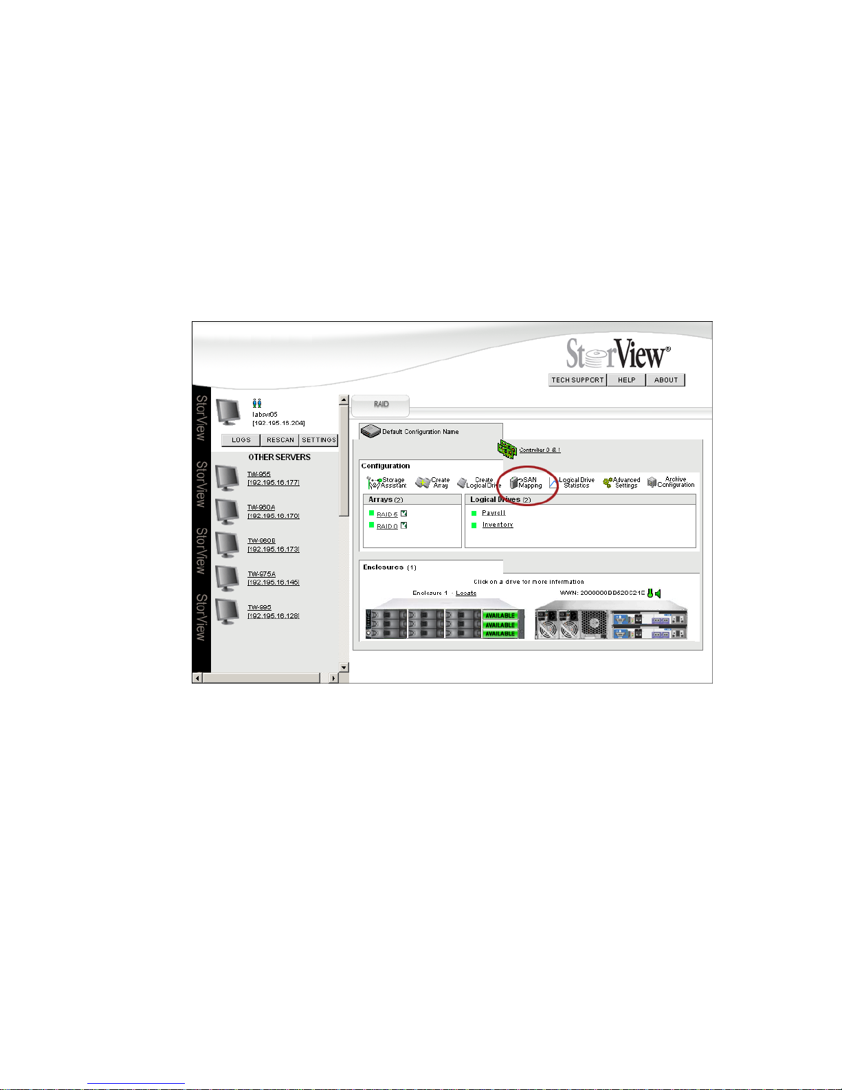
StorView RAID Module
74
7.5 Creating a SAN LUN Mapping
The following are the steps to create a SAN LUN Mapping. The process involves identifying the Host Port,
creating a user defined name, assigning your mapping a LUN number, establishing the access
permissions, and selecting the controller port to make available the mapped logical drive.
Important If you intend to make your Snapshots available as logical drives (VLUNs), you must SAN LUN Map
all logical drives. That includes regular logical drives and the snapshot logical drives.
1 From the Main screen click the SAN Mapping icon in the Tool Bar.
2 Select and name the Host HBA port or Host HBA Initiator ID.
In the “HBA Ports Name” section, select an unnamed port and identify it using the displayed HBA Node
WWN and HBA Port WWN in the NAME HOST section.
3 In the “NAME HOST” section, enter a user defined name for the HBA Port and click the ASSIGN NAME
button. Refer to the illustrations on the following page.
You may use up to 32 ASCII characters, however only 11 characters are displayed in the HBA Ports
Name field.
Figure 7–4 Main Screen (RS-1220-F4-5412E Shown)
Page 83
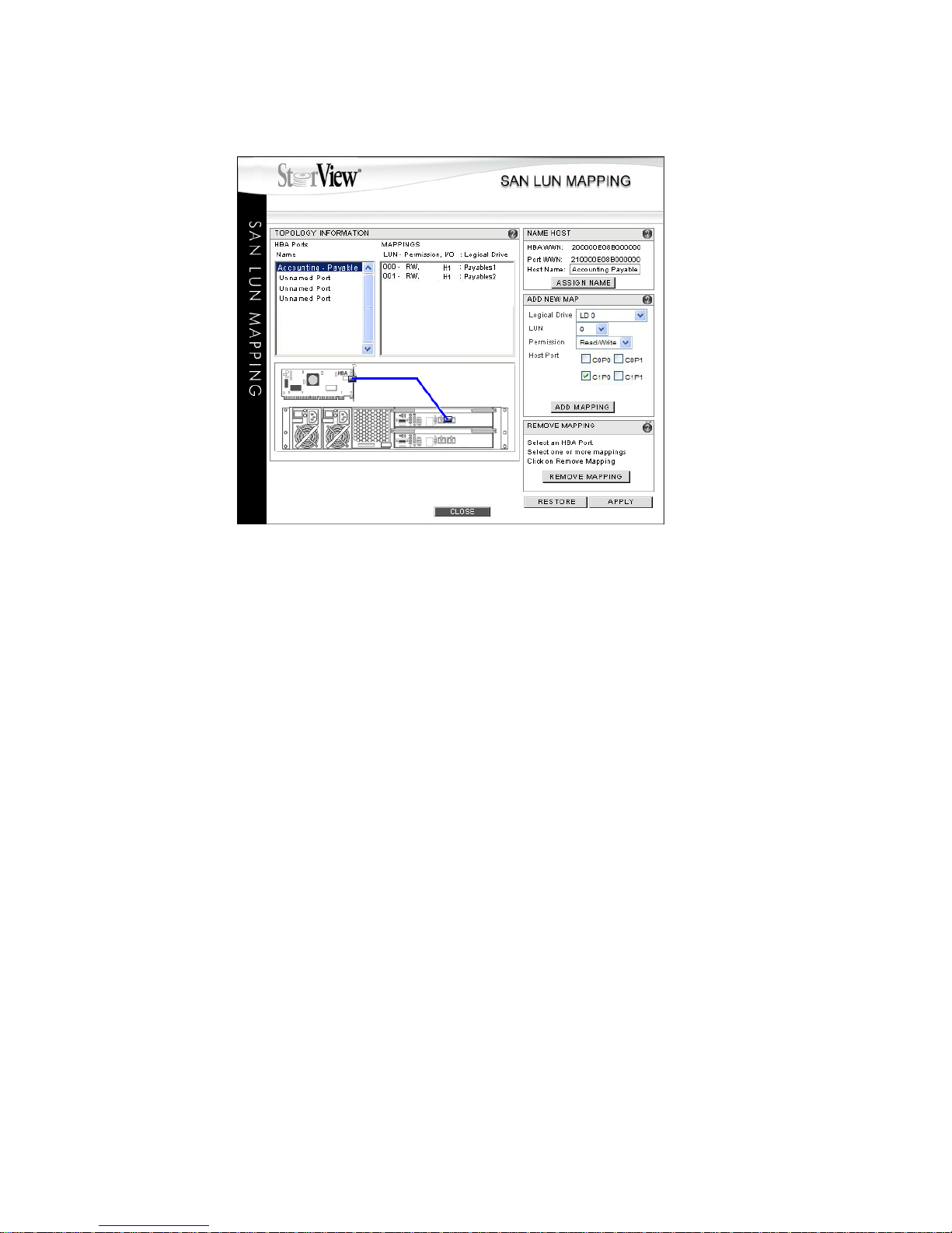
SAN LUN Mapping
75
4 Add a mapping.
In the “ADD NEW MAP” section, do the following:
a Select the logical drive to which you wish to map. Click the pull down menu and choose from the
list of logical drives displayed. Default logical drive names are LD1, LD2, LD3, etc.
Note: Logical drives marked with an asterisk “*” indicate that another mapping for another Host
HBA has been established for this logical drive. You can map it again to additional HBA’s but
know that all Host HBAs mapped to this logical drive will see and have access to this logical
drive.
b Choose the LUN (logical unit number) to present the mapped logical drive to the Host system.
Click the drop-down menu and choose the desired number.
c Select an access permission for the mapping. Choose from the drop-down menu: Read/Write or
Read Only.
Note: Microsoft Windows does not support Read Only permissions.
d Select the Host Port/Channel.
Click the check box(es) for the port that you wish the mapping to be available: C0P0, C0P1,
C1P0, and/or C1P1. Where C0 represents the left or lower controller and C1 represents the right
or upper controller, and P0 indicates the port marked Host 0, FC Host 0, or “IN” 0, and P1
represents the port marked Host 1, FC Host 1, or “IN” 1 on each controller. Ensure that the ports
you select are properly cabled.
e Click the ADD MAPPING button.
Figure 7–5 SAN LUN Mapping Screen (RS-1220-F4-5412E Shown)
Page 84

StorView RAID Module
76
5 Review your settings, then click the APPLY button.
6 You will receive a confirmation, click the OK button to continue, or CANCEL to exit and return to the SAN
LUN Mapping window.
7 You may continue to create more mappings by repeating the above procedures or end this session by
clicking the CLOSE button.
Page 85
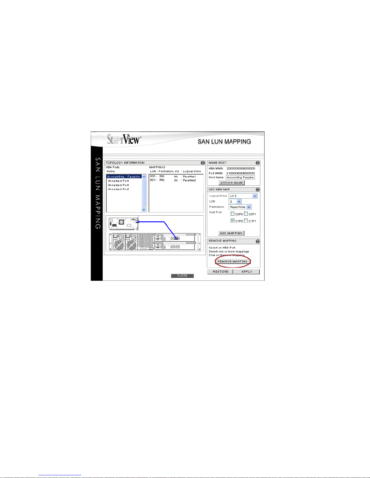
SAN LUN Mapping
77
7.6 Deleting a SAN LUN Mapping
Note Prior to deleting SAN LUN Mappings, clear your web browser’s cache (With Internet Explorer the function
is known as deleting Temporary Internet Files). Then proceed with removing the mappings
1 From the Main screen click the SAN Mapping icon in the Tool Bar.
2 Select a Host HBA port or the user name you gave the port under the “HBA Ports Name” section that
contains the mapping to be removed.
3 Select the Mapping to remove from the “MAPPINGS” section. If there are multiple mappings for this Host
Port, and you want to remove them all, you can shift-click to select all the mappings.
4 Click the REMOVE MAPPING button and click APPLY.
5 You will receive a confirmation, click the OK button to continue, or CANCEL to exit and return to the SAN
LUN Mapping window.
6 You may continue to remove more mappings by repeating steps 2 through 5, or end this session by
clicking the CLOSE button.
Figure 7–6 SAN LUN Mapping Screen (RS-1220-F4-5412E Shown)
Page 86
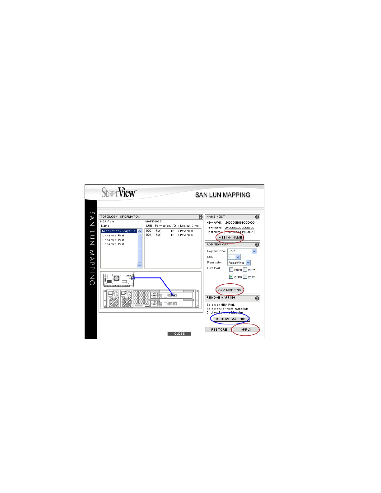
StorView RAID Module
78
7.7 Modifying a SAN LUN Mapping
In order to make changes to an existing SAN LUN Mapping, you must first remove the existing SAN LUN
Mapping and then re-create it with the changes.
Caution Making changes to these mapping parameters may have an adverse affect on other mappings or to the
operating system accessing the logical drive.
1 From the Main screen click the SAN Mapping icon in the Tool Bar.
2 Select a Host HBA port under the “HBA Ports Name” section that contains the mapping to be modified.
3 Select the mapping to be modified from the “MAPPINGS” section.
Note Make a note of the settings for this mapping to use in step 6.
4 Click the REMOVE MAPPING button.
5 You will receive a confirmation, click the OK button to continue, or Cancel to exit and return to the SAN
LUN Mapping window.
6 Add the new mapping. Follow the procedures to add a new mapping and refer to your notes from the
existing mapping to help create the new mapping. For specific details, see 7.5 ”Creating a SAN LUN
Mapping” beginning on page 74.
Essentially you want to re-create the mapping except using the new settings you want for example a
different logical drive, a new LUN, different permissions and/or different controller host ports.
7 Click the APPLY button to save your changes.
Figure 7–7 SAN LUN Mapping Window (RS-1220-F4-5412E Shown)
Page 87

SAN LUN Mapping
79
Note If you wish to cancel your changes before you click the APPLY button, click the RESTORE button and
the changes will be cleared restoring the previous settings.
If you are making multiple changes in multiple sessions, clicking Restore will reset the parameters to the
last time the APPLY button was clicked. For example, if you create a new mapping and click APPLY then
change the name of the Host Port and decide you don’t want that change, clicking the RESTORE button
will cancel the name change and the new mapping remains as it was when you clicked the APPLY button
previously.
8 You will receive a confirmation, click the OK button to continue, or CANCEL to exit and return to the SAN
LUN Mapping window.
9 Click the CLOSE button to exit.
Page 88

StorView RAID Module
80
Page 89
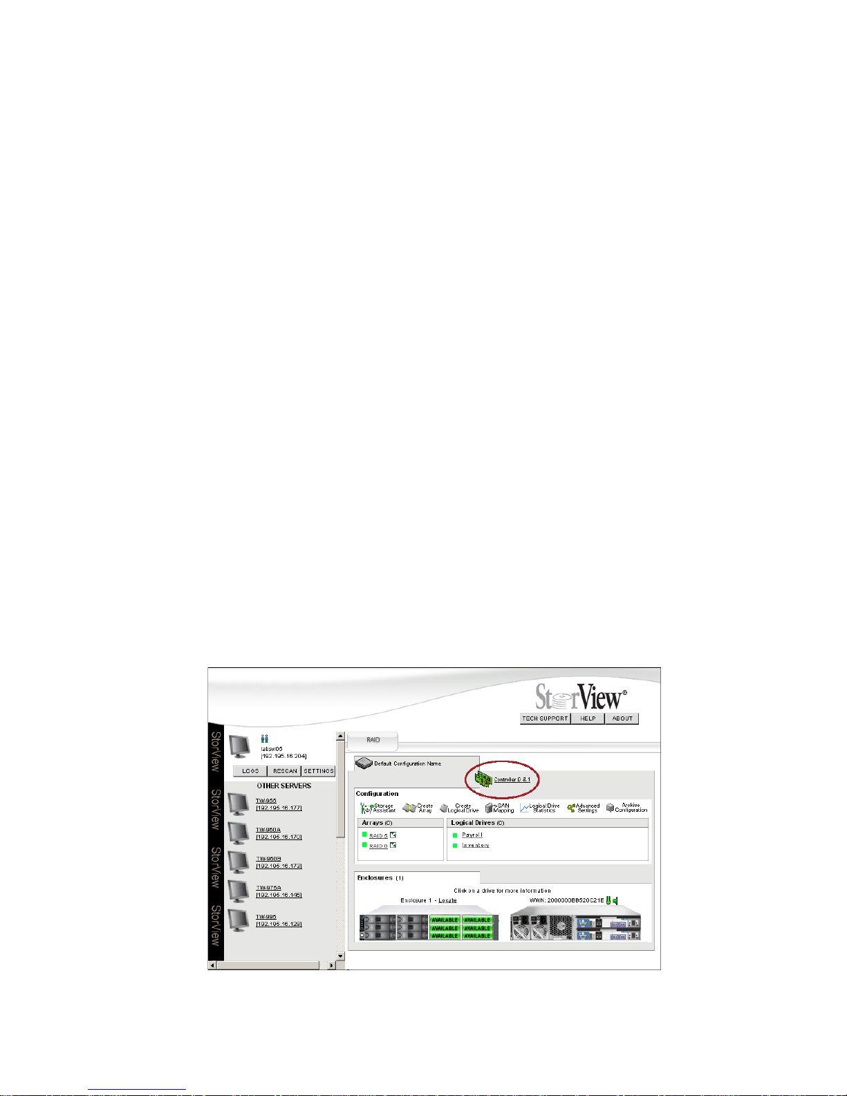
Controller Environmentals
81
Chapter 8
Controller
Environmentals
8.1 Overview
The Controller Information window provides you with a instant view of the health status of the RAID
Controller components and a mouse over function for detailed information of the items listed in the Status
section. User controllable functions include updating RAID Controller firmware, updating the Expansion
module firmware (Disk I/O or EBOD I/O modules), synchronizing the date and time, resetting or shutting
down RAID Controllers, and managing event log files.
8.2 Controller Environmentals
To view controller environmental conditions and manage controller environmental functions, click the
Controller icon located just above the Tool Bar on the Main screen.
Figure 8–1 Main Screen (RS-1220-F4-5412E Shown)
Page 90
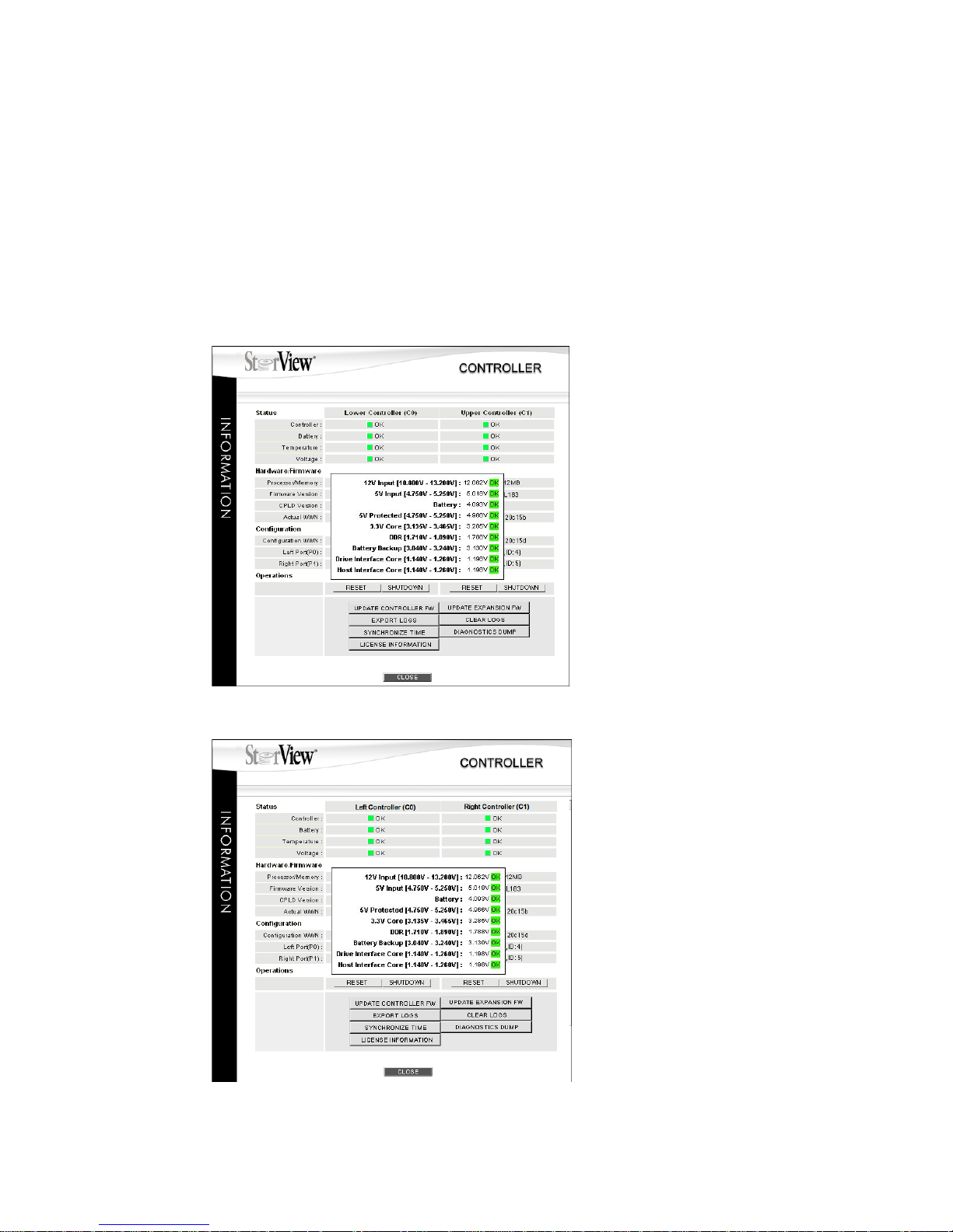
StorView RAID Module
82
The Controller icon on the Main screen will flash red when a problem exists with the controller, indicating
a status change – either error or warning. If this occurs, click the icon and investigate the problem from
the information provided. You may wish to investigate the Event log to verify the event that changed the
controller status, see 14.6.5 ”Controller Port Events” beginning on page 164.
When the Controller Information window opens the controller’s status is displayed using status icons and
a text message.
By passing the mouse pointer over each item in the Status group (controller, battery, temperature and
voltage), a pop-up window will appear with specific detailed data.
Figure 8–2 Controller Window with Pop-Up - Voltage (RS-1220-F4-5412E Shown)
Figure 8–3 Controller Window with Pop-Up - Voltage (RS-4835-F4-5404E Shown)
Page 91

Controller Environmentals
83
8.2.1 Status
This group of items are applicable to the functional status of the RAID Controller. They include general
controller status, battery status, temperature of the controller, and voltage status. Placing the mouse
pointer over the item will display a pop-up window with more detailed information. In the illustrated
example, the mouse pointer is over “Voltage” so the voltage data is displayed. Status icons appear
adjacent to the item in the group along with a text message. Status icon and text message conditions are
defined as green - normal, yellow - warning, and red - failed.
When the mouse pointer is rolled over the Battery status icon, the pop-up display provides the remaining
charge on the battery expressed as a percentage and the length of time the battery will hold the cache
data. A warning icon indicates a below 80% charge (battery is low but most likely charging). An error
indicates below 80% charge and the controller has been powered up for over 24 hours.
8.2.2 Hardware/Firmware
This group of items are applicable to the controller’s physical memory and firmware. From this group you
can determine the type of processor, onboard memory size, the firmware version, and the CPLD
(Complex Programmable Logic Device) firmware version. The controller’s WWN (world wide name) is
presented in this group.
8.2.3 Configuration
This group identifies the WWN (world wide name) assigned to the configuration, the speed of each port
and the LUN assigned to the port. The configuration can be assigned the WWN of any controller
preferably one of the controllers installed in the enclosure. For more information on the configuration
WWN and port LUN assignment, see 9.2.1 ”Identity” beginning on page 92.
8.2.4 Operations
These items include a group of buttons that allow the user to reset and shutdown each controller
individually, update the controller firmware (see 8.2.4.1 on page 83), update the expansion module
(Disk I/O or EBOD I/O module) firmware (see 8.2.4.2 on page 85), export the controller logs (see 8.2.4.4
on page 88) and clear the log files (see 8.2.4.3 on page 87).
Note When choosing to shutdown the RAID Controller(s) for an extended period of time, be sure to verify that
the Cache Active LED on each RAID Controller is NOT illuminated. If it is, wait until the controlling
application has completed writing the data to the disk before continuing with the shutdown. This will
ensure that the backup battery is not holding cache data and will prevent the battery from being drained.
The user can dump the controller’s diagnostic information into a file for use with technical support when
troubleshooting a problem by clicking the DIAGNOSTIC DUMP button.
8.2.4.1 Updating the Controller Firmware
This option provides the means to update the RAID Controller firmware.
The controllers have the ability to automatically update their partners firmware in dual controller
configurations, however the update process behaves differently under certain conditions. If one controller
has a later version of firmware than its partner controller, during the startup process the later version
firmware controller will automatically update the firmware on the lower version controller. If a partner
controller fails in a dual controller configuration, when the failed controller is replaced regardless of its
firmware version it will always be updated to match the surviving controllers firmware.
Page 92
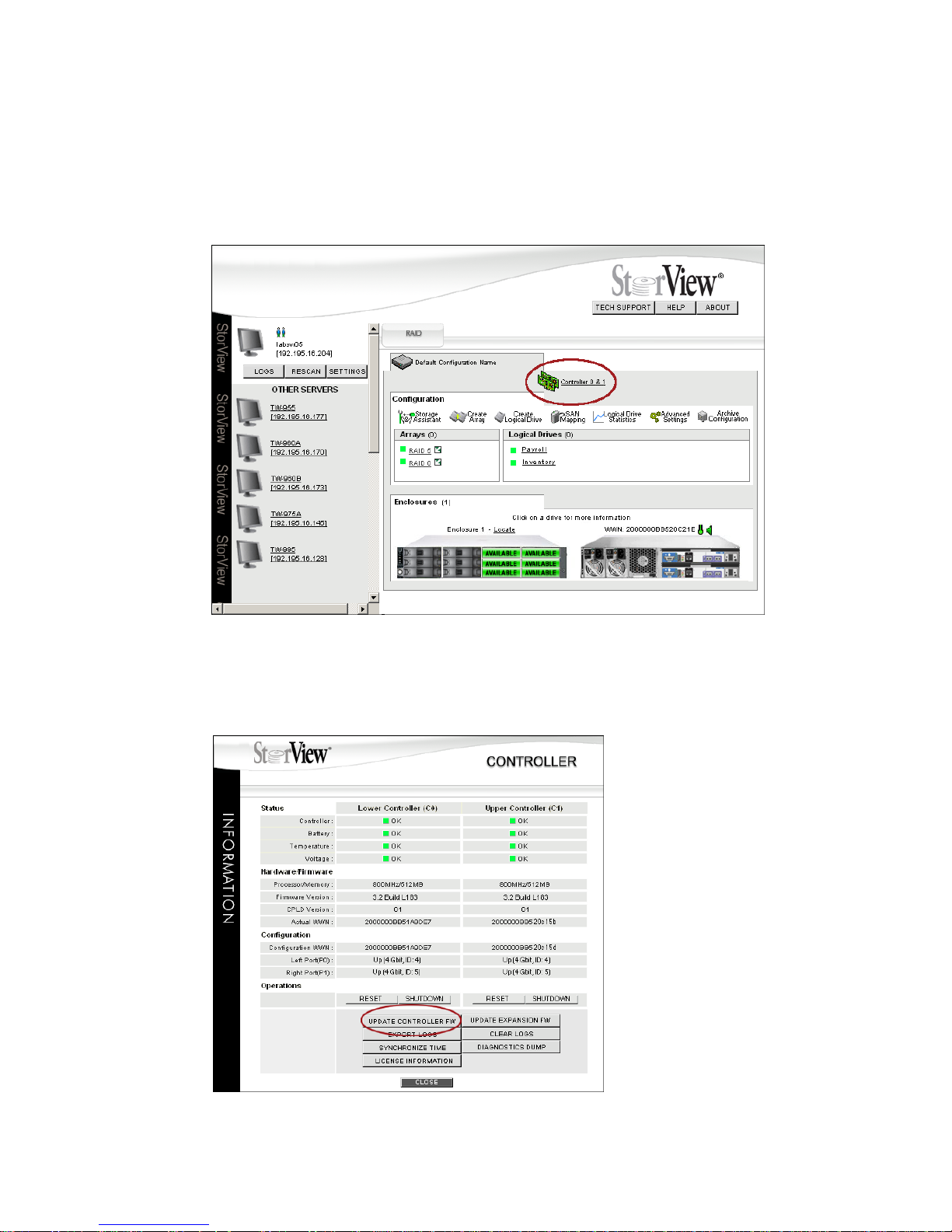
StorView RAID Module
84
If you want to downgrade the firmware version you must shut down one controller and flash the operating
controller. Then shut down the controller which was downgraded, bring the second controller up and flash
its firmware to the lower version. Then start both controllers and resume operations.
1 Click the Controller icon located just above the Tool Bar.
The Controller Information window will open.
2 Click the “UPDATE CONTROLLER FW” button.
Figure 8–4 Main Screen (RS-1220-F4-5412E Shown)
Figure 8–5 Controller Information Window (RS-1220-F4-5412E Shown)
Page 93
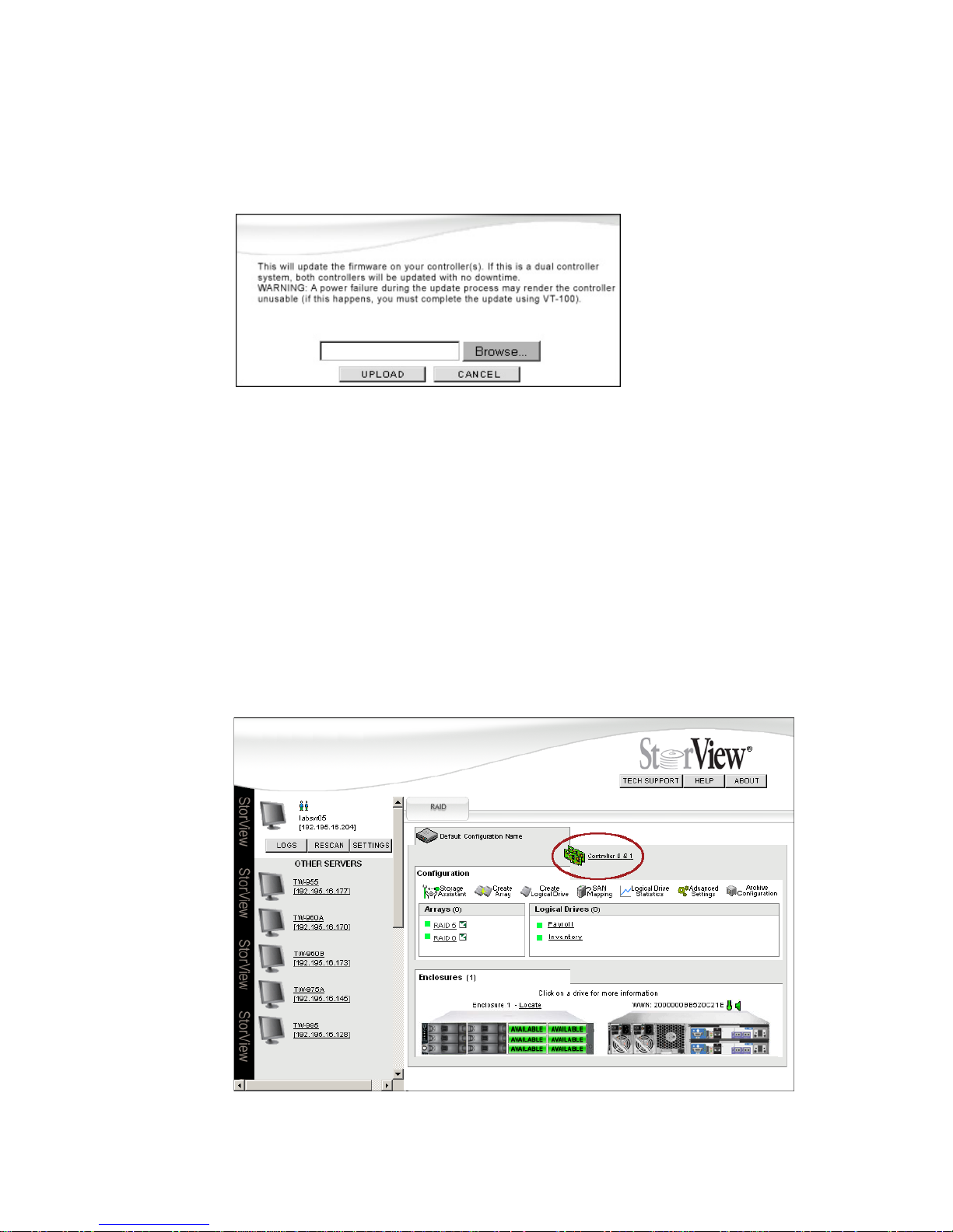
Controller Environmentals
85
3 Locate the firmware file, click the Browse button. The file will be named similar to “I_320_0179.bin.”
The file will be made available from the customer service representative or technical support.
4 After locating the file, click the UPLOAD button.
You will see an acknowledgement window appear indicating the status of the update, followed by the
controller automatically restarting.
Note For more information on License Information, see 1.3.2 ”Feature License” beginning on page 3.
8.2.4.2 Updating the Expansion Module Firmware
Note On the RS-1220-E3-XPN enclosure, the expansion module is named the Disk I/O module and on the RS-
4835-E3-XPN enclosure, the expansion module is named the EBOD I/O module. This operation updates
either system.
1 Click the Controller icon located just above the Tool Bar. The Controller Information window will open.
Figure 8–6 Firmware Upload Window
Figure 8–7 Main Screen (RS-1220-F4-5412E Shown)
Page 94
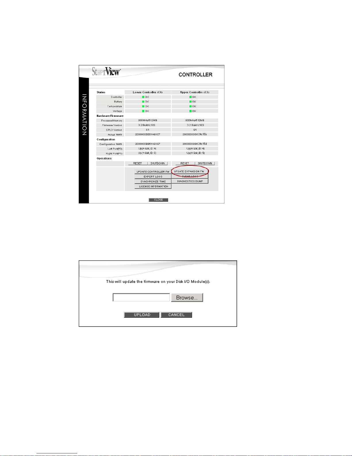
StorView RAID Module
86
2 Click the UPDATE EXPANSION FW button.
3 Locate the firmware file, click the Browse button. The file will be named similar to
“fw_1220_SAS10_0105.bin.”
The file will be made available from the customer service representative or technical support.
4 After locating the file, click the UPLOAD button.
You will see an acknowledgement window appear indicating the status of the update, followed by the
expansion module automatically restarting. The RAID Controller will restart after the expansion module
restarts
Figure 8–8 Controller Information Window (RS-1220-F4-5412E Shown)
Figure 8–9 Firmware Upload Window
Page 95
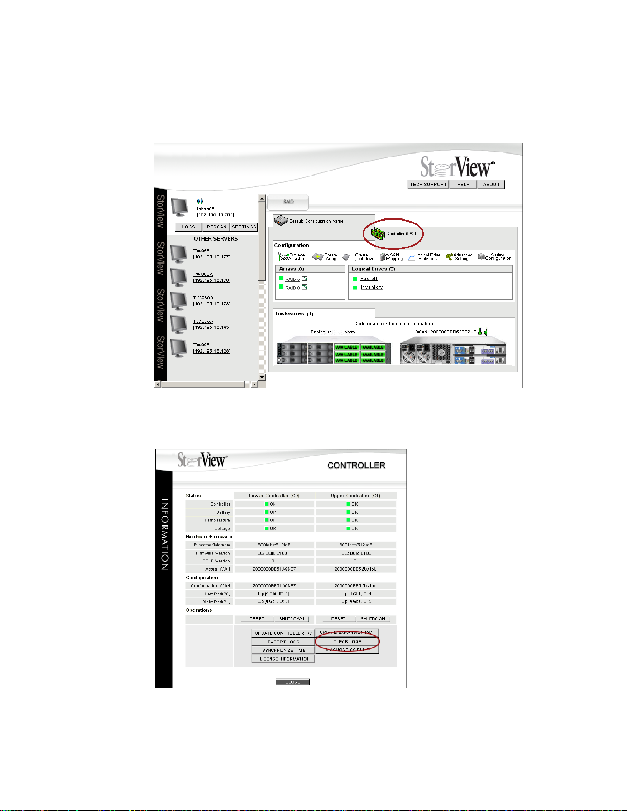
Controller Environmentals
87
8.2.4.3 Clearing the Controller Logs
1 Click the Controller icon located just above the Tool Bar.
The Controller Information window will open.
2 Click the CLEAR LOGS button.
Figure 8–10 Main Screen (RS-1220-F4-5412E Shown)
Figure 8–11 Controller Information Window (RS-1220-F4-5412E Shown)
Page 96
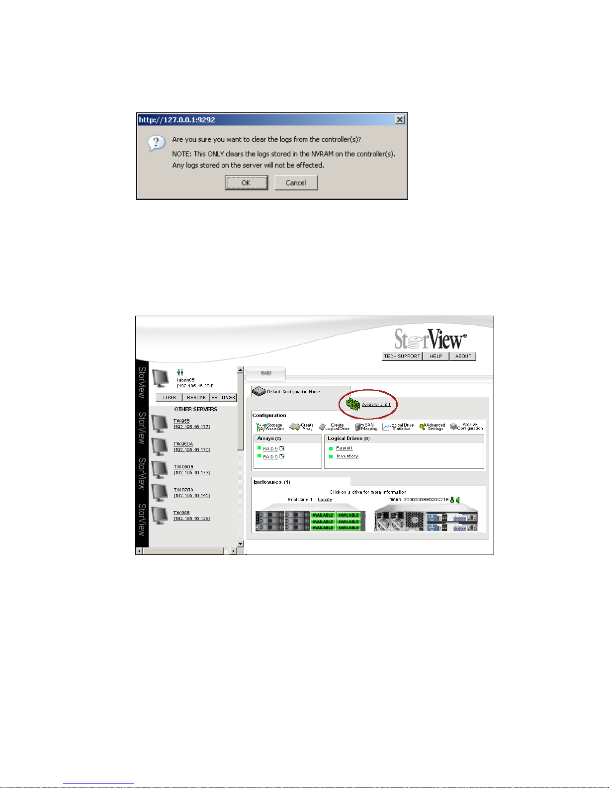
StorView RAID Module
88
3 A window opens prompting to confirm clearing the logs. Click the OK button.
4 Click the CLOSE button at the bottom of the Controller Information window.
8.2.4.4 Exporting the Controller Logs
1 Click the Controller icon located just above the Tool Bar.
The Controller Information window will open.
Figure 8–12 Confirmation WIndow
Figure 8–13 Main Screen (RS-1220-F4-5412E Shown)
Page 97
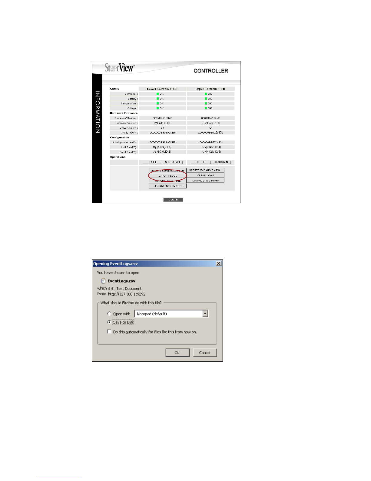
Controller Environmentals
89
2 Click the EXPORT LOGS button.
3 Choose Save to Disk, enter a name and location for the file, then click the OK button.
4 Click the CLOSE button at the bottom of the Controller Information window.
5 Open the event log with a text editor program.
Figure 8–14 Controller Information Window (RS-1220-F4-5412E Shown)
Figure 8–15 Confirmation WIndow
Page 98

StorView RAID Module
90
Page 99
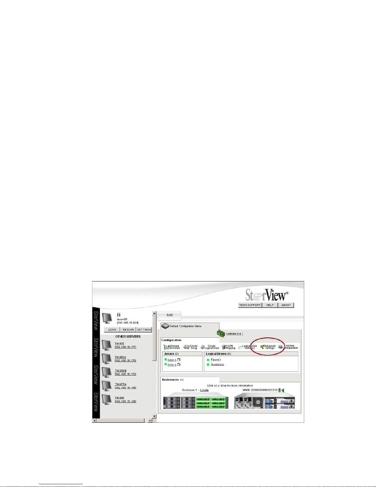
Controller Advanced Settings
91
Chapter 9
Controller Advanced
Settings
9.1 Overview
In the Controller Information window you can view the status of the controller and perform certain
controller operational functions. Since your storage solution may be different from another, you may want
to make changes to the controller parameters to optimize the system for your application. This is
accomplished through the Advanced Settings window.
9.2 Advanced Settings
Click the Advanced Settings icon in the Tool Bar on the Main screen.
Figure 9–1 Main Screen (RS-1220-F4-5412E Shown)
Page 100
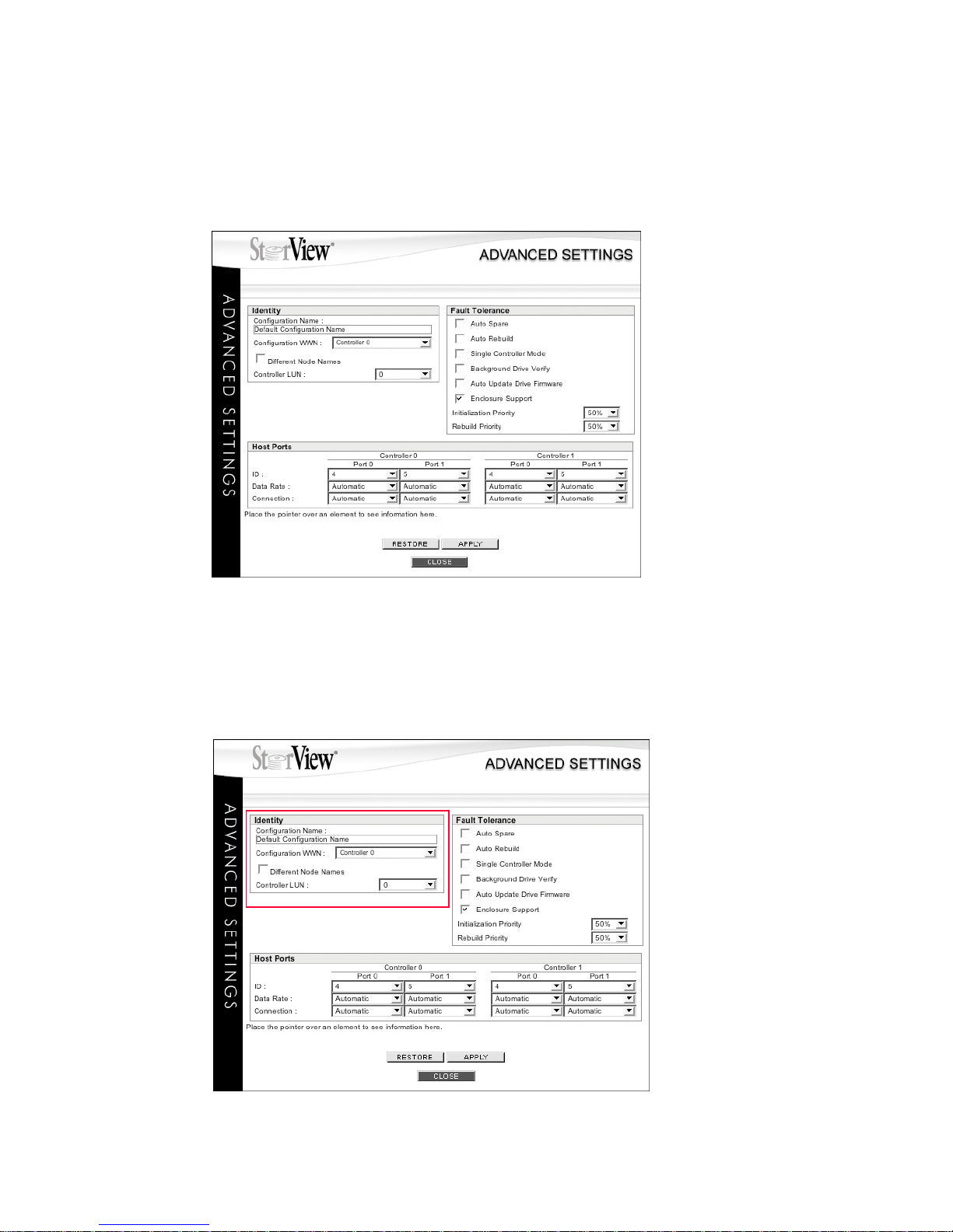
StorView RAID Module
92
The Advanced Settings window will appear. From this window you are able to make changes to controller
parameters, enable or disable Fault Tolerant features, and configure the controller’s host ports.
The Advanced Settings window is divided into three sections; Identity, Fault Tolerance and Host Ports.
9.2.1 Identity
In the Identity section, you can make changes to the Configuration Name, assign the configuration the
WWN of either controller, and set the LUN (logical unit number) for the controller.
Figure 9–2 Advanced Settings Window
Figure 9–3 Advanced Settings Window
 Loading...