

Page 1

LaCie DDS4 Drive User’s Manual
Page 2

Copyrights
Copyright © 2002 LaCie. All rights reserved. No part of this publication may
be reproduced, stored in a retrieval system, or transmitted in any form or by
any means, electronic, mechanical, photocopying, recording or otherwise,
without the prior written consent of LaCie.
Trademarks
Apple, Mac and Macintosh are registered trademarks of Apple Computer, Inc.
Sony is a registered trademark of Sony Electronics. Microsoft, Windows 98,
Windows 98SE, Windows 2000 and Windows Millennium Edition are
registered trademarks of Microsoft Corporation. Other trademarks mentioned
in this manual are the property of their respective owners.
Changes
The material in this document is for information only and subject to change
without notice. While reasonable efforts have been made in the preparation of
this document to assure its accuracy, LaCie assumes no liability resulting from
errors or omissions in this document, or from the use of the information
contained herein. LaCie reserves the right to make changes or revisions in the
product design or the product manual without reservation and without
obligation to notify any person of such revisions and changes.
2
Federal Communications Commission Radio Frequency
Interference Statement (FCC)
WARNING: Changes or modifications to this unit not expressly approved by
the party responsible for compliance could void the user’s authority to operate
the equipment. This equipment has been tested and found to comply with the
limits for a Class B digital device, pursuant to Part 15 of the FCC Rules. These
limits are designed to provide reasonable protection against harmful
interference when the equipment is operated in a commercial environment.
This equipment generates, uses, and can radiate radio frequency energy, and
if not installed and used in accordance with the instructions, may cause
harmful interference to radio communications. However, there is no
guarantee that interference will not occur in a particular installation. If this
equipment does cause harmful interference to radio or television reception,
which can be determined by turning the equipment off and on, the user is
encouraged to correct the interference by one of the following measures:
• Reorient or relocate the receiving antennas.
• Increase the separation between the equipment and the receiver.
• Connect the equipment into an outlet on a circuit different from that to
which the receiver is connected.
• Consult the reseller or an experienced radio/TV technician for help.
Shielded cables and I/O cards must be used for this equipment to comply with
the relevant FCC regulations. This device complies with Part 15 of the FCC
rules. Operation is subject to the following two conditions: (1) this device may
Page 3

not cause harmful interference, and (2) this device must accept any
interference received, including interference that may cause undesired
operation.
Canada Compliance Statement
This Class A digital apparatus meets all requirements of the Canadian
Interference-Causing Equipment Regulations.
Manufacturer’s Declaration for CE Certification
We, LaCie, solemnly declare that this product conforms to the following
European standards:
Class B EN60950, EN55022, EN50082-1, EN60555-2
With reference to the following conditions:
73/23/EEC Low Voltage Directive
89/336/EEC EMC Directive
3
Page 4

1. Introduction.........................................................................................5
4
1.1 Icons Used in This Manual
................................................................5
1.2 What is SCSI?....................................................................................6
2. Getting To Know Your LaCie DDS4 Drive.....................................7
2.1 Minimum System Requirements
........................................................7
2.2 LaCie DDS4 Drive – Views ................................................................8
2.3 SCSI Cables and Connectors
.......................................................... 10
3. Setting Up Your LaCie DDS4 Drive............................................. 11
3.1 Installing Your LaCie DDS4 Drive................................................... 11
3.1.1 Software Installation
.............................................................. 12
3.1.2 SCSI Card Verification ........................................................... 12
3.1.3 Setting the SCSI ID Number................................................... 12
3.1.4 Connecting the Drive to the Computer
.................................. 13
3.1.5 Drive Recognition................................................................... 13
4. Using Your LaCie DDS4 Drive...................................................... 15
5. Technical Information
.................................................................... 20
5.1 User Advice When Using SCSI........................................................ 20
6. Troubleshooting
.............................................................................. 24
7. Contacting Customer Service....................................................... 28
7.1 Warranty........................................................................................ 30
8. Appendix 1 – SCSI Questions and Answers
.............................. 31
9. Glossary............................................................................................ 36
10. Health, Safety and General Precautions................................. 40
Page 5
1. Introduction
Congratulations on the purchase of your new LaCie DDS4 drive. LaCie tape
drives deliver a cost-effective, reliable way to protect against devastating data
loss, at home and in the office. Use your new tape drive in conjunction with
effective tape rotation and a detailed disaster recovery plan to make your
critical data virtually untouchable. Based upon standard technology with clear
migration paths, LaCie tape drives are backward compatible to allow for
capacity growth.
With a variety of tape formats and capacities to choose from, LaCie tape
drives are suitable for a range of environments, from workstations and small
networks and servers, to high-end, enterprise-level backup.
With all it can do for you, we’re confident that your LaCie DDS4 drive will
quickly become an important tool in your day-to-day business and personal
computing.
This manual will help you to:
• Install your new device properly
• Get your drive up and running
• Quickly learn how to operate it
5
1.1 Icons Used in This Manual
Italicized paragraphs feature an icon describing the type of information being
given.
Important Note
Warning! (This icon indicates potential hazard).
Precautions
Always follow the basic precautions to use your LaCie DDS4 drive safely and
correctly. Respecting these guidelines will help to avoid the possibility of
personal injury to yourself or others, as well as to prevent damage to your
device and other computer equipment. For a complete list of precautions,
please see Chapter10. Health, Safety and General Precautions of this
manual.
Warranty
LaCie and its suppliers accept no liability for any loss of data during the use of
this device, or for any of the problems caused as a result. As a precaution, it is
Technical Information or News
Page 6

recommended that the tape media be tested after they have been written to.
Under no circumstances do LaCie or its suppliers guarantee the reliability of
the tape media used in this drive.
Manual Updates
LaCie is constantly striving to give you the most up-to-date, comprehensive
User’s Manuals available on the market. It is our goal to provide you with a
friendly, easy-to-use format that will help you quickly install and utilize the
many functions of your new device.
If your manual does not reflect the configurations of the product that you
purchased, please check our Web site for the most current version available.
You can access our manuals at: www.lacie.com/support/manuals
1.2 What is SCSI?
SCSI (Small Computer System Interface) is an industry standard used to
connect peripherals to your computer through a standard hardware interface,
using standard SCSI commands. Currently, there are three generations of the
SCSI interface: SCSI-1, SCSI-2 and SCSI-3, which is made up of at least 14
separate standards documents.
6
For a more detailed discussion of SCSI, please refer to 5. Technical
Information and 9. Appendix 1 – SCSI Questions and Answers.
The SCSI Icon
This icon will help you easily identify the SCSI interface.
It appears on some SCSI cables and next to the SCSI
port connectors on certain computers.
Software
For guidance on application software that can be used with your LaCie DDS4
Drive and the supported operating systems, please contact your reseller or
LaCie Technical Support.
Page 7
2. Getting To Know Your LaCie DDS4 Drive
What can your LaCie DDS4 drive do?
• Archive your database.
• Back up proprietary information.
• Store company files.
2.1 Minimum System Requirements
Hardware Requirements: • Mac or PC equipped with SCSI card or built-in
SCSI interface.
System Requirements: • Mac OS 8.6, 9.x, and OS 10.x
• Windows 95, Windows 98, Windows NT,
Windows 98 Second Edition (SE), Windows 2000,
Windows Me and Windows XP
• Intel Pentium II/350MHz-compatible processor
or greater; minimum 64MB (128MB
recommended) RAM
DDS4 Drive and Cartridge Compatibility
The LaCie DDS4 Drive supports the DDS4, DDS3, DDS2 and DDS1 recording
formats. Compatibility with each of these formats ensures complete write and
read interchange of recorded digital data between all compliant drive and
media vendors.
7
The following DDS cartridges are compatible with the LaCie DDS4 drive:
Model Name / Length / Recording
Capacity
DDS1 M32000 / 90-meter / 2/4GB* X X X
DDS2 M34000 / 120-meter / 4/8GB* X X X
DDS3 STDM24G / 125-meter / 12/24GB* -- X X
DDS4 STMD40 / 150-meter / 20/40GB* -- -- X
STDMCL DDS Cleaning Cartridge X X X
*Capacity is based on 1:2 compression ratio
Important Note: The LaCie DDS4 drive can not use 60-meter DDS1
media.
Important Note: In data compression mode, the LaCie DDS4 drive
typically doubles the storage capacity and transfer rate of the native
uncompressed operation. Tape capacity and sustained data transfer
rate are dependent upon the characteristics of the files being compressed,
along with system parameters such as the speed of the host, the operating
system and the application software used. The LaCie DDS4 drive also offers
synchronous and asynchronous SCSI transfers with a high-speed burst data
transfer rate of 80MB/sec.
DDS2
Drive
DDS3
Drive
DDS4
Drive
Page 8
2.2 LaCie DDS4 Drive – Views
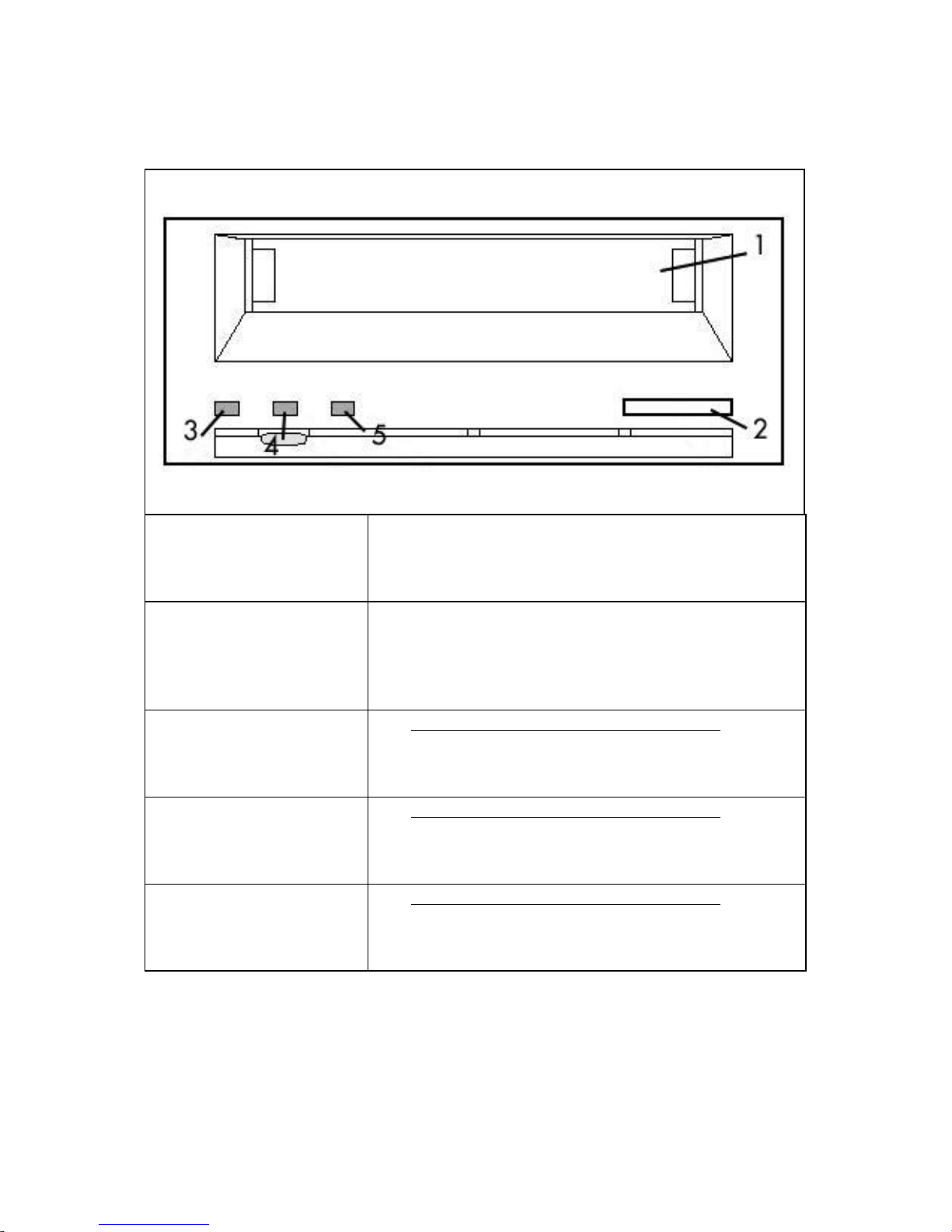
Front View
8
1 – Cartridge Slot Door Insert your DDS cartridge in this door. As you insert
the cartridge, the drive takes hold of it and loads it
into the mechanism.
2 – Eject Button Press this button to eject a cartridge. Do not
attempt to eject the cartridge while the busy LED is
blinking. Doing so may harm the cartridge and
lead to data corruption or loss.
3 – Clean LED See 4. Using Your LaCie DDS4 Drive for
complete information on this LED’s condition
explanation.
4 – Media LED See 4. Using Your LaCie DDS4 Drive for
complete information on this LED’s condition
explanation.
5 – Drive LED See 4. Using Your LaCie DDS4 Drive for
complete information on this LED’s condition
explanation.
Page 9
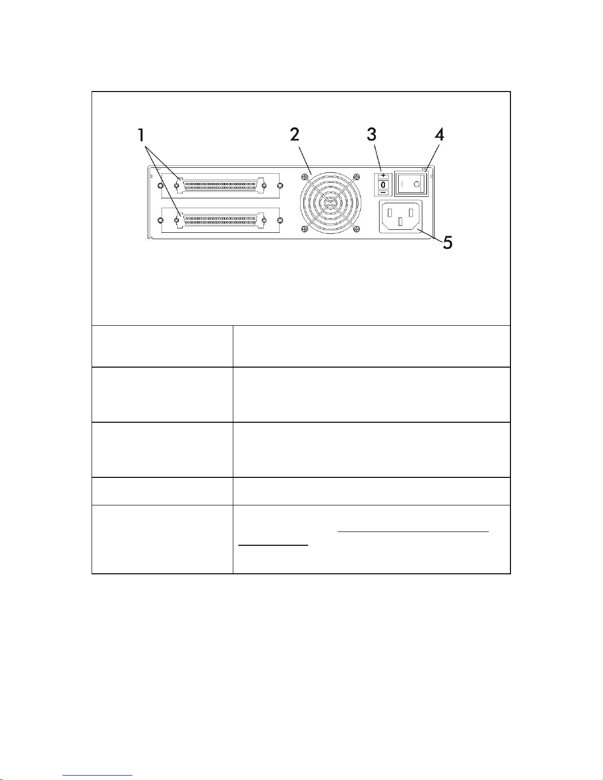
Back View
9
1 – SCSI Connectors This is where you plug in the SCSI cable furnished
with your drive.
2 – Ventilation Fan Helps to keep your drive cool during operation. Be
sure not to block this opening when using your
drive.
3 – SCSI ID Switch Select the SCSI ID for your drive by pushing the
plus or minus signs to move the numbers up or
down.
4 – On/Off Switch Turns the drive on and off.
5 – Power Supply
Connector
This is where you plug in the AC adapter supplied
with the drive. See 3. Setting Up Your LaCie
DDS4 Drive for details on connecting the
adapter.
Serial Number Sticker
This is where you will find your LaCie drive's serial number. Write down the
serial number and keep it in a safe place, because you will need to provide
the number in the event you have to call LaCie Technical Support for any
reason in regard to the drive’s performance. The serial number would also
come in handy if your drive is lost or stolen.
Page 10
2.3 SCSI Cables and Connectors
Ultra2 LVD, Ultra160 LVD & Terminator
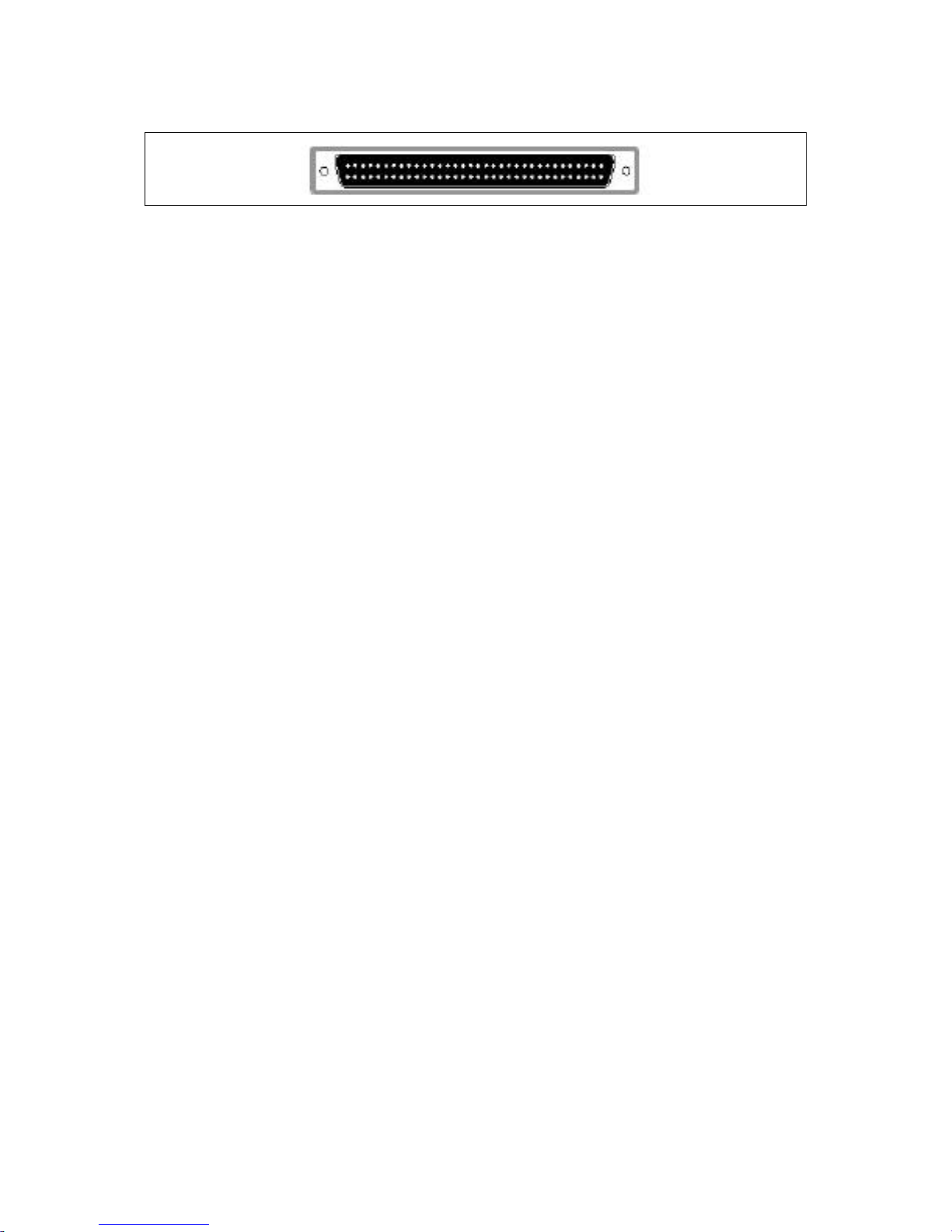
LaCie DDS4 drives are supplied with a 68-pin to 68-pin SCSI interface (also
included with the drive is an LVD terminator). If the SCSI cable supplied with
your LaCie DDS4 drive does not meet your requirements, please contact your
computer supply specialist, who will be able to help you choose the right SCSI
cable for your particular setup and applications.
10
Page 11

3. Setting Up Your LaCie DDS4 Drive
Connecting the AC Adapter
To operate the drive, you must use the AC adapter supplied with it.
Warning! Use only the AC adapter supplied with your LaCie drive.
Using any other power cable may cause damage to the device and
void your warranty.
Important Note: You may use your LaCie drive when in a foreign
country, thanks to its auto-switching 100-240 Volt power supply. To
be able to use this feature, you may need to purchase an appropriate
adapter. Consult LaCie Technical Support for assistance in choosing the right
adapter. LaCie accepts no responsibility for any damage to the drive resulting
from the use of an inappropriate adapter. Using an adapter other than one
authorized by LaCie will void your warranty.
Connecting the AC Adapter to the Drive
1) Insert the AC cable into the power input located at the rear of the drive.
11
2) Connect the wall-side plug to a power socket.
Disconnecting the AC Adapter from the Drive
1) Turn the drive off and wait for it to spin down (+/- 10 sec.).
2) Hold the drive steady with one hand, then remove the plug from the
connector.
Warning! Always remove the AC adapter before transporting your
LaCie drive. Failure to remove the adapter may result in damage to
your drive and will void your warranty.
3.1 Installing Your LaCie DDS4 Drive
There are five main steps to this installation process:
3.1.1 - Software Installation
3.1.2 - SCSI Card Verification
3.1.3 - Setting the SCSI ID Number
3.1.4 - Connecting the Drive to the Computer
3.1.5 - Drive Recognition
Page 12

12
3.1.1 - Software Installation
In order to use your LaCie DDS4 drive, you will need to first install application
software. Unlike a hard disk, CD-R/RW or DVD-RAM/R/RW drive, the DDS4
drive will not be displayed on your Windows or Mac desktop, and will not be
attributed a logical unit letter in Windows. Instead, this drive is managed
entirely by the application software, which displays a list of connected drives.
As a result, when you want to backup your information, you will need to utilize
the application software.
For guidance on application software that can be used with your LaCie DDS4
Drive and the supported operating systems, please contact your reseller or
LaCie Technical Support.
3.1.2 - SCSI Card Verification
Mac Users
To verify that your SCSI card has been installed correctly and is recognized, go
to the Apple System Profiler and click on the Devices and Volumes tab.
Your SCSI bus should be listed. If it does not appear, contact the card
manufacturer.
Windows Users
To verify that your SCSI card has been installed correctly and is recognized, go
to Control Panel > System > (For Windows 2000 and XP, the tab is
Hardware > ) Device Manager tab. Double-click on SCSI Controllers. If an
“ X” or “!” symbol appears next to the icon for the SCSI adapter card, this
means that it has not been installed correctly. If it has not been installed
correctly, try reinstalling it or contact the card manufacturer. For more
information on the installation and configuration of SCSI cards, please contact
the card manufacturer.
3.1.3 - Setting the SCSI ID Number
Before connecting your LaCie DDS4 drive to your computer, you need to set
the unit’s SCSI ID number and, if necessary, terminate the drive.
Each device in your SCSI chain needs a unique ID number, either from 0 to 6
for Narrow SCSI, or any number between 0-6 and 8-15 for LVD/Wide SCSI (ID
7 is generally reserved for your computer’s SCSI controller). Press the top or
bottom button of the SCSI ID selector switch to increase or decrease the SCSI
ID number.
Important Note: The SCSI ID number for each device on the chain
must be unique. Make sure that your LaCie DDS4 drive’s SCSI ID
number is not the same as any other device in the chain.
Page 13

13
Terminating the Drive
Terminators prevent SCSI signals from being reflected off the last device in the
chain, and they help to regenerate the SCSI signal. If your drive is not the last
device in the SCSI chain, there is no need to connect an external terminator.
Your LaCie DDS4 drive requires an external terminator, which is included with
your drive. This terminator should be attached to the open connector on the
back of the drive if your drive is the only SCSI device connected to your
computer, or if it is the last device in your chain of SCSI peripherals.
3.1.4 - Connecting the Drive to the Computer
1) Power down your computer.
Warning! Before connecting the drive’s power supply cable to the
main power outlet, make sure that the drive is turned off! Failure to
do so could lead to serious damage of the drive.
2) Connect your drive’s power supply cable to the main power outlet.
3) Connect one end of your SCSI cable to the SCSI port on your computer, or
to a drive in your SCSI chain, if more than one SCSI peripheral is connected.
Connect the other end of the SCSI cable to either of the SCSI connectors on
your LaCie drive. If, due to connector incompatibility, you are unable to
connect the cable supplied with your LaCie drive to the SCSI port on your
computer, or to the other devices in your SCSI chain, please contact your
computer supply retailer to obtain an appropriate SCSI cable.
4) Power up your LaCie drive and all other peripherals in the SCSI chain first,
then power on your computer.
Important Note: Always power on all of the devices in your SCSI
chain before powering on your computer. This ensures recognition by
the computer’s operating system. Never connect or disconnect any
devices in your SCSI chain while the computer is powered on. Always turn off
your computer before connecting or disconnecting peripherals or powering off
the peripherals.
3.1.5 - Drive Recognition
Mac Users
Open Apple System Profiler and then click on the Devices and Volumes
tab, and your LaCie drive should be listed under the SCSI bus.
Page 14

14
Windows Users
Windows 98 SE and Me – After the operating system has loaded, open the
Control Panel and double-click on the System icon. Select the Device
Manager tab and double-click on hard disk. If the drive has been installed
correctly, it should be listed here.
Windows NT – After the operating system has loaded, open the Control
Panel, double-click on SCSI Adapter and click on the Devices tab.
Windows 2000 and XP – After the operating system has loaded, open
System, double-click on Control Panel, select the Hardware tab, and click
the Device Manager button in System Properties.
Important Note: If an “X” or “!” symbol appears next to the icon for
the LaCie drive, it has not been installed correctly. If this occurs, try
reinstalling your SCSI card and drivers or contact LaCie Technical
Support.
Page 15

4. Using Your LaCie DDS4 Drive
DDS Cartridge Handling Precautions
Please take the following precautions to ensure that your DDS cartridges stay
in good condition, keeping your data safe and retrievable for years to come:
• Use the cassettes only in temperatures ranging from 41°F to 113°F (5°C to
45°C) and in humidity ranging from 20% to 80% (non-condensing).
• Avoid extreme changes in temperature and humidity whenever possible.
• If you must move from one operating environment to another, condition
the cartridge for a period of time at least equal to the period during which
it has been out of the operating environment (up to a maximum of 24
hours). Failure to do so may lead to performance and data reliability
issues.
• When not in use, eject your cartridge from the drive and store it in its
plastic case.
• Do not transport the drive with a cartridge inside of it. Eject the cartridge
before disconnecting and transporting the drive.
15
Loading, Unloading, Initializing and Write-protecting DDS Media
Loading a Cartridge
LaCie DDS4 drives have a front-loading cartridge bay for easy operation.
Insert a cartridge into the front-panel slot with the printed surface of the
cartridge located on the top and tape protection cover pointing towards the
drive. As the cartridge is inserted, the drive automatically takes hold of it and
loads it into the mechanism. After you insert the cartridge, there will be a
brief delay while the drive identifies the cartridge type and state, and moves
the tape to the data area. The drive will then be on line.
Unloading a Cartridge
Warning! Do not push the eject button while the drive-status LED is
ON. You may lose data.
First, make sure that the amber drive-status LED is not lit. Then unload the
cartridge by pressing the eject button. After you press the eject button, the
drive automatically writes any buffered information to the tape, rewinds the
cartridge and updates the system log before ejecting the cartridge.
Warning! Several seconds may elapse between the time that you
press the eject button and the actual time that the cartridge is ejected.
Do not power down the tape drive or the host computer during this
time.
Page 16
Initializing a Blank Cartridge
When a blank cartridge is inserted for the first time, the drive takes about 10
to 12 seconds to determine that the tape is blank. The drive will automatically
initialize the tape as soon as it receives a Write command from the host
computer. Initializing a blank tape takes about 30 seconds.
Write-protecting a Cartridge
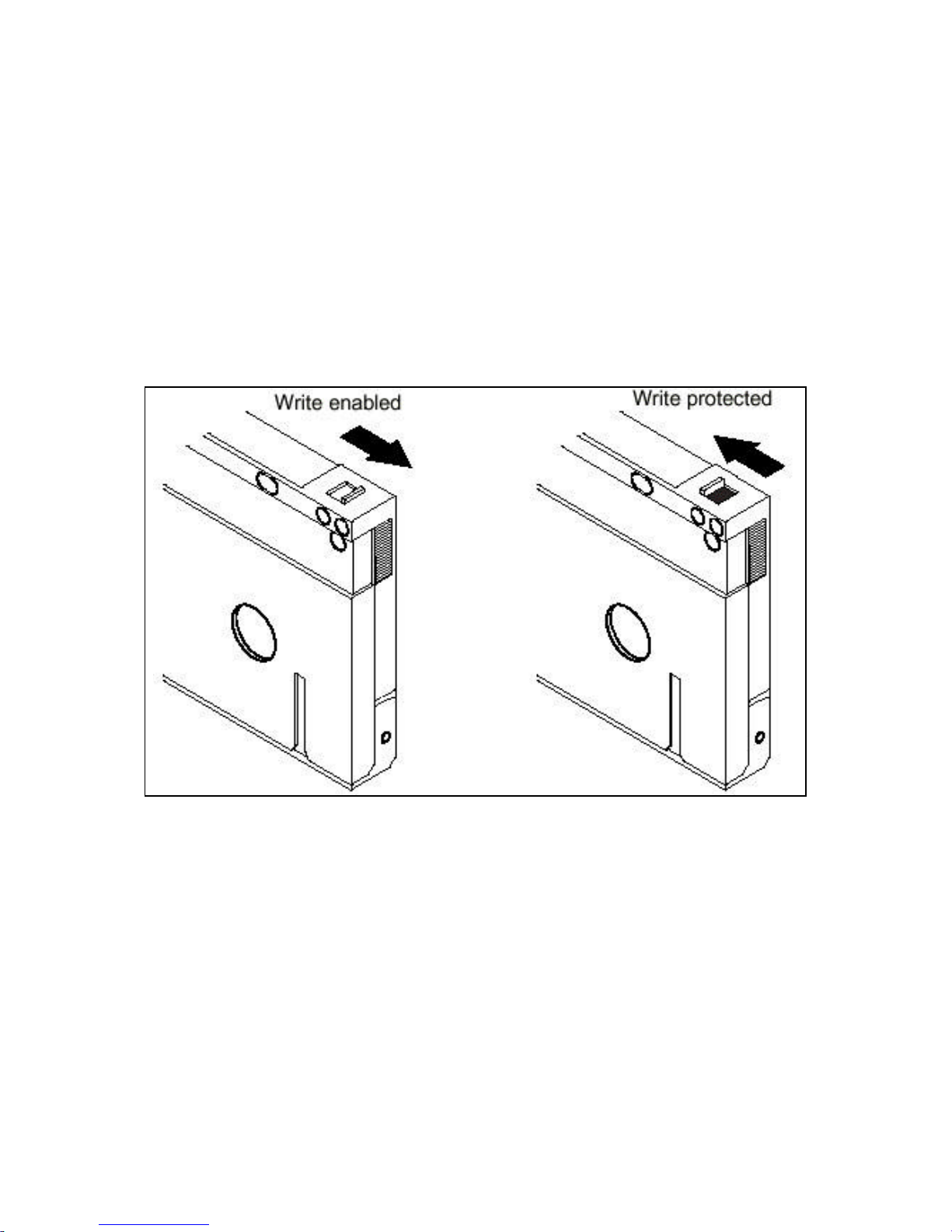
You can write-protect your cartridge by sliding the tab on the top of the
cartridge. In the write-protected state, data can be read from the tape but not
written to. You can only write data to the tape when the tab is in the writeenabled position.
16
LED Codes
The front panel of the LaCie DDS4 drive contains three LEDs: Clean LED,
Media LED and Drive LED. These LEDs provide information about both normal
and error conditions.
Clean LED
The Clean LED functions as follows:
If the Clean LED is ON (lit) continuously, the drive requires cleaning. This
indicates that the drive has been operating for at least 25 hours with DDS1 or
DDS2 media, or for at least 50 hours with DDS3 or DDS4 media.
Page 17

17
If the Clean LED is flashing slowly, the tape cartridge in use has exceeded a
pre-defined soft-error threshold. This signal is a warning only and does not
indicate that data has been lost. If you see this signal, remove the tape at your
earliest convenience and clean the cartridge using an approved DDS cleaning
cartridge (see 2. Getting To Know Your DDS4 Drive for details). If, after
cleaning the drive reinserting the original data cartridge, the Clean LED still
flashes, then you should use a new cartridge for future backups.
Media LED
The Media LED functions as follows:
If the Media LED is ON (lit) continuously, a DDS cartridge has been inserted
and the drive is operating normally.
If the Media LED is flashing rapidly, the drive could not write the tape correctly
(the maximum rewrite count has been exceeded) and the write operation
failed. Clean the drive heads using an approved DDS cleaning cartridge (see
2. Getting To Know Your DDS4 Drive for details). If you reinsert the
original data cartridge and the LED continues flashing, insert a new data
cartridge and retry the operation.
Important Note: As routine maintenance, you should clean the drive
heads after every 25 hours of operation using DDS1 or DDS2 tapes, or
after every 50 hours when using DDS3 or DDS4 tapes.
Drive LED
The Drive LED functions as follows:
If the Drive LED is ON (lit) continuously, the drive is reading and writing the
tape (specifically, there is SCSI or tape activity currently). If you push the eject
button while the Drive LED is ON, you may lose data.
Important Note: If a SCSI Prevent Media Removal command has
been issued, the Drive LED remains ON, and the eject button is
disabled so that the tape cannot be accidentally ejected.
If the Drive LED is flashing rapidly, a hardware fault has occurred. If this
happens immediately after powering on the drive, then the Power-On Self Test
switch is enabled and a Power-On Self Test has failed. The front panel LEDs
may be flashing together. If this occurs, contact LaCie Technical Support. If the
Drive LED is flashing rapidly during drive operation, you should attempt to
remove the tape by pressing the eject button. If the tape does not eject within
2 minutes, press and hold the eject button continuously for more than 5
Page 18

seconds. The tape should eject within 40 seconds. Contact LaCie Technical
Support for more information.
Cleaning the Tape Heads
When to Clean the Tape Heads
If excessive dust or debris from the tape media collects at one or more of the
tape heads, your drive may not be able to read from or write to the tape. To
avoid this problem, you must clean the tape heads in your LaCie DDS4 in the
following circumstances:
After every 25 hours of read/write operation using DDS1 or DDS2 tapes, or
every 50 hours of operation using DDS3 or DDS4 tapes.
If the Clean LED lights up or flashes.
If the Media LED flashes during drive operation.
Important Note: If cleaning the head does not correct a flashing
LED condition, try using a new data cartridge.
18
How to Clean the Tape Heads
To clean the tape heads on your drive, use only a Seagate-qualified DDS
cleaning cartridge (see 2. Getting To Know Your DDS4 Drive for details).
Do not use an audio DAT cleaning cartridge. The drive cannot recognize it.
After you insert the cleaning cartridge, the drive detects that the cartridge is a
cleaning cartridge, then loads and runs the cartridge for about 30 seconds.
When cleaning is complete, the drive ejects the cartridge.
Each time the cleaning cartridge is loaded, a new, unused portion of cleaning
tape is advanced over the entire tape path. The drive does not rewind a
cleaning cartridge. After about 30 cleaning cycles, the entire tape is used up.
In this case, the Clean LED will flash rapidly and the cleaning cartridge should
be replaced.
Automatic Drive Spin-Down and Write
To maximize tape and drive mechanism life, the drive automatically stops the
cylinder when no tape read or write activity occurs.
If a read or write operation occurs, normal operation resumes with no affect
on the host operation.
Page 19

19
If tape Write operations cease, a partially full data buffer may remain. After
one minute with no activity, the drive automatically writes the partial buffer to
the tape. This automatic action minimizes the possibility of lost data if the
power fails.
If data to be written remains in the buffer when the eject button is pushed, the
data is written to tape before the tape is rewound and ejected.
Page 20

20
5. Technical Information
5.1 User Advice When Using SCSI
The following technical information relates to your LaCie DDS4 drive and gives
some practical advice:
Multiple SCSI Devices
External devices must be powered on before booting the computer — even if
they are not to be used. They MUST be left on until the computer has been
shut down.
SCSI basics
This section provides a brief description of the SCSI technology and lays down
a few basic rules for using SCSI peripherals as stand-alone devices or in a
chain.
There are two main categories of SCSI: Narrow SCSI and Wide SCSI.
Narrow SCSI – This is the term used for 8-bit SCSI. You can connect up to 7
peripherals on a narrow SCSI bus. Narrow SCSI peripherals have either 25 or
50 pin connectors.
Wide SCSI – This is the term used to describe 16-bit SCSI. Wide SCSI allows
you to connect up to 15 peripherals on a bus, and also offers higher data
transfer rates than narrow SCSI. Wide SCSI peripherals almost always feature
68-pin connectors.
There are three types of SCSI devices on the market today, which are defined
by the signaling method (the way the signal is transferred over the SCSI bus):
SE, HVD and LVD.
SE (Single-ended) – The most common SCSI interface in use today. Single-
ended uses half of the cable wires for data/control and the other half as a
common ground point. Its advantages include its low cost, and suitability for a
wide variety of applications, including hard drives, CD and DVD drives, as well
as scanners and printers. LaCie Narrow hard drives are single-ended.
HVD (High Voltage Differential) – HVD has three main advantages over
SE: It is possible to have longer overall bus lengths [up to 25 meters (m)],
higher data transfer rates and more devices per bus. However, HVD is a much
more costly solution, is not as widely deployed as SE and is a fading
technology since the advent of Low Voltage Differential.
Page 21
21
Warning! Your LaCie drive is not compatible with HVD devices or
buses! Never connect your LaCie drive to an HVD bus or peripheral.
Doing so may damage your drive and/or system, and will void your
warranty.
LVD (Low Voltage Differential) – This latest addition to the SCSI interface,
which became important with Ultra2 SCSI, combines all of the advantages of
SE and HVD. LVD has rapidly become the de facto standard in highperformance SCSI. Its benefits include increasingly lower cost, more and more
widespread use, enhanced reliability, higher data transfer rates, compatibility
with the newest high-speed hard drives, longer cable lengths than SE (up to
12 m), and backwards compatibility with older SCSI technologies.
The following table shows the different types of SCSI implementations:
Category Narrow (8
bit)
SCSI types Fast SCSI Ultra
Wide (16
bit)
Wide SE
Wide (16
bit)
Ultra2
Wide
Wide (16
bit)
Ultra 160
(LVD)
Wide (16 bit)
Ultra 320 (LVD)
(LVD)
Transfer rate 10MB/s max 40MB/s
max
80MB/s
max
160MB/s
max
320MB/s max
# of devices 8 max 16 max 16 max 16 max 16 max
Cable length 3 m max 1.5 m max 12 m max 12 m max 12 m max
Connectors 25 or 50-pin 68-pin 68-pin 68-pin 68-pin
Fundamental SCSI rules
Follow these seven basic rules when setting up your SCSI peripheral or chain.
1) Give each SCSI peripheral a unique ID number.
Each device in your SCSI chain needs a unique ID number, either from 0 to 6
for Narrow SCSI, or any number between 0-6 and 8-15 for Wide SCSI (ID 7 is
generally reserved for your computer’s SCSI controller). No two devices in the
same chain may have the same ID number, but the order in which the devices
are connected in the bus does not matter. For example, the device with ID 2
could be physically located at the end of the chain, while the device with ID 6
is connected directly to the SCSI port of your computer.
2) Always terminate your SCSI chain.
The last device in your SCSI chain must be terminated. Even if you have only
one SCSI peripheral in your chain, you must terminate it. Single-ended SCSI
devices may have an internal terminator (using an on/off switch) or may
require an external terminator.
Page 22

22
Warning! LVD buses always require external termination; they do not
have internal terminators. Therefore, the last LVD device in a chain
must have an external terminator. Consult your computer supplies specialist
for a terminator that meets your needs.
3) Avoid mixing LVD and SE devices in the same SCSI chain.
For performance reasons, it is important to not mix LVD and SE devices on the
same chain. An all-LVD or all-SE chain will generally perform more reliably
than a mixed chain. While it is technically possible to mix LVD and SE devices
on the same SCSI chain, doing so will limit the performance of all devices on
the chain to SE levels. An all-LVD chain will enable you to achieve the ultrafast transfer rates that LVD has to offer. For more information on mixed SCSI
chains, please refer to 9. Appendix 1 – SCSI Questions and Answers.
4) Respect the maximum allowable cable length for your SCSI
chain.
In order to ensure optimum performance, you must respect the maximum
allowable length for your SCSI chain. The maximum allowable length of the
chain depends on the type of devices (SE, LVD or mixed) connected to it.
Consult the table above, or contact your computer supply specialist for more
details.
5) Never mix HVD devices with SE or LVD devices.
HVD devices require a special controller and are not compatible with LVD or
SE devices. If you connect an HVD device to an SE or LVD device, none of the
devices will work properly. Furthermore, you may damage the devices or your
computer system.
6) Turn on all of your SCSI peripherals before turning on your
computer.
Before turning on your computer, always power on all of the devices in your
SCSI chain. Otherwise, the computer will not recognize the devices. Also,
never leave any unpowered devices in your SCSI chain. If there is an
unpowered device in your chain, the other peripherals may not work correctly
and directory and/or data corruption may occur.
Warning! Always power down the computer before powering off your
SCSI devices. Failure to so can result in the corruption of the hard
drive’s directory.
7) Turn off your computer and SCSI peripherals before
disconnecting them from the chain.
Page 23

Do not disconnect any SCSI peripherals from your computer or chain before
turning off the computer and all of the SCSI devices. Doing so may damage
the peripherals and/or the computer system.
23
Page 24

24
6. Troubleshooting
In the event that your LaCie DDS4 drive is not working correctly, please refer
to the following checklist to find out where the problem is coming from. If you
have gone through all of the points on the checklist and your drive is still not
working correctly, please have a look at the FAQs that are regularly published
on our Web site – www.lacie.com. One of these FAQs may provide an
answer to your specific question. You can also visit the drivers pages, where
the most recent software updates will be available.
If you need further assistance, please contact LaCie Technical Support (see 7.
Contacting Customer Service for details).
The Problem Questions to Ask Possible Solutions
The drive is not
recognized.
Is the SCSI host adapter
recognized correctly by
the Operating System
(OS)?
Windows 98 SE & Me
Users: Go to Start >
Settings > Control
Panel > System >
Device Manager >
SCSI Controller > click
on the plus sign next to
the controller icon, and
you should see your
device listed.
Windows 2000 Users:
Go to Start > Settings
> Control Panel >
System > Hardware tab
> Device Manager
button > SCSI
Controller > click on the
plus sign next to the
controller icon, and you
should see your device
listed.
Windows XP Users: Go
to Start > Control
Panel > Performance
and Maintenance >
System > Hardware tab
> Device Manager
button > SCSI
Controller > click on the
Page 25

25
plus sign next to the
controller icon, and you
should see your device
listed.
Mac Users: Open
Apple System Profiler
and click on the Devices
and Volumes tab. If your
device is not listed,
recheck the cables and try
the other troubleshooting
solutions listed here.
If you cannot see the
device, recheck the cables
and try the other
troubleshooting solutions
listed here.
Is the drive powered up? Check the drive’s power
cable. Make sure the
Power LED is on.
Are both ends of the SCSI
cable connected and
properly seated?
Check both ends of the
SCSI cable. If the drive is
still not recognized, turn
off the computer, then
turn off your peripheral(s).
Disconnect the cables,
reconnect them and turn
on your peripheral(s) and
computer again. If the
drive is still not
recognized, shut down
your computer and try
again.
Has the correct drive
installation procedure
been followed?
Review the installation
procedure described in 3:
Setting Up Your LaCie
DDS4 Drive.
Is there a conflict with Contact LaCie Technical
Page 26

26
other device drivers or
extensions?
Does your computer’s
configuration meet the
minimum system
requirements for use with
this drive?
Are you powering on the
SCSI peripherals before
the computer?
Is the drive’s SCSI ID
number the same as that
of another device on the
SCSI chain?
Support.
Check section 2.1
Minimum System
Requirements.
You must power on all
SCSI peripherals
connected to your
computer before turning
on the computer.
Otherwise, the SCSI
peripherals will not be
recognized.
Check the ID numbers of
all devices in your SCSI
chain and change them if
necessary. Each device
must have an individual
number, i.e. if you had an
external CD-RW, a Hard
Drive and Tape drive
connected on the same
SCSI chain, you would
have the CD-RW ID set at
1, the Hard Drive set at 2
and the Tape drive at 3,
or similar.
Is the terminator on the
drive set correctly?
Are the pins and holes in
the SCSI connectors
straight and not
deformed?
Check the terminator. It
should be attached for an
LVD/Wide drive only if it is
the last device in your
SCSI chain. Otherwise, it
should not be attached.
Turn off your computer
and SCSI peripherals and
check the cables and
connectors. Replace the
Page 27

cables if necessary.
27
The drive is working
slowly.
The LVD drive seems
to be working slowly.
Are you using the correct
SCSI driver?
Is the drive part of a SCSI
chain?
Is the LVD drive connected
to a Narrow SCSI port, or
is part of a mixed LVD-SE
chain?
Make sure you are using
the most recent drivers
supplied by the
manufacturer of the SCSI
card. Contact the SCSI
card manufacturer or
LaCie Technical Support
for more details.
Isolate the drive and see if
performance improves.
If it is, then this drop in
performance is normal.
When connected to
Narrow or SE buses or
chains, the performance
of LVD drives drops to
match the performance of
the Narrow/SE bus. See
Appendix 1 for more
details.
Are you using LVD cables
and terminators?
If you are not using LVD
cables and terminators,
non-LVD cables and
terminators will slow down
the performance of an
LVD drive by constricting
the speed to non-LVD
standards.
Page 28

28
7. Contacting Customer Support
Before You Call Technical Support
1) Read the manuals and review the Troubleshooting section.
2) Try to isolate the problem. If possible, make the drive the only external
device on the CPU, and make sure all cables are correctly and firmly attached.
If you have asked yourself all of the pertinent questions in the troubleshooting
checklist, and you still can't get your LaCie drive to work properly, call us
directly using the number below. Before calling, make sure that you are in
front of your computer and that you have the following information on hand:
1) Your drive's serial number
2) Computer brand and model
3) Operating system and version (Mac OS or Windows)
4) Amount of memory installed
5) Names of CD or DVD drives installed on your computer
6) Names of any other devices installed on your computer
Technical Support Help Hours
LaCie Australia
• Monday through Friday, 9:30AM –
5:30PM EST
Contact Us At:
• (61)2 9669 6900 phone
LaCie Canada
• Monday through Friday, 9:30AM –
5:30PM EST
Contact Us At:
• (416) 530 2545 phone
• (416) 530 2546 fax
LaCie France
• Monday through Friday, 9AM – 5PM
LaCie Belgium
• Monday through Friday, 9AM – 5PM
Contact Us At:
• 32 (0) 2 639 14 71
LaCie Denmark
• Monday through Friday, 9AM – 5PM
Contact Us At:
• 45 70 27 65 43
LaCie Germany
§ Monday through Friday, 9AM – 5PM
Contact Us At:
• 33 (0) 1 69 32 84 23
Contact Us At:
• 49 (0) 211 30 121-111
Page 29

29
LaCie Italy
• Monday through Friday, 9AM – 6PM
Contact Us At:
• 39 02 89 14 09 20
LaCie Netherlands
• Monday through Friday, 9AM – 5PM
Contact Us At:
• 31 (0) 713 326 833
LaCie Spain
• Monday through Friday, 9AM – 2PM,
and 4PM – 7PM
Contact Us At:
• 34 91 323 83 11
LaCie Japan
• Monday through Friday, 9AM – 5PM
Contact Us At:
• 81 3 5733 2205
LaCie Nordic
(Finland, Norway and Sweden)
• Monday through Friday, 9AM – 5PM
Contact Us At:
• 46 (0) 8 411 60 02
LaCie Switzerland
• Monday through Friday, 9AM – 5:30PM
Contact Us At:
• 41 (0) 61 386 80 45
LaCie United Kingdom & Ireland
• Monday through Friday, 9AM – 5PM
Contact Us At:
• 44 (0) 20 7872 0872
LaCie USA
• Monday through Friday, 6AM – 6PM PST
Contact Us At:
• 503-844-4503 phone
• 503-844-4505 fax
Page 30

30
7.1 Warranty
LaCie warrants your drive against any defect in material and workmanship,
under normal use, for the period designated on your warranty certificate. In
the event this product is found to be defective within the warranty period,
LaCie will, at its option, repair or replace the defective hard drive.
This warranty is void if:
• The drive was operated/stored in abnormal use or maintenance conditions;
• The drive is repaired, modified or altered, unless such repair, modification or
alteration is expressly authorized in writing by LaCie;
• The drive was subjected to abuse, neglect, lightning strike, electrical fault,
improper packaging or accident;
• The drive was installed improperly;
• The serial number of the drive is defaced or missing;
• The broken part is a replacement part such as a pickup tray, etc.
• The tamper seal on the hard drive casing is broken.
LaCie will not, under any circumstances, be liable for direct, special or
consequential damages such as, but not limited to, damage or loss of property
or equipment, loss of profits or revenues, cost of replacement goods, or
expense or inconvenience caused by service interruptions.
Under no circumstances will any person be entitled to any sum greater than
the purchase price paid for the drive.
To obtain warranty service, call your LaCie Reseller or LaCie Technical
Support. You may be asked to furnish proof of purchase to confirm that the
drive is still under warranty.
All drives returned to LaCie must be securely packaged in their original box
and shipped with postage prepaid.
Page 31

8. Appendix 1 – SCSI Questions and Answers
For the new user, SCSI terminology can be a little daunting. The table below
was designed to help you get a clearer understanding of what the different
SCSI names mean and their performance characteristics.
Before you read the chart, let’s define what we mean by Standard, Protocol
and Industry names:
• Standard - The broadest category, featuring general guidelines given by the
various industry groups and standards associations. There are three SCSI
standards: SCSI-1, SCSI-2 and SCSI-3.
• Protocols – Sub-categories of SCSI standards with defining specific
characteristics and features. “Narrow” and “Wide”, for example, tell us about
the bus width of a particular type of device.
• Industry names – Names used by computer hardware manufacturers to
describe SCSI devices to potential buyers.
31
Standard
Protocols Industry Names Bus Width
SCSI-1 “Regular” SCSI SCSI-1, SCSI Narrow (8-
bit)
SCSI-2 Wide SCSI
Fast SCSI
Fast Wide SCSI
Wide SCSI-2
Fast SCSI-2
Fast Wide SCSI-2
Wide (16-bit)
Narrow (8bit)
Wide (16-bit)
SCSI-3 Ultra SCSI
Wide Ultra SCSI
Ultra2 SCSI
Wide Ultra2 SCSI
Fast-20 SCSI
Fast-20 Wide
SCSI/Ultra Wide SCSI
Fast-40 SCSI/Narrow
Ultra 2 SCSI
Wide Fast-40
Narrow (8bit)
Wide (16-bit)
Narrow (8-
bit)
SCSI/Ultra 2
SCSI/Ultra2 Wide
Wide (16-bit)
SCSI
Ultra3 SCSI
Ultra 160 SCSI
Ultra 160+ SCSI
Ultra320 SCSI
Fast-80 SCSI
Ultra 160/m SCSI
Ultra4 SCSI/Fast-160
SCSI
Wide (16-bit)
Wide (16-bit)
Wide (16-bit)
Wide (16-bit)
Signaling
Throughput
SE/HVD Up to 5MB/s
SE/HVD
SE/HVD
SE/HVD
SE/HVD
SE/HVD
LVD
LVD
LVD
LVD
LVD
LVD
to 10MB/s
to 10MB/s
to 20MB/s
to 20MB/s
to 40MB/s
to 40MB/s
to 80MB/s
to 160MB/s
to 160MB/s
to 160MB/s
to 320MB/s
What issues are involved when mixing Narrow SCSI and Wide SCSI
devices on the same SCSI chain?
The simplest SCSI configurations use only Narrow devices, or only Wide
devices. In this type of configuration, you choose the correct cable, connect all
of the devices in a bus topology, and place the appropriate type of termination
Page 32

32
at both ends of the bus. In this case, termination is relatively straightforward
because all of the devices have the same width.
Sometimes, however, you may need to mix Narrow and Wide devices on a
single SCSI channel. This is becoming increasingly common as the newest
hard drives are Wide only, but many other kinds of devices are still produced
for the Narrow interface.
The best solution for mixing Wide and Narrow devices is to use a host adapter
that has built-in support for separate segments or channels for Wide and
Narrow devices. Using this sort of host adapter will enable you to set up the
Wide and Narrow devices separately, using a Narrow cable and terminator for
the Narrow segment (or channel), and Wide hardware for the Wide segment
(or channel).
When configured properly, the host adapter handles the mixing of the devices.
This sort of adapter is preferred because Narrow devices generally use singleended signaling, while modern Wide devices require LVD for maximum
performance. The two cannot be mixed on the same bus segment without the
LVD devices dropping down to single-ended mode. Thus, this type of host
adapter enables you to use the LVD devices to their full potential.
If you do not have a host adapter with separate support for Narrow and Wide
devices, you will have to mix them on the same SCSI chain. This more
complicated way of mixing introduces several issues to be taken into account:
• Adapters: You will have to use either a Wide or Narrow cable, depending on
whether the host adapter you are using is Wide or Narrow. Then, whichever
drives are the opposite width, will need an adapter so they fit onto the cable.
For example, if you have a Wide cable connected to a Wide host adapter and
several Wide devices, to add a Narrow device to this chain, you will need an
adapter for the Narrow device to let it plug into the Wide cable. Narrow
devices generally use
25-pin or 50-pin connectors, whereas Wide devices generally use 68-pin
connectors.
• Performance: If you put a Wide device on a Narrow SCSI channel, you will
cut its potential maximum performance, because it will only be able to send
data at the Narrow SCSI channel rate. Conversely, putting Narrow devices on
a Wide channel will not double the Narrow channels performance.
• Device Addressing: Narrow devices cannot see or access device IDs over 7. If
you are going to use Narrow devices on a Wide host adapter, set the host
adapter's device ID to something between 0 and 7, or the device won't work
(we recommend that you leave the host adapter’s ID at 7).
Page 33

33
• Termination: This is the biggest issue with mixing devices. Here is the
problem: when you have a Wide SCSI bus and you connect Wide (16-bit)
devices to Narrow (8-bit) devices, there are an extra 8 data bits present on the
bus. If you just connect the Narrow data signals and leave the Wide signals
"hanging,” then that part of the bus will not be terminated! The same is true
for connecting Wide devices to Narrow buses: many Wide devices, when
connected to a Narrow bus, won't work correctly if the high bits are not dealt
with. As a result, the Wide data signals must be terminated when bus widths
are mixed. Some adapters that are used to mix devices can terminate these
Wide data signals. Connectors that automatically terminate the extra "Wide"
signals include high byte termination. Ask your computer supply specialist for
the adapters that meet your specific needs.
Can I mix Single-ended (SE) devices and Low-Voltage Differential
(LVD) devices on the same SCSI chain?
This is possible, because LVD devices are backwards compatible, meaning
they can be used with SE buses. The LVD devices will simply be reduced to the
maximum speed and cable length limitations of the SE bus.
For example, if you connect an Ultra2 (LVD) Wide hard drive (with a
theoretical maximum throughput of 80MB/s and maximum cable length of 12
m) to an Ultra Wide (SE) bus (whose theoretical maximum throughput is
40MB/s and maximum cable length 1.5 m), the Ultra2 hard drive will operate
in Ultra Wide mode (at a maximum of 40MB/s, with a maximum cable length
of 1.5 m). Therefore, the LVD device will not be used to its full potential.
To add a SE peripheral to an LVD bus and preserve the data throughput and
cable length of LVD, you can use a SCSI expander called an LVD to SE
converter. This converter divides the SCSI domain into two bus segments – one
segment will operate at the LVD data throughput and cable length and the
other bus segment will operate at the single-ended data throughput and cable
length.
What issues are involved when connecting a device using a more
recent SCSI protocol (for example Ultra3) to an older host adapter
(for example, Ultra2)?
In general, when new SCSI protocols are designed they feature backwards
compatibility, meaning that they are compatible with most of the previous
protocols. This case is no exception. An Ultra3 drive attached to an Ultra2 host
adapter will simply operate in Ultra2 LVD mode, with the reduced transfer
rates of Ultra2. If you connect that same Ultra3 drive to an even older host
adapter (SCSI-2, for example), it will simply operate in the fastest mode the
older adapter is capable of handling (Fast-10 SE mode in the case of a SCSI
host adapter) with the cable length limitations of the older host adapter.
Page 34

34
Essentially, the host adapter and drive will negotiate for the best speed that
they both have in common.
What is termination?
SCSI passes signals between devices over SCSI cables that act as transmission
lines. The transmitting device, the cabling and the receiving device must all be
impedance matched in order to accomplish maximum transfer of energy
(signals) from end to end. If not, upon encountering a change of impedance,
part of the signal will be reflected back to the transmitting device. If those
reflected signals arrive at the transmitter after it has switched to the receive
mode, it will think the reflected signal is the signal it is looking for. Not
recognizing the reflected signals will cause that device to issue a SCSI re-send
or perhaps even shut down the bus.
Termination (or terminators) is used to provide a better impedance match,
reducing these reflections to a minimum. Many Single-ended SCSI devices
feature internal termination that works by means of an on/off switch at the
back of the peripheral. Other SE devices may require an external terminator.
LVD peripherals always require external termination. Contact your computer
supply specialist for advice on which type of terminator to use.
Where should I place the terminator?
On external SCSI peripherals, the terminator must be enabled (internal) or
placed (external) on the last device on the bus.
Should I use passive or active terminators?
We recommend that you use active terminators. Passive, single-ended
terminators are okay on a slow SCSI bus (max data throughput of 5Mb/s), but
you are better off using active terminators on all SCSI single-ended
applications.
LVD SCSI devices must have external active terminators.
What are device IDs, priority and arbitration? How do they affect
the performance of the devices in my SCSI chain?
Each SCSI device is addressed on the bus via a specific ID number. For Narrow
SCSI (which allows up to 8 total devices, including the SCSI controller), these
are numbered 0 through 7; for Wide SCSI (16 devices) the numbering is 0
through 15.
The priority that a device has on the SCSI bus is based on its ID number. For
the first 8 IDs, higher numbers have higher priority: i.e., 7 is the highest and 0
the lowest. For Wide SCSI, the additional IDs, from 8 to 15, also have the
highest number as the highest priority; but the entire sequence is a lower
priority than the numbers from 0 to 7. So the overall priority sequence for
Wide SCSI is 7, 6, 5, 4, 3, 2, 1, 0, 15, 14, 13, 12, 11, 10, 9, 8.
Page 35

35
If you have just one SCSI peripheral connected to your computer, priority is
not an issue. The priority levels are used to guide the arbitration process. In a
nutshell, arbitration is the process by which different devices decide which one
can have control of the bus. If more than one device wants control at the same
time, the higher-priority device will "win," while the lower-priority device will
have to wait for its turn.
If you have several peripherals in your SCSI chain, you will typically want to set
the slower devices (scanners, tape drives) to the higher-priority IDs, to ensure
that they are not crowded off the bus by the faster devices. But, if you have
any devices that absolutely cannot tolerate delays in receiving their stream of
data –such as a CD-RW or a video encoder - they should be given top priority
on the bus. Many people also like to make the host adapter the highestpriority device on the bus, which is why host adapters often have a default
SCSI ID of 7.
For even more detailed information on the specifics of SCSI, LaCie encourages
you to visit the following Internet sites:
http://www.scsita.org
http:/www.scsifaq.org
Page 36

36
9. Glossary
Backup – (1) The act of creating at least one additional copy of data onto a
different (and safe) storage device from where it can be retrieved at a later
time if needed. (2) A copy of a file, directory, or volume on a separate storage
device from the original, for the purposes of retrieval in case the original is
erased, damaged, or destroyed.
Bit – The smallest measure of computerized data, either a 1 or a 0. Eight
bits equal one byte, or one character.
Block – A very small section of the storage media comprised of one or more
sectors. A block is the smallest amount of space allocated on a drive for data
storage. By default, a sector of data consists of 512 bytes.
Buffer – RAM cache that is faster than the data that is being delivered.
Buffers are used so data may be stored and delivered to the receiving item as
it is needed.
Bus – Electronic links that enable data to flow between the processor, RAM
and extension cables (peripherals).
Byte – A sequence of adjacent binary digits, or bits, considered as a unit, 8
bits in length. There are 8 bits in 1 byte. See also MB (Megabyte) or GB
(Gigabyte).
Cache, -ing – This is an area of electronic storage (usually RAM) set aside to
store frequently used data from electro-mechanical storage (hard drives,
floppy disks, CD/DVD-ROM, tape cartridges, etc.) Therefore, storing frequently
used data in RAM can enhance your system’s overall response to diskintensive operations significantly.
Configuration – When talking about a PC, configuration is understood to be
the sum of the internal and external components of the system, including
memory, disk drives, the keyboard, the video subsystem and other peripherals,
such as the mouse, modem or printer. The configuration also implies software:
the operating system and various device managers (drivers), as well as
hardware settings and options set by the user via configuration files.
Controller – This is a component or an electronic card (referred to in this
case as a "controller card") that enables a computer to communicate with or
manage certain peripherals. The controller manages the operation of the
peripheral associated with it, and links the PC bus to the peripheral via a
ribbon cable inside the PC. An external controller is an expansion card which
Page 37

37
fills one of the free slots inside your PC and which enables a peripheral (CDROM drive, scanner or printer, for instance) to be connected to the computer.
Cross-platform – Term that refers to a device that is able to be operated by
both Mac and Windows operating systems.
Data Stream – The flow of data that accomplishes a task, usually related to
moving data from storage to computer RAM or between storage devices.
Digital – Discrete information that can be broken down to zero or one bits.
Driver (peripheral manager) – A software component that enables the
computer system to communicate with a peripheral. Most peripherals will not
operate correctly – if at all – if the appropriate drivers are not installed on the
system.
Firmware – Permanent or semi-permanent instructions and data
programmed directly into the circuitry of a programmable read-only memory
or an electronically-erasable, programmable read-only memory chip. Used for
controlling the operation of the computer or tape drive. Distinct from the
software, which is stored in random access memory and can be altered.
Folder – A list created on a disk to store files. Creating folders and subfolders enables you to organize the storage of your files in a logical,
hierarchical manner so that you can find and manage them more easily.
GB (GigaByte) – This value is normally associated with data storage
capacity. Basically, it means a thousand million or a billion bytes. In fact, it
equals 1,073,741,824 bytes (or 1,024 x 1,024 x 1,024).
Hardware – Physical components of a computer system, including the
computer itself and peripherals such as printers, modems, mice, etc.
Host Bus Adapter (HBA) – A printed circuit board that installs in a standard
microcomputer and an interface between the device controller and the
computer. Also called a controller.
Interface – The protocol data transmitters, data receivers, logic and wiring
that link one piece of computer equipment to another, such as a hard drive to
an adapter or an adapter to a system bus. Protocol means a set of rules for
operating the physical interface, such as: do not read or write before the drive
is ready.
I/O (Input/Output) – Refers to an operation, program or device whose
purpose is to enter data into or to extract data from a computer.
Page 38

Kb (Kilobit) – Equivalent to 1,000 bits.
Kb/s – Kilobits per second. 480Kb/s is equal to 60KB/s.
KB (KiloByte) – Basically, this means 1,000 bytes, but it is actually 1,024
bytes.
KB/s – Kilobytes per second. A means of measuring throughput.
Mb (Megabit) – Equivalent to 1,000,000 bits.
Mb/s – Megabits per second. A means of measuring throughput. 480Mb/s is
equal to 60MB/s.
MB (Megabyte) – Basically means one million bytes, but is actually 1,024
Kilobytes or 1,024 x 1,024 bytes, which equals 1,048,576 bytes.
MB/s – Megabytes per second. A means of measuring throughput.
38
Media – The material or device used to store information in a storage
subsystem, such as a tape cartridge, CD, DVD or disk drive.
Operating System (OS) – Software that controls the assignment and use of
hardware resources such as memory, processor time, disk space and
peripherals. An operating system is the basis on which software (applications)
run. Windows, Mac OS and UNIX are among the most common.
Overwrite – To write data on top of existing data thus erasing the original
data.
Peripheral – A generic term applied to printers, scanners, mice, keyboards,
serial ports, graphics cords, disk drives and other computer subsystems. This
type of peripheral often relies on its own control software, known as a
peripheral driver.
Port, hardware – A connection component (SCSI port, for example) that
enables a microprocessor to communicate with a compatible peripheral.
Port, software – A memory address that identifies the physical circuit used
to transfer information between a microprocessor and a peripheral.
RAM (Random Access Memory) – Generally referred to as a computer’s
“memory.” An integrated circuit memory chip that allows information to be
stored and retrieved by a microprocessor or controller. The information can be
Page 39

39
stored or accessed in any order, and all storage locations are equally
accessible.
SCSI (Small Computer System Interface)- Peripheral management
interface, which is independent of the processor. It is capable of managing up
to seven different modules, with constant, high transfer rates.
Seek Time – The amount of time (in thousandths of a second, or
milliseconds) that it takes a hard drive’s read/write head to move to a specific
location n the disk. Average seek, then, is the average of a large number of
random samplings all over the disk. Seek time is CPU independent, meaning
that seek time is the same for a disk drive, whether it is attached to a
computer or not.
Software – In a nutshell, software is a set of instructions for the computer. A
set of instructions to perform a particular task is called a program. There are
two main types of software: system software (an operating system such as Mac
OS or Windows) which controls the operation of the computer and application
software (programs such as Word or Excel) which enable users to perform
tasks such as word processing, spreadsheet creation, graphics, etc.
Storage – In computers, any equipment in which information may be kept.
PCs generally use disk units and other external storage media (diskettes, CDROMs, magnetic disks, etc.) for permanent storage of information.
Termination – A physical requirement of the SCSI bus. The first and last
devices on the SCSI bus must have terminating resistors installed, and the
devices in the middle of the bus must have terminating resistors removed.
Transfer Rate – The rate at which the drive sends and receives data from
the controller. Transfer rates for reading data from the disk drive may not be
the same as the transfer rate for writing data to the disk drive. Transfer rates
are CPU dependent, meaning that regardless of how great a transfer rate your
drive is capable of, the actual transfer rate can only be as fast as the slowest
of your hard drive and computer.
Volume – A desktop mountable storage area, may be a partition of a hard
drive, a removable disk or a cartridge. Typically measured in Megabytes or
Gigabytes.
Utility – Software designed to perform maintenance tasks on the system or its
components. Examples include backup programs, programs to retrieve files
and data on disk, programs for preparing (or formatting) a disk or and
resource editors.
Page 40

40
10. Health, Safety and General Use Precautions
Always follow the basic precautions listed below to use your LaCie drive safely
and correctly. Respecting these guidelines will help to avoid the possibility of
personal injury to yourself or others, as well as to prevent damage to your
device and other computer equipment. These precautions include, but are not
limited to, the following:
Health and Safety Precautions:
• Read this User's Manual carefully, and follow the correct procedure when
setting up the device.
• Do not open your drive or attempt to disassemble or modify it. Never insert
any metallic object into the drive to avoid any risk of electrical shock, fire,
short-circuiting or dangerous emissions. Your drive contains no userserviceable parts. If it appears to be malfunctioning, have it inspected by
qualified LaCie service staff.
• Never expose your device to rain or use it near water or in damp or wet
conditions. Never place containers on it containing liquids that may spill
into its openings. Doing so increases the risk of electrical shock, shortcircuiting, fire or personal injury.
• Make sure that the computer and drive are electrically grounded. If the
devices are not grounded, there is an increased risk of electrical shock.
General Use Precautions:
• Do not expose the drive to temperatures outside the range of 5° C to 45° C
(41° F to 104° F). Doing so may damage the drive or disfigure its casing.
Avoid placing your drive near a source of heat or exposing it to sunlight
(even through a window). Inversely, placing your drive in an environment
that is too cold or humid may damage the unit.
• Always unplug the drive from the electrical outlet if there is a risk of
lightning or if it will not be used for an extended period of time. Otherwise,
there is an increased risk of electrical shock, short-circuiting or fire.
• Use only the power supply shipped with the device.
• Do not place heavy objects on top of the drive or use excessive force on its
buttons, connectors and tray. Doing so increases the risk of damage to the
device.
• Always place your drive in a horizontal position before using it. Otherwise,
it may fall, causing damage to the device and/or corruption or loss of data.
• Protect your drive from excessive exposure to dust during use or storage.
Dust can build up inside the device, increasing the risk of damage or
malfunction.
• Never use benzene, paint thinners, detergent or other chemical products to
clean the outside of the drive. Such products will disfigure and discolor the
front panel and casing. Instead, use a soft, dry cloth to wipe the device.
Important Note: The drive’s warranty may be void as a result of
the failure to respect the precautions listed above.
 Loading...