

Lacanche Sully Installer Manual

Page 1 of 43 – US –
- Do not store or use gasoline or other flammable vapors and
liquids in the vicinity of this or any other appliance.
- WHAT TO DO IF YOU SMELL GAS.
Do not try to light any appliance.
Do not touch any electrical switch.
Do not use any phone in your building.
Immediately call your gas supplier from a neighbor’s phone.
Follow the gas supplier’s instructions.
If you cannot reach your gas supplier, call the fire
department.
- Installation and service must be performed by a qualified
installer, service agency or the gas supplier.
WARNING: If the information in this manual is not
followed exactly, a fire or explosion may result causing
property damage, personal injury or death.
WARNING:
THIS RANGE CAN TIP
INJURY TO PERSONS COULD RESULT
INSTALL ANTI-TIP DEVICE PACKED
WITH RANGE
SEE INSTALLATION INSTRUCTIONS
Fourneau
«Sully»
Lacanche ranges ordered after May 1st, 2015, have the option to be manufactured with a new
minimum chassis height of 36 5/8’’ (930mm) – as well as the default range height of 35 3/8’’
(900mm). Please make note, as this change may impact necessary clearance allowances to
combustible surfaces above the cooktop surface in certain installations requiring permit/occupancy
inspections.

Page 2 of 43 – US –

TECHNICAL DATA
SULLY
Page 3 of 43 – US –
Fig. 1
399 mm*
15 11/
16
’’
838 mm*
33’’
930 mm
36 5/8’’
1405 mm - 55 5/
16
’’
22 mm
1
’’
677 mm
26 5/8 ’’
Fig. 1
2205 mm - 86 13/
16
’’
930 mm
36 5/8’’
1030 mm
40 9/
16
’’
1124 mm
44 1/4 ’’
399 mm*
15 11/
16
’’
838 mm*
33’’
1805 mm - 71 1/
16
’’
930 mm
36 5/8’’
1077 mm
42 3/8 ’’
399 mm*
15 11/
16
’’
838 mm*
33’’
Back spacer
Back spacer
Back spacer
677 mm
26 5/8 ’’
22 mm
1
’’
22 mm
1
’’
677 mm
26 5/8 ’’

TECHNICAL DATA
SULLY
Page 4 of 43 – US –
455 mm
17 15/
16
’’
585 mm
23 1/
16
’’
Back spacer
SULLY 2200
55 mm
2 3/
16
’’
185 mm
7 5/
16
’’
Back spacer
727.5 mm
28 5/8 ’’
650 mm
25 9/
16
’’
800 mm
31 1/2 ’’
SULLY 1800
left
55 mm
2 3/
16
’’
185 mm
7 5/
16
’’
Back spacer
727.5 mm
28 5/8 ’’
650 mm
25 9/
16
’’
800 mm
31 1/2 ’’
SULLY 1800
right
* The range Height is adjustable: 930
mm-36 5/8’’ to 946 mm-37 1/4’’

TECHNICAL DATA
SULLY
Page 5 of 43 – US –
Layout:
Cook’s stoves consisting of a cooking surface above two 62 litre ovens. The work surfaces adjacent to the cooking
surfaces are designed to accommodate one of the optional units in the LACANCHE range or to be used as a worktop
(Figures 1 & 2).
Description:
Cooking surface and body panels:
Enamelled steel or stainless body panels AISI 430. Pressing cooking surface (stainless steel AISI 304) (Figure 2). 3- or 4burners of different size and power individually controlled by a safety valve. Electrical ignition.
TRADITION” model equipped with a 385 x 510 mm (15 5/
32
’’ x 20
5
/64’’) heating plate.
Cook’s stoves consisting of a cooking surface above a two 62 litre ovens and one or two general purpose cabinets
(depending on model) which can optionally be equipped with plate warmers. The work surfaces adjacent to the cooking
surfaces are designed to accommodate one of the optional units in the LACANCHE range or to be used as a worktop.
Gas oven:
Enamelled sheet metal. Dimensions W x D x H: 535 mm (211/16’’) x 465 mm (1819/64’’) x 300 mm (1151/64’’). 3 shelf
level with 70 mm spacing, 69 liters / 2.44 ft3. Heating provided by thermostatically controlled burner, thermocouple
safety cut-outs. Electrical ignition.
Power supply: 120 VAC 60Hz.
Multifunction electric oven:
Dimensions W x D x H: 535 (211/16’’) x 420 (1617/52’’) x 265 (1027/64’’); 68 litres/ 2.40 ft3, 3 shelf level with 70 mm
spacing
Electric grill with a rating of 2850 W
Function static electric oven:
One 1700 W element at the base and a peripheral 1200 W element in the roof which operate simultaneously.
Thermostatically controlled roof and base heating elements, safety cut-out by safety thermostat.
Rating: 2900 W – Power supply: 240 Volts 60Hz.
Function ventilated electric oven:
Heating provided by one circular 2650 W element and one peripheral of 1200 W element..
Thermostatically controlled heating elements, safety cut-out by safety thermostat.
Rating: 2650 W – Power supply: 240 Volts 60Hz.
185 mm
7 5/
16
’’
Fig. 2

TECHNICAL DATA
SULLY
Page 6 of 43 – US –
UF / T
SF
F
Plate warmer cabinet (option SULLY 1800 and SULLY 2200)
Plate warmer-insulated stainless internal lining (AISI 304). Heating provided by 950 W heating element underneath
base. Controlled by thermostat selector switch, 30 to 110 °C. Capacity: 72 plates, Ø 240 mm (9.5’’). Dimensions D x W
x H: 530 mm (20.8’’) x 325 mm (12.8’’) x 490 mm (19.3’’). 5 shelf level with 68 mm (2.8’’).
Rating: 1030 W – Power supply: 240 Volts 60Hz
Accessories:
Per oven: One drip tray, one rack, one pastry tray per oven.
Shipment-Packaging:
Unpack and check the appliance is in good condition. In case damage, note any reservations on the delivery note and
confirm them within 48 hours by registered letter with confirmation of delivery to the carrier.
Appliance
Width
Depth
Height mm
Weight Gross/Net
LG 1432 G
1450 mm / 57.1’’
840 mm / 33.1’’
1070 mm / 42.1’’
200 kg /180 kg – 445 / 400 lb
LG 1832 G
1850 mm / 72.8’’
840 mm / 33.1’’
1070 mm / 42.1’’
275 kg /245 kg – 605 / 540 lb
LG 2232G
2250 mm / 88.6’’
840 mm / 33.1’’
1070 mm / 42.1’’
350 kg /310 kg – 770 / 685 lb
Gas connection:
1/2” ID NPT (Sch 40) inlet, on male coupling (Figures 1 & 2). Sealant on all pipe joints must be resistive to LP gas.
If used, a flex gas line for the gas supply must be metal of at least 1/2” ID NPT approved by an approved certifying
agency (A.G.A., C.G.A., etc.) in compliance with ANSI Z21.41 and Z21.69. Never use a hose made of rubber or other
synthetic material.
Gas supplying:
Appliance gas supplying can be switched, please refer to rating plate and marking at the rear of the appliance.
Electrical connection:
On terminal block at the rear of the appliance. Use flexible cord in accordance with standard N.E.C., AINSI/NEMA 701996 or latest edition (not cord provided) (Figures 1 & 2).
Pressures and hourly consumption:
Appliance gas supplying can be switched (table 1).
Table 1
PRESSURE
6’’ WC
10’’ WC
GAS
Natural Gas
L.P.
Burner
Btu / hr
Btu / hr
Oven
13500
11000
Ultra fast (UF) Tradition (T)
18000
17000
Intensive (I)
15000
13000
Fast (F)
11000
10000
Semi fast (SF)
5000
5000
Page 7 of 43 – US –
Fourneau
«Sully»
INSTALLER'S MANUAL
Appliances must be installed in a workmanlike manner in
accordance with the instructions in this manual and locally
applicable regulations.
This manual will be handed over to the user after
installation.

Page 8 of 43 – US –

INSTALLER’S MANUAL
SULLY
Page 9 of 43 – US –
Cabinet Preparation (SULLY):
Cabinet Preparation (SULLY 1800 - left):
Cabinet Preparation (SULLY 1800 – right – gas option):
A B C D E F G H I J K L M N O
mm
914
330
457
930
290
420
235
405
20
60
765
865
1410
51
660
’’
36
13
18
36 5/8
115/16
165/16
91/4
155/12 13/16
23/8
301/8
341/16
551/2 2 26
A B C D E F G H I J K L M N O
mm
914
330
457
930
290
420
235
405
20
60
765
865
1810
51
660
’’
36
13
18
36 5/8
113/16
165/16
91/4
155/16 13/16
23/8
301/8
341/12
711/4 2 26
Fig. 3 a
A B C D E F G H I J K L M N O
mm
914
330
457
930
690
820
235
405
20
60
765
865
1810
51
660
’’
36
13
18
36 5/8
273/16
325/16
91/4
1515/16 13/16
23/8
301/8
341/16
711/4 2 26
B
A
D
K
G
I C J
E
F
H
L
N
N
O
M
Gas connection
on range
Electrical connection
on range
Place electrical and gas
stub-out in this area
INSTALLER’S MANUAL
SULLY
Page 10 of 43 – US –
Cabinet preparation (SULLY 1800 – right – without gas cooktop option):
Fig. 3
A B C D E F G H I J K L M N O
mm
914
330
457
930
690
820
235
405
420
60
765
865
1810
51
660
’’
36
13
18
36 5/8
273/16
325/16
9 1/4
155/16
169/16
2 3/8
30 1/8
34 1/16
71 1/4 2 26
A N N
Gas
connection on
Electrical connection
on range
Place electrical and gas
stub-out in this area

INSTALLER’S MANUAL
SULLY
Page 11 of 43 – US –
Cabinet preparation (SULLY 2200):
A B C D E F G H
I (a) J K L M N O
Without right gas cooktop option
mm
914
330
457
930
690
820
235
405
420
60
765
865
2210
51
660
’’
36
13
18
36 5/8
273/16
321/4
91/4
1515/16
169/16
23/8
301/8
341/16
87 2 26
With right gas option
A B C D E F G H
I (b) J K L M N O
mm
914
330
457
930
690
820
235
405
20
60
765
865
2210
51
660
’’
36
13
18
36 5/8
273/16
321/4
91/4
1515/16 13/16
23/8
301/8
341/16
551/2 2 26
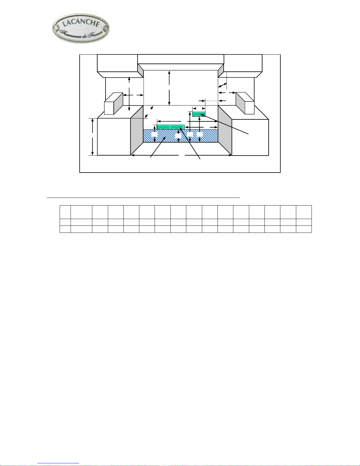
The range is a free standing unit. If the unit is to be placed next to cabinets, the clearances shown in Figure
3a, 3b, 3c, are required.
The range cooktop surface must be no lower than the adjacent base cabinet countertop surface.
Min clearances to combustibles:
0’’ (0 mm) from rear (with spacer installed).
0’’ (0 mm) from sides below countertop surface height.
2’’ (51 mm) from sides above countertop surface height.
Cabinets 13’’ (330 mm) deep may be installed above the range at least 30’’ above the plane of the
cooking surface.
Use range only with factory supplied legs.
Fig. 3 c
B
A
D
K
G
I b
C
J
E
F
H
L
N
N
I a
O
M
Gas connection
on range
Electrical
connection on range
Gas connection
on range
Place electrical and gas
stub-out in this area

INSTALLER’S MANUAL
SULLY
Page 12 of 43 – US –
Before connection:
Check:
- Pipework is perfectly clean in order to prevent the injectors
becoming blocked and malfunctioning of the magnetic heads.
- The gas for which the appliance was set up: Rating plate and
markings.
- Cross-sectional area of gas supply pipework is compatible with the
appliance’s thermal output.
- Provide adequate air supply during use of the appliance.
Gas connection:
Female coupling Ø 15/21, 1/2” ID NPT on A (Figure 4).
After connection:
Check the manifold pressure on pressure connection Ø 15/21, 1/8”
NPT on B (Figure 5, 6).
Change of gas:
The appliance is designed to operate with the gases in Table 2.
Table 2
Country
GAS
Pressure (Pn)
U.S.
Natural gas
6’’ WC
U.S.
L.P. propane
10’’ WC
Fig. 6
B
With gas oven
IMPORTANT
Manual shut-off valve should be installed in an accessible
location in the gas piping external to the appliance for the
purpose of turning on or shutting off gas to the appliance.
A location at the back of an adjacent cabinet is
recommended.
THE APPLIANCE MUST BE INSTALLED IN
ACCORDANCE WITH THE LOCAL CODES OR
National Fuel Gas Code, ANSI Z223.1 or latest edition.
IMPORTANT
Recommended to be installed under an exhaust hood.
In the commonwealth of Massachusetts, the appliance must
be installed by a licensed plumber or gas fitter.
Do not install this unit near combustible walls, partitions,
pieces of furniture or decorative material unless these are
covered by adequate material of the non-combustible type.
Making sure the resulting installation meets fire
regulations.
IMPORTANT
Fig. 4
A

INSTALLER’S MANUAL
SULLY
Page 13 of 43 – US –
Unscrew the screws C near the burner openings (Figures 6 and 7). Pull and raise the top after having loosened the 2
screws D (Fig. 8, CHAGNY and 9, CHAGNY 1400-1800), wedge the cooking surface.
A pressure regulator (fig. 10) is located in the right rear corner under the hob, to gain access to the pressure regulator,
remove the top.
Convertible regulator
The reversible cap is labeled either « LP” or « Nat” and is easily recognized by the raised center screw slot (for
natural) or the center depth (for LP).
To change LP to Natural or vice versa, the seal screw in the regulator lid is unscrewed, reversed and reinstalled to
convert from one setting to another (Figure 12).
Fig. 11
LP Setting
Fig. 12
Nat Setting
Fig. 5
Fig. 9
D
Figure 7
C
C
Fig. 8
Fig. 10
 Loading...