

Page 1

Lacanche Range Cooker
CHAGNY - MACON
(uk)
LG 1053 GE/ EE/ GCT/ ECT
LCF 1053 GE/ EE/ GCT/ ECT - LVTR 1053 EE/ ECT
Chagny - Macon (UK) - Ft 138a - GB - Rév 06 - Modifié le : 07/10/2013 1/42
Page 2

TECHNICAL DATA
—————————————————————————————————————————3
INSTALLER’S MANUAL 7
INSTALLATION / POSITIONING
—————————————————————————————————————————9
GAS CONNECTION
—————————————————————————————————————————11
OPENING AND CLOSING THE HOB
—————————————————————————————————————————12
CHANGING GAS TYPE
—————————————————————————————————————————13
ELECTRIC CONNECTION
—————————————————————————————————————————17
SERVICING / REPAIRS
—————————————————————————————————————————18
ELECTRIC CIRCUIT DIAGRAMS
—————————————————————————————————————————19
GAS CIRCUIT
—————————————————————————————————————————22
USER’S MANUAL 23
CAUTION
—————————————————————————————————————————25
GAS HOB
—————————————————————————————————————————27
SIMMER PLATE (ON TRADITIONAL HOB)
—————————————————————————————————————————29
RADIANT ELECTRIC HOB
—————————————————————————————————————————30
RECOMMENDATIONS BEFORE USING OVENS
—————————————————————————————————————————33
GAS OVEN
—————————————————————————————————————————34
SMALL ELECTRIC OVEN
—————————————————————————————————————————36
STATIC ELECTRIC OVEN
—————————————————————————————————————————37
CONVECTION ELECTRIC OVEN
—————————————————————————————————————————38
CLEANING AND MAINTENANCE
—————————————————————————————————————————39
Information regarding the elimination of electric and electronic waste
—————————————————————————————————————————42
CONTENTS
CHAGNY - MACON
(uk)
Chagny - Macon (UK) - Ft 138a - GB - Rév 06 - Modifié le : 07/10/2013 2/42
Page 3
INSTALLER’S MANUAL
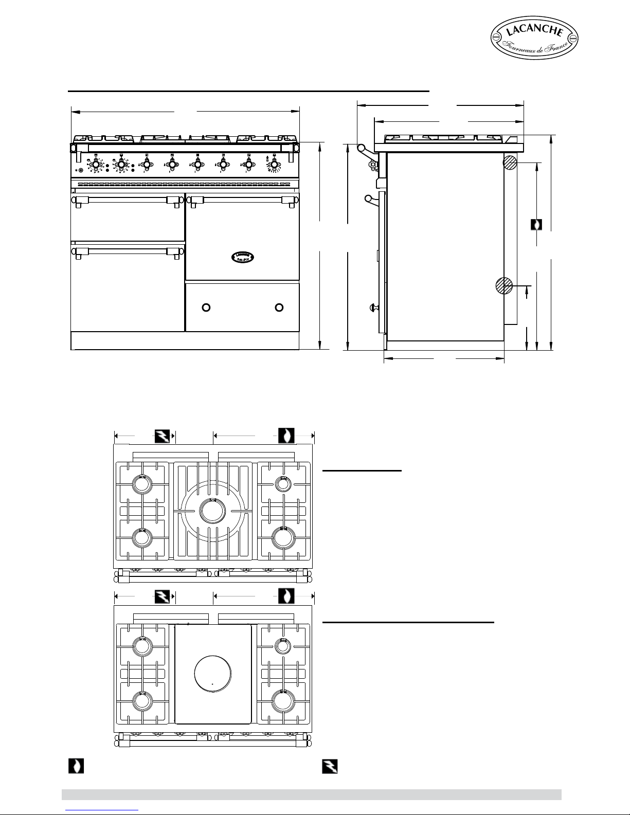
►MACON : TRADITIONAL GAS HOB
5 Gas Burners with simmer plate :
- 5 burners of different size and power (see hob T,
C, D table 1, appendix 0)
- Large cooking zone equipped with a simmer plate
385 x 510 mm.
- Individually controlled by a thermocouple safety
valve.
- Electric push button ignition.
►MACON : CLASSIC 5 BURNER GAS HOB
5 Gas Burners :
- 5 burners of different size and power (see hob A,
C, D table 1, appendix 0).
- Individually controlled by a thermocouple safety
valve.
- Electric push button ignition.
CHAGNY - MACON(uk) CLASSIC AND TRADITIONAL : GAS HOBS
1000
527
815
280
935
725
650
896
900
TECHNICAL DATA
385
C
C
B
D
A
500
C
C
B
D
T
385
500
Gas connection : Tube ∅ 15/21, 1/2” gas thread, on male
coupling
The height of the cooker is adjustable between 900 and 916 mm.
Electric connection, on terminal block at the rear of the appliance
►
Front body panels : Stainless steel or enamelled steel.
► Hob : Pressed stainless steel.
Chagny - Macon (UK) - Ft 138a - GB - Rév 06 - Modifié le : 07/10/2013 3/42
Page 4
INSTALLER’S MANUAL
Gas Oven :
► Enamelled sheet metal.
► Dimensions L x H x P : 400 mm x 305 mm x 405 mm, 55 litre.
► 3 shelf levels with 70 mm spacing in between.
► Thermostatically controlled oven with thermocouple.
► Electric push button ignition.
Power : 3500 W – Supply 230 V 1N~ 50 Hz/ 400 V 3N~ 50 Hz
Static Electric Oven :
► Enamelled sheet metal.
► Dimensions L x H x P : 400 mm x 305 mm x 405 mm, 55 litre.
► 3 shelf levels with 70 mm spacing in between.
► Thermostatically controlled roof (700 W) and base (1500 W) heating elements, safety thermostat.
► Fifted with an electric grill (2100 W).
Power : 2200 W – Supply 230 V 1N~ 50 Hz
Convection Electric Oven :
► Enamelled sheet metal.
► Dimensions L x H x P : 400 mm x 305 mm x 405 mm, 49 litre.
► 3 shelf levels with 70 mm spacing in between.
► The oven is heated by a circular 2650 W element in the back wall, surrounding a fan unit.
► Thermostatically controlled roof and base heating elements, safety thermostat.
► Fifted with an electric grill (2100 W).
Power : 2650 W – Supply 230 V 1N~ 50 Hz/ 400 V 3N~ 50 Hz
Small Electric Oven :
► Enamelled sheet metal.
► Dimensions L x H x P : 400 mm x 145 mm x 440 mm, 25 litre.
► 1 shelf level.
► Thermostatically controlled roof and base heating elements, safety thermostat.
► Fifted with an electric grill (2400 W).
Power : 1500/ 2400 W – Supply 230 V 1N~ 50 Hz/ 400 V 3N~ 50 Hz
Accessories :
Gas Oven : One roasting tray.
One oven rack.
Electric Oven : One roasting tray.
One grill insert with ts into the roasting tray.
One oven rack.
Small Electric Oven : One roasting tray.
One grill insert with ts into the roasting tray.
Pressures and hourly consumption
:
Appliance gas supplying can be switched, please refer to rating plate and marking at the rear of the
appliance (O, T, A, B, C, D : table 3, appendix 0).
Directives :
Gas appliances : 2009/142/CEE.
Low Voltage : 2006/95/CEE.
CEM : 2004/108/CEE.
TECHNICAL DATA
Chagny - Macon (UK) - Ft 138a - GB - Rév 06 - Modifié le : 07/10/2013 4/42
Page 5
INSTALLER’S MANUAL
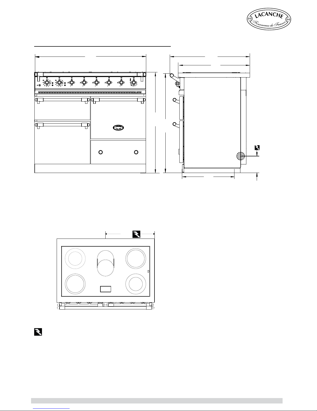
CHAGNY - MACON(uk) ELECTRIC RADIANT HOB
►MACON : ELECTRIC RADIANT HOB
- 5 Radiants Rings of different sizes and power
under a 6 mm glass-ceramic surface (Rings A, B,
C table 2 in appendix 0).
Power : 10600 W – 230 V 1N~ 50 Hz/ 400 V
3N~ 50 Hz
500
B
A
A
B
C
1000
527
725
650
900
150
894
TECHNICAL DATA
The height of the cooker is adjustable between 900 and 916 mm.
Electric connection, on terminal block at the rear of the appliance
►
Front body panels : Stainless steel or enamelled steel.
► Hob : Pressed stainless steel.
Chagny - Macon (UK) - Ft 138a - GB - Rév 06 - Modifié le : 07/10/2013 5/42
Page 6

INSTALLER’S MANUAL
Static Electric Oven :
► Enamelled sheet metal.
► Dimensions L x H x P : 400 mm x 305 mm x 405 mm, 55 litre.
► 3 shelf levels with 70 mm spacing in between.
► Thermostatically controlled roof (700 W) and base (1500 W) heating elements, safety thermostat.
► Fifted with an electric grill (2100 W).
Power : 2200 W – Supply 230 V 1N~ 50 Hz
Convection Electric Oven :
► Enamelled sheet metal.
► Dimensions L x H x P : 400 mm x 305 mm x 405 mm, 49 litre.
► 3 shelf levels with 70 mm spacing in between.
► The oven is heated by a circular 2650 W element in the back wall, surrounding a fan unit.
► Thermostatically controlled roof and base heating elements, safety thermostat.
► Fifted with an electric grill (2100 W).
Power : 2650 W – Supply 230 V 1N~ 50 Hz/ 400 V 3N~ 50 Hz
Small Electric Oven :
► Enamelled sheet metal.
► Dimensions L x H x P : 400 mm x 145 mm x 440 mm, 25 litre.
► 1 shelf level.
► Thermostatically controlled roof and base heating elements, safety thermostat.
► Fifted with an electric grill (2400 W).
Power : 1500/ 2400 W – Supply 230 V 1N~ 50 Hz/ 400 V 3N~ 50 Hz
Accessories :
Electric Oven : One roasting tray.
One grill insert with ts into the roasting tray.
One oven rack.
Directives :
Low Voltage : 2006/95/CEE.
CEM : 2004/108/CEE.
TECHNICAL DATA
Chagny - Macon (UK) - Ft 138a - GB - Rév 06 - Modifié le : 07/10/2013 6/42
Page 7

Lacanche Range Cooker
CHAGNY
MACON
(uk)
INSTALLER’S MANUAL
Appliances must be installed in a workmanlike manner in accordance with the instructions in this manual
and locally applicable regulations.
This manual should be handed over to the user after installation.
Chagny - Macon (UK) - Ft 138a - GB - Rév 06 - Modifié le : 07/10/2013 7/42
Page 8

Chagny - Macon (UK) - Ft 138a - GB - Rév 06 - Modifié le : 07/10/2013 8/42
Page 9

INSTALLER’S MANUAL
CAUTION :
The purchaser undertakes to install or arrange for his/her equipment to be installed in a
workmanlike manner and in accordance with the applicable regulations and standards.
Any servicing or repair work on this appliance must be performed by a qualied engineer.
Never attempt to lift the cooker by holding the hand rails. This will damage the cooker and
invalidate the warrantly.
DELIVERY & PACKAGING
The Cooker is packed in a cardboard carton, and sits on a wooden pallet to which the cooker is
bolted. You will need a 10mm spanner to undo the nuts and bolts attaching the cooker to the pallet.
Carefully remove the cooker from the pallet. NOTE: Never attempt to lift the cooker by holding the
hand rails. This will damage the cooker and invalidate the warranty.
Unpack and check the range is in good condition. In case of damage, note any reservations on the
delivery note and confirm them within 48 hours by registered letter with confirmation of delivery to
the carrier.
PLACING THE COOKER
Allow a minimum clearance of 50 mm between the appliance and any other surfaces (walls affected
by heat).
Line the cooker up with the intended space for it and gently push the cooker backwards into position,
ensuring not to mark or damage the floor. It may be helpful to cover that part of the floor over which
the cooker is to be moved with some sort of covering to protect it, which can be removed once the
cooker is in place.
LEVELLING THE COOKER
In order to level the cooker the plinth needs to be removed. This is done by removing the drawer.
Remove the drawer by opening it, and gently tilting the open front upwards and then lifting the drawer
and rear as well and extracting the drawer. Place the drawer carefully on a protective surface.
Two steel pins attach the plinth to the base of the cooker, running through the top of the plinth and
base of the cooker. These are evident once the drawer has been removed (they look like the top of
nails). Simply pull the two pins out, and carefully remove the steel plinth which should now be loose.
Using the spanner (supplied with cooker in the drawer), the rear and the front of the cooker need to
be leveled in the following way: two bolts will now be evident (exposed by the removal of the plinth).
By winding them clockwise the cooker can be lowered, by winding them anti-clockwise it may be
raised. The left bolt adjusts the rear left corner of the cooker; the right bolt adjusts the rear right of the
cooker. To adjust the front of the cooker, use the larger head of the spanner provided to turn the front
left and front right feet of the cooker, situated just inside the front edge of the corners. Clockwise
lowers the feet, anti-clockwise raises the feet.
BUILDING IN GUIDANCE
→ If the appliance is to be built in between two surfaces, it is CRUCIAL to allow free circulation of
air behind the appliance (provide shielding at rear). Cooktops should NEVER be installed lower
than adjacent worksurfaces. It is also recommended to allow the unit front panel to protrude 50 mm
relative to the adjacent units.
→ The cooker muste be installed under an exhaust hood
.
→ Do not install this unit near combustible walls, partitions, pieces of furniture or decorative material
unless these are covered with adequate thermal insulation of a noncombustible type. Make sure the
resulting installation meets local re regulations.
INSTALLATION / POSITIONING
Chagny - Macon (UK) - Ft 138a - GB - Rév 06 - Modifié le : 07/10/2013 9/42
Page 10
INSTALLER’S MANUAL
①
②
①
②
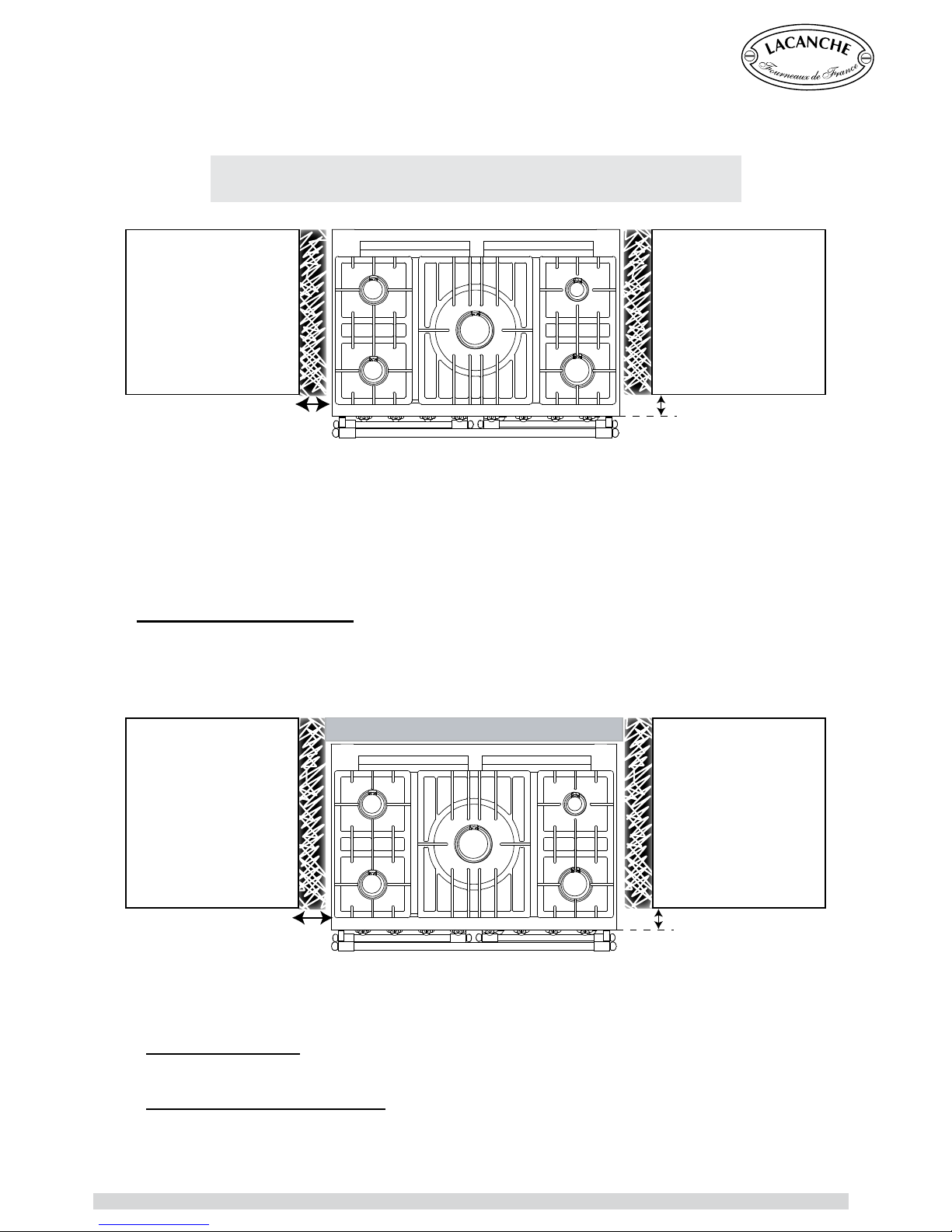
◊ Use of the back in ll panel :
This feature is particularly recommended for built-in ovens as it ensures a 50 mm gap between the
appliance and the wall. It also increases the depth of the hob to 722,5 mm.
Product code : DS 1000.
A shut-off valve must be install and accessible close to the appliance in order to isolate it from the
gas applicable or to facilitate cutting the gas supply : Please ensure that installation complies with
local applicable regulations and standards
- Natural gas supply :
Mandatory to install an Automatic Shut-off Valve (since 1st July 1997 in France)
- LPG supply (butane, propane) :
Propane : Class 1 Safety Expansion Valve.
Butane : Butane safety expansion valve tted to the cylinder (connected to the range by a LPG
approved hose, maximum length 2 metres).
We recommend the front edge of the hob be positioned 50 mm further forward than the adjacent
ttings
. (see below).
If the adjacent parts contain heat-sensitive materials, ensure there is a 50-mm gap between the
side of the oven and the parts in question.
Ensure that the materials adjacent to the lateral panels of the oven are not
ammable.
Back in ll panel
INSTALLATION/ POSITIONING
Chagny - Macon (UK) - Ft 138a - GB - Rév 06 - Modifié le : 07/10/2013 10/42
Page 11
INSTALLER’S MANUAL
Recommendations :
Ensure that the oven is set to the type of gas used (see label on the gas connector).
If the gas supply is not compatible with the gas setting of your range the setting must be modied. Refer
to the “Changing gas type” section of the present instructions.
Butane-fuelled units : Connect unit to 2.6 kg/h pressure reducer. Use two cylinders connected to a 3-way
valve ahead of the pressure regulator in case of prolonged, continuous duty.
Propane-fuelled units : Connect unit to a 3.0 kg/h pressure reducer. Use two cylinders and a 3-way
valve ahead of the pressure regulator in case of prolonged, continuous duty. The use of 37 kg or external
cryogenic tanks is both possible and recommended.
Before connection :
Check :
◊ That the gas supply pressure matches the gas pressure for which the range is set.
◊ Pipework is perfectly clean in order to prevent the injectors becoming blocked and malfunctioning of
the magnetic heads.
◊ The gas for which the appliance was set up : rating plate and markings.
◊ Cross-sectional area of gas supply pipework is compatible with the appliance’s thermal output.
◊ Correct fresh air flowrate (air supply sufcient to enable correct combustion to occur (see appendix 1).
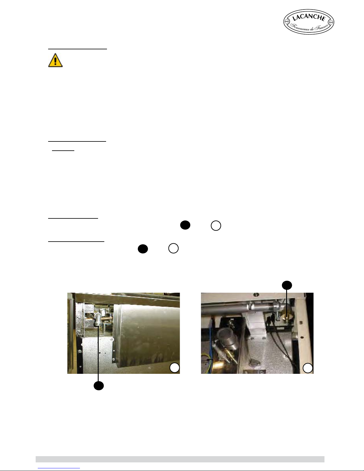
Gas connection :
Male coupling Ø 15/21, 1/2” gas thread on ( see
A
/ figure 1).
After connection :
Check the mains pressure at (see
B
/ figure 2).
Check your connection is gastight.
B
A
1
2
GAS CONNECTION
Chagny - Macon (UK) - Ft 138a - GB - Rév 06 - Modifié le : 07/10/2013 11/42
Page 12
INSTALLER’S MANUAL
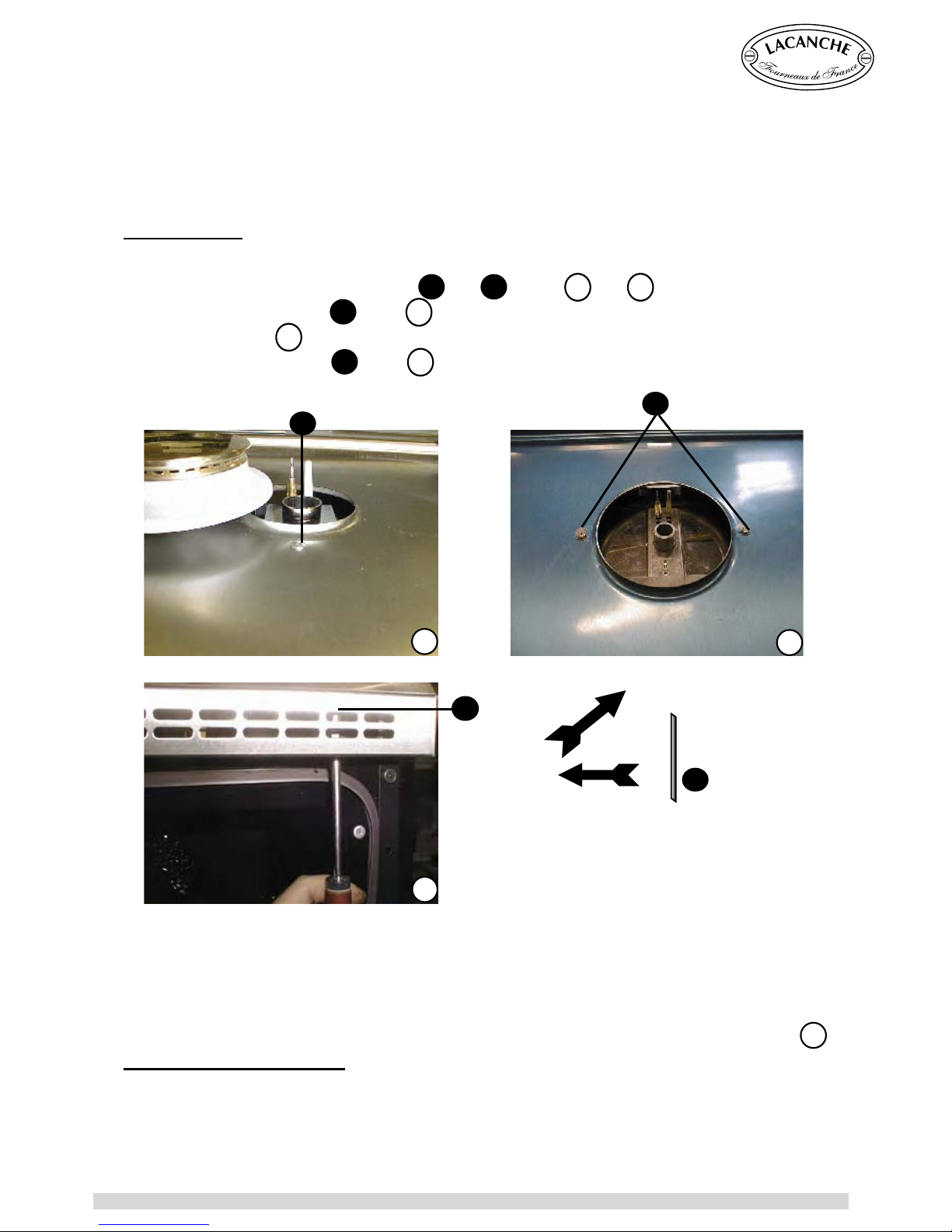
To remove top :
1- Remove the pan racks and burners.
2- Unscrew the screw(s) on burners (see
A
and B figures 1 and 2).
3- Loosen the 2 screws (see
C
figure 3) through the ventilation strip.
4. Lift the hob (figure
4
).
5- Wedge the hob open (see
D
figure 4).
Retting the cooking surface
When refitting the cooking surface, it is vital to tighten the fastening screws. Failure to do so can
cause distortion of the hob top.
It may be necessary to open the hob under the following circumstances :
- Making adjustments when changing gas type.
- Adjusting thermocouples.
- Resetting the safety thermostat on the Radiant. Electric Hob
OPENING AND CLOSING THE HOB
D
C
A
B
1
2
3
4
D
1.Pull foward
2. Lift the table
Chagny - Macon (UK) - Ft 138a - GB - Rév 06 - Modifié le : 07/10/2013 12/42
Page 13
INSTALLER’S MANUAL
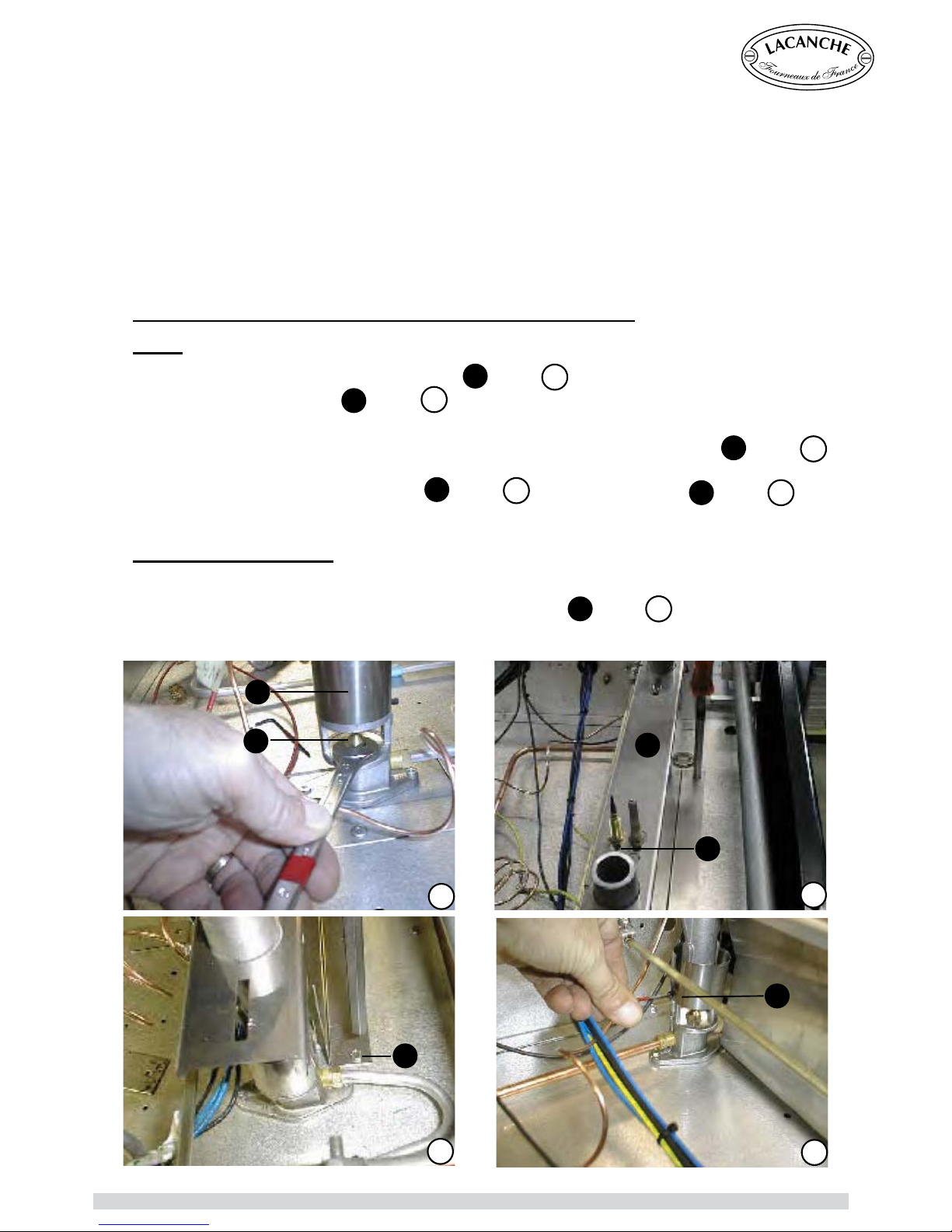
CHANGING GAS TYPE (Changing the Jets on a Gas Cooker)
HOB :
► Lift the air ring up to reveal the injector (see
A
, figure 1).
► Replace the injectors (see
B
, figure 1) in accordance with table 5 in appendix 0 ( Ø in 1/100
mm).
If necessary, the mixer tubes of the lateral burners maintained by a cross-bar (see
C
, figure 2),
may be released.
To release the tubes loosen screws (see
D
, figure 2) and then screw (see E, figure 3).
Note: Ensure that new jet is tted with a new washer, and tighten into place.
Adjusting the primary air :
► Put the burner in place and ignite it.
► Lower the air ring to appropriate level for that gas type (see
F
, figure 4), tabel 6 in appendix 0.
(flame should be crisp, blue without any yellow).
Lacanche ranges are supplied with the appropriate gas tting for the gas type specied when the
order is placed. However, the setting must be ne tuned (COMMISIONED) when the cooker is
installed.
The cooker is designed to operate with the gases in table 4, appendix 0.
IMPORTANT : Close the mains gas valve before carrying out any works.
IMPORTANT
In case of use with a gas other than that for which the cooker was initially set up, it is cru-
cial to replace the injectors and modify the adjustments as dened below.
CHANGING GAS TYPE
wrench, 12
F
1
3
2
B
C
A
E
D
4
Chagny - Macon (UK) - Ft 138a - GB - Rév 06 - Modifié le : 07/10/2013 13/42
Page 14
INSTALLER’S MANUAL
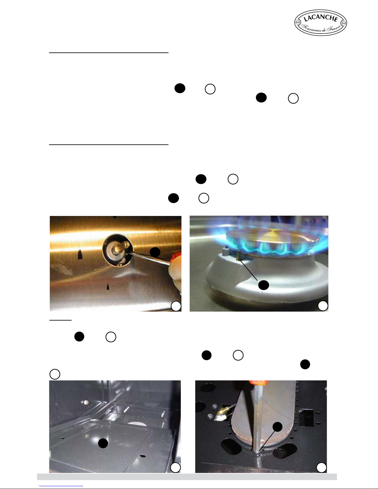
Comissioning (ne tuning) gas burner :
After connection or changing gas type, it is imperative to adjust for a ne tuning.
► Ignite all the burners on the hob.
► After a couple of minutes, reduce to lowest setting.
► Remove control knob by pulling it off (see
G
/figure 5).
► Using a athead screwdriver adjust the simmer ame accordingly (see
G
, figure 5).
Note: The ame is reduced to ¼ when you turn maximum to minimum. Looking for a crisp
blue ame without any yellow which does not go out when turned from maximum to mini-
mum.
Setting the safety thermocouple (Hob) :
If the burner goes out, having kept the control knob pushed in for roughly twenty seconds, check
that :
- The magnetic head grips the valve moderately, nger right.
- The ame touches the point of thermocouple (see
H
, figure 6).
- The thermocouples and magnetic heads are absolutely clean.
Remove control knob by pulling it off (see
H
figure 6).
Using a flathead screwdriver adjust the simmer flame
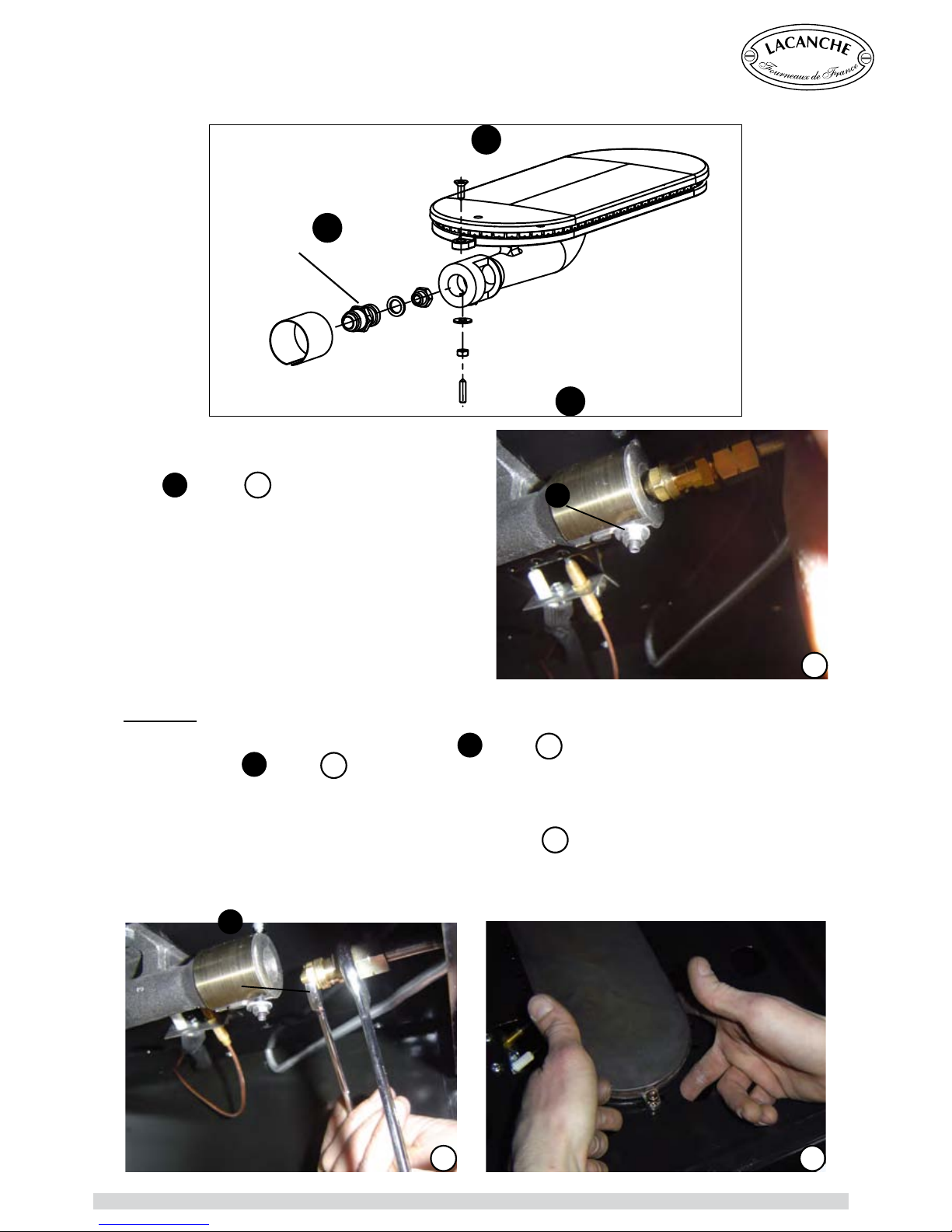
OVEN :
► Open oven door and remove oven base plate by pressing down and backwards and then lifting
out (see I, figure 7).
► Remove drawer.
► Through the drawer aperture, loosen 7mm nut (see
K
, figure.9).
► Remove the 8mm nut and grub screw and washer within it at the front of the burner (see
J
, gure
8
).
CHANGING GAS TYPE
G
5
6
H
7
I
J
8
Chagny - Macon (UK) - Ft 138a - GB - Rév 06 - Modifié le : 07/10/2013 14/42
Page 15
INSTALLER’S MANUAL
CHANGING GAS TYPE
Oven jet :
►With 12mm spanner tted to the injector (see
L
, figure 10) and a 16mm spanner tted to the jet
housing (see L, figure 10) unscrew the jet and remover with washer.
► Replace with the new jet and new washer (see appendix 6, table 0), and tighten.
►Replace burner body, remembering to push it backwards towards the rear of the oven once in
place. Secure with the grub screw, washer and nut. (figure 11).
►Ret the gas pipe into the burner with only the grub screw and nut.
►Loosen the small grub screw inside the nut
(see
K
, figure.9) to release the gas pipe.
Carefully release the gas pipe running through
the air ring into the burner.
►Push the burner downwards and then slide
forwards towards front of oven, then lift the back
of the burner extracting the burner backwards
towards the back of the oven cavity.
Air ring
Injector
Screw
J
Setsrew
K
L
K
9
10
L
11
Chagny - Macon (UK) - Ft 138a - GB - Rév 06 - Modifié le : 07/10/2013 15/42
Page 16
INSTALLER’S MANUAL
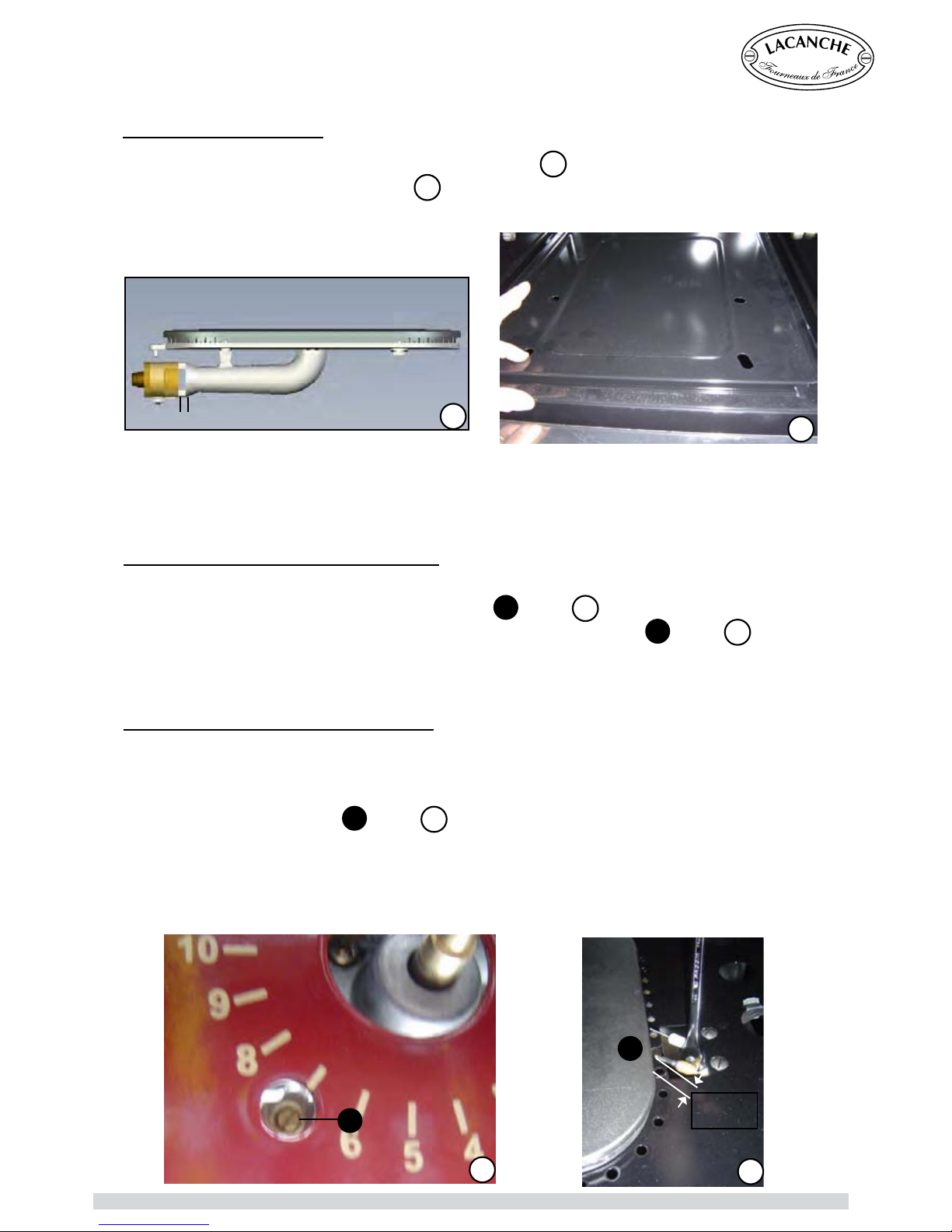
Comissioning (fine tuning) Oven Burner :
► Ignite the oven to Gas Mark 10. Wait for 15 minutes to reach temperature and then reduce to
minimum setting, and remove the control knob (see
M
, figure 14).
► Using a athead screwdriver adjust the simmer ame accordingly (see
M
, figure 14). The hole
allowing access for the screwdriver is located behind Gas Mark 7.
Note : The ame is reduced to ¼ when you turn maximum to minimum. Looking for a crisp blue
ame without any yellow which does not go out when turned from maximum to minimum.
Setting the safety thermocouple (Oven) :
If the burner goes out, having kept the control knob pushed in for approximately twenty seconds,
check that:
- The magnetic head grips the valve moderately, nger right.
- The tip of thermocouple (see
N
, figure 15) should be touched by the ame without coming into
contact with the burner.
- The thermocouples and magnetic heads are absolutely clean.
Looking for a crisp blue ame without any yellow which does not go out when turned from maxi-
mum to minimum.
CHANGING GAS TYPE
3 mm
14
M
15
N
Adjusting the primary air :
> Adjust the airow by moving the adjusting air ring (figure
12
), table n° 7 appendix 0.
> Replace base plate and drawer (figure
13
).
12
13
Adjusting air ring
CAUTION : After connection or changing gas type, it is imperative to adjust for
a ne tuning.
Chagny - Macon (UK) - Ft 138a - GB - Rév 06 - Modifié le : 07/10/2013 16/42
Page 17
INSTALLER’S MANUAL
The cooker must be installed in a workmanlike manner in accordance with the instructions in
this manual and locally applicable regulations. This manual will be handed over to the user after
installation.
Before connection, check :
That the electrical supply of the system is compatible with the voltage and power of the range.
The user’s xed installation must include an all-pole circuit-breaker of approved type.
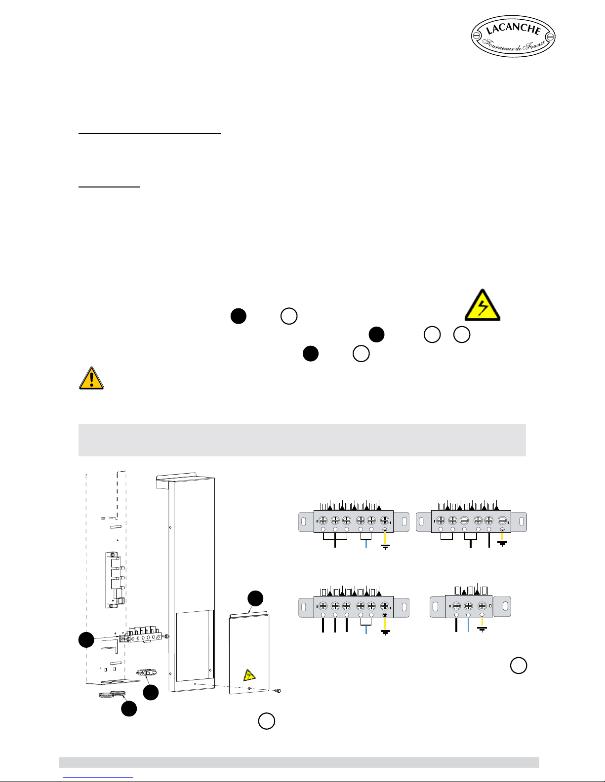
Connection : CAUTION :
- Cable insulation must be type 245 IEC 57 or 245 IEC 66
- The length of the conductors of the power cable between the strain relief device and the terminals
must be such that the conductors become taut before the earth conductor in case of traction on
the cable.
- If this unit is permanently connected to a xed electrical cable, the cable should be equipped with
a fault leak protector.
- If this unit is connected to a wall outlet, the outlet should be permanently accessible.
- Remove cover ( or covers) (see
A
/ figure 1), to the back of the unit identified by .
- Use a standard flexible cable to connect to terminal block (see
B
/ figures 1 & 2).
- Secure the cable by means of cable clamp (see
C
/ figure 1).
It is hazardous to put the appliance into service without connecting it to suitable ground.
ELECTRIC CONNECTION
L N
1 2
400 V 3N ~ 50 Hz 230 V 1N ~ 50 Hz
230 V 1N ~ 50 Hz 230 V 3 ~ 50 Hz
L1 NL2 L3
1 2 3 4 5
N L1 L2 L3L
1 2 3 4 5 1 2 3 4 5
The supply of three phase 400 without neutral is not possible
No liability can be accepted for accidents resulting from non-compliance with this
requirement or incorrect grounding.
1
2
A
C
B
D
Chagny - Macon (UK) - Ft 138a - GB - Rév 06 - Modifié le : 07/10/2013 17/42
Page 18
INSTALLER’S MANUAL
All work on or repair of an appliance must be carried out by a qualied engineer.
Greasing gas valve ( Hobs a n d O vens)
:
The valve may lose its grease through use. It is therefore necessary to grease the valve in order to
make it leaktight and facilitate turning.
1 - Shut off the valve and / or the main electrical supply of the unit.
2 - Take out the knob corresponding to the gas valve to be greased.
3 - Unscrew the head from the body of the burner valve.
4 - Grease the tap shaft (high temperature lubricant, for example : SILICAL GEL ™ BARBAHL).
Caution ! Any excess grease should be removed.
Reverse operation 3 to 1 (in that order) to put valve and knob back on.
Electric Limiting thermostat :
In accordance with the construction regulations, the limiting thermostat is intended to protect the
range from overheating.
In the event of overheating the limiting thermostat is triggered and cuts out the range’s oven
functions.
The advanced technology used in the limiting means that it is very sensitive to impacts and
vibration that may occur during transport and handling.
The limiter may therefore be unexpectedly triggered when the oven is first heated and stop the
oven from working.
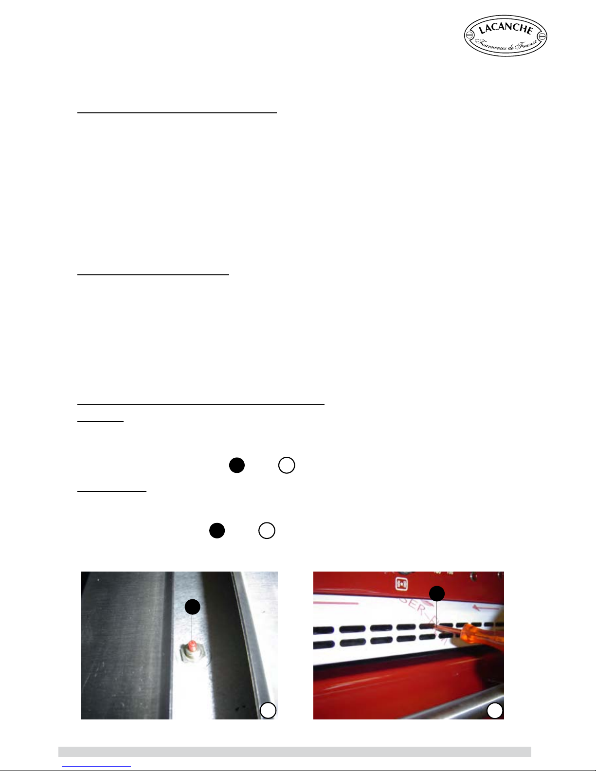
To reset limiting thermostat for electric ovens with :
Gas hob :
1-
Remove the ventilation strip from the rear of the hob.
2-
Unscrew the cover protecting the knob.
3-
Press the knob marked (see
A
/ figure 1).
Electric hobs :
The button is behind the ventilation strip .
To have access there, it is necessary to use a small screwdriver to press on the push-button and
reset limiting thermostat (see
B
/ figure 2).
SERVICING / REPAIRS
1
2
A
B
Chagny - Macon (UK) - Ft 138a - GB - Rév 06 - Modifié le : 07/10/2013 18/42
Page 19
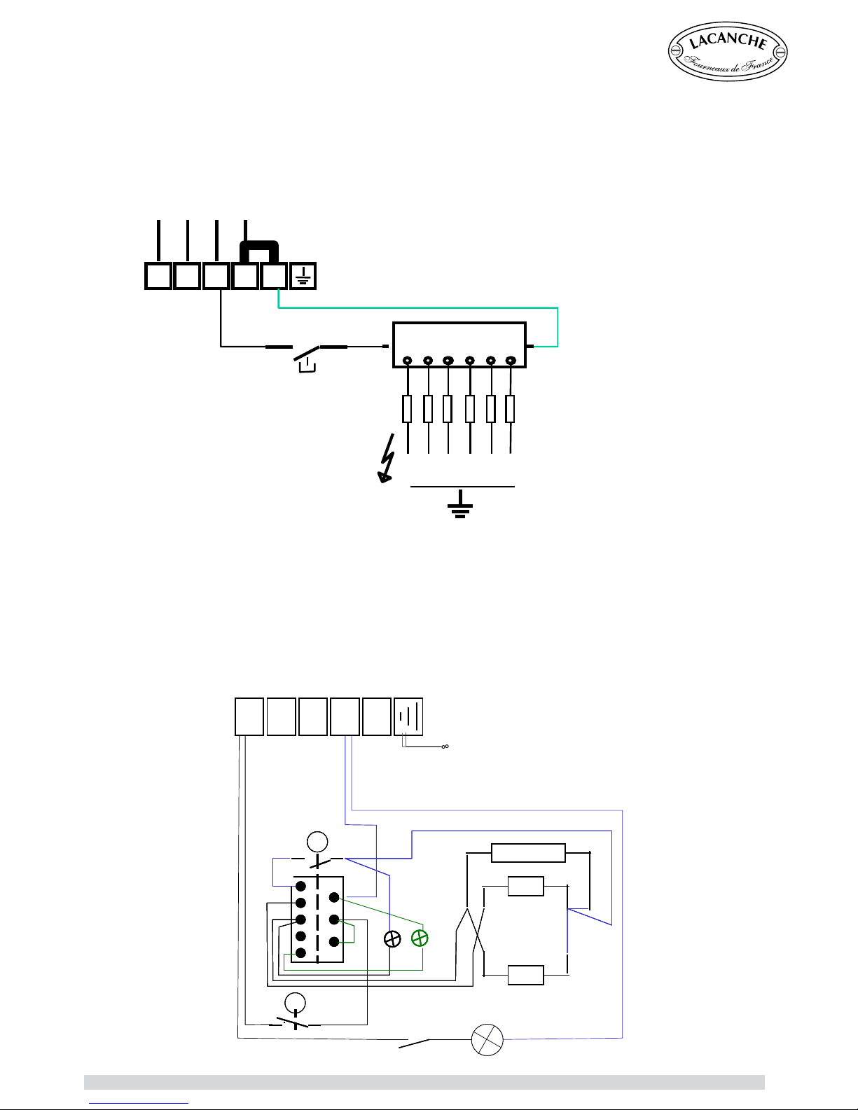
INSTALLER’S MANUAL
For references and descriptions of the various components refer to table 9 in appendix 0
Note: Ignition controller terminal lugs not in use are to be grounded.
1 2 3 4 5
L1 L2 L3 N
12345
6
A
B
& B1
S
1
X
ELECTRIC CIRCUIT DIAGRAMS
Gas Hob + Gas Oven (Ignition)
Static Electric Oven
LE
N2N1
L3L2L1
P2
P1
P3
4
3
1
2
5
H4
H1
TH
TL
SCE1_005/A
L
Mr
X1
S
R14
R16
Chagny - Macon (UK) - Ft 138a - GB - Rév 06 - Modifié le : 07/10/2013 19/42
Page 20
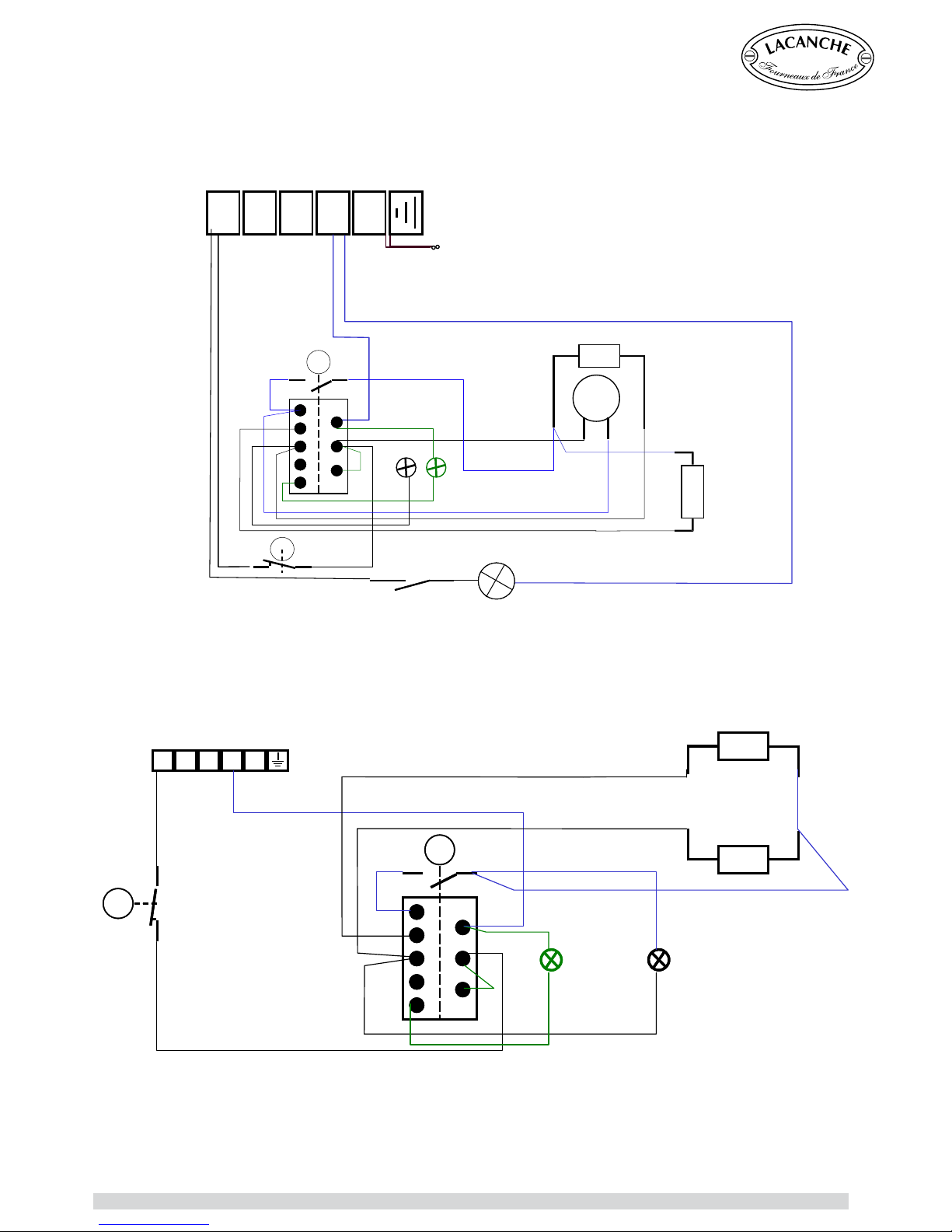
INSTALLER’S MANUAL
ELECTRIC CIRCUIT DIAGRAMS
P2
P1
P3
4
3
1
2
5
P2
P1
P3
4
3
1
2
5
1 2 3 4 5 1 2 3 4 5 1 2 3 4 5
SCE1-017
TH
TL
H4
H1
R16
R9
Small Electric Oven
LE
N2N1
L3L2L1
N2N1
L3L2L1
P2
P1
P3
4
3
1
2
5
SCE1_007/A
H4
H1
TH
TL
L
Mr
X1
S
R15
M
R14
Convection Electric Oven
Chagny - Macon (UK) - Ft 138a - GB - Rév 06 - Modifié le : 07/10/2013 20/42
Page 21
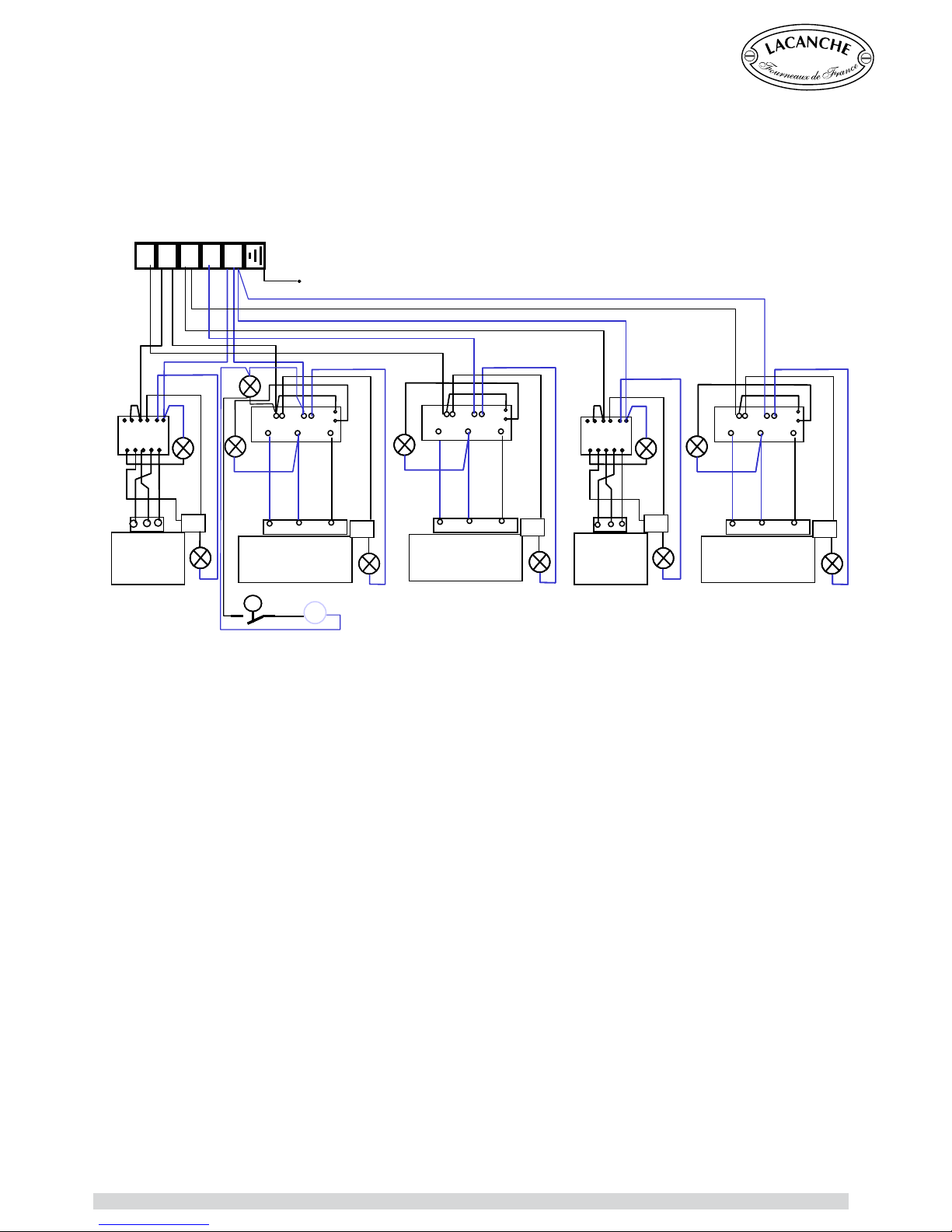
INSTALLER’S MANUAL
ELECTRIC CIRCUIT DIAGRAMS
Radiant Electric Hob
N2N1
L3L2L1
LE
2
S
P1
H
3 1
4
P3 P1 P2
2 1 3 45
2
S
P1
H
2
S
P1
H
24
4A
P1 P2 Pilot
4A 4 2
S1
S2
S
H
2
S
P1 H
RV1 ’
(simple)
3 1
4
P3 P1 P2
2 1 3 45
2
S
P1 H
2
S
P1 H
P3 P1 P2P3 P1 P2
RV2 ’
(double)
24
4A
P1 P2 Pilot
4A 4 2
S1
S2
S
H
24
4A
P1
P2 Pilot
4A 4 2
S1
S2
S
H
RV3
(ovale)
24
4A
P1 P2 Pilot
4A 4 2
S1
S2
S
H
24
4A
P1
P2 Pilot
4A 4 2
S1
S2
S
H
H
S
B
RV1
(simple)
Crd
H
S2
RV2
(double)
Crd
H
SB
RV1
(simple)
Crd
H
S2
RV2
(double)
Crd
H
S2
RV3
(ovale)
Crd
H
TT
TD
Chagny - Macon (UK) - Ft 138a - GB - Rév 06 - Modifié le : 07/10/2013 21/42
Page 22
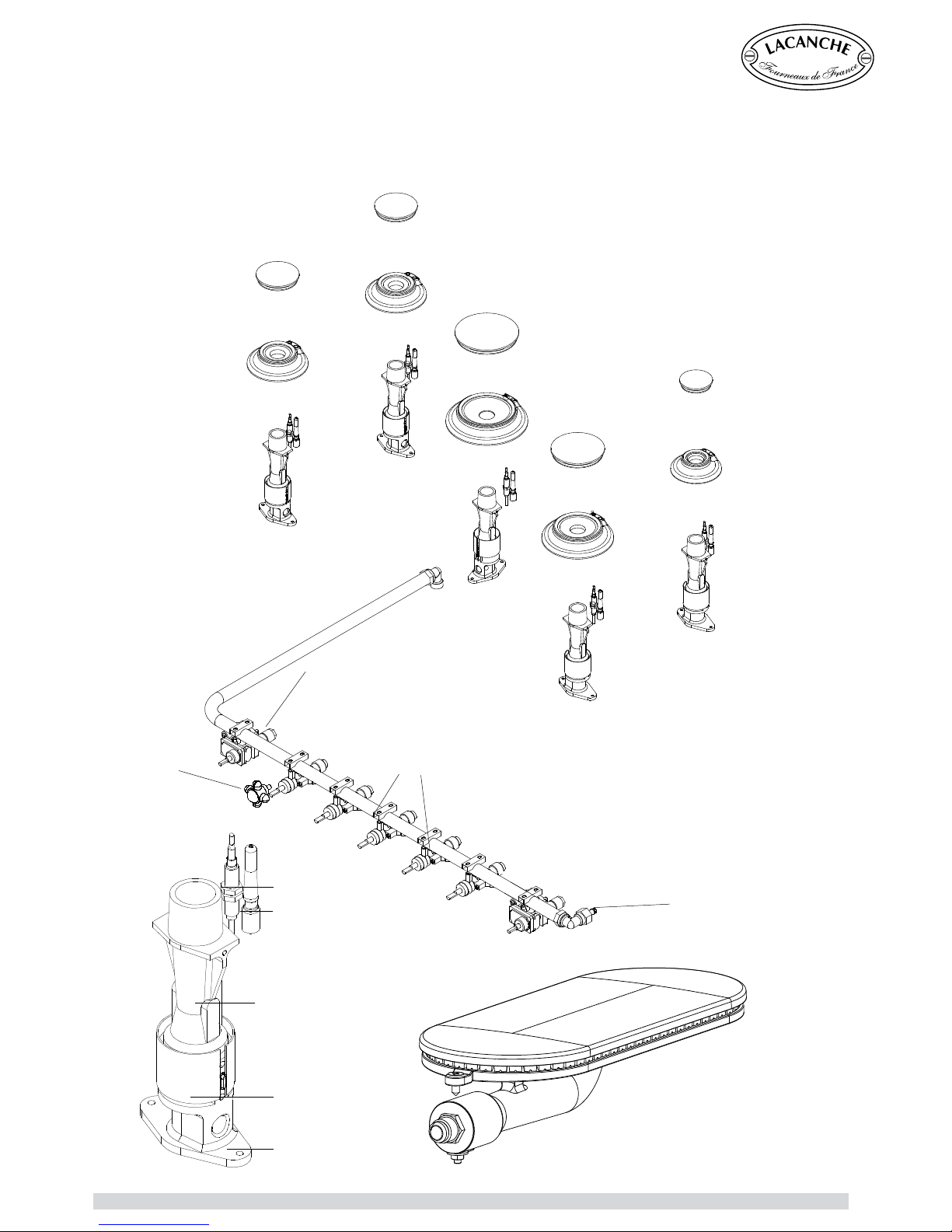
INSTALLER’S MANUAL
90 000 003
65.033018
65.080005
1,5 kW = 65.064007
3,0 kW= 65.064007
4,0 kW= 65.064007
5,0 kW= 65.064007
65.39895
65.226006
88.064012
65.330006
65.640004
65.330008
65.640006
65.330007
65.330005
65.640003
65.640005
65.330008
65.51110
65.640004
65.330006
65.32638
For references and descriptions of the various components refer to table 10 in appendix 0
GAS CIRCUIT
Chagny - Macon (UK) - Ft 138a - GB - Rév 06 - Modifié le : 07/10/2013 22/42
Page 23
Lacanche Range Cooker
MACON
USER’S MANUAL
IMPORTANT
It must be installed in accordance with the applicable regulations and standards in an adequately
ventilated room.
Any changeover to a gas other than that for which the cooker is set up must be carried out by a qualied
installer.
Any changeover to a voltage other than that for which the cooker is set up must be carried out by a qualied
engineer.
WARRANTY
The warranty is stated on the sales contract. Please contact your approved Dealer if any work has to be
carried out under warranty.
This warranty excludes damage resulting from incorrect installation, improper use or inadequate servicing.
Chagny - Macon (UK) - Ft 138a - GB - Rév 06 - Modifié le : 07/10/2013 23/42
Page 24

USER’S MANUAL
This range has the marking, i.e. it meets the essential requirements of the Euro-
pean safety directives to which it is subject.
CAUTION
—————————————————————————————————————25
GAS HOB
—————————————————————————————————————27
SIMMER PLATE (ON TRADITIONAL HOB)
—————————————————————————————————————29
RADIANT ELECTRIC HOB
—————————————————————————————————————30
RECOMMENDATIONS BEFORE USING OVENS
—————————————————————————————————————33
GAS OVEN
—————————————————————————————————————34
SMALL ELECTRIC OVEN
—————————————————————————————————————36
STATIC ELECTRIC OVEN
—————————————————————————————————————37
CONVECTION ELECTRIC OVEN
—————————————————————————————————————38
CLEANING AND MAINTENANCE
—————————————————————————————————————39
Information regarding the elimination of electric and electronic waste
—————————————————————————————————————42
USER’S MANUAL
CHAGNY - MACON
(uk)
Chagny - Macon (UK) - Ft 138a - GB - Rév 06 - Modifié le : 07/10/2013 24/42
Page 25

USER’S MANUAL
This appliance is not for use by children. If unfamiliar with this appliance, use should
be overseen by a competent person who has read all the relevant information.
Before use, it is mandatory to remove all the internal and external plastic packing,
failure to do so will cause irreversible damage to the steel walls of the cooker.
Never store flammable products in the oven, cabinet, plate-warmer or on the table.
Flammable materials can catch fire, plastic items may melt or ignite and other
types of items could be ruined items in other materials may be damaged.
Never hang / store any ammable products above the appliance, to avoid risk of
re.
The oor covering of the room in which the range is to be tted must be capable
of withstanding temperatures 65°C greater than ambient temperature without
distorting, shrinking or fading. This range must not be tted on a carpet or plastic
oor covering.
Do not obstruct the flow of combustion or ventilation air to the appliance. Be sure
a fresh air supply is available.
Do not use aluminum foil to line any part of the oven or on the hob.
Do not hang articles from any part of the appliance or place anything against the
oven to avoid risk of re or degradation of material (e.g.melting).
This appliance is for cooking. Based on safety considerations, never use the oven
or hob to warm or heat a room. Also, such use can damage the hob or oven parts.
Do not hang articles from any part of the appliance or place anything against the
oven to avoid risk of re or degradation of material (e.g.melting).
When using the hob, do not touch the burner grates or the immediate surrounding
area. Areas adjacent to the burners may become hot enough to cause burns.
When using the cooker, accessible parts may be hot. It is recommended children
stay strictly away from the cooker at all times.
Monitor the children to be sure they don’t play with the cooker.
Children should not be left alone in the kitchen while the range is in use. Do not
store items of interest to children over the unit. Children climbing to reach items
could be seriously injured.
When using the oven, do not touch the interior surfaces of the oven, the exterior
area immediately surrounding the door. The range gets hot during use. Do not
touch heating elements inside the oven.
Disconnect from power supply before servicing.
If appliance is installed on a base, take precautions to prevent appliance sliding
off the base.
After any use, to close the valve and cut off gas supply.
Always be sure to disconnect the cooker from the mains electricity supply when
replacing the oven light.
This appliance is not made to be used in conjunction with any type of external
timer or separate control system
Never attempt to lift the cooker by holding the hand rails. This will damage the
cooker
CAUTION
Chagny - Macon (UK) - Ft 138a - GB - Rév 06 - Modifié le : 07/10/2013 25/42
Page 26

Chagny - Macon (UK) - Ft 138a - GB - Rév 06 - Modifié le : 07/10/2013 26/42
Page 27
USER’S MANUAL
►
►
►
►
Highly valued by chefs because of their fast heating and ease of use, gas flame burners have always
been traditional heat sources for cooking in large kitchens. Other heat sources have appeared in
recent years but just as many users still prefer gas. It offers many advantages; gas provides a
fast increase in temperature. The height of the flame can be checked easily at a glance in order to
increase or reduce its power. Accessories such as wok rings and simmer & griddle plates may be
GAS HOB
Lacanche gas hobs for cook’s stoves are fitted with burners of different power. These automatically
stabilised flame burners offer a very low slow setting to facilitate simmering or high heat for quick
sealing. Depending on their rating, they are suitable for various types of utensils.
Semi fast burner : is recommended for small sauceboats, small saucepans or blini pans for example.
A trivet can be placed on the pan support to provide greater stability for smaller pans.
Fast and intensive burners : are ideal for shallow frying pans, saucepans and cooking pots. Their
high output provides very fast increases in temperature and very flexible use.
Ultra fast burner : is a high-power burner. It is especially recommended when using large pans and
woks for dishes that have to be sealed quickly (fricassees, fritters, grilled meat).
You will quickly learn how to use the various types of burners to achieve optimum cooking.
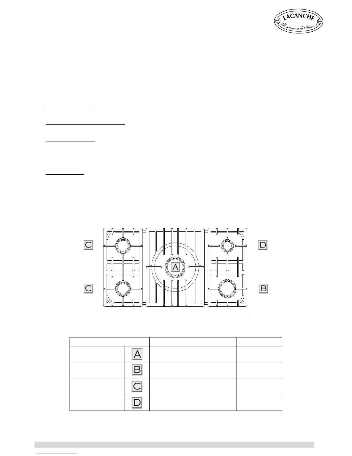
Description :
The burners are arranged on a stainless steel hob in various configurations depending on the model
(See Figures below). Each burner is fitted with a thermocouple safety cut-out.
This device switches off the gas supply if the flame is accidentally extinguished.
The various types of burners can be identified by their respective diameter.
Designation Diameter of the burner cap Power
Ultra fast
Ø 107 mm 5 kW
Intensive
Ø 90 mm 4 kW
Fast
Ø 72 mm 3 kW
Semi fast
Ø 55 mm 1,5 kW
Chagny - Macon (UK) - Ft 138a - GB - Rév 06 - Modifié le : 07/10/2013 27/42
Page 28
USER’S MANUAL
GAS HOB
Use :
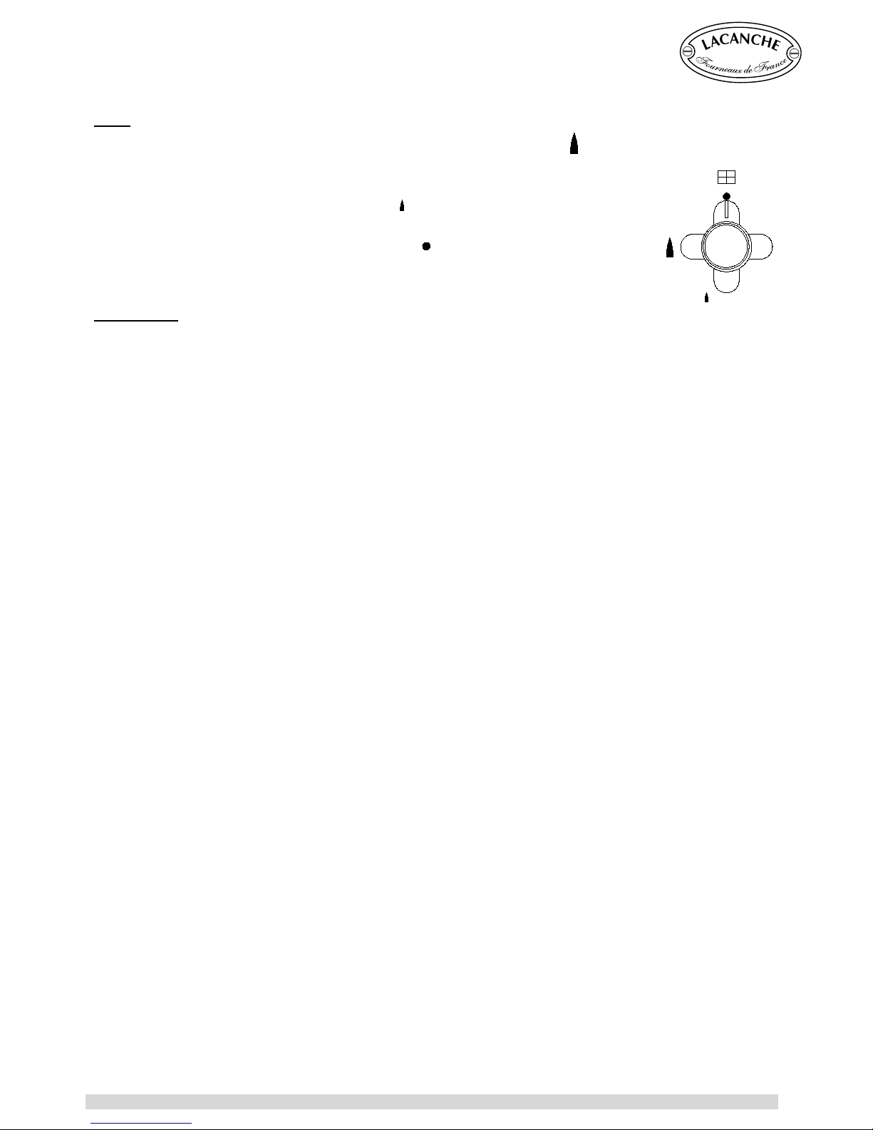
Simultaneously press in and turn the burner dial anti-clockwise to setting
.
Press the ignition button while maintaining pressure on burner dial for about 20 seconds
to ignite burner and initialise safety thermocouple.
A reduced flowrate position identified by the
mark produces the preset minimum
burner power (low flame).
To turn off, turn the control knob clockwise to the «
» position.
The control knob returns to its initial position, the latching mechanism operates and the
gas safety cut-out is activated several seconds after the burner goes out.
Useful hint
Always choose a burner that matches the diameter of the utensil used.
CAUTION : During use of the cooking surface, accessible parts may become very hot during use.
Warn users of the potential risks.
Chagny - Macon (UK) - Ft 138a - GB - Rév 06 - Modifié le : 07/10/2013 28/42
Page 29
USER’S MANUAL
►
►
►
►
The simmer plate is an enamelled cast iron plate heated by a high-power gas burner. It can be used
as a work surface and several saucepans can be placed on it at the same time.
Using the traditional hob (simmer plate) is ideal for cooking larger pots (jam, pans, fish & ham
nettles) or for using a matter of pans at once over the large cooking area.
The center ring is the hot part and the heat differencies from here across the simmer plate : it is
therefore cooker towards the edges, where you might leave a pot simmering / holding.
By removing the central round disc, the burner below can be used as a conventional open burner.
The Lacanche wok ring sits in place of the central disc, for use with a wok for stir or frying.
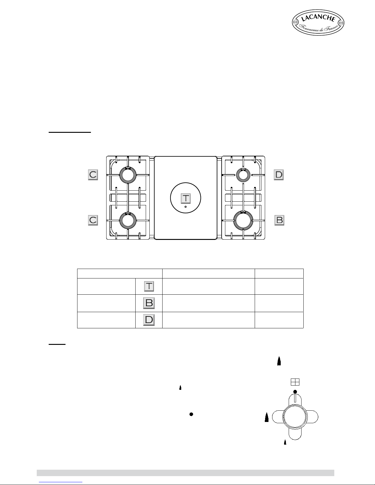
Description :
The heating plate is made entirely of enamelled cast iron. It consists of two parts, the main part rests
directly on the cooking surface and the other removable plug part is located in the middle of the plate.
SIMMER PLATE (ON TRADITIONAL HOB)
CAUTION: Temperature may exceed 300 °C.
Warn users of the potential risks.
Designation Diameter of the burner cap Power
Ultra fast
Ø 107 mm 5 kW
Intensive
Ø 90 mm 4 kW
Semi fast
Ø 55 mm 1,5 kW
Use :
Remove the centre from the simmer plate by means of the lever rod provided.
Simultaneously press down onto and turn the burner dial anti-clockwise to setting
.
Press the ignition button while maintaining pressure on burner dial for about
20 seconds to initialise safety
A reduced flowrate position identified by the
mark produces the preset
minimum burner power (low flame).
Replace the centre piece.
To turn off, turn the control knob clockwise to the «
» position.
The control knob returns to its initial position, the latching mechanism
operates and the gas safety cut-out is activated several seconds after the
burner goes out.
Do not use water to clean the simmer plate when it is hot. This
can damage it.
Chagny - Macon (UK) - Ft 138a - GB - Rév 06 - Modifié le : 07/10/2013 29/42
Page 30
USER’S MANUAL
The principle of the ra diant electric hob is relatively simple. It involves placing a heat source,
generally an electric element, underneath a glass-ceramic surface, that is capable of withstanding
high temperatures.
Radiant hotplates provide very fast temperature increases and controllability. This feature is useful
for all dishes that require rapid variation in the rate of heating.
The atness of radiant hobs ensures good stability and reduces the risk of pans tipping over. They
are also particularly easy to maintain.
Description :
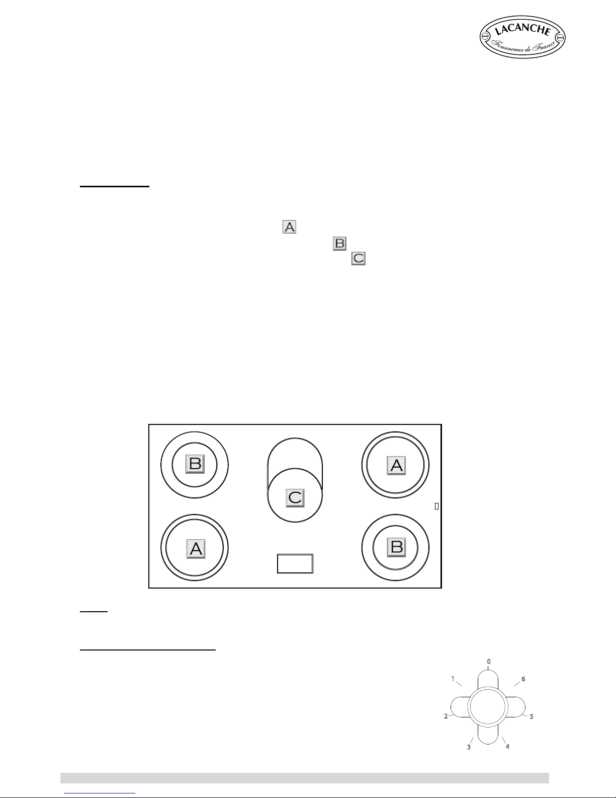
The electric radiant hob comprises a 6 mm thick vitroceramic plate equipped, according to the model,
with the following:
- a 2100 Watt, single-circuit hotplate Ø 210
.
- a 1000/2100 Watt, double-circuit hotplate Ø 140/210
.
- a 1400/2200 Watt, double-circuit oval hotplate 170 x 264
.
The single plate is controlled by a 6-position selector switch. The dual plate has an inner 1400 W
circuit controlled by a power control and an external 700 W circuit controlled by an additional selector
switch.
The double-circuit hob comprises a 1100 W internal circuit controlled by a heating power controller
and an external 1000 W circuit controlled by an additional selector switch.
The oval hob comprises a forward 1400 W circuit controlled by a heating power controller and a rear
800 W circuit. Activating the additional selector switch brings the total power of this hob to 2200 W.
Note : All the hobs are equipped with an after-heat warning light. The warning lights come on several
seconds after the appropriate hob has been switched on and go out when the heat of the hob drops
below approximately 70°C.
RADIANT ELECTRIC HOB
Use :
Select the control knob for the chosen hotplate, the adjacent indicator lamp is lit.
Single plate (Ring A, 2100 W) :
Start cooking in position 6 depending on the quantity to be cooked and reduce
the setting according to the type of cooking required.
The various positions are best suited to the following examples of cooking
operations:
1 & 2 = Keeping food warm or preparing sauces.
3 & 4 = Gentle simmer or maintain cooking.
5 & 6 = Boiling and sustained high simmer
1
2
3
4
5
6
0
Chagny - Macon (UK) - Ft 138a - GB - Rév 06 - Modifié le : 07/10/2013 30/42
Page 31
USER’S MANUAL
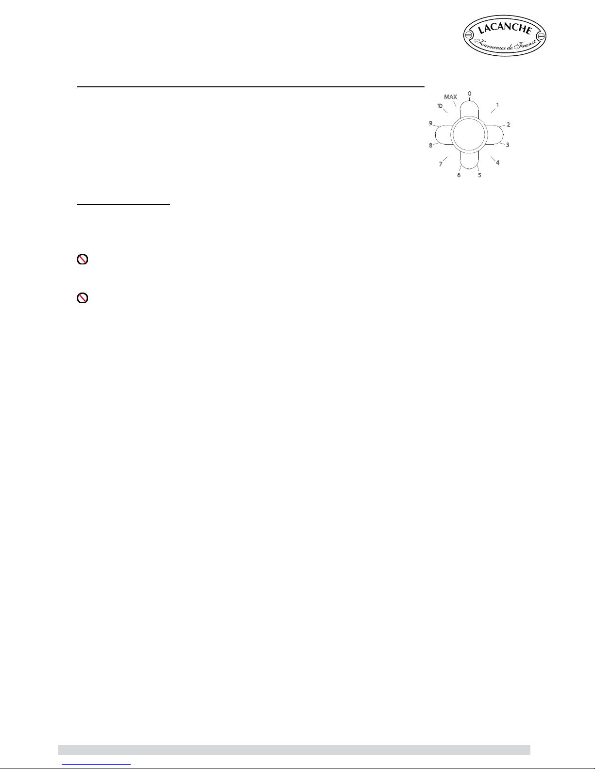
Double-circuit hob (Ring B, 1000/ 2100 W & Ring C, 1400/ 2200 W) :
Set the heating power controller to position 10 then, when the elements is redhot, reduce the heat to the position required for cooking.
To obtain maximum power from the double element, set the knob to the MAX
position.
Bring the knob back to a position between 1 and 10 to regulate the overall
temperature of the hob.
To switch the additional circuit off 0.
Recommendations
Use pots having a slightly concave smooth base in order to avoid scratching the hotplate.
Make sure the size of the utensil is appropriate for your requirements. The diameter of the utensil
base must be he same or slightly greater than that of the screen printing on the hotplate.
Never place or leave an empty enamelled or aluminium utensil on a heat source. Similarly, do not
place products wrapped in aluminium foil directly on the hob as this can cause permanent damage
to your appliance.
Avoid spilling sugar or syrup splashes, remove them immediately because they can cause small
chip marks.
Never apply more heat than can be absorbed by the food: too much heat causes loss of water,
grease and wastes energy.
Whenever the recipe permits, cover your pans with pids in order to save energy.
Remember to return the control knob to O shortly before the end of cooking because the accumulated
heat will complete the cooking.
CAUTION :
If any surface crack appears, immediately insolate the appliance from the mains and
contact your installer.
0
1
2
3
4
56
7
8
9
10
MAX
RADIANT ELECTRIC HOB
Chagny - Macon (UK) - Ft 138a - GB - Rév 06 - Modifié le : 07/10/2013 31/42
Page 32

Chagny - Macon (UK) - Ft 138a - GB - Rév 06 - Modifié le : 07/10/2013 32/42
Page 33

USER’S MANUAL
Designed to help you enjoy the best performance from your ovens.
To ensure you use the oven under optimal conditions and to its best advantage please read the following
recommendations which will undoubtedly improve your understanding of the principles of oven cooking.
An oven cooks and heats by using a heat source which is generally located inside the oven. This heat
source heats the air and then the entire oven. The food therefore cooks thanks to the heat given off by the
heating elements but also thanks to heat radiated from the oven walls.
A few preliminary recommendations :
Before using the oven for the first time, heat it while empty to the 220°C position on the thermostat
for approximately 2 hours to heat the rockwool oven insulation and burn off the grease used in the
manufacturing process. All odours and smoke will disappear when the oven has been used a few times.
Oven dishes :
The material of which cookware is made influences cooking due to its thickness, ability to transmit heat
and its colour.
¤ Aluminium, earthenware and aluminium with a non-stick coating reduce cooking and underside browning.
These materials are recommended for cooking cakes and roasts.
¤ Enamelled cast iron, anodised aluminium, tin-plated iron, ovenproof glass, heat-resistant porcelain and
aluminium with a non-stick coating and coloured exterior increase underside browning. These materials
are recommended in particular for open tarts, quiches and all crispy preparations that must be browned on
the underside as well as on the top.
Cooking recommendations :
We advise you :
→ Pre-heat the oven for 10 to 12 minutes depending on the setting selected before placing your dish in
the oven.
→ When placing the dish in the oven, make sure that it is not too close to the oven walls in order to prevent
the edges of dishes being exposed to excessive radiated heat.
→ Not to place dishes directly on the oor of the oven or to cook meat directly in the dripping pan
.
→ To use dishes that retain considerable heat (earthenware or enamelled cast iron) with high sides, whose
measurements are in proportion to the piece of meat to be roasted and to turn red meat over half way
through cooking to prevent smoke from the grease that is given off when meat is cooked
→ Place the drip tray at the bottom of the oven in order to collect any spillages when cooking fruit tarts.
Using the grill on electric ovens :
CAUTION : the grill cooks very quickly, always keep an eye on the food you are cooking.
→ Lightly oil the surface of meat and sh before placing them on the sliding grid.
→ Only place and use the drip tray under the oven rack in order to collect cooking juices and prevent
spillages in the case of cheese dish.
→ The grill is either on or off. You do not change its temperature. To adjust the speed of cooking or
grilling, change the level of the food in the oven raising it closen to or futher from the grill as required.
→ Keep oven door closed when using in grill mode, except to chek food cooking.
Using there tips, we recommend that you try cooking some simple & different dishes to
help you get the feel of your oven.
RECOMMENDATIONS BEFORE USING OVENS
Chagny - Macon (UK) - Ft 138a - GB - Rév 06 - Modifié le : 07/10/2013 33/42
Page 34
USER’S MANUAL
The gas oven is a high temperature oven with a minimum temp of 160 °C, and a strong bottom heat.
It is ideal for high temp cooking such as roasting, sealing joints, poultry, pizzas, soufés, ect ...
The strong bottom heat is useful for joint roasting (e.g. poraties); it is vital to turn food during the
cooking process.
We recommend to use of electric ovens for dishes that have to be cooked in a dry atmosphere or at
very low temperatures (below 160°C) such as meringues and certain cakes and pastries.
In addition, gas oven are ideal for cooking all dishes that require high “bottom heat”.
Bottom heat is obtained through heat from the lower part of the oven, i.e. in the case of a gas oven,
the location where the heat source is situated. Bottom heat is recommended for cooking fruits tarts,
quiche lorraines, etc...
Description :
Made of sheet steel with an acid-resistant enamel coating applied at 850 °C. The gas ovens have 3
shelf positions (70 mm spacing) allowing shelves and flatware to slide in easily.
The dimensions of oven ares : 400 mm x 305 mm x 405 mm, 55 litre.
The oven burner is controlled by an thermostat valve. A thermocouple safety cut-out switches off the
gas supply to the thermostat valve if the burner is accidentally extinguished.
The oven burner is a large unit in order to ensure even heating of the base surface area. Its thermal
output is 3,5 kW.
The gas oven is supplied equipped with one roasting tray and one
oven rack as standard.
Use :
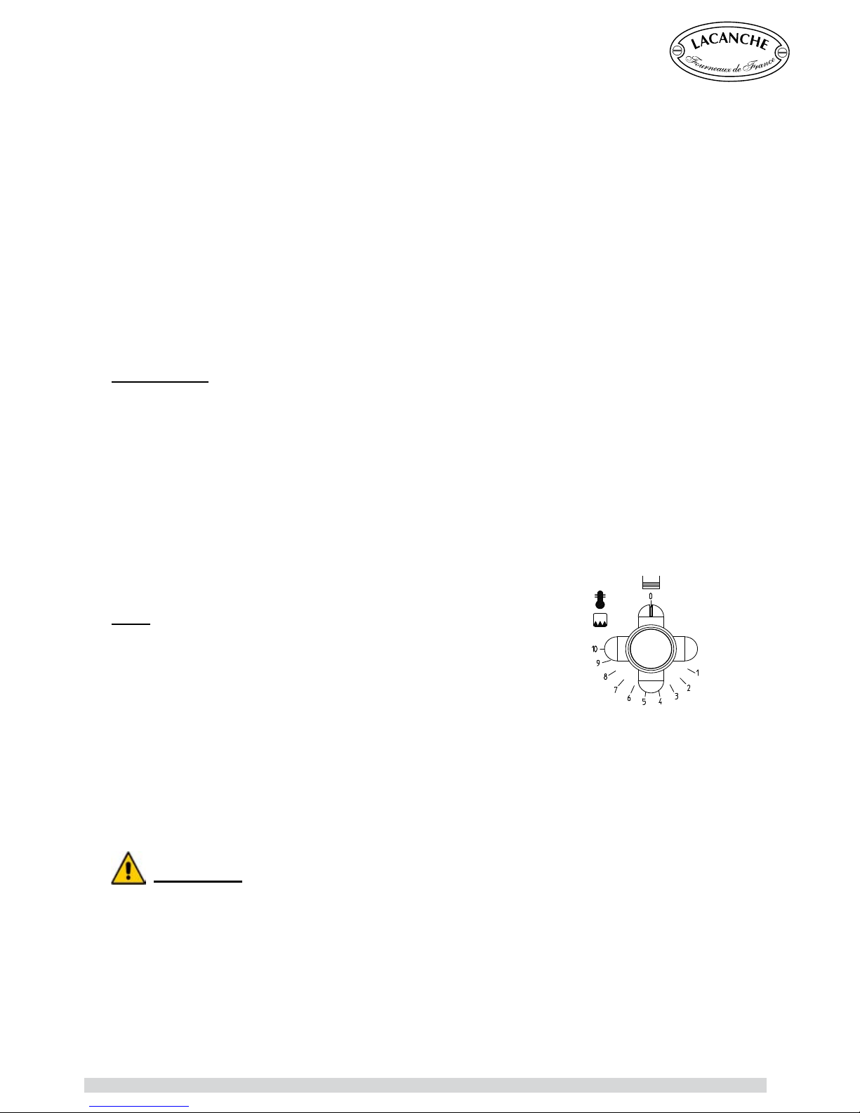
Press and set the oven thermostat dial anti-clockwise to position
10 while pressing the ignition button.
Keep the control knob pushed in for roughly 20 seconds until the
safety thermocouple is activated.
To turn off, turn the control knob clockwise to the O position. The control knob returns to its initial
position, the latching mechanism operates and the gas safety cut-out is activated several seconds
after the burner goes out.
GAS OVEN
CAUTION :
- When the oven are switched on, accessible parts may become very hot. Keep children
away from them. Be careful when handling dishes and oven rack.
- Openings or slits for ventilation or heat dissipation must not be blocked.
- Never store ammable products in the compartment for saucepans.
Chagny - Macon (UK) - Ft 138a - GB - Rév 06 - Modifié le : 07/10/2013 34/42
Page 35
USER’S MANUAL
GAS OVEN
Useful hints : see paragraph “Recommendations before using ovens”
Item
Temperature °C / Gas
oven
1 160 °C
2 165 °C
3 180 °C
4 195 °C
5 210 °C
6 225 °C
7 240 °C
8 255 °C
9 270 °C
10 285 °C
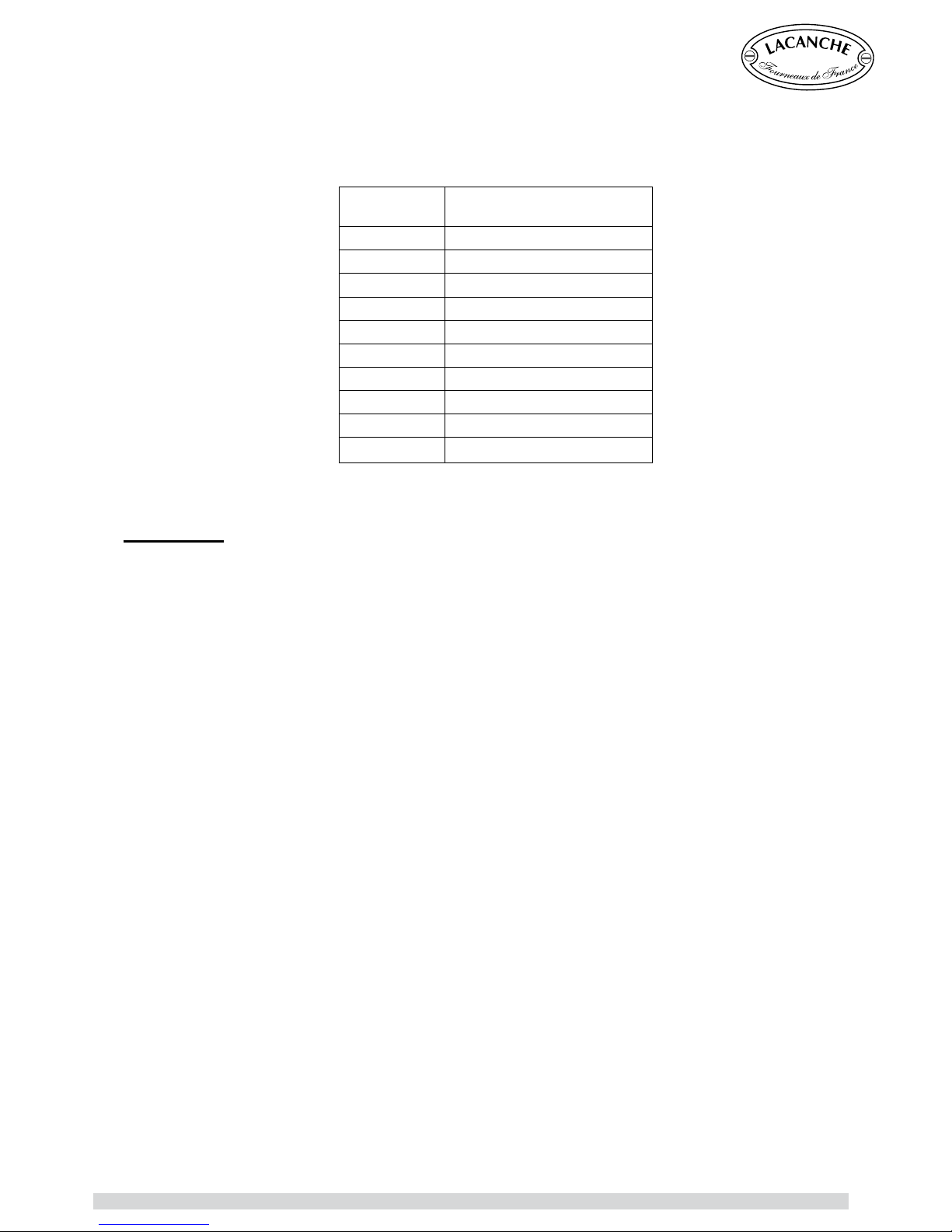
The gas oven marks on you range do not correspond to English gas marks.
The following table indicates the approximate temperature of the gas settings on your cooker.
Chagny - Macon (UK) - Ft 138a - GB - Rév 06 - Modifié le : 07/10/2013 35/42
Page 36
USER’S MANUAL
SMALL ELECTRIC OVEN
The small electric grill oven is simple to use and is designed as general purpose oven for most uses.
It is heated by a base element, and has a ceiling-mounted grill.
It is particulary well suited to cooking pizzas, quiches and flans, the base heat being ideal for cooking
pastry bases. In grill mode it is ideal for finishing off desserts (crème brûlée) or gratins (cheese
topped dishes), and for grilling bacon, sausages etc... . You can use it for toasting, and it also great
for slow cooking dishes such as pork belly.
The small oven takes the same size oven ware as the larger oven in the cooker, meaning food can
be moved easily between the two ovens.
The smaler size makes it ideal for cooking smaller dishes or cooking for fewer people.
It is highly versatil oven.
Description :
Made of sheet steel with an acid-resistant enamel coating applied at 850 °C.
The dimensions of the oven are 400 mm x 145 mm x 440 mm,
25 litre.
The electric oven is supplied equipped with a roasting tray
and a roasting tray insert as standard.
The heating elements consist of a 1500 W element at the
base and a 2400 W element at the grill.
The heating elements are controlled by a thermostatic
switch.
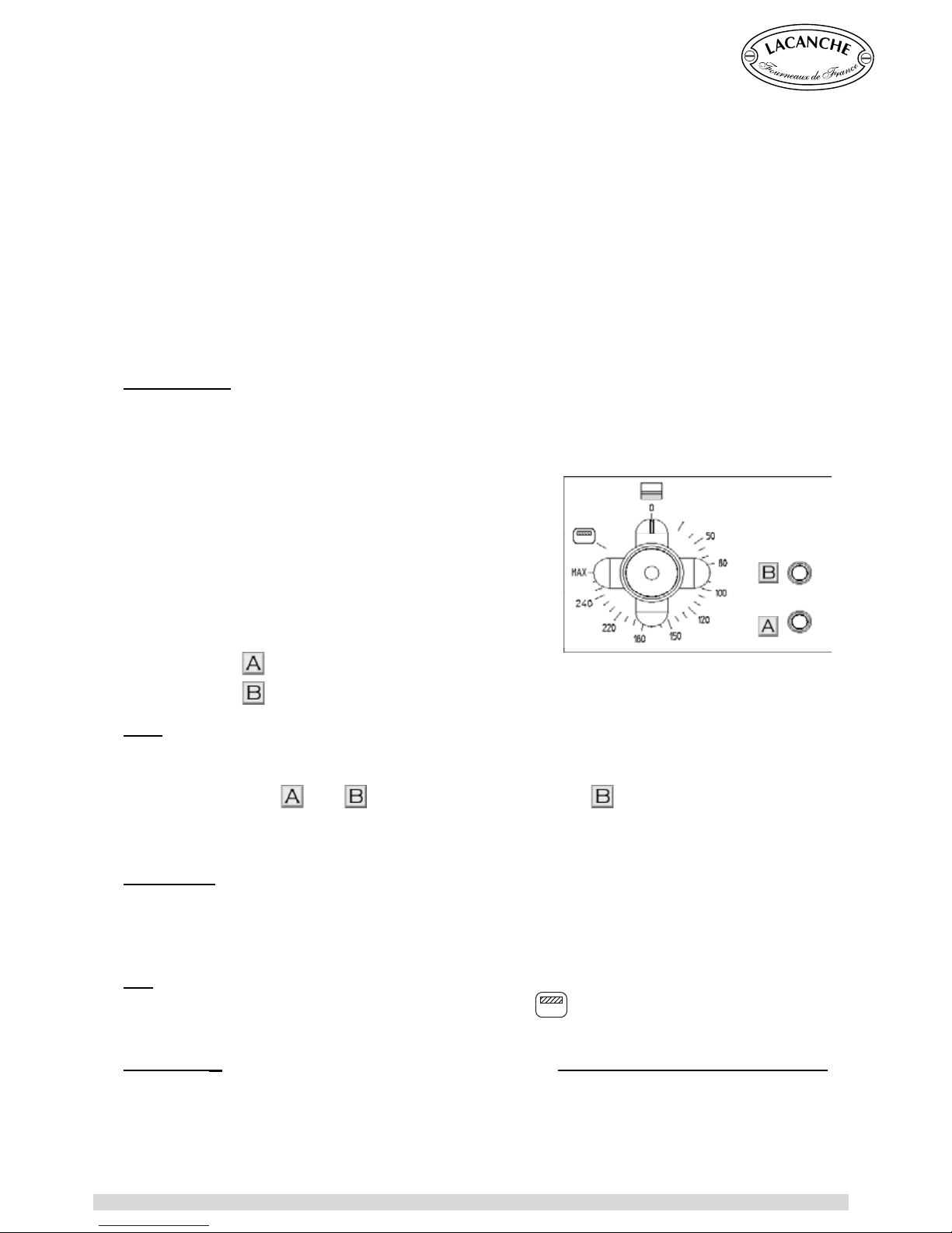
There are 2 indicator lamps on the control panel of the electricoven version :
- Signal lamp
lights when the oven/ grill on.
- Signal lamp
shows status of the oven/ grill in use (see below).
Use :
The oven must be pre-heated at the thermostat setting chosen for cooking.
Turn the thermostat switch clockwise to the required mark.
The indicator lamps (
and ) are lit. When indicator lamp is no longer lit, the selected
temperature has been reached and you can then place your dish in the oven.
To turn off, turn the control knob anti-clockwise to the O position.
Electric grill
The electric oven is equipped with a grill that can be used to grill meat and fish cook all types of
dishes au gratin. The grill is ideal for finishing off crèmes brûlées or to obtain perfect cooking of a
rib of beef.
Use
Turn the thermostat control knob one click further to the
symbol. To turn off, turn the control
knob anti-clockwise to the O position.
Useful hint
: Prior to use, we advise you to read the «Use of the grill on electric ovens”
paragraph in the “Preliminary recommendations for the use of the ovens” chapter of this
manual.
REMEMBER : - GRILL FOOD WITH THE OVEN DOOR CLOSED
- CHECK THE FOOD every minute or so Lacanche grills are extremely powerful.
Chagny - Macon (UK) - Ft 138a - GB - Rév 06 - Modifié le : 07/10/2013 36/42
Page 37
USER’S MANUAL
STATIC ELECTRIC OVEN
Static Electric Ovens are simple to use and are ideal general purpose ovens.
The static electric oven has three heating elements and can be used as both an oven and a grill.
The static electric oven is specially recommended for dry pastries such as almond biscuits,
Genoese sponges, etc.
Description :
Made of sheet steel with an acid-resistant enamel coating applied at 850 °C. The oven have 3 shelf
positions (70 mm spacing) allowing shelves and flatware to slide in easily.
The dimensions of the oven are L x H x P : 400 mm x 305 mm x 405 mm, 55 litre.
The electric oven is supplied equipped with one roasting tray, one grill insert with ts into the
roasting tray and one oven rack insert as standard.
The heating elements consist of one 1500 W element at the base and a peripheral 700 W element
in the roof which operate simultaneously.
In the grill position, only the central element of the 2100 W element in the roof operates.
The heating elements are controlled by a thermostatic switch.
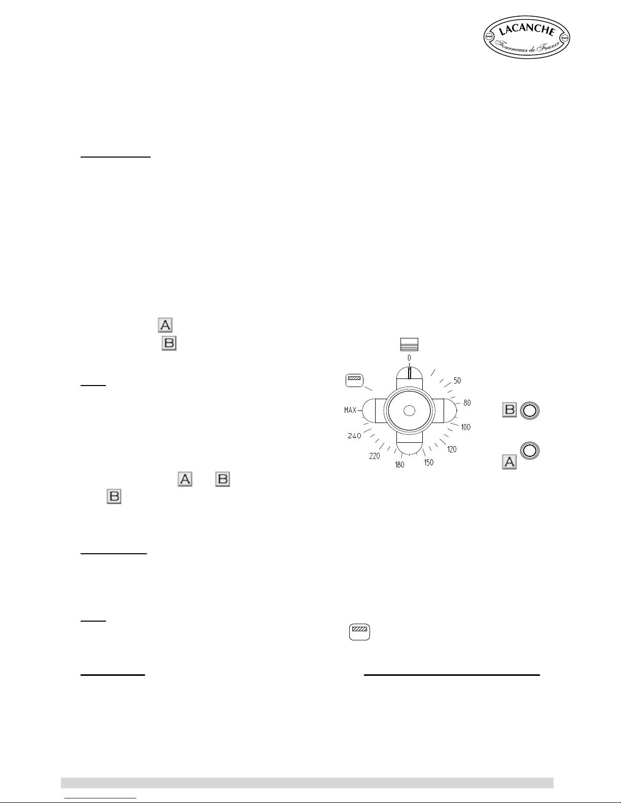
There are 2 indicator lamps on the control panel of the electric-oven version :
- Signal lamp
lights when the oven/ grill on.
- Signal lamp
shows status of the oven/ grill in
use (see below).
Use :
The oven must be pre-heated at the thermostat setting
chosen for cooking.
Turn the thermostat switch clockwise to the required
mark.
The indicator lamps (
and ) are lit. When indicator
lamp
is no longer lit, the selected temperature has been reached and you can then place your
dish in the oven.
To turn off, turn the control knob anti-clockwise to the O position.
Electric grill :
The electric oven is equipped with a grill that can be used to grill meat and fish cook all types of
dishes au gratin. The grill is ideal for finishing off crèmes brûlées or to obtain perfect cooking of a
rib of beef.
Use :
Turn the thermostat control knob one click further to the
symbol. To turn off, turn the control
knob anti-clockwise to the O position.
Useful hint
: Prior to use, we advise you to read the «Use of the grill on electric ovens”
paragraph in the “Preliminary recommendations for the use of the ovens” chapter of this
manual.
REMEMBER : - GRILL FOOD WITH THE OVEN DOOR CLOSED
- CHECK THE FOOD every minute or so Lacanche grills are extremely powerful.
Chagny - Macon (UK) - Ft 138a - GB - Rév 06 - Modifié le : 07/10/2013 37/42
Page 38
USER’S MANUAL
Forced convection ovens have many advantages, the main benefit being that identical or different
dishes can be cooked evenly at several levels. It is therefore particularly suitable for cooking cakes,
pastries, Viennese bread or flaky pastry.
Air circulation is achieved by using one or two turbines inside the oven which draw in air and expel it
onto one or two heating elements, thus producing movement of warm air referred to as “convection”.
Forced convection ovens have many advantages, the main benefit being that identical or different
dishes can be cooked evenly at several levels. It is therefore particularly suitable for cooking cakes,
pastries, Viennese bread or flaky pastry.
It heats quickly and defrosts frozen food evenly.
Different dishes can be cooked simultaneously without taste transference because odours are destroyed
as the air passes over the heating element.
Note : In forced convection oven cooking can take place at temperatures lower 10 to 15°C when using
a convection oven. Also it may be helpful to rotate food (Particulary larger dishes) during the cooking
process.
Description :
Made of sheet steel with an acid-resistant enamel coating applied at 850 °C.
The oven have 3 shelf positions (70 mm spacing) allowing shelves and flatware to slide in easily.
The dimensions of the oven are 400 mm x 305 mm x 405 mm, 49 litre.
The electric convection oven is supplied equipped with an oven rack, a roasting tray and a roasting
tray insert.
The oven is heated by a circular 2650 W element surrounding a fan motor in the back wall of the oven.
There is also an electric grill with a power of 2100 W in the roof
The heating elements are controlled by a thermostatic switch.
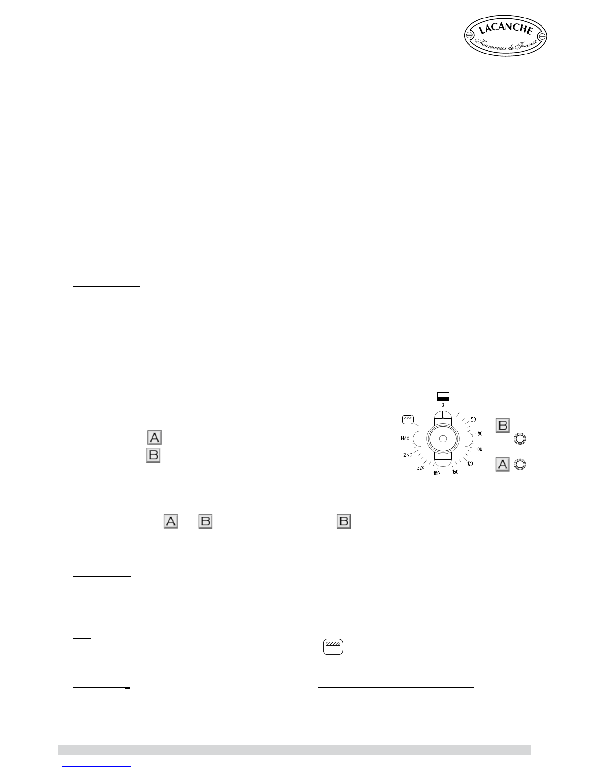
There are 2 indicator lamps on the control panel of the electric-oven
version :
- Signal lamp
lights when the oven/ grill on.
- Signal lamp
shows status of the oven/ grill in use (see below).
Use :
The oven must be pre-heated at the thermostat setting chosen for cooking.
Turn the thermostat switch clockwise to the required mark.
The indicator lamps (
and ) are lit. When indicator lamp is no longer lit, the selected temperature
has been reached and you can then place your dish in the oven.
To turn off, turn the control knob anti-clockwise to the O position.
Electric grill
The electric oven is equipped with a grill that can be used to grill meat and fish cook all types of
dishes au gratin. The grill is ideal for finishing off crèmes brûlées or to obtain perfect cooking of a rib
of beef.
Use
Turn the thermostat control knob one click further to the
symbol. To turn off, turn the control knob
anti-clockwise to the O position.
Useful hint
: Prior to use, we advise you to read the «Use of the grill on electric ovens” paragraph
in the “Preliminary recommendations for the use of the ovens” chapter of this manual.
REMEMBER : - GRILL FOOD WITH THE OVEN DOOR CLOSED
- CHECK THE FOOD
CONVECTION ELECTRIC OVEN
Chagny - Macon (UK) - Ft 138a - GB - Rév 06 - Modifié le : 07/10/2013 38/42
Page 39
USER’S MANUAL
Do not use a steam cleaner to clean the range.
Gas hobs :
The burners are made in two parts in order to facilitate cleaning. Clean them separately,.
→ Burner cap :
Burner caps are made of solid brass. Use a special brass-cleaning product (e.g. MIROR
®
or
BRASSO®) and a soft cloth.
If the product runs onto the enamel do not rub (these products generally contain
abrasives). Rinse immediately with clean water without rubbing.
If the caps are very dirty polish them with very fine sand paper and then rub them with a copper
cleaner.
→ Burner body :
The aluminium bodies of the burners become stained with use. They should be cleaned regularly
with a scouring pad (Scotch Brite
®
).
After removing the pan supports and burners, the cooking surface can be cleaned easily and
thoroughly by simply using a sponge.
Do not use scouring pads or abrasive products such as oven cleaners and stain removers.
When cleaning, be careful not to splash liquid into the openings of the burners.
Traditional Hob (Simmer Plate) :
Do not use water to clean the simmer plate when it is hot. This can damage it.
Immediately remove any spillages to make cleaning easier.
Use a sponge moistened with soapy water or scouring powder.
Radiant Electric hob :
Hotplates must ALWAYS be kept dry. Wipe your pans before placing them on the hotplates.
Limescale can be removed by using white wine vinegar. Cover the marks with a cloth soaked in wine
vinegar and leave for 1/2 h before carefully rinsing and drying.
Marks made by metal or superficial deposits which remain after the standard cleaning described
above can be removed by using a liquid product for cleaning stainless steel pans (e.g. cream
stainless steel ZIP ®, stainless steel PPZ ®, etc.).
The stainless steel frame can be cleaned by using a damp sponge with a mild detergent for stubborn
marks (e.g. CIF Ammoniacal ®, etc.).
If any sugar-based syrup falls on the glass ceramic hob during use, leave the element switched
to position 1, and, using a razor blade scraper (such as CERA Quick) IMMEDIATELY remove the
remaining burnt-on layer.
CAUTION
If there is any visible sign of a surface crack, immediately isolate appliance from the
electrical supply to prevent risk of electric shock. Contact your installer.
Before any cleaning work, close the gas supply and/or isolate from
the mains electricities supply
CLEANING AND MAINTENANCE
Chagny - Macon (UK) - Ft 138a - GB - Rév 06 - Modifié le : 07/10/2013 39/42
Page 40
USER’S MANUAL
Stainless steel bodied Cookers :
Use special stainless steel cleaners (ZIP INOX®, JOHNSON INOX®, PPZ INOX®, for instance). Do
not use abrasive cleaners.
Stainless-steel hop :
The entire hob is pressed or comprises pressed recesses for easy cleaning and improved hygiene
(no water trap). The hob should be cleaned with liquid, non-chlorinated products to avoid scratching
the steel.
If the hob is stained use a clay stone- and soap-based paste available from department stores.
Brushed Stainless-steel trim :
The brushed stainless-steel trim should be cleaned with aerosol products available from department
stores. You should nevertheless choose a cleaner that contains only a small quantity of silicone to
avoid leaving white streaks after the product dries.
Brass trim :
Use a special brass-cleaning product (e.g. MIROR® or BRASSO®) and a soft cloth. If the product runs
onto the enamel do not rub (these products generally contain abrasives). Rinse immediately with
clean water without rubbing.
Another solution is to use solid soap (Pierre d’argent, Pierre d’argile) applied with a damp sponge to
the zones to be cleaned.
This solution is also very effective for cleaning and bringing a shine back to brass or chrome surfaces.
Enamelled surfaces :
Use a sponge soaked in soapy water or a window-cleaning product but never scouring powder.
You can also use methylated spirit but only when the range is cold.
Ovens :
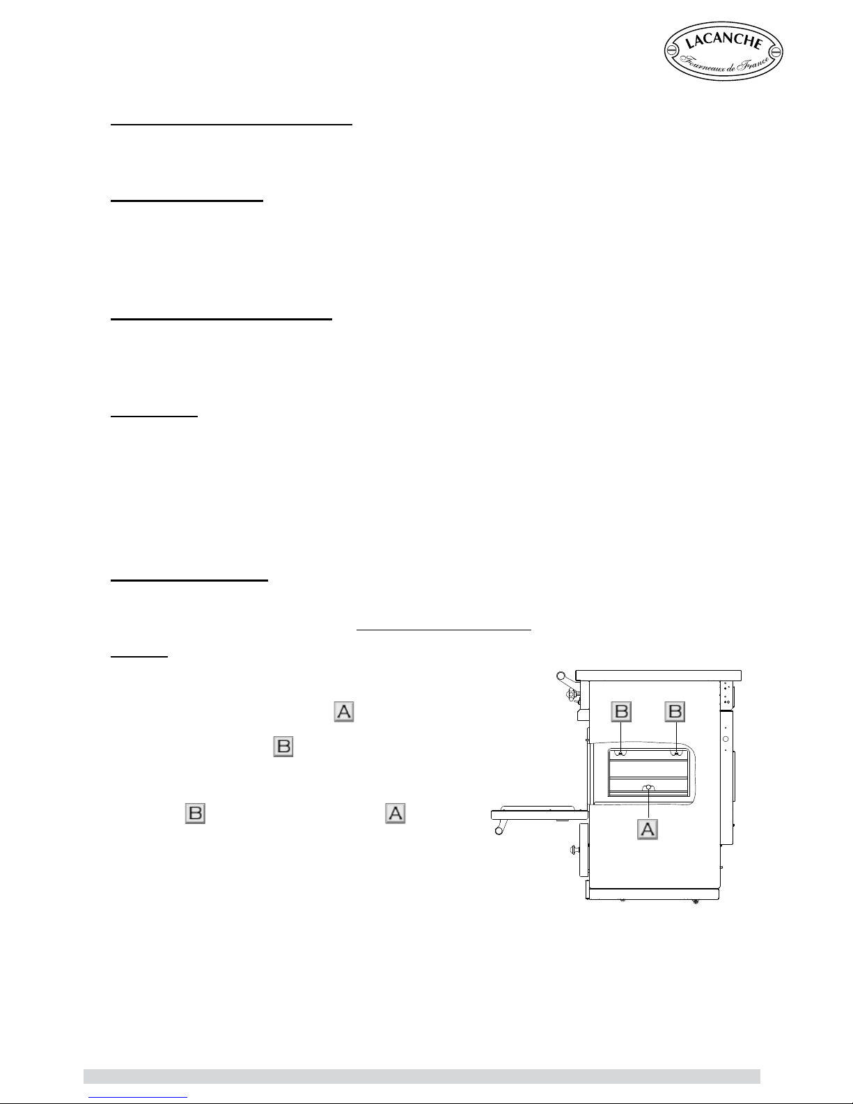
Be sure the power supply is disconnected and the ovens
are cold.
Remove scales: Loosen the screw
with your hand.
Slide the brackets a small distance upwards to disengage
the bracket from the lugs .
Caution : To remove the brackets, be sure the brackets
are locked
on the lugs
before loosening the screw .
Clean the side panels with a non abrasive cleaning
agent. Harsh cleaning agents should not be used. If you
use such product, first remove the oven door seals and
reinstall after cleaning.
Rinse and dry.
After cleaning, replace the back panel with the screws and the washers. Be sure you the screws
are correctly screwed.
CLEANING AND MAINTENANCE
Chagny - Macon (UK) - Ft 138a - GB - Rév 06 - Modifié le : 07/10/2013 40/42
Page 41
USER’S MANUAL
CAUTION
Use NON chlorinated cleaners to clean this unit.
Carefully read the precautions and recommendations for applying the products you
use to clean and maintain the range. Follow the instructions for use.
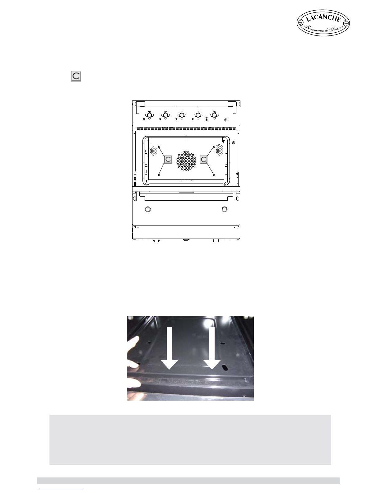
If you have a convection oven, clean the back wall protecting the turbine at least once a year. The
grease carried by airflow and when the range is used at lower temperatures can create smoke. Do
not allow cleaner into the fans. It is advisable to remove the back panel for cleaning: unscrew the 4
screws
.
After cleaning, replace the back panel with the screws and the washers. Be sure you the screws
are correctly screwed.
Do not spray strong cleaning products directly onto the elements in the electric ovens.
After cleaning, before use make sure that the base plate is properly tted under the groove in the
fascia in order to avoid deformation of the base due to heat.
CLEANING AND MAINTENANCE
Chagny - Macon (UK) - Ft 138a - GB - Rév 06 - Modifié le : 07/10/2013 41/42
Page 42
USER’S MANUAL
Government Order No. 2005-829 dated 20 July 2005 relative to the composition of
electrical and electronic equipment and the elimination of waste resulting from such
equipment implementing European Directives 2002/95/EC and 2002/96/EC.
Electrical and electronic equipment (EEE) and Waste from Electric and Electronic
Equipment (WEEE) are regulated in Europe by two directives whose aim is to limit the
use of hazardous substances in EEEs and to encourage the re-use, recycling and other
forms of recovery of WEEEs in order to reduce the quantity of waste to be eliminated.
Users of electrical and electronic equipment must not throw WEEEs away along with
unsorted municipal waste.
Users are provided with suitable waste collection systems.
By complying with these Orders users of electrical and electronic equipment avoid
effects that are potentially harmful to the environment and public health. They also help
preserve natural resources.
Information regarding the elimination of
electric and electronic waste
Each item of electrical and electronic equipment marketed after 13
August 2005 must display this sign.
The sign means that the equipment should not be thrown away with
other waste, that it is collected separately in order to be recovered,
reused or recycled.
Chagny - Macon (UK) - Ft 138a - GB - Rév 06 - Modifié le : 07/10/2013 42/42
 Loading...