


Fourneau
«
MÂCON »
MANUEL GENERAL
GENERAL MANUAL
Page 1 sur 43– FT138a – FR / GB – Date de mise à jour : 02/02/04- Indice : 03

MANUEL GENERAL
GENERAL MANUAL
210
489
380
100
497
500
1000
497
304
MÂCON
380
319
815
Fig.1
650
29
914
256
241
Option four basse température
Option for low-temperature
500
Nota : T*Cet appareil est réglable de : 860 mm à 870 mm
T* The range Height is adjustable : 860 mm to 870 mm
Page 3 sur 43– FT138a – FR / GB – Date de mise à jour : 02/02/04- Indice : 03
304
Fig.2
MANUEL GENERAL
GENERAL MANUAL
MÂCON
FR
Présentation
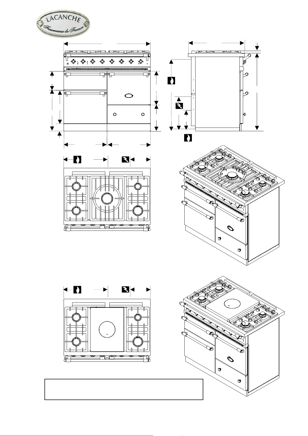
Fourneau 5 feux sur 3 fours (fig.1, 2).
Description
Table et carrosserie
Carrosserie acier émaillé ou inoxydable Z7CN 18.10.
Table emboutie inox Z7CN 18.09 (voir Brûleurs T, A,
B, C, D tableau 1, annexe 0, fig. 1). 5 brûleurs de taille
et de puissance différente commandés individuellement
par un robinet à sécurité (thermocouple).
Modèle « TRADITION » équipé d’une plaque coup de
feu 385x510 mm (figure 2).
Allumage électrique des brûleurs de table par bouton
poussoir.
FR
Four électrique gril
Tôle émaillée ou acier inoxydable Z8C17.
Dimension L x P x H : 400 x 440 x 145
1 niveau de platerie, 25 litres.
Résistances de voûte et de sole thermostatées,
thermostat de sécurité. Four :1800 W, grilloir électrique
de 2400 W
Puissance : 1800/2400 W
Alimentation 230 V 1N~ 50 Hz
GB
Layout
5-burner cook’s stove, 3 ovens (Figure 1, 2).
Description
Cooking surface and body panels
Enamelled steel or stainless body panels Z7CN 18.10.
Pressing cooking surface stainless steel Z7CN 18.09
(see Burner T, A, B, C, D table 1 in appendix 0, Figure
1). 5 burner of different size and power individually
controlled by a safety valve (thermocouple).
“TRADITION” model (Figure 2) equipped with a 385 x
510 mm heating plate.
Pushbutton cooktop burner ignition.
FR
Four électrique gril
Enamelled sheet metal or stainless stell Z8C17.
Dimension L x P x H : 400 x 440 x 145
1 shelf level, 25 liters.
Thermostatically controlled roof and base heating
elements, safety cut-out by safety thermostat. Oven :
1800 W, electric grill with a rating of 2400 W.
Rating : 1800/2400 W
Power supply : 230 V 1N~ 50 Hz
FR
Four gaz
Tôle émaillée ou acier inoxydable Z8C17. Dimensions
L x P x H : 400 mm x 460 mm x 305 mm. 4 niveaux de
platerie au pas de 58 mm, 55 litres. Chauffe assurée par
brûleur contrôlé par thermostat, sécurités par
thermocouple. Allumage de four par bouton poussoir.
FR
Four gaz basse température (option)
(FBT) :
Idem four gaz, mais régulation assurée par une vanne
thermostatique associée à un bloc veilleuse à ré
allumage automatique. Allumage électrique par bouton
poussoir.
FR
Four électrique ventilé
Chauffe assurée par une résistance circulaire entourant
une turbine à réaction. Dimensions L x P x H : 400 mm
x 405 mm x 305 mm. Celui-ci peut-être équipé, en
option, d’un grilloir électrique d’une puissance de 2400
W.
Résistance thermostatée, thermostat de sécurité.
Puissance : 2650 W – Alimentation 230 V 1N~ 50 Hz
Four électrique statique (option)
Même dimensions que le four gaz.
Résistances de voûte et de sole thermostatées,
thermostat de sécurité. Grilloir électrique de 2400 W
Puissance : 2500 W – Alimentation 230 V 1N~ 50 Hz
GB
Gas oven
Enamelled sheet metal or stainless stell Z8C17.
Dimensions L x W x H : 400 mm x 460 mm x 305 mm.
4 shelf level with 58 mm spacing, 55 liters. Heating
provided by thermostatically controlled burner,
thermocouple safety cut-outs. Pushbutton oven ignition.
GB
Low-temperature oven (option) (LTO) :
Ditto, gas oven but adjustment obtained by a
thermostatic valve associated with a pilot light with
automatic re-ignition. Electric ignition via push button.
GB
Ventilated electric oven
Heating provided by circular heating element
surrounding a reaction fan. Dimensions L x W x H :
400 mm x 405 mm x 305 mm. This can optionally be
fitted with an electric grill with a rating of 2400 W.
Thermostatically controlled heating elements, safety
cut-out by safety thermostat.
Rating : 2650 W – Power supply : 230 V 1N~ 50 Hz
Static electric oven (option)
Same dimensions as gas oven.
Thermostatically controlled roof and base heating
elements, safety cut-out by safety thermostat. Electric
grill with a rating of 2400 W.
Rating : 2500 W – Power supply : 230 V 1N~ 50 Hz
Page 4 sur 43– FT138a – FR / GB – Date de mise à jour : 02/02/04- Indice : 03
MANUEL GENERAL
N
N
~
f
GENERAL MANUAL
MÂCON
Appareil
Appliance
LG 1053 EG
FR
Raccordement gaz
Tube ∅ 15/21, filetage 1/2 ” gaz, sur raccord femelle
(figures 1et 2).
Largeur Profondeur Hauteur Poids brut / Net
Width Depth Height mm Weight Gross/Net
1130 mm 760 mm 1050 mm 120 kg /108 kg
Changement de gaz
Appareil adaptable (tableau 2 et 3), se reporter à la
plaque signalétique et marquage au dos de l’appareil.
Conseils
Gaz butane : Raccorder l’appareil à la sortie d’un
détendeur de 2,6 kg/h. 2 bouteilles jumelées à l’entrée
du détendeur sont indispensables pour obtenir un
fonctionnement correct de l’appareil en cas d’utilisation
globale et prolongée.
Gaz propane : Raccorder l’appareil à la sortie d’un
détendeur de 3,0 kg/h. 2 bouteilles jumelées à l’entrée
du détendeur sont indispensables pour obtenir un
fonctionnement correct de l’appareil en cas d’utilisation
globale et prolongée. L’alimentation par bouteille de 37
kg ou citerne cryogénique est possible et recommandée.
GB
Gas connection
Tube ∅ 15/21, 1/2” gas thread, on female coupling
(Figures 1and 2).
Gas supplying
Appliance gas supplying can be switched (Table 2 and
3), please refer to rating plate and marking at the rear o
the appliance.
Advice
Butane-fuelled units: Connect unit to 2.6 kg/h pressure
reducer. Use two cylinders connected to a 3-way valve
ahead of the pressure regulator in case of prolonged,
continuous duty.
Propane-fuelled units: Connect unit to a 3.0 kg/h
pressure reducer. Use two cylinders and a 3-way valve
ahead of the pressure regulator in case of prolonged,
continuous duty. The use of 37 kg or extern cryogenic
tanks is both possible and recommended.
FR
Pressions et consommations horaire
F/O, T, A, B, C, D : tab.4, annexe 0
FR
Raccordement électrique
Sur bornier au dos de l’appareil (fig.1, 2) .
ota: Dans le cas de 2 fours électriques l’alimentation
se fait uniquement par la droite (figure 4). Voir tension
inscrite sur la plaque signalétique.
Appareils commutables 230 V 1N~50 Hz / 400V 3N~
50 Hz.
FR
Directives
Appareils à gaz : 90/396/CEE
Basse tension : 73/23/CEE
CEM : 89/336/CEE
GB
Pressures and hourly consumption
F/O, T, A, B, C, D : tab.4 in appendix 0
GB
Electrical connection
On terminal block at the rear of the appliance (Figures
1, 2).
ote : In the case of 2 electric ovens, power supply is
routed either via the left or via the right (Figure 4). Note
the voltage and rating shown on the rating plate.
Appliances are switchable 230 V ~50 Hz / 400V 3N
50 Hz.
GB
Directives
Gas appliances : 90/396/CEE
Low Voltage
CEM : 89/336/CEE
: 73/23/CEE
Page 5 sur 43– FT138a – FR / GB – Date de mise à jour : 02/02/04- Indice : 03


Fourneau
«
MÂCON »
MANUEL D’INSTALLATION
INSTALLER'S MANUAL
FR
notice et les règlements en vigueur dans le pays d’installation.
GB
and locally applicable regulations.
L’installation doit se faire selon les règles de l’art conformément aux instructions contenues dans cette
Ce manuel sera remis à l’utilisateur après installation.
Appliances must be installed in a workmanlike manner in accordance with the instructions in this manual
This manual will be handed over to the user after installation.
Page 7 sur 43– FT138a – FR / GB – Date de mise à jour : 02/02/04- Indice : 03

MANUEL D’INSTALLATION
INSTALLER’S MANUAL
MÂCON
FR
Implantation
Positionnez l’appareil de niveau à l’aide de ses vérins.
Respecter un écart minimum de 50 mm entre l’appareil
et les autres surfaces (parois sensibles à la chaleur).
Dans le cas où l’appareil devrait être intégré entre deux
surfaces, il est IMPERATIF de prévoir la libre
circulation de l’air à l’arrière (prévoir un dosseret). De
même la table de cet appareil ne devra JAMAIS se
situer en dessous des plans de travail adjacents. Il est
également conseillé de laisser déborder la face avant de
l’appareil de 50 mm par rapport aux meubles de côté.
Installer impérativement sous une hotte d’extraction.
Si cet appareil doit être mis en place près d’un mur,
d’une cloison, d’un meuble, de bordures décoratives. Il
est recommandé que ceux -ci soient faits d’un matériau
non combustible. Si ce n’est pas le cas, ils doivent être
recouverts d’un matériau approprié, bon isolant
thermique non combustible. Une attention toute spéciale
étant accordée aux réglementations de prévention des
incendies.
Une vanne d’arrêt doit être installé sur le réseau
d’alimentation gaz de l’appareil, permettant d’isoler
aisément l’appareil (suivant EN ).
GB
Cabinet preparation
Adjust this appliance by using the levelling feet.
Allow a minimum clearance of 50 mm between the
appliance and any other surfaces (walls affected by
heat).
If the appliance is to be built in between two surfaces, it
is CRUCIAL to allow free circulation of air behind the
appliance (provide shielding at rear). The cooker hob
must NEVER be at a lower level than the surrounding
worktops. It is also recommended to install the range so
that the front part stands out by 50 mm in relation with
the adjacent kitchen units.
Must be installed under an extractor hood.
Do not install this unit near combustible walls,
partitions, pieces of furniture or decorative material
unless these are covered with adequate thermal
insulation of the noncombustible type. Making sure the
resulting installation meets local fire regulations.
Manual shut-off valve should be installed in an
accessible location in the gas piping external to the
appliance for the purpose of turning on or shutting
off gas to the appliance (according to EN).
FR
Avant raccordement
Contrôlez :
- Le parfait état de propreté des canalisations, afin
d’éviter l’obstruction des injecteurs et le
dysfonctionnement des têtes magnétiques.
- Le gaz pour lequel l’appareil à été réglé : plaquette
signalétique et marquage.
- La compatibilité de la section des canalisations
d’alimentation avec la puissance de l’appareil.
- La conformité du débit d’air neuf.
FR
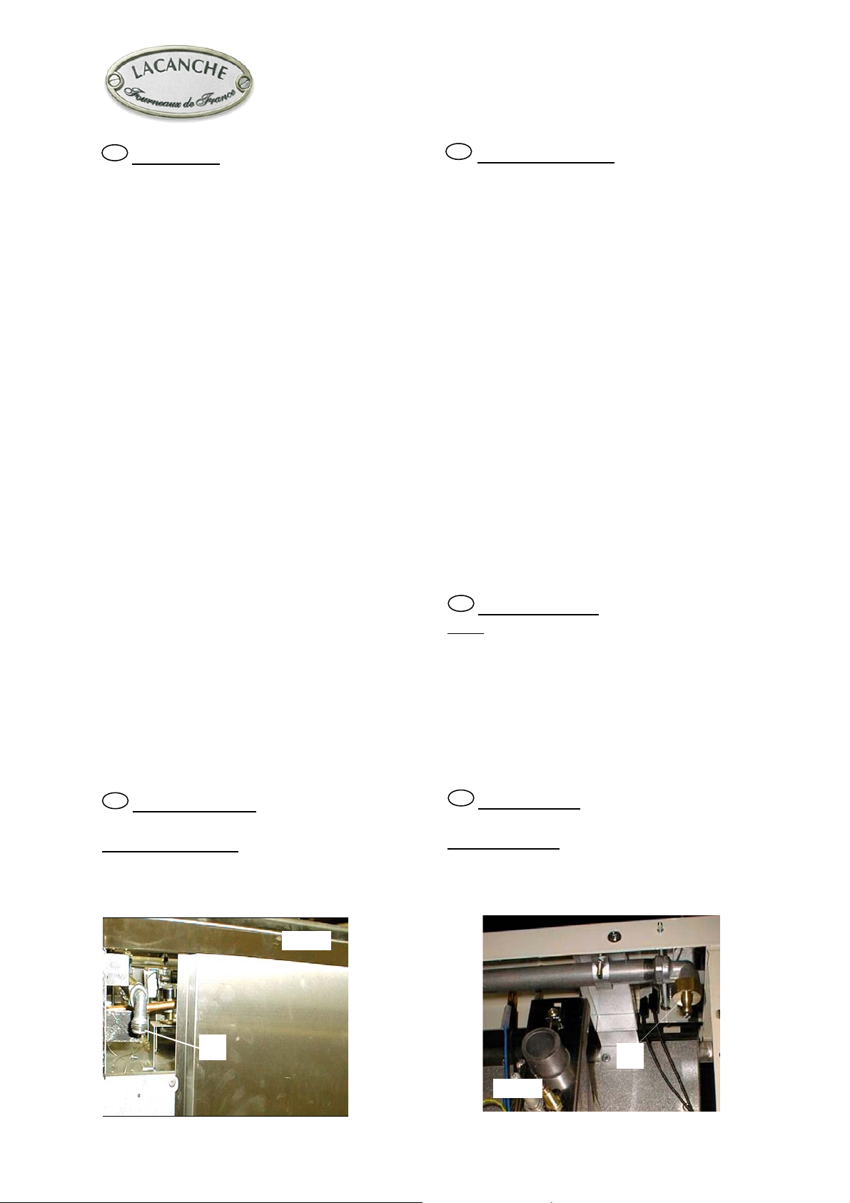
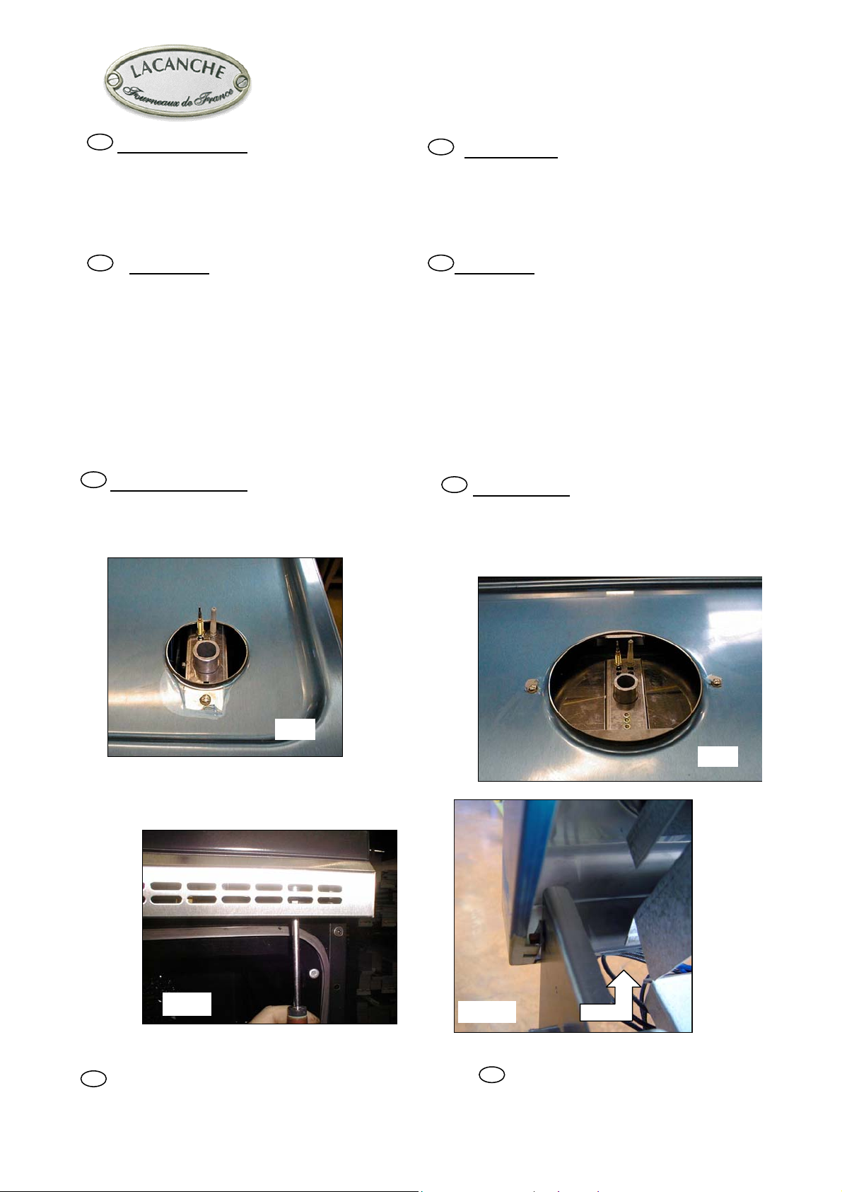
Raccordement gaz
Raccord femelle Ø 15/21, filetage 1/2” gaz (A fig. 3).
Après raccordement
Contrôler la pression d’alimentation sur prise de
pression B (fig. 4).
Fig. 3
GB
Before connection
Check :
- Pipework is perfectly clean in order to prevent the
injectors becoming blocked and malfunctioning of the
magnetic heads.
- The gas for which the appliance was set up : Rating
plate and markings.
- Cross-sectional area of gas supply pipework is
compatible with the appliance’s thermal output.
- Provide adequate air supply during use of the appliance.
GB
Gas connection
Female coupling Ø 15/21, 1/2” gas thread (A Figure. 3).
After connection
Check the manifold pressure on pressure connection on
B (Figure 4).
A
Fig. 4
Page 9 sur 43– FT138a – FR / GB – Date de mise à jour : 02/02/04- Indice : 03
B
MANUEL D’INSTALLATION
u
INSTALLER’S MANUAL
FR
Changement de gaz
L’appareil est prévu pour fonctionner avec les gaz du
tableau 5 en annexe 0.
IMPORTANT : Fermez la vanne d’arrêt gaz
avant d’effectuer toutes interventions.
MÂCON
GB
Change of gas
The appliance is designed to operate with the gases in
Table 5 in appendix 0.
IMPORTANT : Close the mains gas valve
before carrying out any works.
FR
Spécial U.K :
L’appareil prévu pour être relier à un circuit en gaz
naturel est équipé d’un régulateur de pression gaz
permettant à cet appareil de fonctionner sous une
pression de 15 mbar.
Dans le cas d’un changement de gaz, il est nécessaire de
retirer ce régulateur de pression et d’alimenter l’appareil
en gaz butane ou propane directement au point de
raccordement de l’alimentation gaz de l’appareil.
Procéder, comme lors de tout changement de gaz, aux
nouveaux réglages (injecteurs, air primaire, …). Voir
annexe technique 0.
FR
Ouverture du dessus
Dévisser les vis situées près des ouvertures des brûleurs
(fig. 5 et 6). Enlever grilles et brûleurs, tirer et lever le
dessus après avoir desserrer les 2 vis (fig. 7 et 8), caler
la table.
GB
Spécial U.K :
The oven is designed to run on natural gas and is
therefore fitted with a pressure regulating valve that
allows it to be used at a pressure of 15 mbar.
If a different type of gas is to be used, this pressure
regulating valve must be removed and the gas supply
connected directly to a source of butane or propane.
As always when changing the type of gas, the injectors,
primary air, etc. must be adjusted. See technical
appendix 0.
GB
To remove top
Unscrew the screws near the burners openings (Figures
5 and 6). Remove the pan supports and burners, pull
and raise the top after having loosened the 2 screws
(Figures 7 and 8), wedge the cooking surface.
Fig. 5
Fig. 7
IMPORTANT
FR
En cas d’utilisation avec un gaz autre que celui d
réglage initial, il est impératif de procéder à l’échange des
injecteurs et de reprendre les réglages comme définis ciaprès. Vérifier ensuite l'étanchéité du circuit.
Fig. 6
Fig. 8
IMPORTANT
GB
In case of use with a gas other than that for which
the appliance was initially set up, it is crucial to replace
the orifices and modify the adjustments as defined
below. Subsequently check the circuit for gas leaks
Page 10 sur 43– FT138a – FR / GB – Date de mise à jour : 02/02/04- Indice : 03
MANUEL D’INSTALLATION
INSTALLER’S MANUAL
MÂCON
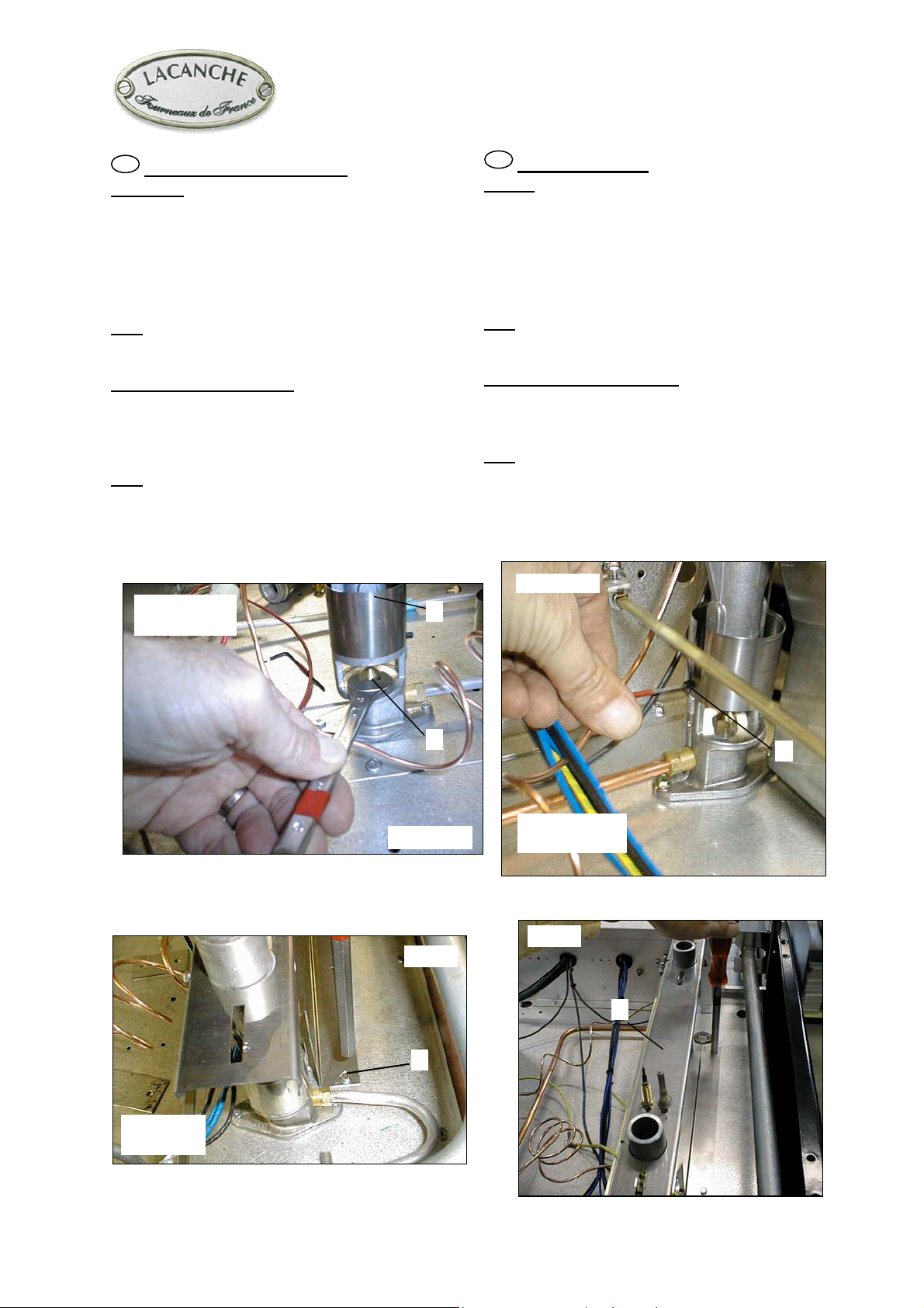
FR
BRÛLEURS DE TABLE
Injecteurs :
Relever les bagues d’air D. Remplacer les injecteurs E
suivant tableau 6 (Brûleurs F/O, T, A, B, C, D) en
annexe 0 et figure 9 ( Ø en 1/100mm).
Les corps des brûleurs latéraux sont maintenus par une
traverse (H, fig. 12). Pour les dégager, dévisser les vis F
(fig. 10) puis la vis (G, fig. 11).
Nota : Lors du remplacement d’un (des) injecteur(s),
remplacer également la rondelle d’étanchéité (voir
schéma de gazage).
Réglage de l’air primaire
Reposer corps et chapeau sur leur brûleur respectif,
régler la bague d’air D en la faisant coulisser de bas en
haut (fig. 9, Brûleurs F/O, T, A, B, C, D : tableau 7 en
annexe 0).
Nota : Des flammes normales ont une couleur bleu-vert.
sauf pour le gaz naturel où elles sont violettes.
Clé de 12
Wrench 12
D
GB
TOP BURNERS
Orifice
Lift the air ring D. Replace the injectors E in accordance
with tab. 6 (Burners F/O, T, A, B, C, D) in appendix 0
and Figure 9 (Ø in 1/100 mm).
The side burner bodies are kept in place by a transversal
bar (H, fig. 12). In order to take them out, unscrew
screws F (fig. 10) then G (fig. 11).
Note : When one or more nozzles are changed, the
sealing ring should be changed as well (see gas circuit
diagram).
Adjustment of primary air
Put body & cap back on their respective burners, set air
ring D by sliding it from bottom to top (fig. 9, T, A, B,
C, D : tab.7 in appendix 0).
Note : Normal flames are bluish green except for
natural gas flames which are violet.
Fig. 10
Clé de 7
Wrench 7
E
Fig. 9
Fig. 11
G
F
Clé de 2
Wrench 2
Fig. 12
H
Page 11 sur 43– FT138a – FR / GB – Date de mise à jour : 02/02/04- Indice : 03
MANUEL D’INSTALLATION
INSTALLER’S MANUAL
I
Fig. 13
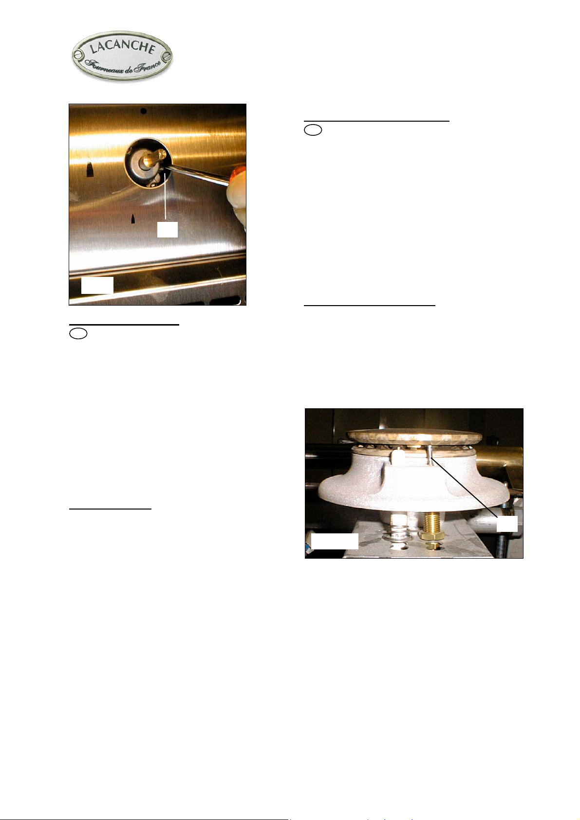
Réglage du débit réduit
FR
Après raccordement ou changement de gaz, il est
impératif de reprendre ce réglage. Déposer la manette,
allumer le brûleur, passer en position min., puis agir à
l’aide d’un tournevis sur la vis de réglage I (fig. 13).
Nota: les flammes sont réduites au ¼ de leur taille en
position mini, le brûleur ne doit pas s’éteindre en
passant de la position maxi à la position mini.
Réglage des sécurités par thermocouple
Si le brûleur s’éteint, après avoir maintenu enfoncée à
fond la manette une vingtaine de secondes; vérifier : Le
serrage (modéré) de la tête magnétique sur le robinet,
que la pointe du thermocouple J soit bien léchée par la
flamme (fig. 14) et le bon état de propreté des
thermocouples et têtes magnétiques.
Repose de la table
Lors de la repose de la table, fixer impérativement les
vis de maintien. De table, ce non respect pouvant
entraîner une déformation de celle-ci.
MÂCON
Adjustment of reduced flowrate
GB
After connection or change of gas, it is crucial to
modify this adjustment. Remove the control knob. Light
the burner, adjust to minimum setting, then use a small
screwdriver to set the adjusting screw I (Figure 13).
Note : Flame is reduced to ¼ of its size in the minimum
setting, the burner must remain lit when changing from
maximum setting to minimum setting.
Adjustment of thermocouple safety cut-outs
If the burner goes out, having kept the control knob
pushed in for roughly twenty seconds, check :
(Moderate) tightening of magnetic head on the valve,
the thermocouple J tip actually touches the flame
(Figure 14). and the thermocouples and magnetic heads
are clean.
Refitting the cooking surface
When refitting the cooking surface, it is vital to tighten
fastening screws. Failure to do so can cause distortion
of the cooking surface.
J
Fig. 14
Page 12 sur 43– FT138a – FR / GB – Date de mise à jour : 02/02/04- Indice : 03
MANUEL D’INSTALLATION
f
N
a
N
INSTALLER’S MANUAL
MÂCON
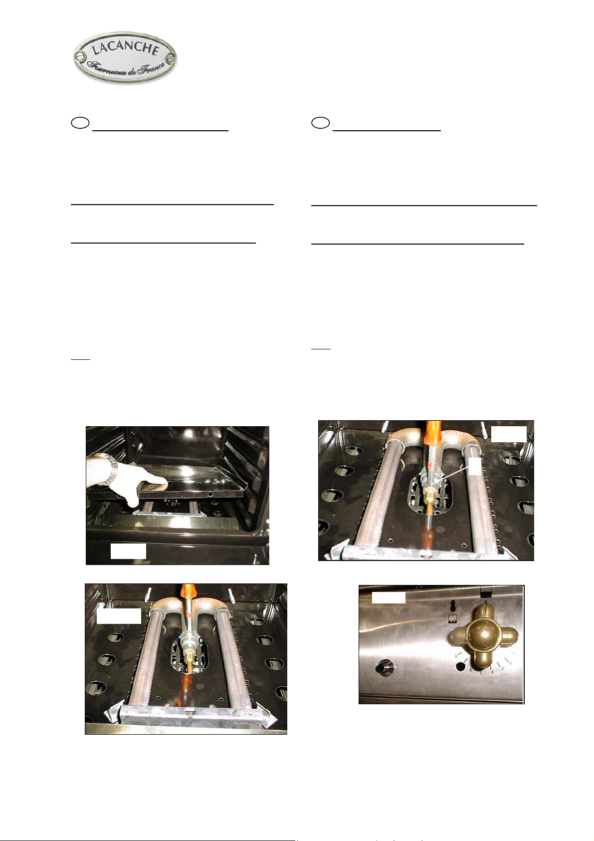
BRÛLEUR DE FOUR
FR
Injecteur de four (tous fours)
Retirer la sole, ATTENTION lors de la repose, bien l
ramener sous le pli de la façade (fig. 15)
Désaccoupler la tubulure, dévisser la vis K du porte
injecteur (fig. 16). Echanger l’injecteur (tableau n° 8 en
annexe 0).
Réglage de l’air primaire four( tous fours )
Dévisser la vis de maintien de la bague d’air, procéder
au réglage (fig. 17, tableau n° 8 en annexe 0).
Réglage du débit réduit de four (fig. 18)
IMPERATIF après raccordement et tout changement de
gaz.. Vis de réglage accessible après dépose de la
manette de commande.
- Allumer le brûleur correspondant, préchauffer le four
environ 1/4 d’heure (thermostat 10), passer en position
mini (thermostat 1), puis agir à l’aide d’un petit
tournevis sur la vis de réglage (agir rapidement avant
que le thermostat ne réagisse et que le brûleur ne
repasse au débit maximum).
ota: les flammes sont réduites au ¼ de leur taille en
position maxi, le brûleur ne doit pas s’éteindre en
passant de la position maxi à la position mini.
OVEN BURNER
GB
Oven orifice (all ovens)
Remove the base, CAUTION: when refitting place the
base underneath the groove on the fascia (Figure 15).
Disconnect the connection piece, unscrew screw K on the
orifice holder (Figure 16). Replace the orifice (Table 8 in
appendix 0).
Adjustment of oven primary airflow (all ovens )
Loosen the screw that secures the air ring and then adjust
(Figure 17, Table 8 in appendix 0).
Adjustment of oven reduced flowrate (fig. 18)
Adjustment is VITAL after connection or any change o
gas. The adjusting screw is accessed by removing the
control knob.
- Light the appropriate burner, pre-heat the oven for
roughly 1/4 hour (thermostat 10), adjust to minimum
setting (thermostat 1), then use a small screwdriver to set
the adjusting screw (do this quickly before the thermostat
responds and the burner returns to the maximum setting).
ote: flame is reduced to ¼ of its size in the maximum
setting, the burner must remain lit when changing from
maximum setting to minimum setting.
Fig. 15
Fig. 17
Fig. 16
K
Fig. 18
Page 13 sur 43– FT138a – FR / GB – Date de mise à jour : 02/02/04- Indice : 03
 Loading...