

Page 1
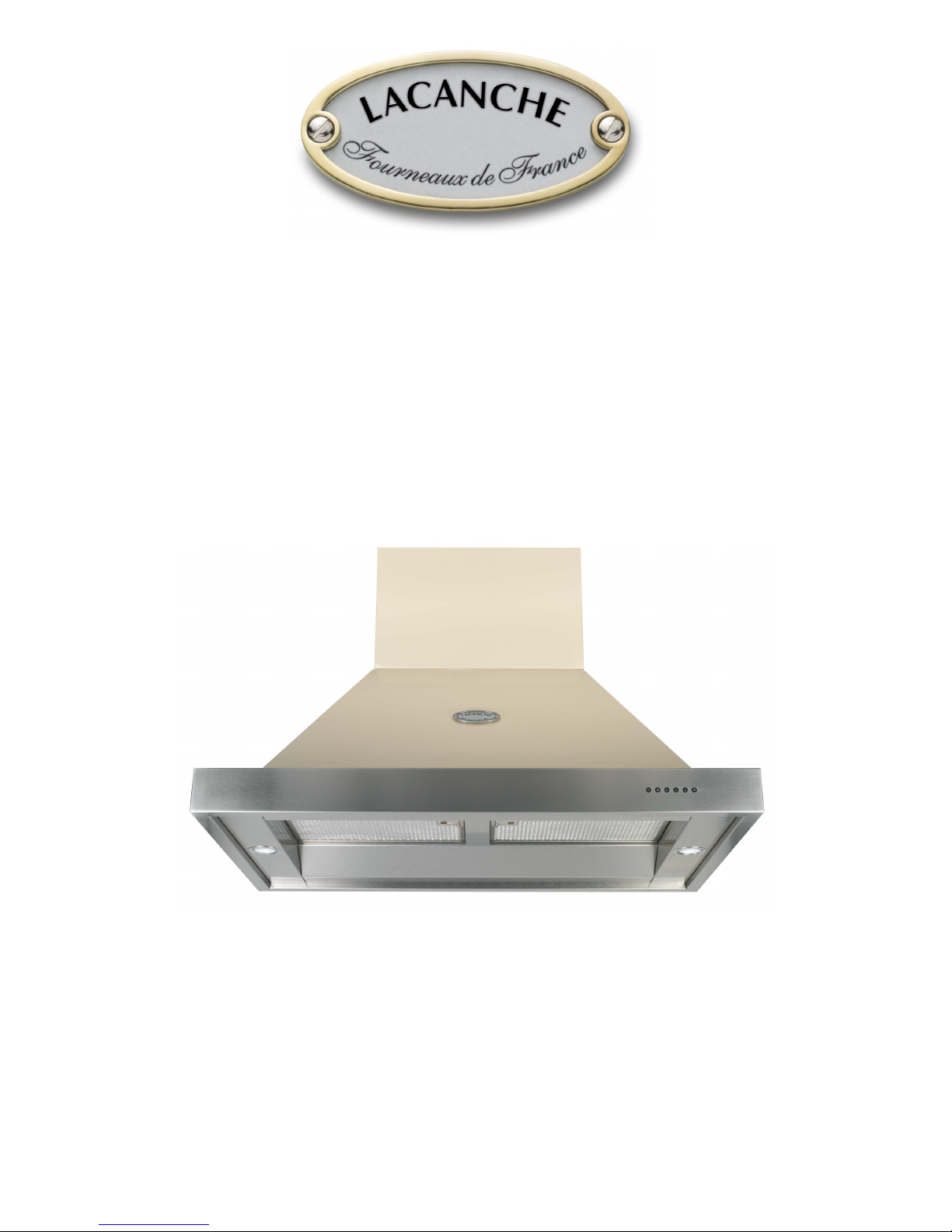
FMH Range Hoods
W1103 Revision: 14/10/2011 1
FMH Range Hoods
Installation, Operation & Maintenance Instructions
Fourneaux de France Ltd
Unit 3 Albion Close, Newtown Business Park, Poole Dorset, BH12 3LL
Tel 01202 - 733011 Email [email protected] www.fdef.co.uk
Page 2

FMH Range Hoods
W1103 Revision: 14/10/2011 2
FMH Range Hoods
SECTION 1. INTRODUCTION
SECTION 2. EXTRACTION PERFORMANCE
SECTION 3. IMPORTANT INFORMATION
SECTION 4. INSTALLATION
SECTION 5. OPERATING INSTRUCTIONS
SECTION 6. MAINTENANCE
SECTION 7. SPECIFICATIONS
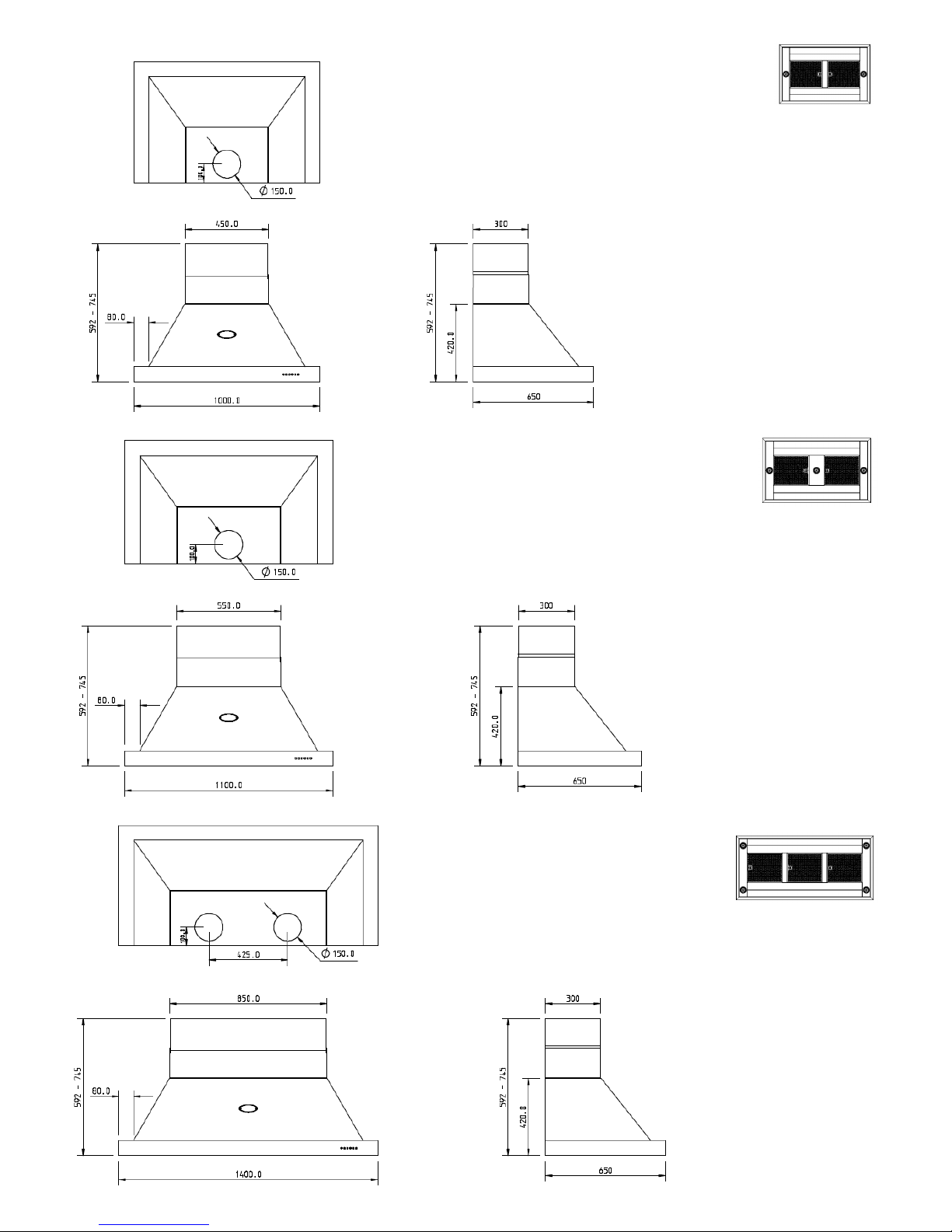
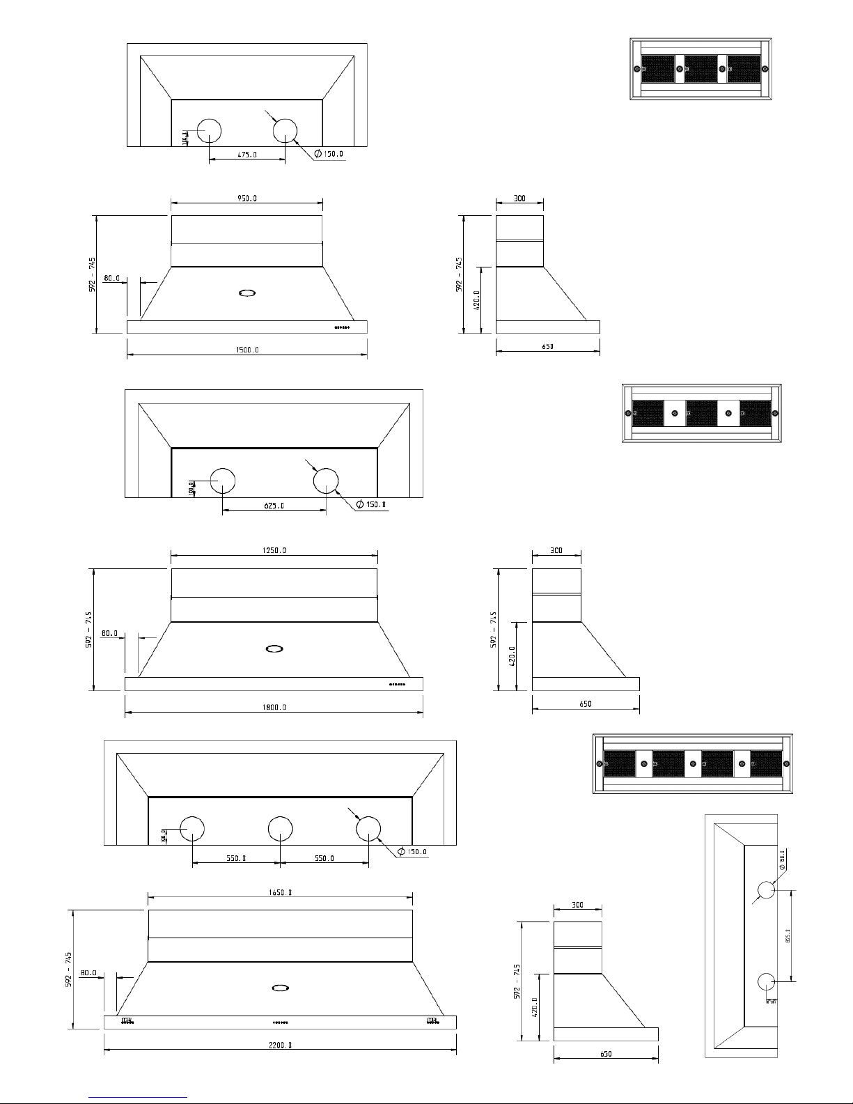
SECTION 8. HOOD DIMENSIONS
Page 3
FMH Range Hoods
W1103 Revision: 14/10/2011 3
SECTION 1. INTRODUCTION
Your range cooker is a semi-professional unit which gives you the power and
flexibility to realise your full potential in the kitchen. Inevitably, during the
cooking process, there will be heat, vapours and fumes produced. Your FMH
extractor has been designed to complement the range cooker both in looks
and performance in order to create the ideal environment for creative cooking.
SECTION 2. EXTRACTION PERFORMANCE
This hood is designed for ducting out, i.e. duct to an outside wall. To obtain
the best possible extraction performance use 150mm diameter ducting or
larger. Wherever possible utilise rigid circular pipe or a flat channel equivalent.
Avoid using flexible ducting (except for runs of less than 1.5m) as this is not
smooth on the interior and can cause air flow restrictions. Semi rigid ducting
can be used. Please note ducting kits and ducting components are optional
accessories and have to be ordered - they are not supplied with the hood.
The most important influence on the performance of the extractor is the design of the ducting which takes the exhaust air from the extractor to the outside wall louvre. The duct route should be a prime consideration during the
initial stages of the kitchen design. Please note the following:
The extractor is provided with a spigot suitable for connecting 150mm
diameter duct. *
Note: 150mm is the minimum duct diameter consistent with efficient
extraction.
The exhaust duct route length should be kept as short as possible with
as few bends as possible.
The most efficient configuration is to duct straight through an outside
wall so try to position the cooker against an outside wall when designing
your kitchen layout.
The hood can be vented either to the top exhaust or the rear exhaust
position. Use the position which gives the shortest duct route length and
least number of bends. (The blower will need to be rotated for ducting
directly through the rear exhaust position.)
A route with more than two 90
o
bends will significantly degrade the performance of the extraction system. If possible, avoid having a 90o bend
at the extractor exhaust spigot; keep bend radii as large as possible to
maintain a smooth airflow without vortices; avoid kinks in flexible ducting; pull flexible ducting taut over straight runs to ensure that the internal
surface is as smooth as possible.
Duct runs in excess of 5 metres are not recommended and will seriously
impair efficiency - if you are concerned then please call for advice.
SECTION 3. IMPORTANT INFORMATION
The following minimum headroom is required to accommodate the cooker
and hood:
The minimum distance between the range hob burners and the bottom of the
extractor is essential to prevent overheating of the extractor and its components.
If you are fitting a splashback then the cooker-to-hood clearance is dictated
by the splashback height (unless you choose to run the splashback down
behind the cooker). Splashbacks are best fitted before the hood.
Please also note that a 90o bend in the flexible ducting will require 215mm
minimum headroom to give a smooth radius with no kinking.
Requirements of the relevant authorities concerning the discharge of exhaust
air must be complied with.
Attention:
This appliance requires an earth connection.
Ensure that the supply voltage corresponds to that marked on the rating label
inside the extractor.
The extractor must be isolated from the electrical supply before carrying out
any cleaning or maintenance operations.
Pay particular attention to fire risk when frying. To minimise the risk of
fire, all instructions relating to cleaning the grease filters and removing
grease deposits must be adhered to.
Do not flambé under the extractor.
SECTION 4. INSTALLATION
Do not throw away the box and any internal packaging until installation
is fully completed - the packaging may be required in the unlikely event that
hood must be returned.
4.1 Remove the Grease Filters
Place extractor on its backplate on a horizontal surface.
To remove the grease filters pull/lift the filter release lever away from the
hood base. This releases the retaining clips allowing the filter to be carefully
lifted away from the hood. Take care not to scratch the hood.
The internal fixing holes, blower assembly and spigot blanking plate can now
be accessed through the opening in the baseplate. *
4.2 Blower Exhaust Position
The hood can be vented either to the top exhaust or the rear exhaust position. Each exhaust position has 4 fixing points onto which can be attached
either the blower assembly or a blanking plate. *
Position the blower assembly in the chosen exhaust position and the blanking
plate in the unused position using the original fixings and washers supplied .*
When changing the exhaust position, care should be taken not to excessively
pull or twist the cable attached to the blower.
4.3 Duct Installation
Make holes in the wall or ceiling to take the 150mm diameter ducting from the
extractor exhaust spigot to the outside. *
The exhaust duct route length should be kept as short as possible with as
few bends as possible - see Section 2.
An external weather louvre designed for connection to 150mm ducting or
larger should be used to terminate ductwork on an external wall - an airbrick
must never be used.
* 1400mm, 1500mm & 1800mm wide internal fan models have two sets
of blower assemblies and blanking plates. The 2200mm wide model has
3 blower assemblies. Each blower assembly has a separate exhaust
spigot for independent ducting to the outside - i.e. you must run 2 or 3
separate 150mm ducts.
FMHE Models supplied for connection to the high performance external
fan are supplied with two exhaust spigots fitted - two 150mm ducts
should be run to the external fan which has it’s separate installation
instructions.
Cooker-to-hood clearance (minimum):
Recommended clearance range
750 mm
800 - 850 mm
Hood height including standard chimney: 592 - 745 mm
Minimum ceiling height with standard chimney: 2242mm
The exhaust air must not be discharged into a flue which is used for exhausting
fumes from appliances supplied with energy other than electricity, e.g. oil or gasfired central heating boilers, gas-fired water heaters, etc.
Warning
The following is a requirement of UK and European legislation and
is in the interests of your safety.
If the room where the cooker hood is to be used contains a fossil fuel
burning appliance such as a gas or oil central heating boiler, then its flue
must be of the room sealed or balanced flue type. A ducted hood is not
suitable for use in a room where any open flue is in use, as dangerous
fumes of combustion can be sucked back in to the room. This would
include the following open flue appliances – central heating boilers, coal
fires, log fires, gas fires, wood burning stoves etc. Therefore, if you have
an open flue fossil fuel burning appliance in your kitchen, you are
automatically compelled to select a hood that is capable of working in
recycling mode.
FMH Range Hoods
Page 4
FMH Range Hoods
W1103 Revision: 14/10/2011 4
4.4 Fixing the Hood to the Wall
If you are fitting a splashback it should usually be fitted before the hood.
Note: The chimney can be removed to ease handling of the hood.
The supporting wall must be of good quality, have an even surface and be
sturdy enough to support the extractor.
Fixings must be used which are suitable for the type of wall construction.
Fixing the hood to the wall requires a minimum of 2 people.
No wall fixingsare provided.
Method
Note: Figures referenced in this section can be found on Page 3.
Mark a horizontal line (A) denoting the hood’s bottom edge - if you have
already fitted a splashback then the top edge of this will serve. A vertical
centre line up to the desired finished chimney height will also help you to
accurately position the hood and chimney bracket.
Remove the grease filters to gain access the internal fixing holes.
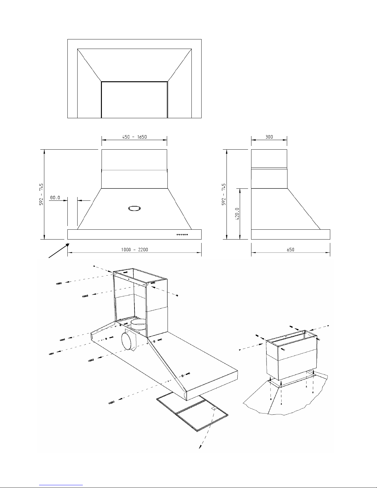
Mark the positions of the hood fixing hole centres, (see Figure 2 “Example of
universal hood fixing detail”. Note: This shows a typical hood installation and
is not intended to accurately represent the geometry of your hood.
Offer the hood up to the wall in the desired position and mark the wall
through the fixing holes in the hood rear. This is a 2 person job.
Mark and prepare a hole(s) suitable to accommodate 150mm diameter
ducting (160mm min). If using the rear exhaust spigot position then accuracy is critical - see Figure 1.
Secure the hood, using fixings suitable for the wall construction, in the
previously marked positions. This is a 2 person job.
Tip: for rear exit you may have to connect the ducting prior to fixing the
hood to the wall - rigid ducting is strongly recommended.
Unscrew the chimney bracket from the inner chimney and mark the positions of the chimney bracket fixing holes - the central hole is for viewing
your centre line (see Figure 3).
Tip: the bracket finishes flush with the chimney top. You may find it easier
to slide the chimney up to the desired height and mark the position of the
top corners—you can then line the top of the chimney bracket up with
these marks.
Secure the chimney bracket, using fixings suitable for the wall construction, in the previously marked positions (see Figure 3).
Connect the ducting and electrical supply cord as described in section 4.5
and 4.6.
Slide the inner chimney over the bracket and secure using the screws
previously removed.
4.5 Connecting the Ducting
Connect ducting to extractor exhaust spigot. You may find this easier with
the chimney removed. The chimney is attached using M4 machine screws
which can be accessed through the filter opening(s). For rear exit exhaust
positions the duct should be attached prior to fixing the extractor to the wall.
When the extractor is in position, check that the duct has not been flattened
or kinked along its route.
Connect the ducting to the wall louvre or alternative outside termination.
Secure the louvre to the outside wall. Ensure that any air fins are directed
downwards.
Refit the grease filters.
4.6 Electrical Installation
The extractor is a stationary appliance designed to be connected by fixed
wiring to the electrical supply. A competent electrical technician must perform the electrical installation.
The extractor must be fed from a 220—240Vac single phase electrical supply using a switched spur fitted with a 3A fuse. The spur should be located
such that the supply can be disconnected from the extractor using the switch
after installation (adjacent to the extractor/cooker is best). The means of
disconnecting from the supply must have a minimum contact separation of
3mm in all poles. Alternatively a means of disconnection in the fixed wiring
according to the relevant wiring regulations must be fitted.
A supply cord for connecting the extractor to the spur is included.
The mains supply is connected to the free end of this cord as follows:
SECTION 5. OPERATING INSTRUCTIONS
Switch power on at the fused spur.
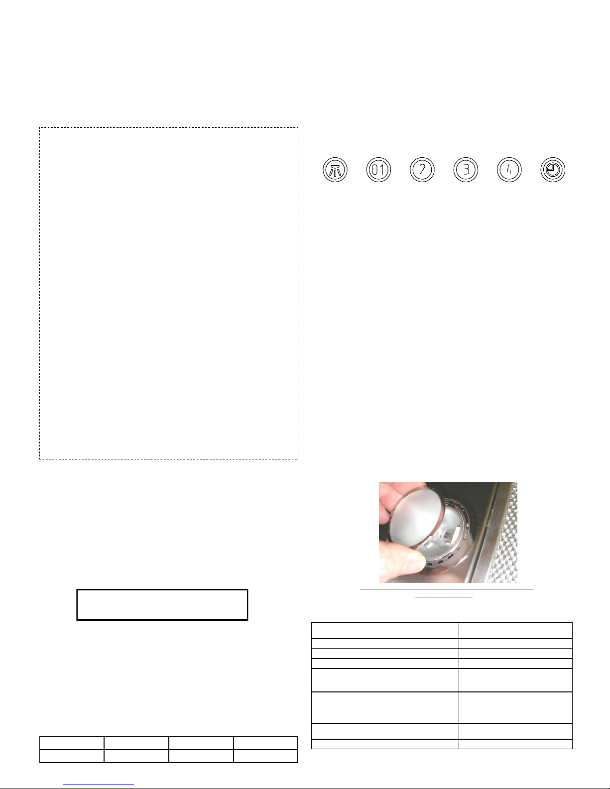
The extractor has 6 push-buttons which illuminate when selected.
Their functions are summarised below.
Note: 2200mm model has 3 sets of controls for independent control of each fan).
The extractor controller will automatically switch off the appliance if
there has been no operator action for 4 hours.
After 30 hours accumulated running GREASE FILTER SATURATION
will be signaled by all 6 indicators flashing. Reset by pressing Pushbutton FAN OFF (delay).
SECTION 6. MAINTENANCE
Regular maintenance is essential to ensure good performance and
long-life.
To clean the stainless steel surfaces of the extractor use a proprietary cleaning agent. Do not use abrasive cleaning materials or products.
Clean the grease filters in a dishwasher or by hand-washing in hot
water and detergent. Wash the filters at least every 2 months sooner if the extractor is used extensively.
To maintain the immaculate appearance of the extractor, and to minimise fire risk, ensure that grease deposits on the extractor surfaces
are kept to a minimum by regular cleaning.
Should you wish to clean the hood internally (accessed when the
filters are removed) then you must first isolate (switch off) the
electrical supply to the hood at the switched spur.
To access the halogen lamps for replacement prise off the chrome
ring immediately surrounding/retaining the frosted glass with a suitable flat implement (eg. screwdriver), taking care not to scratch or
damage the light assembly (see picture below). Only replace with
bulbs of the same type and rating as originally supplied (12V 20W
G4 LV halogen capsule lamp).
Light Assembly
SECTION 7. SPECIFICATIONS
ELECTRICAL HAZARD
DISCONNECT ELECTRICAL SUPPLY
BEFORE PROCEEDING FURTHER
LIGHTS ON/
OFF
FAN ON
SPEED 1
FAN OFF
(Immediate)
FAN ON
SPEED 2
FAN ON
SPEED 3
FAN ON
SPEED 4
FAN OFF
Delayed for
10 Minutes
to clear
fumes
Nominal airflow free air (internal fan)
Nominal airflow in free air (EC310 wall fan)
1,000 m3/hr
3,000 m3/hr
Supply voltage: 220-240V~ 50Hz
Halogen lamp voltage: 12V
Blower power input: 250W per fan
Halogen lamp power:
2 x 20W Single Fan
4 x 20W Twin Fan
5 x 20W Triple Fan
Total power:
290W Single Internal Fan
580W Twin Internal Fan
850W Triple Internal Fan
EC310 Wall fan models 610W
Fuse size for electrical supply:
3A Single Internal Fan
5A All other variants
Blower spigot diameter: 150mm
Core
Live Neutral Protective Earth
Core Colour
Brown Blue Green/Yellow
Page 5
FMH Range Hoods
W1103 Revision: 14/10/2011 5
Figure 2
Example of universal Hood Fixing Detail
SECTION 8. HOOD DIMENSIONS
Figure 3
Universal Chimney Detail
Notes
Two tone (painted) models have a stainless plinth section
and an enameled upper canopy and chimney.
Multiplefan models have multiple independent spigots for
connection to separate 150 ducts - see following pages..
Specific model details can be found on subsequent pages
Line A
Fourneaux de France Ltd
Unit 3 Albion Close, Newtown Business Park, Poole Dorset, BH12 3LL
Tel 01202 - 733011 Email [email protected] www.fdef.co.uk
Page 6
FMH Range Hoods
W1103 Revision: 14/10/2011 6
FMH 1000
FMH 1100
FMH/FMHE 1400
Page 7
FMH Range Hoods
W1103 Revision: 14/10/2011 7
FMH/FMHE 1500
FMH/FMHE 1800
FMH 2200
FMHE 2200 Remote Fan Version
 Loading...