

Page 1
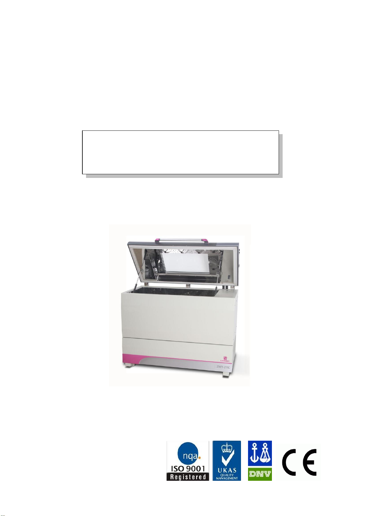
Economic Horizontal
Shaking Incubator
User’s Manual
This Manual applies to:
Modes: ZWY-111B , ZWY-211B ,ZWY-111G , ZWY-211G , ZWY-111C , ZWY-211C , ZWY-111D ,
ZWY-211D , ZWF-111 and ZWF-211
Page 2

Reminder
Prior to operation, this manual should be read thoroughly and completely
understood-as it might be helpful to master the operation techniques of this
unit.
Thanks !
Thank you very much for purchasing one of our economic shaking incubators, specially
designed for you-the lab professional. Your choice indicates that you have very high
requirements on style and performance of this type of incubators.
LABWIT shaking incubators have achieved a good reputation and trust among various clients
for its advanced temperature controlling technology, sound framework design, excellent
molded exterior and outstanding professional workmanship. These products have been
exported through most leading companies into European, American and East Asian markets.
The horizontal floor shaking incubators have a number of advanced specifications like an
intelligent precise control of temperature and shaking speed through the standard control
panel and solid operating safety features. This large floor model is available all with heavy
duty orbital shaking mechanisms that provide smooth start and quiet shaking motion under
maximum load with maximum speed.
This equipment is specially designed for the research experiment that involves microbiology,
pharmacy and agriculture. It is widely used for cell culturing, hybridization, cell aeration, and
solubility studies. Etc.
Since the date of your purchase of this product, after-sale service will always be close to you
through your local dealer and/ or the importing company of your region.
Anyhow, no matter what questions you have using our equipment; please do not hesitate to
contact us whenever you want.
LABWIT thanks you for your trust in this product!
Safety instruction!
Plea Safety instruction!
Please be sure to follow the instructions, which are really important for your safety.
se be sure to follow the instructions, which are really important for your safe
1
Page 3
Danger!
Warnings against injury and damage.
Safety instruction!
Please be sure to follow the instructions, which are
important to your safety.
1. The electrical supply circuit to the incubator must confirm to all national and local electric codes.
Check the serial-data plate for voltage, cycle, phase and amperage requirements before you connect
the unit.
2. Only use grounded power source (outlet) to avoid an electric shock or fire, and it is recommended
that the equipment has an unobstructed access to a dedicated power source.
3. In case of a problem, do not attempt to repair the product yourself. Do not open the power box to
avoid electric shocks.
4. Do not pull out the plug when the unit is in use. Never drag on the wire to unplug the unit.
5. This equipment can sustain a maximum of ±10% nominal voltage fluctuation; Otherwise a power
stabilizer is needed.
6. A surge protector is recommended to avoid power-related faults.
7. In case of malfunction or burning smell, the unit must be unplugged immediately. Use a circuit
breaker to cut off the power supply. Continuance of abnormal state will result in fire caused by
overheating.
8. The electric power supply must be cut off in following situations:
8.1.-When opening the door of electrical power box without cutting off power supply might result in
electric shock.
8.2.-When replacing the fuse. Replacing the fuse without cutting off the power supply will probably
result in electric shock.
8.3.-When a malfunction occurs, mishandling will result in further damage of the equipment or
accidental injury to the user(s).
8.4.-If you do not use the unit for a long period of time.
9. Never touch the glass door and/or inner chamber when the incubator is hot.
0
Page 4
Clean the shaking incubator before you put it into use and on a
regular base.The interior should be wiped down with an appropriate
disinfectant, such
as 70 % ISOPROPYL ALCOHOL or equivalent.
DO NOT USE ANY CHLORINATED OR HALOGEN MATERIAL-
AS THIS IS HARMFUL TO THE POLISHED STAINLESS STEEL !!!
Attention!
Instructions for optimal performance
1. Before starting your equipment, the unit must be placed horizontally on a solid, flat floor, and
elevated and leveled with four foot blocks.
2. The incubator needs even heat lost on all surfaces in order to maintain small internal temperature
variations .As a result, a minimum of 20 cm must be allowed between the rear and sides of the
incubator to any obstructions.
3. Do not locate the unit exposed to direct sunlight or near heating /cooling ducts.
4. The unit must be kept away from electromagnetic interference sources.
5. Flasks placed inside the shaking incubator should be placed to avoid (as much as possible)
imbalance on the shaking platform
6. Slam the door(s) will probably leads to damage of the equipment.
7. When in operation (the platform is still moving), do not open the lid (too much or too long) as this
might affect the temperature inside.
8. The incubator must be kept away from volatile, flammable, explosive liquids or gases
9. Please keep the chamber clean. Regular cleaning is required.
Extra for refrigerated units:
10. After transport of this Shaking Incubator –DO NOT USE IT for at least 24 Hours, unless you are a
100% sure that the unit has been moved in an upright position only.
11. To extend the compressors life and to maintain an excellent performance of your refrigeration
system, the condenser of the unit should be cleaned every month.
1
Page 5

Table of contents
1. Performance Parameters _________________________________________ 3
2. Technical Specifications _________________________________________ 4
3. Control Panel __________________________________________________ 5
4. Preparation and Start-up _________________________________________ 7
5. Control Mode & Clock Checking ___________________________________ 8
6. Temperature Retaining Switch Setting ______________________________ 8
7. Temperature, Speed, Timer Settings _______________________________ 9
8. Date & Time Settings ___________________________________________ 10
9. Temperature & Speed Alarm Settings _____________________________ 11
10. Refrigeration & Defrost Settings ________________________________ 12
11. Temperature Calibration _______________________________________ 14
12. Non-volatile memory function Setting____________________________ 15
13. Setting of communication address for RS485 connection (Opt) ______ 15
14. Sum Run Time Checking ______________________________________ 16
15. Operation and Switch off ______________________________________ 16
16. Shaking Diameter Adjustment __________________________________ 17
17. Trouble Shootings ___________________________________________ 18
18. Electronic Control System _____________________________________ 20
19. After-Sale Service. ___________________________________________ 21
2
Page 6

1. Performance Parameters
Both the interior and exterior are made of robust materials for lifetime operations. The inner
chamber is made of high quality #304 stainless steel sheets, with 4 round coved corners. All
exposed edges are de-burred to insure no sharp edges. The exterior is cold rolled steel finished
with powder coated polyurethane finish, which is resistant to most chemicals and easily cleaned
with mild household detergents.
The ZHICHENG shaking incubator’s microprocessor control system uses fast responding PT 100
sensors which commands and executes a special control algorithm that energizes a solid-state
switch to supply power to the heaters.
The control electronics are protected trough a circuit breaker that may trip at 110% of loading rate,
but will trip within 1 second at 150% of load rating.
The compressor (in refrigerated units only) has an independent overload protection.
CFC-free refrigerant which causes no damage to ozone layer.(Applies on ZWY-2/ZWF-2 models)
Large doublefold tempered glass window and flourecent light, provide complete visibility of
chamber interior.
Models ZWY-111D and ZWY-211D are equipped with foot pedal for lid opening even when
carrying full loads in both hands.
LCD display presents all actual and (pre)set parameters.
Electronic timer, from 0 – 9999 Mins, automatic stop, audio/ visual alarm.
Password protection against unauthorized change of parameters.
Audible and visual alarms for motor temperature and set point deviations
Non-violate memory for set point retention after a power interruption.
“Long-Life” brushless AC motor creates a smooth, quiet and uniformed shaking motion
High capacity for up to 5L flasks (except ZWY-111B/211B, ZWF-111/211)
Option: unit equipped with RS-485 interface communication can be connected to local network so
that remote data logging and control can be achieved via laptop/ PCs.
3
Page 7
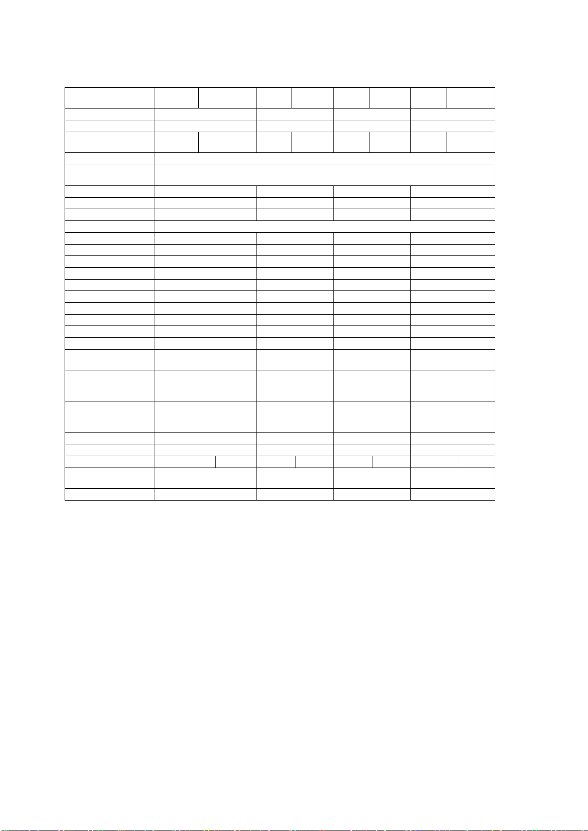
2. Technical Specifications
Model
ZWY-
111B
ZWY211B
ZWY-
111C
ZWY-
211C
ZWY-
111D
ZWY-
211D
ZWF-
111
ZWF-
211
Volume (L)
170
260
300
300
Mode
Orbital
Orbital
Orbital
Reciprocal
Temperature (°C)
A+5 to
60
4 to 60
A+5
to 60
4 to 60
A+5
to 60
4 to 60
A+5
to 60
4 to 60
Temper. Accuracy
±0.1℃
Temper.
Uniformity
≤±1℃@37℃
Tray (mm)
920x500
920x500
940x584
896x530
Stroke (mm)
26
26
26
1 to 50 stepless
Speed (rpm)
30-300
30-300
30-300
30-240
Capacity *
*Glass dimensions may reduce max.capacity
50ml
64
82
82
66
100 ml
64
82
82
66
250 ml
40
45
52
45
500 ml
28
33
38
32
750 ml
23
24
26
23
1000 ml
15
15
22
15
2000 ml
-
11
12
11
3000 ml
-
8
11
11
5000 ml
- 6 6
6
Test tube 18ml
208
208
208
208
Inner dimensions
(mm) (WxDxH)
975x565x305
975x565x465
1005x655x435
975x565x515
Exterior
dimensions (mm)
(WxDxH)
1200x740x800
1200x740x1000
1260x830x1000
1200x740x1070
Packing
dimensions (mm)
(WxDxH)
1320x860x970
1320x860x1170
1380x960x1170
1320x860x1170
Net Weight (kg)
159
168
248
201
Gross Weight (kg)
200
213
298
242
Power (W)
800
1050
950
1150
1550
1800
950
1150
Electricity
220/240Volt
50/60 Hz
220/240Volt
50/60 Hz
220/240Volt
50/60 Hz
220/240Volt
50/60 Hz
Approval
CE, ISO
CE, ISO
CE, ISO
CE, ISO
4
Page 8
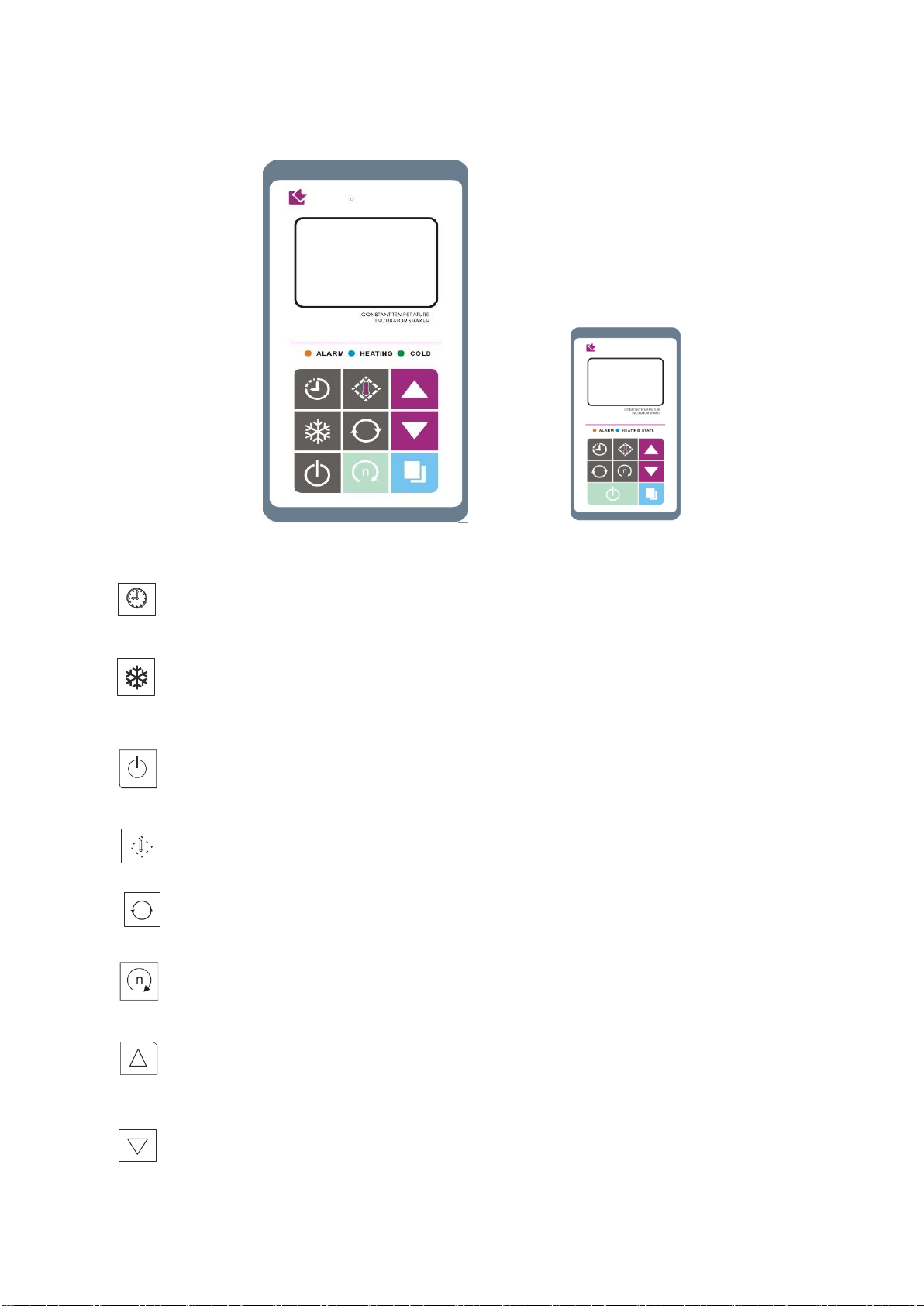
3. Control Panel
Cooling Model Heating Only Models
Time button:
Button to display the preset time and the status of the power-off recovery function.
Press again to display the remaining time (if Timer is set).
Press it to stop the acoustic alarm when needed
Refrigeration status button (Refrigerated unit only)
Button to display the current refrigerating parameter, defrost timer and the defrost period in
turns.
Power button:
Hold this button for 2 seconds to turn the unit on/off the standby mode
Temperature button:
Press this button to display the actual temperature value and the set temperature in turns
Speed button:
Press this button to display the actual speed value and the set speed in turns
Start/Stop button:
Button to start or stop current operation
Increase button:
Press this button and the parameter will increase by one digit, the parameter will keep
increasing while this button is held.
Decrease button:
Press this button and the parameter will decrease by one digit, the parameter will keep
decreasing while this button is held .
5
Page 9

Set/Confirm button:
ALARM
HEATING
COLD
Press this button to enter the menu of setting, press it at the end of the setting to save and
exit.
Temperature alarm indicator:
When the temperature inside the chamber is deviated over the preset alarm limit , the
indicator flashes and the alarm beeps
Heating indicator:
When the heater is connected with power supply, this indicator will be light. This indicator will
twinkle when the real temperature close to the preset value
Refrigeration indicator:
Lights when the cooling system is switched on to cool down the inner chamber.
6
Page 10
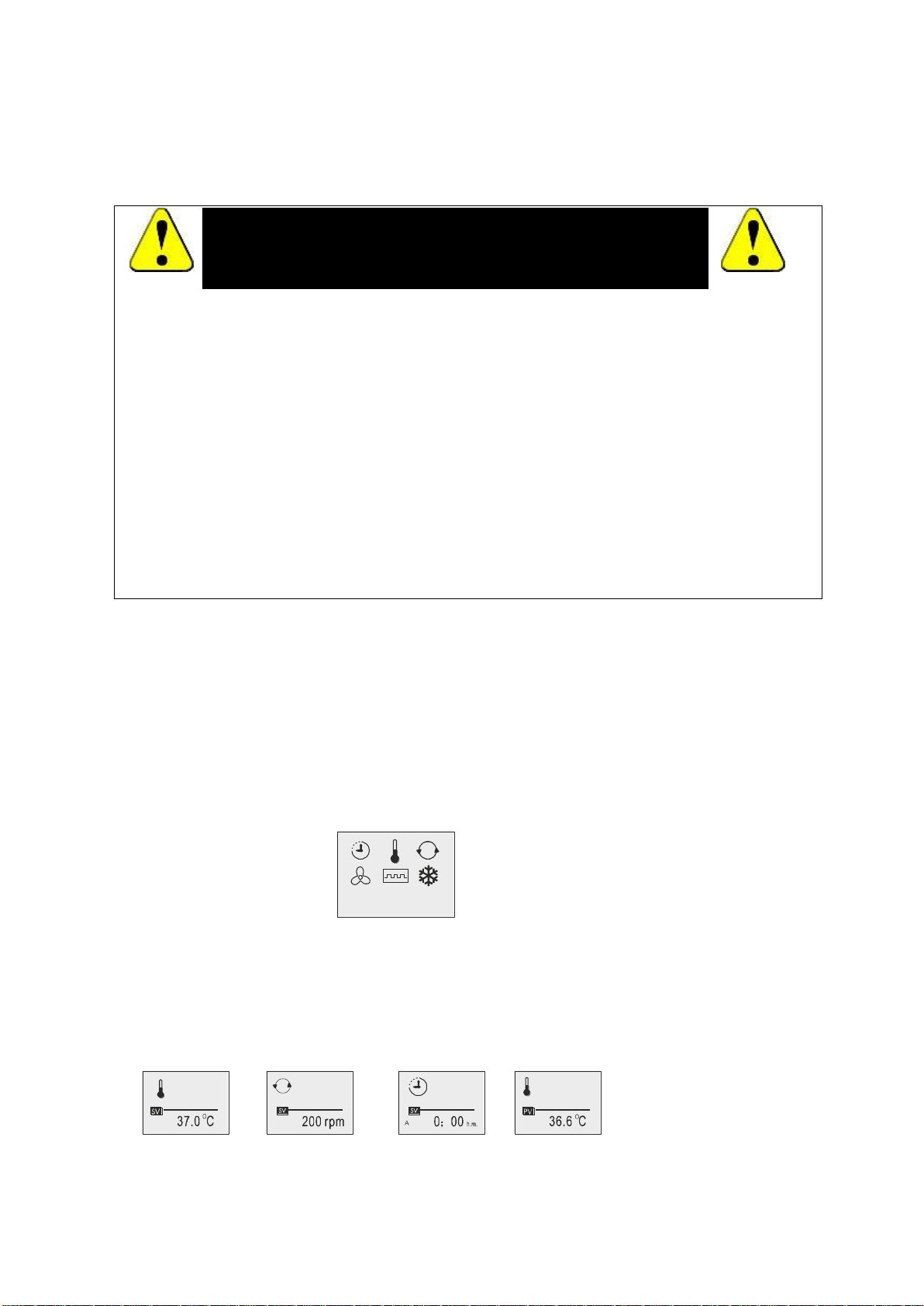
4. Preparation and Start-up
Preset
Temperature
Preset
Shaking Speed
Timer
Function
Measured
Temperature
Incubator
Shaker
Safety instruction!
Please be sure to follow the instructions, which are really important for
your safety.
4.1 Before starting your equipment, the unit must be placed horizontally on a solid, flat floor, and
elevated and leveled with four foot blocks. The foot blocks are provided to level as well as “fix” the
unit firmly on the floor. To allocate the blocks in position, please do strictly follow the procedures:
4.1.1 Lift the front below cover and take it off. (If ZWY-211B/111B, please skip to “Section
4.1.2”.)
4.1.2 Unscrew up the adjusting bolt on the front-left corner.
4.1.3 There is one hole on each of the other three corners of base of the unit, locate each of
them.
4.1.4 Tilt or push the unit from its front side, and at the same time, another person is needed to
lay the foot block underneath the hole, whose hands must be off the unit before the unit is
laid down! Do be careful of your hand!
4.1.5 Lay down the unit and see whether the tip of the block sits firmly in the hole. If not, please
re-do the “Section 4.1.4” again. Then lay the other one on the same side.
4.1.6 Lay the rest two blocks on the back side of the unit.
4.1.7 Keep unscrewing / screwing the adjusting bolt on the front-left corner with the spanner
until the unit is elevated leveled and sits firmly on the four blocks.
4.2 The shaking mechanism of all reciprocal shaking incubator (ZWF-111/211) needs filled up with
Lithium base oil before operation. To do so, remove the front below cover of the outer case, open
the lid, and remove the shaking tray so that the whole shaking mechanism can be seen. Then
pump the oil by pushing down the bar handle, until seeing the oil overflowing from the holes on the
shaking mechanism. Pump the oil frequently to ensure smooth shaking movement.
4.3 Turn the main switch which is located on the right side of the unit, power is applied to the
Unit and the LCD display shows:
-Incubator Shaker
-Pre-set Temperature
-Pre-set Speed
-Pre-set Time
4.3 The screen in turns displays the operating parameter stored in the equipment:
Preset temperature; Preset speed; Preset time; Real temperature.
And now, the microprocessor system has started controlling the temperature according to the
preset value.
7
Page 11
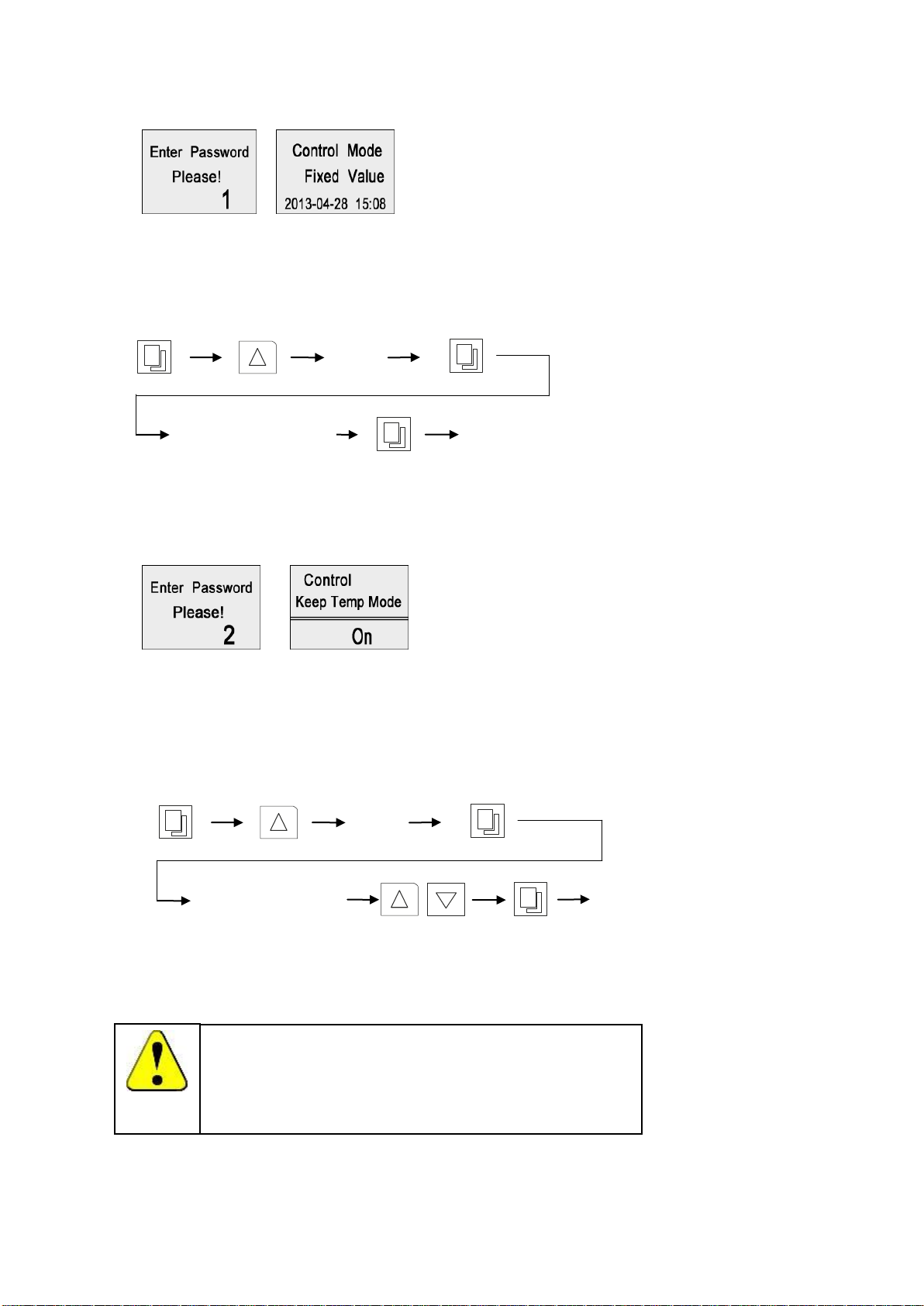
5. Control Mode & Clock Checking
1
Display current control
Exit
2
Display current status
of the temperature
retaining function
Exit
Special Attention!
When the status is "on", the temperature will remain under control at
its preset value even when shaking operation has been turned off
manually or by timer. Otherwise, when the status is "off", the system
will stop both shaking motion and temperature control when
operation is stopped.
5.1. Press "Set/confirm", press the "Increase" button to "1", then press the "Set/confirm" again. The
screen shows the current control mode and current date & time.
5.2. Press "Set/confirm" to exit to the home page
6. Temperature Retaining Switch Setting
6.1. Press "Set/confirm", press the "Increase" button to "2", then press the "Set/confirm" again. The
screen shows the current status of temperature retaining (Keep Temp Mode) function, press
"Increase" or "Decrease" to change the setting.
6.2. Press "Set/confirm" to exit to the home page
8
Page 12
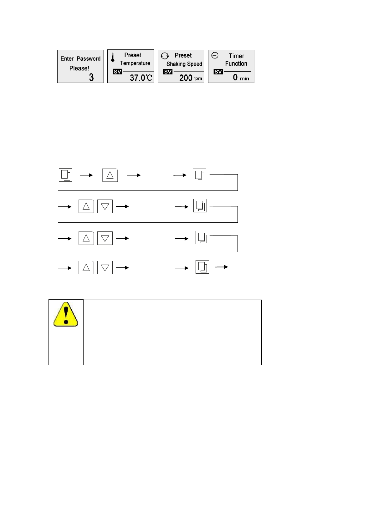
7. Temperature, Speed, Timer Settings
Special Attention!
1. This unit is equipped with "door switch". The temperature control
(main heater) will be temporarily disabled when lid is opened.
Therefore, always close the lid in time to avoid exceeded heat loss.
2. The timer can be set within 0-9999mins, the unit stops running
when timer is due. Acoustic alarm can be muted by pressing the
"Time" button.
3
Set
Temperature
Exit
Set Shaking
Speed
Set Timer
7.1. Press "Set/confirm", press the "Increase" button to "3", then press the "Set/confirm" again. The
screen shows the current temperature preset value, press "Increase" or "Decrease" to change the
value; press "Set/confirm" to save and switch to speed page, press "Increase" or "Decrease" to
change the value, and press "Set/confirm" again to save and switch to the timer page, press
"Increase" or "Decrease" to change the value if necessary. If Timer is set as "0", the unit will
keep running continuously.
7.2. Press "Set/confirm" to exit to the home page
9
Page 13
4
Set Time Clock
Exit
Set Year
Set Month
Set Date
8. Date & Time Settings
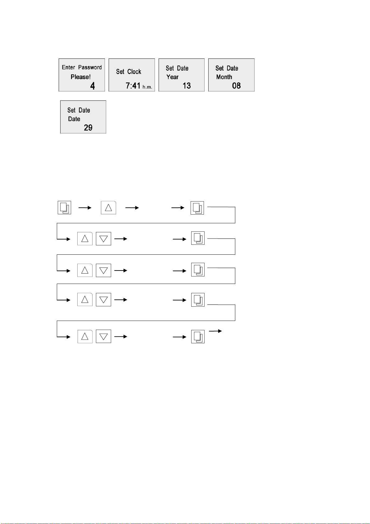
8.1. Press "Set/confirm", press the "Increase" button to "4", then press the "Set/confirm" again. The
screen shows the current time clock, press "Increase" or "Decrease" to change the time; press
"Set/confirm" to save and switch to "year" setting page, press "Increase" or "Decrease" to set the
year, and press "Set/confirm" again to save and switch to the "month" page, repeat the above
steps to set "month" and "date".
8.2. Press "Set/confirm" to exit to the home page
10
Page 14
9. Temperature & Speed Alarm Settings
Special Attention!
1. Deviation alarms can only be activated when unit is running, and
once actual temperature or speed has reached its preset value and
stabilized for a certain period of time.
2. Deviation alarm is activated when the actual parameter value
exceeds preset value±preset deviation alarm value. The "Alarm"
indicator is lighted, but can be muted by pressing "Run/Stop" button.
3 Deviation alarm can be automatically deactivated once if the
parameter value is back within the deviation tolerance range.
5
Set
Temperature
Deviation
Exit
Set Speed
Deviation
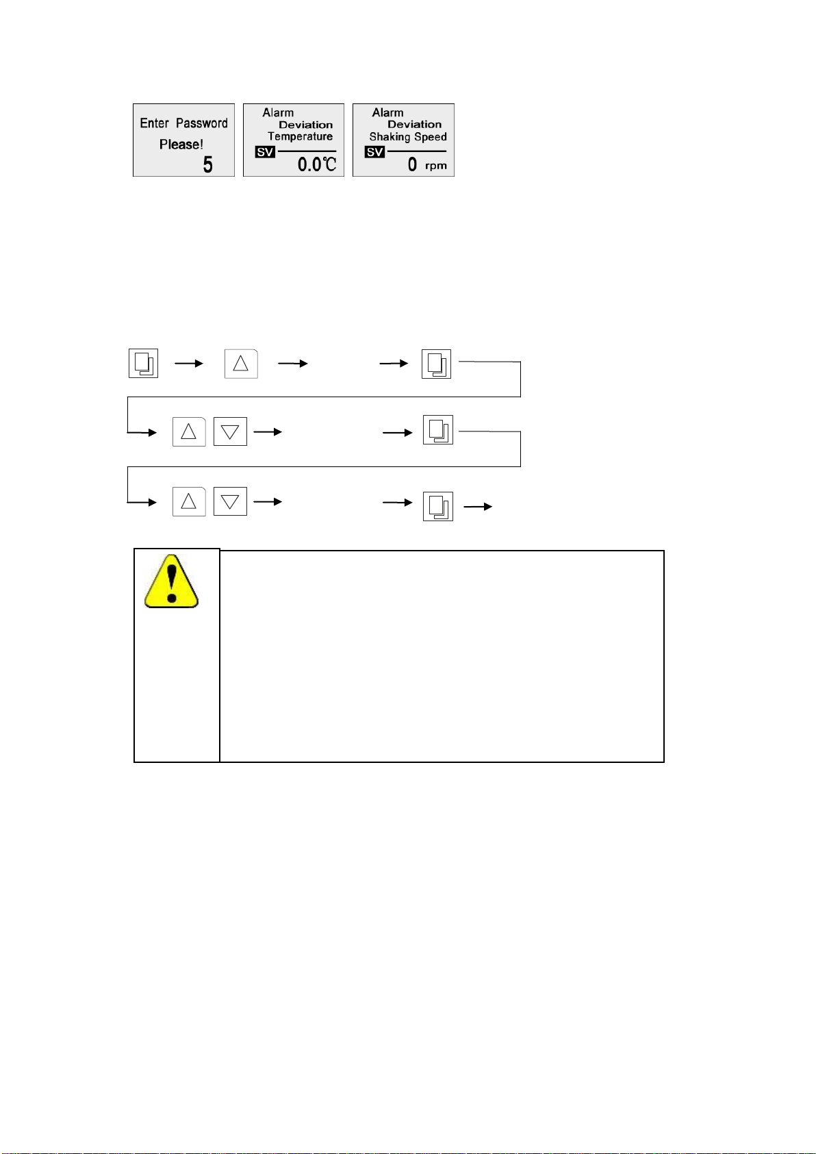
9.1. Temperature and speed alarm is activated when temperature or speed is deviated over limit. The
deviation alarm limit can be preset as below,
9.2. Press "Set/confirm", press the "Increase" button to "5", then press the "Set/confirm" again. The
screen shows the current "temperature deviation" value, press "Increase" or "Decrease" to change
the value; press "Set/confirm" to save and switch to "speed deviation" setting page, press
"Increase" or "Decrease" to change the value.
9.3. Press "Set/confirm" to exit to the home page
11
Page 15
6
Set
Refrigeration
Function
Exit
Set Defrost
Timer
Set Defrost
Period
10. Refrigeration & Defrost Settings
(Only for refrigerated models)
This unit is equipped with automatic and manual defrosting functions. With proper settings of
refrigeration function and auto-defrosting cycle, this unit can be used for continuous operation at low
temperature settings. Please note defrosting function will only be activated when actual temperature at
10℃ or below.
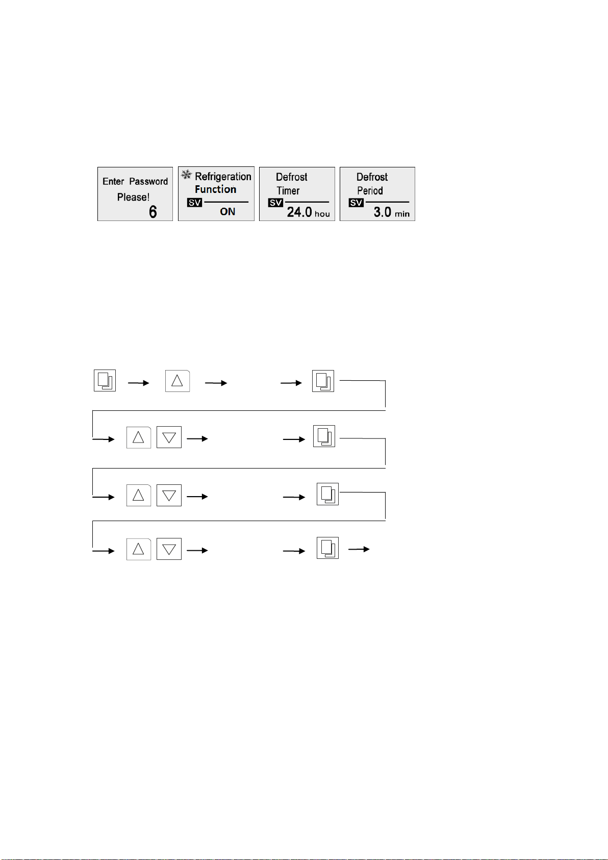
10.1 Press the "Set/Confirm" button, then press the Increase button to “6”, next press the "Set/Confirm"
button to display the preset refrigeration function on the screen, SV flashes. Press the "Increase"
or "Decrease" button to switch the refrigeration function "On/Off" .
10.2 Press "Set/Confirm" to confirm setting and enter the page of defrost timer setting, press "Increase"
or "Decrease" to set the time interval between two defrosting cycles. Set range from 1-240 hours.
10.3 Press "Set/Confirm" to confirm setting and enter the page of defrost period setting. Press
"Increase" or "Decrease" to set the time length of each defrost cycle. Set range from 1-24 minutes.
10.4 When setting is finished, press the Set/Confirm button to confirm and store the changed value.
10.5 Explanation for setting auto defrosting cycle:
a) "Defrost Timer" is the time interval between two cycles. For example, if this is set as "6", the
unit will defrost once every 6 hours.
To find out the suitable "defrost timer" setting, the frosting time duration should be counted from
start of the low-temperature operation to the point that the actual temperature start bouncing up
due to the frosting inside the evaporation chamber. Then set the "defrost timer" as somewhere
between 1/10-1/5 of the frosting time duration. For example, if the frosting time duration is 20
hours, the "defrost timer" can be set from 2-4 hours. High relative humidity will require more
frequent defrosting cycle.
b) "Defrost Period" is the time duration of each defrosting cycle. For example, if this is set as "3",
the unit will run a defrosting cycle for 3 minutes.
When the ambient temperature is higher than 25℃, like in summer, the recommended setting
is 30 seconds, otherwise, 1 min is considered as adequate. As ambient conditions may vary,
therefore, always try to find the most appropriate settings for your own particular ambient
condition.
12
Page 16
Attention:
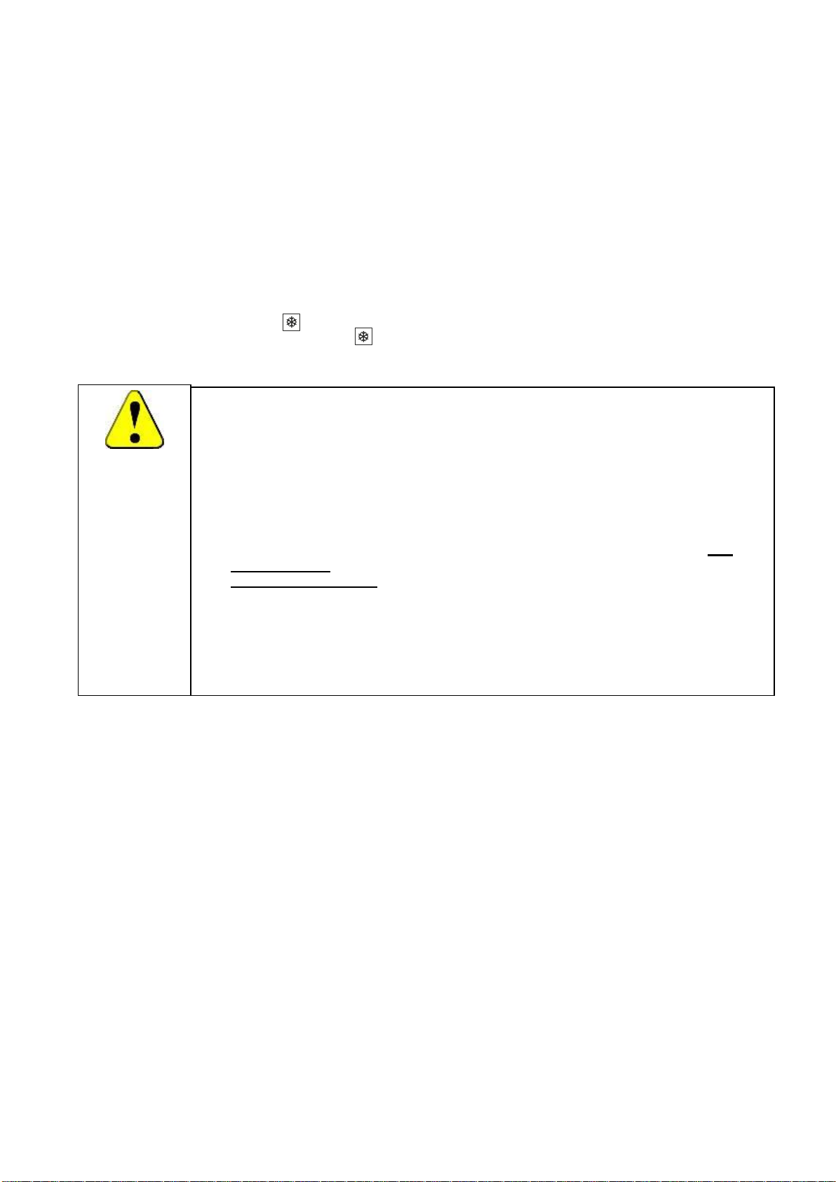
1. The defrosting cycle will only be activated when the following requirement is fullfilled;
Auto defrosting cycle: when both set and actual temperature is at or below
10℃;Manual defrosting cycle: when actual temperature is at or below 10℃.
2. The cooling system keeps running during defrosting cycle, while the motor fan stops.
3. The temperature will silently overshoot during defrosting, and then be stabilized when
defrosting terminates.
4. For better temperature control during continuous low temperature operations,
for example, below 10.0°C , the following operations are recommended: Set
Defrost Timer: “3” hr, Defrost Period: “0.7” min;
Weekly maintenance: Open the door and wipe off the condensation, set the
temperature at top value “65°C” and let it run for at least 1 hour to further
evaporate the condensations inside the chamber.
5. During defrosting cycle or heating up process, the drip tray should be place at the
unit's rear end and emptied on a regular basis.
Alternatively, if the set temperature is not so low as critical, in most cases, manual defrosting
will be adequate.
c) The proper of defrosting cycle can vary upon actual environmental conditions, preset
temperature value and running time. We recommend defrost at least 1-2 times per day, with
3-5 minutes for each cycle.
d) If after a defrosting cycle, there is still some ice inside the evaporator chamber (normally by
long term, low temperature operation) the “defrosting timer” needs to be shortened and/or the
“defrosting time” must be extended accordingly.
e) During the defrosting process, the actual temperature inside can have a temporary deviation of
3°C to the set point. This is normal, so does not require any action.
10.6 Explanation for setting Manual Defrosting cycle:
Alternatively, during the operation, the unit can run a manual defrosting cycle when necessary. To
activate the cycle, press button and hold for 3 seconds, the unit will start manual defrost for set
"defrosting period". To abort, press button and hold for 3 seconds. Minimum time interval
between two manual defrost cycles is 1 min.
13
Page 17
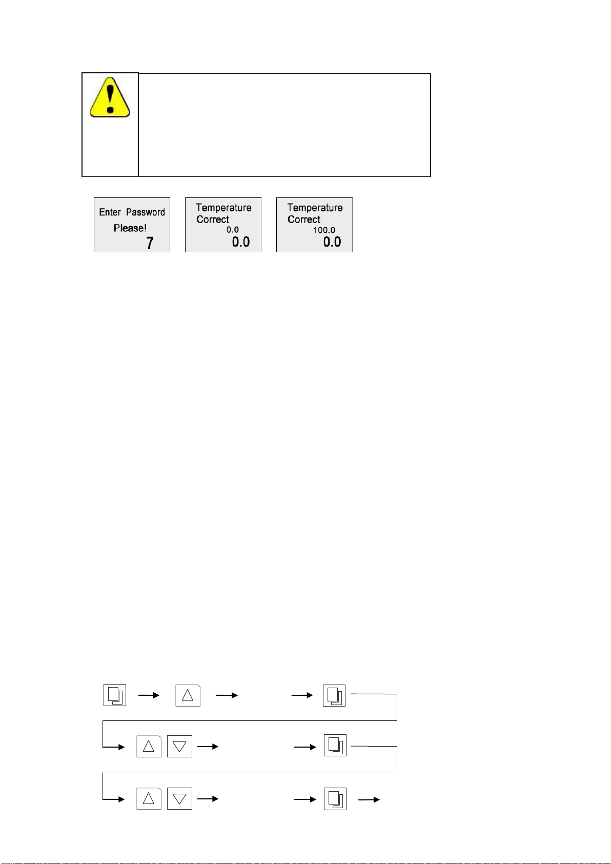
11. Temperature Calibration
Special Attention!
Temperature of each unit has been carefully calibrated in factory
before dispatch.
No further calibration is needed. But if it does, do follow the
calibration process strictly or consult your supplier, as wrong
operation can interfere the temperature accuracy significantly.
7
0.0 Point
Calibration
Exit
100.0 Point
Calibration
To calibrate the temperature, take a certified calibrated thermometer in a small bottle with
glycerin and place that in the geometrical center of the incubator.
11.1 Low Temperature Point Calibration (0.0)
a) Change the set point to lower temperature value, 37°C for HEATING ONLY UNITS (or 8°C for
REFRIGERATED UNITS,) and let the incubator run for at least 1 hour– until the temperature is
constant, and let the temperature inside of the chamber uniform.
b) Read the temperature on the thermometer through the glass lid; calculate the difference with
actual displayed temperature. for example, if reading is 35°C , difference would be 35-37= -2°C ,
while if reading is 38°C , the difference would be 38-37=1°C
c) Press the "Set/Confirm" button and go with the up arrow to code “7”. Press the Set/Confirm
again, to enter the Step 1. "Low Temperature Point Correction (0.0)", the display shows the
"Temperature Calibration" with "0.0" and the "Current Calibration Value". Use the up and/or
down key to make a further adjustment on the current correction value by the temperature
difference calculated above, for "-2°C ", decrease by 2, for "1°C ", increase by 1.
d) Keep pressing "Set/Confirm" button, skip the " High Temperature Point Correction (100.0)"
setting, save and exit.
e) The displayed temperature should have changed due to the calibration. Waiting for another
one hour to let the temperature stabilize again at 37°C , and check the thermometer value again,
and calculate the new difference.
f) if necessary, perform the calibration again until the actual display value equals to the calibrated
thermometer value. Thus the Step 1. "Low Temperature Point Correction (0.0)" is completed.
11.2 High Temperature Point Calibration (100.0)
a) If the incubator is to be used for more than one temperature setting, and "High Temperature
Point Calibration (100.0)" needs to be performed as well.
b) Change the set point to a higher temperature point as required, for example 60.0°C and let the
incubator run for at least 1 hour– until the temperature is constant, and let the temperature
inside of the chamber is uniformed
c) Change the enter the code "7" again and press "SET" skip the "0.0", and enter the "100.0"
page.
d) Repeat the same procedure, like the "Low Temperature Point Calibration", to correct the high
temperature point, until the display value equals to the actual thermometer value. Then the
"Step 2 High Temperature Point Calibration (100.0)" is completed.
14
Page 18
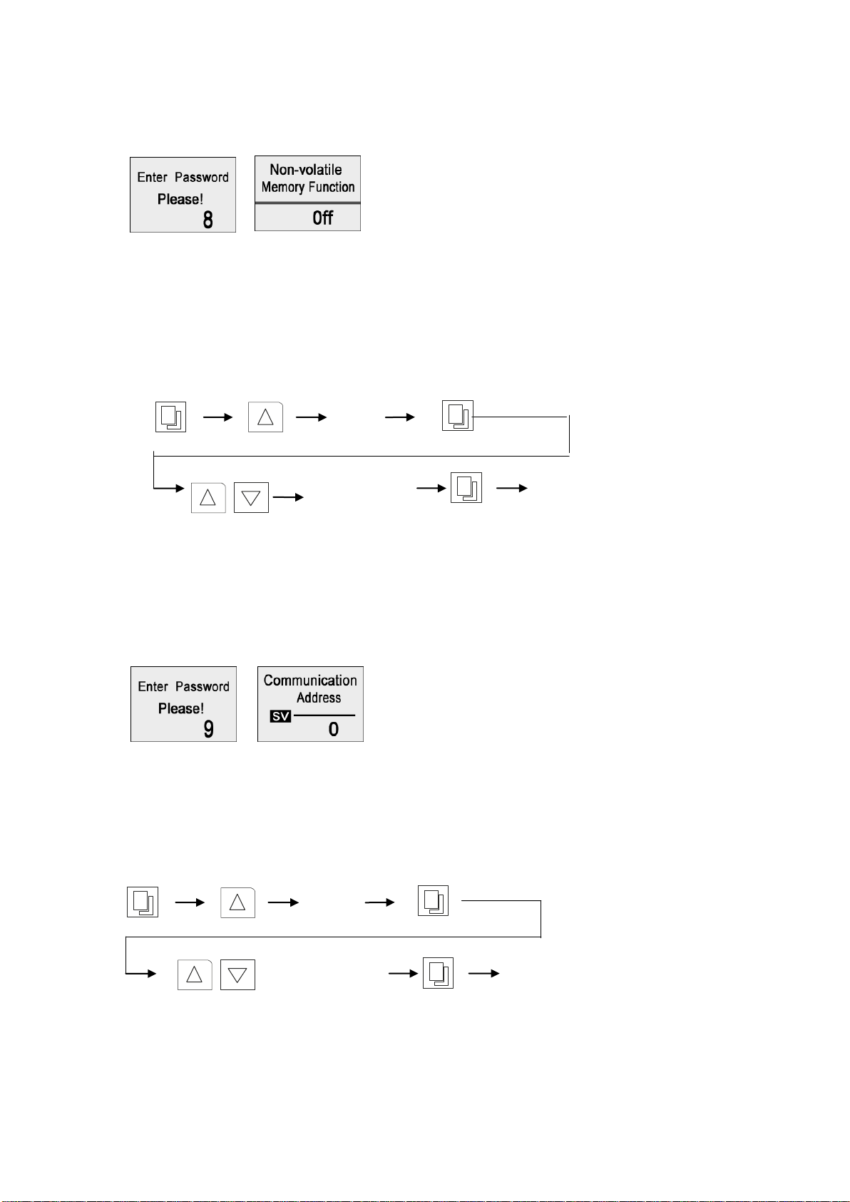
12. Non-Volatile Memory Setting
9
Set Communication
Address
Exit
8
Non-volatile
memory function
On/Off
Exit
If the non-volatile memory function is active (ON), the unit will run to the originally temperature,
speed and time program when the external power is recovered after a power failure.
12.1 To set the non-volatile memory function, first press the, then press the Increase button to “8”, next
press the "Set/Confirm" button and the screen will display the character ON or OFF. Press the
"Increase" or "Decrease" button to change the parameter and press the "Set/Confirm" button to
save the change and exit.
12.2 Press the Timer button, if the symbol “A” is displayed on the lower left corner of the screen, it
means the non-volatile memory function has been active.
13. Setting of communication address for RS485 connection (Opt)
If the RS-485 communication kit is equipped on this product, please follow the instructions below
for address setting.
13.1 Press the Change/Confirm button, then press the Increase button to "9", press the
Change/Confirm button again to enter the "communication" address setting page.
13.2 The screen displays the current communication address, and use Increase or Decrease button to
change the address, within the range of 0 to 63
13.3 Press the Change/Confirm button to save and exit
15
Page 19
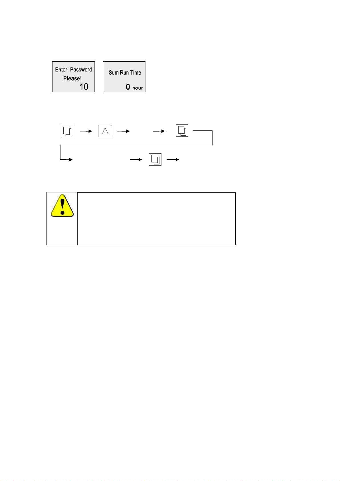
Special Attention!
The communication address is used as an identifying code for
each unit to pair with the software of the PC terminal. Each
communication code must be connected to only one unit. Different
communication addresses must be used if multiple units are to be
connected to the same PC terminal.
10
Check Sum Run Time
Exit
14. Sum Run Time Checking
The total run time of current operation can be checked via following steps. Run time starts
counting once "Start/Stop" button is pressed, and stops when pressed again.
14.1 Press "Set/Confirm" button and press the "Increase" button to "10", then press "Set/Confirm"
button again to see "Sum Run Time".
14.2 This is the accumulated time of current operation, which cannot be changed.
15. Operation and Switch off
15.1 When all the above settings are done, press the Start/Stop button and the equipment will run
according to the stored settings.
15.2 When during operation, the Start/Stop button is pressed, the platform stops from shaking
temporarily. The operation time remains on hold.
15.3 Press the Start/Hold button again to resume operation, the pre-set time starts to count down from
the remaining time when the operation was stopped.
15.4 When during operation, if the Start/Stop button is held on, within 3 seconds the remaining
operating time will be cleared to zero. Press the Start/Stop button once more, and the unit starts
again to count down from the preset operation time.
15.5 While the unit is in use, the current remaining operating time cannot be changed. If however
changed at this time, it is invalid with the current operation. Only when the current operation has
passed or stopped according to the above method, only if the instrument is re- started the new
changed value will be effective.
15.6 The equipment can be turned off by holding on the Power button on the control panel for 2
seconds. At this time, the control board is still connected to the power supply, so the main switch
on the right side of the equipment must be shut off to end operation completely.
16
Page 20
Special Attention!
Power supply must be disconnected before performing the following
operations!
Special Attention!
The maximum shaking speed should decrease when the shaking stroke
is increased. Generally speaking, Max speed not exceed 200rpm at
30mm stroke, 150rpm at 40mm stroke, 120rpm at 50mm.
ZHICHENG is not liable for any damages, as a result of not comply with
the speed limits above.
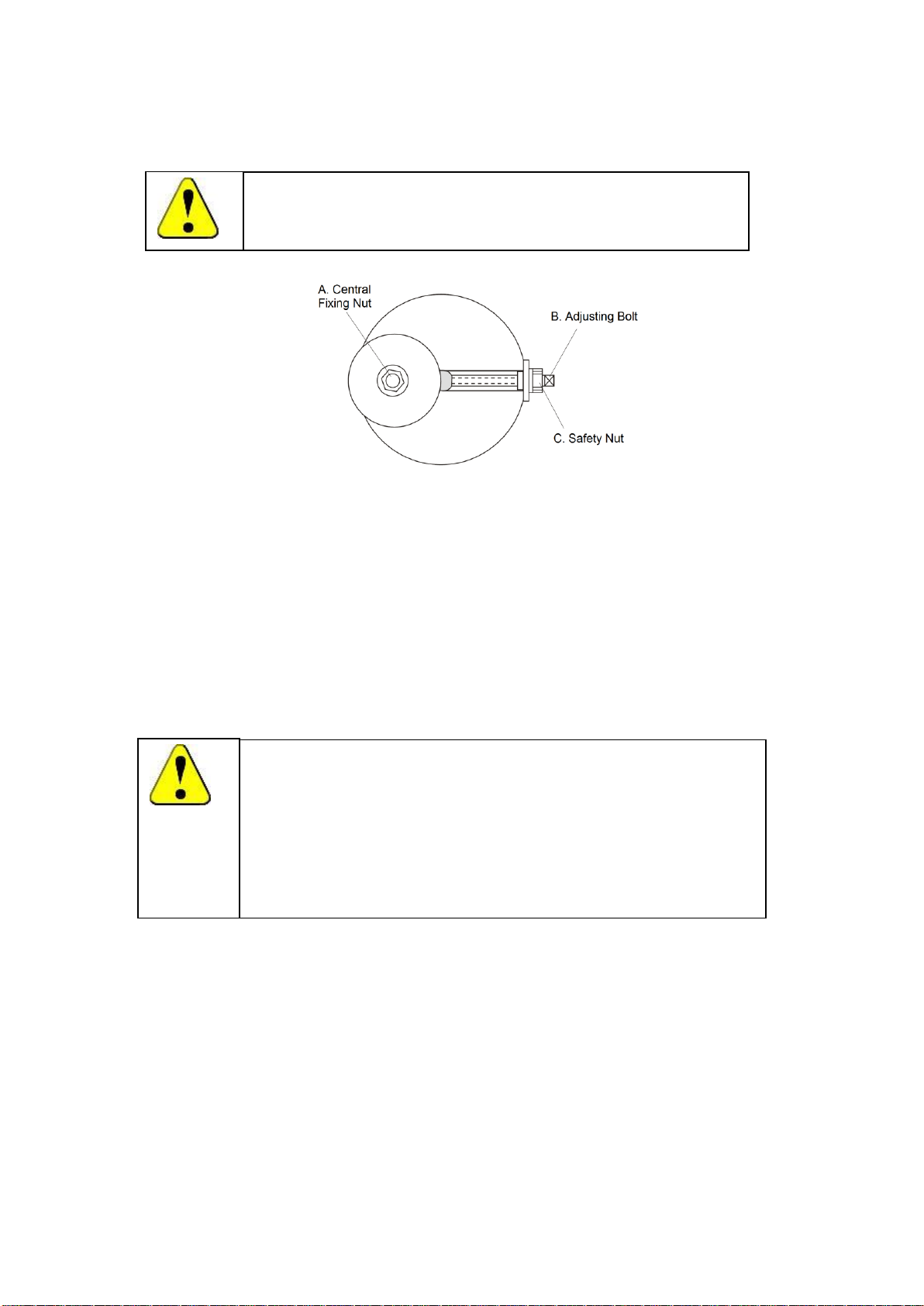
16. Shaking Diameter Adjustment (only for ZWF-111/211)
These models have an adjustable shaking stroke of Ø0-50mm. To adjust it, please follow the
instructions below,
16.1 Cut off the main power, remove the shaking tray. Manually turn the shaking mechanism until
the position like the picture above.
16.2 Tools needed: 17*19 spanner, 8*10 spanner, allen key (Included in accessory pack)
16.3 Turn off the unit, open the glass door, and pull platform tray out, until seeing the center of the
shaking mechanism (as illustrated)
16.4 Turn the main shaking mechanism until you see adjusting bolt (B) and safety nut (C) through
the opening.
16.5 Use the Allen key to loosen the (A) central fixing nut.
16.6 Use the 8*10 spanner to hold the (B) adjusting bolt as still, in the meantime, loosen the (C)
safety nut with 17*19 spanner
16.7 Use the 8*10 spanner to rotate the (B) adjusting bolt clockwise to increase the diameter, but
anti-clockwise to decrease.
16.8 When adjustment is done, tighten the (B) adjusting bolt and (A) central fixing nut.
17
Page 21
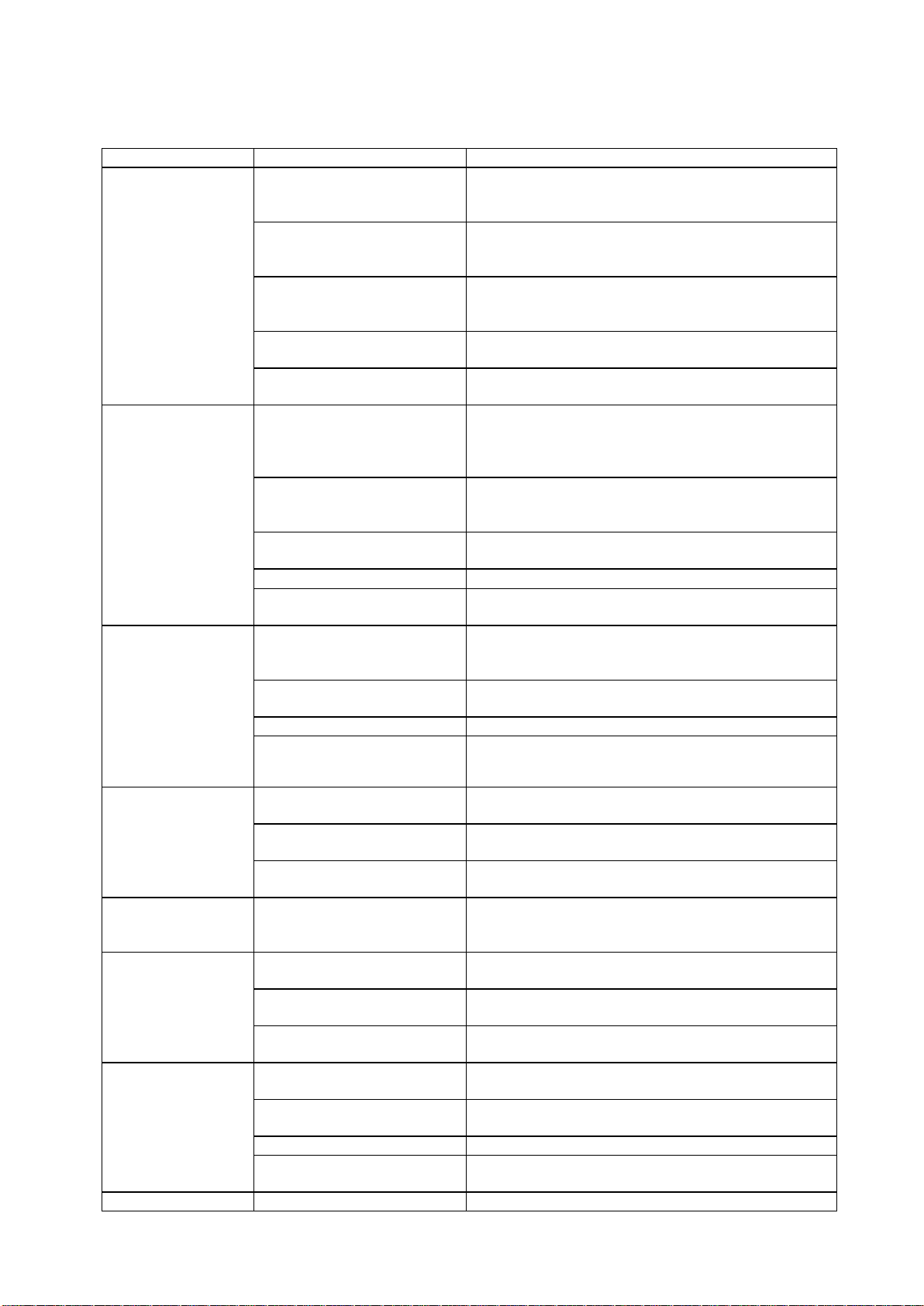
Error Indicator
Possible cause
Corrections
Power on ,
No display
Power supply is not
connected
Check the power supply system to see if there is
voltage on the line
Plug has no access to
socket
Plug in firmly
The power switch has not
been turned on.
Turn on the power switch on the right
side of the unit
The fuse is broken
Replace fuse with new one of same specification
Circuit occurs mall function
of power box
Notify distributor for repair service
Actual temperature
is higher than the
set point, high
temperature alarm
is activated
Unit has not yet reached the
required (constant)
temperature.
Wait a moment and observe
Temperature setting is at
the blind area of
temperature control
Open the ventilation hole
Improper setting of
refrigeration parameter
Set the refrigeration parameter to be “0.5”and close
the ventilation opening.
The ventilation fan is broken
Notify the distributor to replace the fan
Malfunction occurs with
refrigeration system
Notify the distributor to repair the refrigeration
system
Actual temperature
is lower than the
set point.
low temperature
alarm is activated
Unit has not yet reached the
required ( constant)
temperature
Wait a moment and observe
The circulation of cold air is
excessive
Close(a part of) the ventilation opening
The ventilation fan is broken
Notify the distributor to replace the fan
The heater does not work
Notify the distributor to repair the heater
Actual temperature
is fluctuating and
will not be stable
Improper setting of
refrigeration parameter
Refer to Users Guide and reset the refrigeration
parameter
The door (lid) is not closed
firmly
Close the door (lid) firmly
Malfunction occurs with the
control circuit
Notify distributor for repair service
Temperature is
constant out of
control
Malfunction occurs with the
control circuit
Notify distributor for repair service
The oscillation of
platform is unstable
The platform is in imbalance
due to a spoiled object
Remove the object , clear and clean the chamber
The equipment is not placed
horizontally
Adjust the left-back foot leveler install the
equipment in a proper way.
Malfunction occurs with
control circuit
Notify distributor for repair /service
The shaking
platform does not
work
The door switch has not yet
made contact
Check the door to see if it is closed firmly
The platform is blocked with
an object at the bottom
Remove the platform and clear the object and clean
the inside
The belt is broken
Notify the distributor to replace the belt
Malfunction occurs with
control circuit
Notify distributor for repair service
The oscillation of
Malfunction occurs with
Notify distributor for repair service
17. Trouble Shootings
18
Page 22

platform is out of
control
control circuit
The platform keeps
shaking after the
door is opened
The door switch has short
circuit ,could be caused by
humidity
Use a blower drier to dry the chamber
Press the Start/Stop button before opening the door
As the door is
closed ,the platform
starts shaking but
the speed runs high
suddenly
Improper operating method
Refer to Users Guide and press the Start/Stop
button to operate again
Screen has no
response when
button on the
control keyboard is
pressed
Equipment is disturbed by
high frequency.
Press the Change/Control button and try other
operation mode.
Restart the equipment-if it does not work:
Notify the distributor.
The equipment
causes a strange
loud noise
The equipment is not
placed horizontally
Adjust the left back foot to make the equipment
stable
The fixed screw of clamp is
loose
Remove the platform and tighten the screw
The platform is loose
Remove the platform an tighten the screws on the
four corners
There is strange object, like
a piece of a bottle, under the
platform
Remove the platform ,clear the object and clean the
inside
Mechanical malfunction
occurs
Notify the distributor for repair service
The accumulation
of frost is fast after
refrigeration is
started, resulting in
the rise of
temperature
The refrigerating time is too
long and the evaporating
chamber is too humid
Refer to Users Guide and conduct a drying
maintenance on the evaporation chamber
19
Page 23
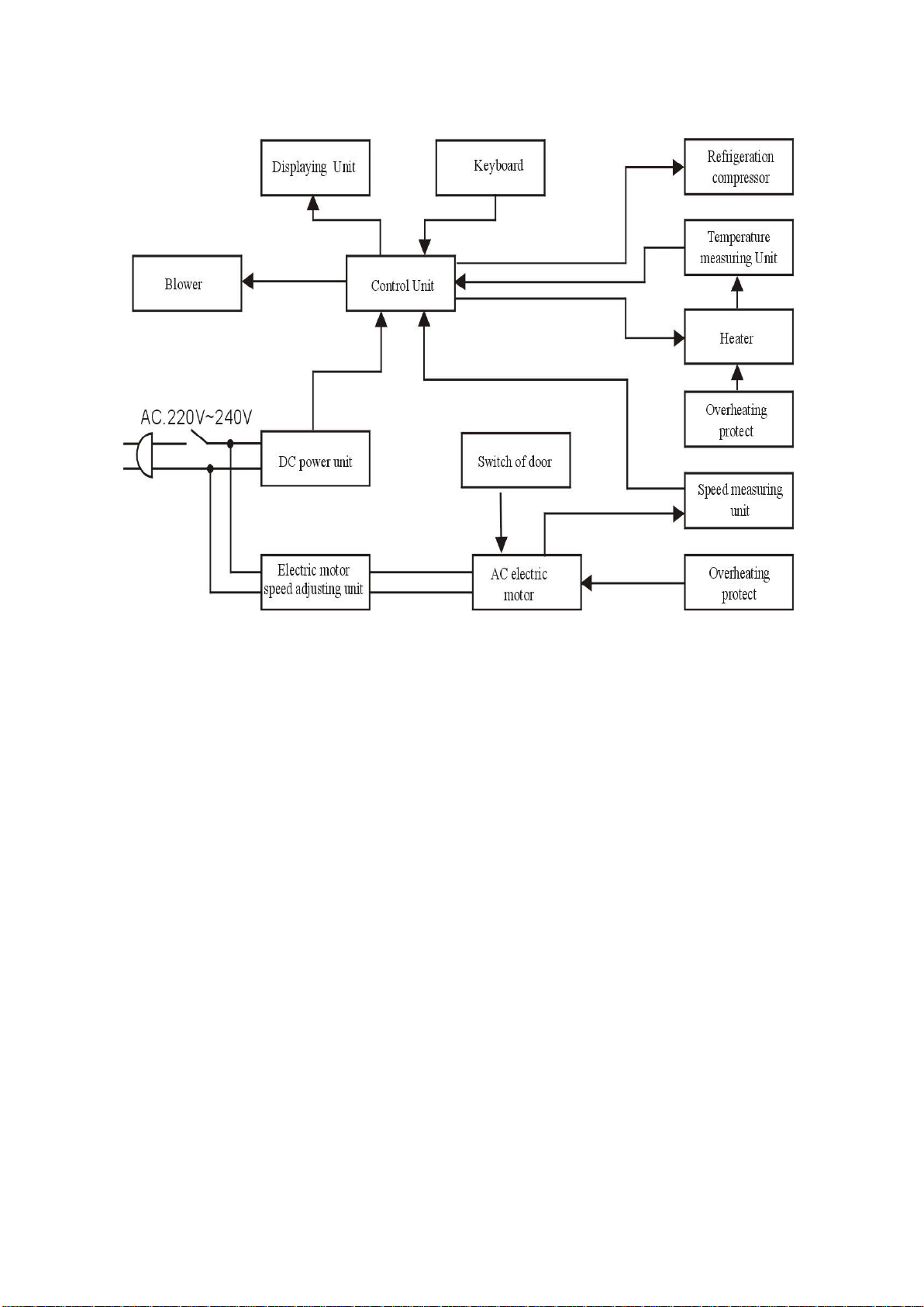
18. Electronic Control System
20
Page 24

19. After-Sale Service.
2. 2. After-sale service
Since the date of your purchase of this product, after-sale service of LABWIT will always be with you.
This product has a one year warranty that starts at the moment of delivery. If any malfunction caused
by defective in material or workmanship occurred during the warranty period, LABWIT will provide the
parts free of charge. Your distributor will provide professional workmanship and will repair the unit
without any charge. When this one year warranty is expired, we will continue to provide you with high
quality -life time services.
Please fully fill in the Return Card and send it back to the service department of LABWIT. In this way we
can keep you updated about technical improvements that might benefit the future performance of your
equipment.
For repair service, please contact your local dealer or log-in on our website
After-sale service
21
 Loading...