


YMF744/754 PCI SOUND CARD
Hardware Configuration
USER MANUAL
July 1999

FCC Compliance Statement
This equipment has been tested and found to comply with the limits for a Class B digital device, pursuant to Part
15 of the FCC Rules.
These limits are designed to provide reasonable protection against harmful interference in residential installation.
This equipment generates, uses, and can radiate radio frequency energy and, if not installed and used in
accordance with the instructions, may cause harmful interference to radio communications. However, there is no
guarantee that interference will not occur in a particular installation. If this equipment does cause interference to
radio or television reception, which can be determined by turning the equipment off and on, the user is encouraged
to try to correct the interference by one or more of the following measures:
• Reorient or relocate the receiving antenna.
• Increase the separation between the equipment and receiver.
• Connect the equipment into an outlet on a circuit different from that to which the receiver is connected.
• Consult the dealer or an experienced radio/TV technician for help.
Notice
This device complies with Part 15 of the FCC rules.
Operation is subject to the following two conditions:
(1) this device may not cause harmful interference, and
(2) this device must accept any interference received, including interference that may cause undesired
operation.
Shielded cables and I/O cords must be used for this equipment to comply with the relevant FCC regulations.
This digital apparatus does not exceed the Class B limits for radio noise emissions from digital apparatus set out in
the radio interference regulation of the Canadian Department of Communication

YMF744 PCI Sound Card Hardware Configuration
TABLE OF CONTENTS
1.1. DESCRIPTIONDESCRIPTION ..............................................................................................22
1.1 FEATURES ............................................................2
22 CCARD ARD FFIGURE FOR IGURE FOR “YMF744/754 N6YMF744/754 N6XX” ...............................................................33
2.1 CONNECTORS FOR “YMF744/754 N6X”............................................................................... 4
2.1.1 External Connectors:.....................................................................................................................4
2.1.2 Internal Connectors:......................................................................................................................4
2.2 AUDIO CONNECTORS PIN ASSIGNMENT:.........................................5
33 CCARD ARD FFIGURE FOR IGURE FOR “YMF744/754 R1YMF744/754 R1XX” ...............................................................66
3.1 CONNECTORS FOR “YMF744/754 R1X”............................................................................... 7
3.1.1 External Connectors:.....................................................................................................................7
3.1.2 Internal Connectors:......................................................................................................................7
3.2 AUDIO CONNECTORS PIN ASSIGNMENT:.........................................8
44 CCARD ARD FFIGURE FOR IGURE FOR “YMF744/754 R9YMF744/754 R9XX” ...............................................................99
4.1 CONNECTORS FOR “YMF744/754 R9X”............................................................................. 10
4.1.1 External Connectors:...................................................................................................................10
4.1.2 Internal Connectors:....................................................................................................................10
4.2 AUDIO CONNECTORS PIN ASSIGNMENT:........................................11
Page - 1

YMF744 PCI Sound Card Hardware Configuration
1. DESCRIPTION
Congratulations! You have just acquired a sound card based on the most
advanced 3D PCI audio accelerator available today. YMF744/754 PCI sound
card is a high performance PCI audio accelerator which combines the most
compelling 3D, quadraphonic and music synthesis technologies available with
full featured digital outputs. Full H/W acceleration of DirectSound®, 3D
audio, music synthesis, and gameport function guarantees exceptional system
performance.
1.1 Features
• PCI 2.2 compliant
• PCI Bus Power Management rev. 1.0 compliant
• PCI Bus master for PCI Audio
⇒ True Full Duplex Playback and Capture with different Sampling Rate
⇒ Maximum 64-voice XG capital Wavetable Synthesizer including GM compatibility
⇒ Direct Sound Hardware Acceleration
⇒ Direct Music Hardware Acceleration
⇒ Downloadable Sound (DLS) level-1
• Legacy Audio compatibility
⇒ FM Synthesizer
⇒ Hardware SoundBlaster Pro compatibility
⇒ MPU-401 UART mode MIDI interface
⇒ Joystick
• Supports PC/PCI and distributed DMA for Legacy DMAC (8237) emulation
• Supports Serialized IRQ.
• Optionally support Consumer IEC958 Output(SPDIF OUT)
• Optionally support Consumer IEC958 Input (SPDIF IN)
• Single Crystal operation (24.576 MHz)
• Compliant with AC’97 Requirements
⇒ 4 Stereo Inputs: LINE, CD, VIDEO, AUX
⇒ TAD connector for mono In and Output for modem Audio
⇒ 1 MIC Input
⇒ Stereo LINE Output/ Speaker Output
• 20 dB MIC Amplifier
• Analog Characteristics
⇒ A/D S/N: 85 dB
⇒ D/A S/N: 90 dB
• Low Power Consumption
Page - 2

YMF744 PCI Sound Card Hardware Configuration
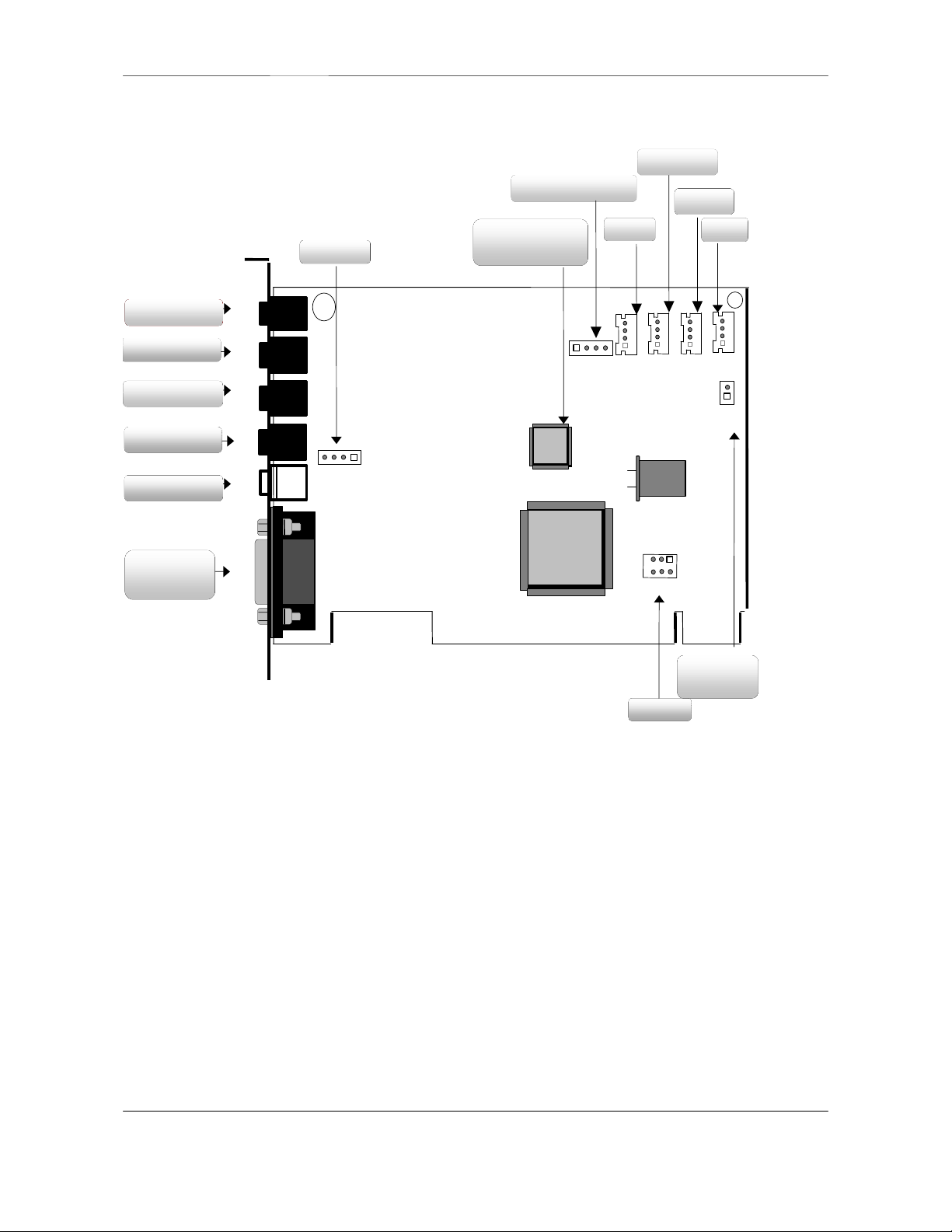
J1
Rear
Speaker
LINE IN
MIDI/
JOYSTICK
AC
97
PC/PCI
VIDEO
TAD
Power Amplifier
TEA 2025
MIC IN
J2
Front
Speaker
J3J4J5
J16
J13
CD-IN
J10
J14 J12
AUX In
CN3
AUDIO
Extension
CD-IN
J11
J19
PC-BEEP
Line-IN
Mic-IN
J6J7J8
Front-Out
J9
Rear Out
J20
AMP
2 Card Figure for “YMF744/754 N6x”
YMF744
or
YMF754
S/PDIF
lllllllllllllllllllllllllllllll
lllllll
Page - 3

YMF744 PCI Sound Card Hardware Configuration
2.1 Connectors for “YMF744/754 N6x”
2.1.1 External Connectors:
J1: ..................... ∅ 3.5mm Phone Jack for LINE IN
J2: ..................... ∅ 3.5mm Phone Jack for MIC IN
J3: ..................... ∅ 3.5mm Phone Jack for FRONT OUT
J4: ..................... ∅ 3.5mm Phone Jack for REAR OUT
J5: ..................... Connector for MIDI/JOYSTICK
2.1.2 Internal Connectors:
J6: ..................... Internal connector for LINE IN (optional)
J7: ..................... Internal connector for MIC IN (optional)
J8: ..................... Internal connector for FRONT OUT (optional)
J9: ..................... Internal connector for REAR OUT (optional)
J10:.................... Connector for CD AUDIO IN (Base Pin)
J11:.................... Connector for CD AUDIO IN (JST)
J12:.................... Connector for AUX IN.
J13:.................... Connector for TAD/VOICE MODEM.
J14:.................... Connector for VIDEO IN.
J16:.................... Connector for PC/PCI Legacy Audio SIDEBAND SIGNAL.
J19:.................... Connector for PC-BEEP (optional)
J20:.................... Connector for SPDIF IN/OUT (optional)
CN3:.................. Extension connector for 6-Channel AUDIO (optional)
Page - 4

YMF744 PCI Sound Card Hardware Configuration
J6/J7/J8/J9 (Optional)
RGG
L
G: GROUND
R: RIGHT CHANNEL SIGNAL
L G G R
G L G R
L G G R
L: LEFT CHANNEL SIGNAL
G: GROUND
R: RIGHT CHANNEL SIGNAL
L G G R
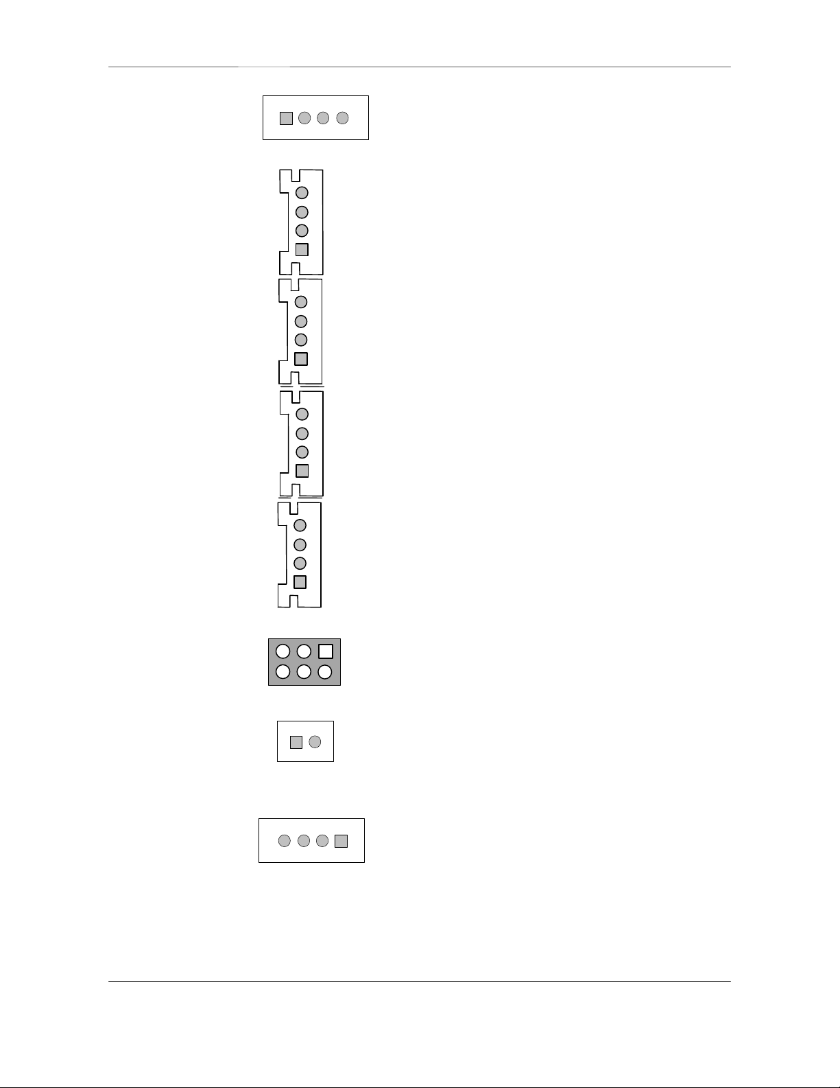
J10 (CD-IN)
J11 (CD-IN)
J12 (AUX-IN)
J13 (TAD/Voice Modem)
J14 (VIDEO-IN)
L: LEFT CHANNEL SIGNAL
1352461
2
3: N.C.
4: PCREQ#
5: GROUND
J16 (PC/PCI)
J19 (PC-BEEP)/optional
L: LEFT CHANNEL SIGNAL
G: GROUND
2,3: GROUND
2.2 Audio Connectors Pin Assignment:
R: RIGHT CHANNEL SIGNAL
L: LEFT CHANNEL SIGNAL
L: LEFT CHANNEL SIGNAL
G: GROUND
R: RIGHT CHANNEL SIGNAL
J20(SPDIF In/Out)
(Optional)
1 2 3 4
1: PHONE IN
2,3 : GROUND
4: MONO OUT
G: GROUND
R: RIGHT CHANNEL SIGNAL
1: PCGNT #
2: GROUND
6: SERIRQ#
1: PC SPEAKER OUT
2: +5V
4
3
2
1
1: S/PDIF INPUT
4: S/PDIF OUTPUT
Page - 5

YMF744 PCI Sound Card Hardware Configuration
J1
lllllll
‘97
PC/PCI
CD-IN
TAD
REAR OUT
J2
J3J4J6
CD-IN
(Option)
J5
SPDIF
3 Card Figure for “YMF744/754 R1x”
VIDEO-IN
AUX-IN
4 channel AC
’97 Codec
MIC IN
LINE IN /
J13
J12
J19
FRONT OUT
SPDIF IN
AC
J10
J14
J11
SPDIF OUT
MIDI/
JOYSTICK
J20
YMF744
OR
YMF754
J16
PC-BEEP
Page - 6

YMF744 PCI Sound Card Hardware Configuration
3.1 Connectors for “YMF744/754 R1x”
3.1.1 External Connectors:
J1: ..................... ∅ 3.5mm Phone Jack for MIC IN
J2: ..................... ∅ 3.5mm Phone Jack for LINE IN/REAR OUT(Switch by Software)
J3: ..................... ∅ 3.5mm Phone Jack for FRONT OUT
J4: ..................... Phone Jack for SPDIF IN(RCA or OPTICAL FIBER)
(Note: You can simultaneously use either J4 or J20 as SPDIF input at the same time)
J5: ..................... Phone Jack for SPDIF OUT(RCA or OPTICAL FIBER)
J6: ..................... Connector for MIDI/JOYSTICK
3.1.2 Internal Connectors:
J10:.................... Connector for CD AUDIO IN (Base Pin)
J11:.................... Connector for CD AUDIO IN (JST)
J12:.................... Connector for AUX IN.
J13:.................... Connector for TAD/VOICE MODEM.
J14:.................... Connector for VIDEO IN.
J16:.................... Connector for PC/PCI Legacy Audio SIDEBAND SIGNAL.
J19:.................... Connector for PC-BEEP (optional)
J20:.................... Connector for SPDIF In/Out (optional)
(Note: You can simultaneously use either J4 or J20 as SPDIF input at the same time)
Page - 7
YMF744 PCI Sound Card Hardware Configuration
G: GROUND
R: RIGHT CHANNEL SIGNAL
L G G R
G: GROUND
R: RIGHT CHANNEL SIGNAL
2,3 : GROUND
4:
MONO OUT
J10 (CD-IN)
J12 (AUX-IN)
J13 (TAD/Voice Modem)
J14 (VIDEO-IN)
L: LEFT CHANNEL SIGNAL
121
352
4
6
3: N.C.
4: PCREQ#
5: GROUND
J16 (PC/PCI)
J19 (PC-BEEP)
1: PC SPEAKER OUT
2: +5V
J11 (CD-IN)
RGL G RGG L 123 4 RGG
L
4 3 2 1
3.2 Audio Connectors Pin Assignment:
L: LEFT CHANNEL SIGNAL
L: LEFT CHANNEL SIGNAL
G: GROUND
R: RIGHT CHANNEL SIGNAL
L: LEFT CHANNEL SIGNAL
1: PHONE IN
J20 (S/PDIF-In/Out)
(Optional)
G: GROUND
R: RIGHT CHANNEL SIGNAL
1: PCGNT #
2: GROUND
6: SERIRQ#
1: S/PDIF INPUT
2,3: GROUND
4: S/PDIF OUTPUT
Page - 8
YMF744 PCI Sound Card Hardware Configuration
J1
lllllll
‘97
PC/PCI
CD-IN
TAD
LINE IN
J2
J3J4J6
CD-IN
(Option)
J5
SPDIF
4 Card Figure for “YMF744/754 R9x”
VIDEO-IN
AUX-IN
4 channel AC
’97 Codec
MIC IN
FRONT OUT
REAR OUT
SPDIF OUT
MIDI/
JOYSTICK
J20
AC
YMF744
OR
YMF754
J10
J11
J14
J16
J13
J12
J19
PC-BEEP
Page - 9

YMF744 PCI Sound Card Hardware Configuration
4.1 Connectors for “YMF744/754 R9x”
4.1.1 External Connectors:
J1: ..................... ∅ 3.5mm Phone Jack for MIC IN
J2: ..................... ∅ 3.5mm Phone Jack for LINE IN
J3: ..................... ∅ 3.5mm Phone Jack for FRONT OUT
J4: ..................... ∅ 3.5mm Phone Jack for REAR OUT
J5: ..................... Phone Jack for SPDIF OUT(RCA or OPTICAL FIBER)
J6: ..................... Connector for MIDI/JOYSTICK
4.1.2 Internal Connectors:
J10:.................... Connector for CD AUDIO IN (Base Pin)
J11:.................... Connector for CD AUDIO IN (JST)
J12:.................... Connector for AUX IN.
J13:.................... Connector for TAD/VOICE MODEM.
J14:.................... Connector for VIDEO IN.
J16:.................... Connector for PC/PCI Legacy Audio SIDEBAND SIGNAL.
J19:.................... Connector for PC-BEEP (optional)
J20:.................... Connector for SPDIF In/Out (optiona)
Page - 10

YMF744 PCI Sound Card Hardware Configuration
G: GROUND
R: RIGHT CHANNEL SIGNAL
L G G R
G: GROUND
R: RIGHT CHANNEL SIGNAL
2,3 : GROUND
4:
MONO OUT
J10 (CD-IN)
J12 (AUX-IN)
J13 (TAD/Voice Modem)
J14 (VIDEO-IN)
L: LEFT CHANNEL SIGNAL
121
352
4
6
3: N.C.
4: PCREQ#
5: GROUND
J16 (PC/PCI)
J19 (PC-BEEP)
1: PC SPEAKER OUT
2: +5V
J11 (CD-IN)
RGL G RGG L 123 4 RGG
L
4 3 2 1
4.2 Audio Connectors Pin Assignment:
L: LEFT CHANNEL SIGNAL
L: LEFT CHANNEL SIGNAL
G: GROUND
R: RIGHT CHANNEL SIGNAL
L: LEFT CHANNEL SIGNAL
1: PHONE IN
J20 (S/PDIF-In/Out)
(Optional)
G: GROUND
R: RIGHT CHANNEL SIGNAL
1: PCGNT #
2: GROUND
6: SERIRQ#
1: S/PDIF INPUT
2,3: GROUND
4: S/PDIF OUTPUT
Page - 11
 Loading...